1
ADEMCO VISTA-12A
ADEMCO VISTA-12E
Security Systems
User Guide
K10021-1 9/04 Rev. A
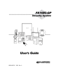
SYSTEM COMPATIBILITY NOTICE
Your Honeywell security system is designed for use with devices manufactured or
approved by Honeywell for use with your security system. Your Honeywell security
system is not designed for use with any device that may be attached to your security
system's keypad or other communicating bus if Honeywell has not approved such device
for use with your security system. Use of any such unauthorized device may cause damage
or compromise the performance of your security system and affect the validity of your
Honeywell limited warranty. When you purchase devices that have been manufactured or
approved by Honeywell, you acquire the assurance that these devices have been
thoroughly tested to ensure optimum performance when used with your Honeywell
security system.
IMPORTANT: If the keypad beeps rapidly upon entering the premises, it
indicates that an alarm has occurred during your absence and an intruder
may still be on the premises. LEAVE IMMEDIATELY and CONTACT
THE POLICE from a nearby safe location.
–2–
Table of Contents
Burglary System Features ........................................................................................................ 4
Basic Features ........................................................................................................................... 4
Exit/Entry Delays ...................................................................................................................... 5
Before Arming (Ready [∗] Key) ................................................................................................. 6
Bypassing Zones ........................................................................................................................ 6
Basic Arming Modes.................................................................................................................. 7
Disarming and Silencing Alarms.............................................................................................. 8
Using the Keyswitch.................................................................................................................. 9
Emergency Alarms (Panic Keys) .............................................................................................. 9
Non-Alarm Functions ............................................................................................................... 10
Chime Mode ............................................................................................................................. 10
Using the Voice Message Center ............................................................................................ 10
Using Macro Keys.................................................................................................................... 11
System Devices ........................................................................................................................ 11
Follow-Me Feature (audio beeps) ........................................................................................... 11
Advanced System Functions .................................................................................................. 13
Accessing Other Partitions ..................................................................................................... 13
Defining Macro Keys ............................................................................................................... 14
Schedules.................................................................................................................................. 14
Time and Date Functions........................................................................................................ 16
Event Log ................................................................................................................................. 17
Security Codes and Authority Levels ..................................................................................... 18
How to Assign User Codes and Attributes............................................................................. 19
Testing and Maintaining the System ................................................................................... 20
Testing the System (to be conducted weekly) ........................................................................ 20
Maintaining the System.......................................................................................................... 20
Trouble Conditions ................................................................................................................... 22
Fire Alarm System (If Installed)............................................................................................ 24
Quick Guide to Basic System Functions ............................................................................. 26
Charts of Your System’s Features ......................................................................................... 27
–3–
Burglary System Features
Basic Features
Partitions
Zones
Keypads
Voice Keypads
Security Codes
Arm/Disarm
–4–
• Partitions provide two independent areas of protection, with each partition containing a
group of zones that can be armed and disarmed without affecting other zones or users.
• Partitioned systems can include a common area, which is an area shared by users of two
other partitions (such as a lobby in a building).
• Some users may be given the authority to view status and arm/disarm other partitions.
• See Accessing Other Partitions section for details.
• Each partition consists of specific protection points known as zones.
• When a zone is faulted, its zone number is displayed on the keypad for easy identification.
• The system is controlled from the keypad, and the keypad displays system status.
• Each keypad is assigned a default partition for display purposes, and will show only that
partition's information.
• When entering codes and commands, sequential key depressions must be made within 4-5
seconds of one another. If 4-5 seconds elapse without a key depression, the entry will be
aborted and must be repeated from its beginning.
• If you make a mistake while entering a security code, stop, press the [∗] key, and then start
over. If you stop in the middle while entering a code, and then immediately start the entry
over, an erroneous code might be entered.
Keypad Lockout: The system may have been programmed to lockout the keypads for 15
minutes if more than 30 keystrokes (within a 15 minute period) are made without a valid
user code plus command being entered. The message “Code Sabotage” is displayed during
the lockout period.
• Voice Keypads (if installed), are functionally the same as other keypads.
• Voice announcements of system status (see Before Arming section)
• Voice chime, which can alert you to the opening of doors and windows while the system is
disarmed (see Voice Chime in Chime mode section)
• Message center, which lets you record and playback messages (see Using the Voice Message
Center in the System Overview section).
• Your installer assigned you a security code at the time of installation. This code is required
to perform most system functions.
• Each security code can have a different authority level, which defines the functions each user
can perform. Refer to the Security Code section for details on adding and changing security
codes.
• You can arm your system in several different modes, depending on whether you are staying
in or leaving the premises.
• To arm the system, simply enter your security code followed by the desired arming mode
key.
• To disarm the system, enter your security code followed by [1] OFF.
• Refer to the Arming/Disarming sections for specific arming commands.
Exit/Entry Delays
Exit Delay
Part. 1: _____ sec
Part. 2: _____ sec
Common: Same as
Part. 1
• When you arm the system, the system gives you a programmed amount of time to leave
through the designated exit door and/or certain other zones (if programmed) without
setting off an alarm.
• A slow beeping, if programmed, will sound during the exit delay period until the last 10
seconds, which then changes to fast beeping.
• If programmed, the keypad displays a countdown of the number of seconds of exit delay
remaining.
• When exit delay expires, all zones become protected and cause an alarm if opened.
• Your system may have been programmed such that exit delay remains in effect until a final
zone (e.g.,, exit door) has been closed for five seconds. Ask your installer.
Exit Delay
Restart
• Press the [∗
∗] key if armed in STAY mode to restart the exit delay timer.
• This gives you time to open the entry/exit door to let someone in after arming STAY. The
system (If programmed), automatically rearms when exit delay expires, which avoids
having to disarm the system and then rearm it again.
• When the system is armed AWAY, reopening and closing the entry/exit door before exit
delay time expires (e.g., reentering to get a forgotten item) will restart the exit delay time.
Entry Delay
• Gives you time to disarm the system when you re-enter through the designated entrance
door. You must disarm the system before the entry delay period ends, or an alarm will
occur.
• See your installer for your delay times.
Partition 1
Delay 1: _______ seconds
Delay 2: _______ seconds
Exit Alarms
Partition 2
Delay 1: _______ seconds
Delay 2: _______ seconds
Common Partition
Delay 1: Same as Partition 1
Delay 2: Same as Partition 1
• If an entry/exit door or interior zone is faulted when the exit delay ends (e.g., exit door left
open), the system sounds an alarm and starts the entry delay timer.
• Disarming the system before entry delay ends stops the alarm sound.
• The message "CANCELED ALARM" or "CA" is displayed on the keypad, along with a zone
number indicating the faulted zone.
• No message is sent to the Central Monitoring Station.
• If you do not disarm the system before the entry delay ends, and an entry/exit door or
interior zone is still open, the alarm sound continues and an "exit alarm" message is sent to
the Central Monitoring Station. The message ""EXIT ALARM" or "EA" and the faulted zone
number is displayed on the keypad.
• To stop the alarm, the system must be disarmed (your code plus OFF), to clear the display,
enter your code plus OFF a second time.
• An “exit alarm” also results if an entry/exit door or interior zone is faulted within two
minutes after the end of the exit delay.
To clear an exit alarm:
• Make the open zone intact, then
• Enter your code plus [1] OFF to clear the display.
Your system may have been programmed for this feature to minimize false alarms sent to the
Central Monitoring Station. Ask your installer if "Exit Alarm" is active in your system. If so,
check this box: [ ]
–5–
Before Arming (Ready [∗
∗] Key)
Not Ready
Voice Status:
Ready
• Before arming the system, you should close or bypass all protected doors, windows and
(using [∗
∗] key), other protection zones.
• Press [∗
∗] to display open zones (do not enter code first).
• To bypass zones, see the Bypassing Zones section below.
• Some systems, if programmed, may allow arming even if selected zones in the exit route are
faulted. Depending on the programming, these zones, if left faulted when exit delay expires,
will either be automatically bypassed or cause an alarm. See your installer.
• Voice Keypads (if installed), can announce system status and faulted zones (up to 3 zone
descriptors) if Voice Status is on.
• To turn Voice Status on/off: [#] + [0] [2] [4]
(Also turns on Voice Chime mode; see Chime mode section)
• To announce System Status: Press [∗
∗] STATUS key once.
• To announce faulted zones: Press the [∗
∗] STATUS key a second time within 5
seconds of the first press
• All zones are closed or bypassed and you can now arm the system.
• Some systems, if programmed, may allow arming even if selected zones in the exit route are
faulted. Depending on the programming, these zones, if left faulted when exit delay expires,
will either be automatically bypassed or will cause an alarm. See your installer for your
system’s programming.
Bypassing Zones
Bypass Notes
To Bypass
Zones
Quick Bypass
Active? ____
–6–
• You can bypass zones before arming the system or while the system is already armed.
• Your system may have a limit on the total number (1-7) of zones you may bypass (check with
your installer).
• Bypassed zones are unprotected and will not cause an alarm if violated.
• The system will not allow fire zones to be bypassed.
• Zones are automatically unbypassed when the system is disarmed.
• Vent Zones: Your system may have certain windows set as “vent” zones, which are
automatically bypassed if left open when arming the system (you do not need to manually
bypass them). However, if a vent zone window is closed after arming, it becomes protected
and will cause an alarm if opened again while the system is armed.
• Security code + [6] BYPASS + zone numbers
• Use 2-digit zone number(s) for the zone(s) to be bypassed.
• Single digit zone numbers must be preceded by a zero (e.g., 05, 06).
• When finished, the keypad will momentarily display a "Bypass" message for each bypassed
zone number.
• Wait for all bypassed zones to be displayed, then arm the system as usual.
• When armed, “ZONE BYPASSED” is displayed with the arm message.
• To display bypassed zones prior to arming, enter your security code and press the [6]
BYPASS key.
•Security Code+ [6] BYPASS + [#]
• Wait for all bypassed zones to be displayed, then arm the system.
• In a few moments, all open zones will be displayed and automatically bypassed. Make sure
that only those zones that you wish to leave unprotected are bypassed, and that there are
no other zones unintentionally left open.
• Allows you to easily bypass all open (faulted) zones without having to enter zone numbers
individually. This feature is useful if, for example, you routinely leave certain windows open
when arming at night.
Basic Arming Modes
Stay
•
•
•
•
•
•
Night-Stay
(Internal)
•
•
•
•
•
•
Instant
•
•
•
•
•
•
Away
•
•
•
•
•
•
Maximum
Step Arming
Quick Arm
Function Key
Arming
•
•
•
•
•
•
•
•
•
•
•
Security code + [3] (STAY)
Causes: three beeps, armed STAY displayed, ARMED indicator lights
Arms perimeter sensors, but interior sensors are left disarmed.
Use when you want to arm the system with persons staying inside (or if you have pets that
are moving throughout the premises).
Alarm sounds if any protected window or non-entry/exit door is opened.
Persons entering later can enter through an entry/exit door, but they must disarm the
system within the entry delay period to avoid sounding an alarm.
Security code + [3] + [3]
Causes: three beeps, NIGHT-STAY displayed, ARMED indicator lights
Same as Stay mode, plus pre-selected interior sensors, while other interior sensors are left
disarmed.
Use Night-Stay (internal) mode to provide increased security while staying inside.
Persons entering later can use an entry/exit door but they must disarm the system and
must not violate any of the programmed interior zones to avoid sounding an alarm.
IMPORTANT: When Night-Stay mode is on, the selected interior zones are armed and
cause an alarm if anyone enters those areas (e.g., waking in the middle of the night). To
avoid sounding an alarm, you must disarm the system before any activity takes place in
those zones.
Security code + [7] (INSTANT)
Causes: three beeps, armed INSTANT displayed, ARMED indicator lights
Arms same as Stay mode but with entry delay off.
Use when staying inside and do not expect anyone to use an entry/exit door.
An alarm sounds immediately if any protected perimeter window or any door is opened,
including entry/exit doors.
IMPORTANT: Arming in this mode greatly increases the chance of false alarms. Use
extreme care in selecting this mode of arming.
Security code + [2] (AWAY)
Causes: beeping during exit delay, armed AWAY displayed, ARMED indicator lights
Arms entire system (interior and perimeter).
Use when nobody will be staying inside (including pets).
An alarm sounds if a protected window or any door is opened, or if any movement is
detected inside your premises.
When reentering through an entry/exit door, you must disarm the system within the entry
delay period to avoid sounding an alarm.
Security code + [4] (MAXIMUM)
Causes: same as Away mode; arms same as Away mode, but entry delay is off.
Use when arming/disarming is being done from the outside (e.g.,, RF keyfob)
Press designated key A, B, C, or D, if programmed, once, twice or three times depending
on the arming mode desired. Each key press increases the level of security.
First press: arm STAY; second press: arm Night-STAY; third press: arm AWAY
Press [#] + arming command key, if programmed.
This feature lets you press [#] in place of the security code when arming the system.
The security code must always be used to disarm the system.
Press and hold the assigned function key for 2 seconds, if programmed.
You do not need to enter your security code before pressing the arming key.
Arms in designated arming mode. See your installer for the designated functions.
–7–
Disarming and Silencing Alarms
•
•
•
To Silence a
•
Burglary Alarm •
•
To Silence a
•
Fire Alarm
•
•
Memory of
•
Alarm
•
Disarming
Security code + [1] OFF
The “READY” indicator lights if all zones are secure
The keypad emits a single tone to confirm that the system is disarmed.
Security code + [1] OFF
The “READY” indicator lights if all zones are secure
The keypad emits a single tone to confirm that the system is disarmed.
Simply press the OFF key
The “READY” indicator lights if all zones are secure
The keypad emits a single tone to confirm that the system is disarmed.
When an alarm condition occurs, the keypad displays the number(s) of the zone(s)
that caused the problem, and displays the type of alarm.
To Clear Alarm Display and/or “Alarm Canceled” display: Security code + [1] OFF
again
• Note the zone in alarm on the keypad display, and make that zone intact (close door,
window, etc.).
• The message remains displayed even after disarming the system, but can be cleared with
another “disarm” sequence.
IMPORTANT: If you return and the main burglary sounder is on, DO NOT ENTER, but CONTACT THE
POLICE from a nearby safe location.
If you return after an alarm has occurred and the main sounder has shut itself off, the keypad will beep rapidly
upon your entering, indicating that an alarm has occurred during your absence.
LEAVE AT ONCE, and CONTACT THE POLICE from a nearby safe location
–8–
Using the Keyswitch
GREEN
RED
Green Light:
Red Light:
• Your system may be equipped with a keyswitch for arming and disarming.
• To arm in AWAY mode: Turn the key to the right for 1/2 second and release.
Keypads beep twice and the red indicator lights or flashes.
• To arm in STAY mode: Turn the key to the right and hold for more than 1
second, then release. Keypads beep three times and the red indicator lights or
flashes.
• To disarm the system: Turn the key to the right and release. The red light turns
off.
• Lights when the system is disarmed and ready to be armed (no open zones).
• If the green light is off, the system is not ready (one or more zones are open).
• Lights or flashes when system is armed in AWAY or STAY mode. See your
installer for the meanings of the lit red light:
• Lit Steady = system armed AWAY or STAY and exit delay has expired
• Flashing = system armed STAY and exit delay timer active
• Rapid Flashing = an alarm has occurred (memory of alarm)
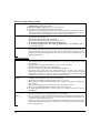
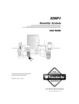
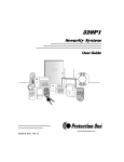
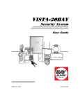
Emergency Alarms (Panic Keys)
Your system maybe programmed to use special keys to manually activate emergency (panic) functions.
Silent Alarm
• Sends silent alarm signal to monitoring station.
• Causes no audible alarm or change in display indicating that a silent alarm has been
initiated.
Audible Alarm
• Sends audible alarm signal to monitoring station.
• Causes a loud, steady alarm at keypad(s) and at any external sounders that may be
connected.
Personal Alarm
• Sends emergency alarm signal to monitoring station.
• Causes steady alarm sound at keypad(s), but not at external bells or sirens.
Fire Alarm
• Sends fire alarm signal to monitoring station.
• Causes temporal (pulsing) sound at external bells and sirens.
To use an
• Press and hold down for at least 2 seconds whichever lettered key on the keypad has
been programmed for the desired emergency function.
Emergency Key
OR
Briefly press both keys of the assigned key pair at the same time
• See your installer for the functions that have been programmed for your system.
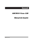
A
ZONE 95
ZONE 99
ARMED
READY
C
CPU
1
2
3
OFF
AWAY
STAY
MAXIMUM
TEST
BYPASS
4
7
INSTANT
ZONE 96
8
CODE
0
D
Lettered Panic Keys
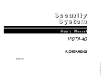
2
1
ZONE 95
CPU
9
AWAY
STAY
TEST
BYPASS
INSTANT
CODE
CHIME
4
7
CHIME
#
3
MAXIMUM
OFF
READY
6
READY
6164-010-V0
READY
5
ARMED
5
8
0
6
9
PRESS BOTH KEYS
OF DESIRED PAIR
AT THE SAME TIME
ZONE 96
#
ZONE 99
6164-011-V0
B
Panic Key Pairs
–9–
Non-Alarm Functions
Chime Mode
Chime mode alerts you to movement within the premises while the system is disarmed.
Chime Mode on • Security code + [9] (Chime message appears)
• Keypads sound three beeps whenever a protected door, window or other specified zone is
opened.
• Pressing the [∗] READY key will display the open protection points.
Chime Mode off • Security code + [9] again (Chime message disappears)
Voice Chime:
Voice Chime
on/off
• You can set the Voice Keypad(s) (if installed) to announce faulted (opened) entry/exit or
perimeter zones whenever normal Chime mode is on.
• [#] + [0] [2] [4] (normal Chime mode must be on first)
• When Voice Chime is on, faulted zones cause a voice status announcement, chime and
display.
• When off, the sounder still provides chime if normal Chime mode is on.
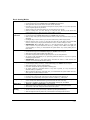
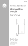
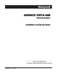
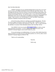
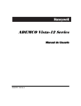
Using the Voice Message Center
The Voice Keypads feature a voice message center that lets you record and playback one message.
SPEAKER
LCD
DISPLAY
1
ARMED
LEDs
OFF
2
AWAY
RECORD
VOLUME
READY
4
MAX
5
TEST
MESSAGE
7
INSTANT
8
CODE
READY
0
MIC
STATUS
MICROPHONE
STATUS
KEY
VOICE
KEY
PLAY KEY
AND
UP VOLUME
VOLUME
KEY
RECORD
KEY
VOICE
3
STAY
PLAY
6
BYPASS
9
CHIME
#
FUNCTION
FUNCTION
KEY
Message Center Functions
Record a
• [#] FUNCTION + [0] VOICE + [1] RECORD (red MESSAGE LED lights)
Message
• Message remains in memory until a new message is recorded.
End Recording • [1] RECORD (red MESSAGE LED flashes, indicating message waiting)
Play a Message • [#] FUNCTION + [0] VOICE + [3] PLAY
• The recorded message plays and the red MESSAGE LED turns off.
Adjust the
• [#] FUNCTION + [0] VOICE + [2] VOLUME keys,
Volume
• then press volume key [3] ↑ (up) or [6] ↓ (down)
• Adjusting message volume also adjusts status volume.
• Volume cannot be adjusted while playing.
– 10 –
DOWN
VOLUME
6160V-00-005-V0
Basic Information
• The message can be up to 2.5-minutes long
• The message remains in the keypad’s memory until
a new message is recorded.
• The volume control of the message is adjustable.
• Refer to the procedures below when using the
Message Center functions.
Using Macro Keys
See Defining Macro Keys section in the Advanced System Features section for details on defining macro keys.
Macro Keys
• The “A”, “B”, “C” or “D” key may have been pre-programmed as a “macro” key.
• Macros can be activated only by users authorized to perform the macro’s function.
Using a
• Press and hold the defined Macro key for at least 2 seconds.
Macro Key
The “Enter User Code” prompt appears and remains displayed for up to 10 seconds.
• Enter your 4-digit user code.
• The programmed macro sequence begins automatically after the user code is entered.
System Devices
Your system may be set up so that it can control certain lights or other electrically operated devices.
About System
• Some devices may be automatically turned on or off by the system.
Devices
• You may be able to override automatically controlled devices.
• Some devices can be manually turned on or off using the commands described below.
• See your installer for a list of devices that may be set up for your system.
To Activate
Devices
• Security Code+ [#] + [7] + nn (nn = 2-digit device number)
• Devices associated with that device number activate.
To Deactivate
Devices
• Security Code+ [#] + [8] + nn (nn = 2-digit device number)
• Devices associated with that device number deactivate.
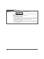
Follow-Me Feature (audio beeps)
About FollowMe/Beeps
• This feature lets users enter up to three phone numbers (system-wide) that the system will
call in the event of an alarm in any partition at the protected premises, thus alerting the
user to the alarm. The follow-me feature works as follows:
• When an alarm occurs, the system reports the alarm to the central station (and predetermined pagers, if programmed), then dials the first follow-me phone number.
• After dialing, the system waits a short time (about one ring plus any programmed pauses;
see “To enter a follow-me number” below for programming pauses) then begins sending
message tones (regardless of whether the call is answered).
• When answered, the user will hear the message tones (a series of eight tones or “beeps”)
followed by a pause of about four seconds, then the tones are repeated. The cycle of tones
and pauses continues for about one minute.
• The user should press the [∗
∗] key on the telephone to acknowledge hearing the tones,
then wait for the control to disconnect the line before hanging up. IMPORTANT: Press the
[∗] during a pause between tone cycles. Otherwise, the control may not “hear” the [∗] key if
pressed while the tones are being sent.
• If the user does not press the [∗] key, the control hangs up when the 1-minute tone cycle is
complete, then dials the second follow-me phone number. The control sends the tones as
described above.
• If the second number is not acknowledged by the user pressing the [∗] key, the control dials
the third number. If the [∗] key is not pressed during the third call, the control redials the
first number and the cycle repeats up to three times or until a user presses the [∗] key on
the telephone.
• If the follow-me number is for a pager, the message displayed on the pager is as follows: 104
P ZZZ
Where “P” is the partition number, “ZZZ” is the 3-digit zone number of the zone in alarm.
– 11 –
Follow-Me Feature (cont’d)
To enter a
follow-me
phone number
• User code + [#] + [6] [1]
• The first follow-me phone number (if one exists) is displayed:
FM Phone No.
18009216704--_
• To display follow-me phone number 2, press [2]. To display follow-me phone number 3,
press [3].
• To modify the displayed number, do the following:
1. Press [∗], which clears the number.
2. Enter the desired phone number.
To include a 2-second pause in the number, press [#] at the point in the entry the pause
is desired (it displays as “–“). Pauses entered at the end of the number will allow dialing
but will delay the message tones by the amount of pause programmed.
3. Press [∗] to save the new number.
The next follow-me phone number in sequential order (1-2-3-1 etc.) is displayed. Press
[∗] to program that number, or press [1], [2], or [3] to select the desired follow-me
number to be programmed.
– 12 –
Advanced System Functions
(System Master and Master users only)
Accessing Other Partitions
Partition
Basics
Common Area
GoTo
Command
Multi-Partition
Arming
• Each keypad is assigned to a partition by your installer and is used to perform functions in
that partition and display that partition’s system status.
• Certain users, if authorized, can “GoTo” another partition from their partition’s keypad to
perform functions in the other partitions or display another partition’s status. See GoTo
command below.
• Certain users, if authorized, can arm/disarm all partitions with a single command from
their home partition. See Multi-Partition Arming below.
• Your system may have been set up to use a common area, which is an area shared by users
of the other partitions, such as a foyer or lobby.
• If a common area is part of the system and one of the partitions is armed, faults occurring
in the common area will be displayed on its keypads and the disarmed partition’s keypads.
• The common area will be armed and will sound and report alarms only when both the
other partitions are armed; if either of the other partitions is disarmed, the common area
remains disarmed and ignores faults.
• Either partition can arm its system if the common area is faulted, but once armed, the
other partition will not be able to arm unless the faulted common area zone is bypassed or
the fault is removed.
• Either partition can clear and restore the common area after an alarm.
• Entry/exit time for the common area is the same as for partition 1.
• Security code + [∗
∗] + partition number (0,1,2, or 3), where:
0 = return to keypad’s original partition;
1 = partition 1;
2 = partition 2;
3 = common partition
• You can only “GoTo” those partitions that were assigned to you.
• Can only be performed using an Alpha keypad.
• The keypad remains in the new partition until directed to go to another partition, or until
it automatically returns to the original partition (after 2 minutes with no keypad activity).
• Security code + [0] + arming command (2, 3, 33, 4, 7, or 1), where:
2 = arms all partitions AWAY; 3 = arms all partitions STAY
33 = arms all partitions NIGHT-STAY (INTERNAL)
4 = arms all partitions MAXIMUM;
7 = arms all partitions INSTANT
1 = disarms all partitions
• You can use this feature only if you were given that authority.
• You must use an Alpha keypad.
• The system arms only if all partitions are “ready to arm” (unless the system is
programmed to allow arming with faults in certain zones); if any partition is “not ready,”
the system does not arm at all.
• You can use the GoTo command to bypass open zones before arming, if desired.
• If any partition is already armed when multi-partition arming is attempted, that partition
remains in its existing armed state.
– 13 –
Defining Macro Keys
Macro Key
Rules
To Define
Macro Keys
• Only the system master can define macros.
• A macro key is a convenience key that can activate up to 16 keystrokes.
• Typical functions include arming sequences, bypassing zones, or turning on/off electrically
operated devices.
• Two macros can be assigned in the system, but only to keys pre-programmed by the
installer.
• System Master Code + [#] + [6] [6]
• Follow the prompts.
• Enter the macro number (1-2; see installer for appropriate macro number) to be
programmed at the “Select Macro?” prompt.
NOTE: The two macros that can be defined can be made partition specific.
• If a macro has been previously defined, the keystrokes are shown on the bottom line of the
display, otherwise the display is blank.
To exit this mode (and keep the existing macro definition), press any key except the [∗]
key. The system returns to normal mode.
To define a macro for the selected key, press [∗] and continue with the next prompt.
Enter the first of the series of desired commands, (do not include your user code), then
press/hold the “D” key for at least two seconds to complete the first command. This key
terminates each command, and appears as an “F” in the display as shown:
MACRO PGM
60203F#701F2F
The keypad beeps to acknowledge your input and displays
the command you entered (followed by “F”).
• Enter the next command, followed by press/holding the “D” key for at least two seconds.
The keypad beeps and displays the keystrokes entered.
•. Repeat until all the desired commands have been entered (up to 16 characters including
the “F”s).
Check your keystrokes before continuing. If you made a mistake, you must start over.
• To exit, press/hold the “D” key for at least two seconds. The display returns to system
status and indicates system is ready.
Schedules
About Schedules
• The system provides up to 4 end-user schedules (programmable by master/installer
only), which can control various types of events.
• Each schedule causes a defined event to start and stop (when appropriate) at a
specified time.
• Schedules can be set to automatically repeat at various intervals and set for random
starting, if desired.
Creating Schedules
1. System Master Code + [#] + [6] [4]
2. Enter a 2-digit schedule number from 01-24.
Press [∗] to continue.
– 14 –
1 DISARMED
READY TO ARM
ENTER SCHED NO.
00=QUIT
00
Creating Schedules (cont’d)
3. Enter the desired 2-digit event number from the following list.
ENTER EVENT
00 = remove the scheduled event
01 = turn a programmed device on or off
02 = set a user access schedule for one or more users)
03 = send “child-not-home” report; see Child Not Home notes below
04 = automatically arm the system in STAY mode at a specified time (cannot be used if a common area
exists)
05 = automatically arm the system in AWAY mode at a specified time (cannot be used if a common area
exists)
06 = automatically disarm the system at a specified time
07 = Display the word “REMINDER” at a specified time
08 = Disarm Time Window (system can be disarmed only during this time period; Exception: if a burglary
alarm occurs, the system can be disarmed outside the scheduled time window)
Press [∗] to continue.
4. For event number “01,” enter the 2-digit output number (01-04, 17-18)
associated with this schedule. Otherwise, this prompt is skipped.
Press [∗] to continue to the “Start” prompt below.
5.
6.
7.
For event number “02,” enter the 1-digit access group number (1-8).
Otherwise, this prompt is skipped.
Press [∗] to continue to the “Start” prompt below.
For event numbers “03-08,” enter the partition number to be armed or
disarmed. Otherwise, this prompt is skipped.
0 = arm all; 1 = partition 1; 2 = partition 2; 3 = common partition
Press [∗] to continue to the “Start” prompt.
Enter the event’s start time and days of week: Hour = 00-23; minute = 0059
Days = Position the cursor under the desired days using the [∗] key to
move forward, then press “1” to select the day(s).
DEVICE NUMBER
XX
GROUP NUMBER
X
PARTITION
X
START
SMTWTFS
HH:MMAM
1000000
Press [∗] to continue.
8.
For events 04 or 05, enter the desired amount of time, 01-15 minutes, the
system should warn of impending arming. The system beeps once every 30
seconds to alert users that arming will soon occur. Otherwise, prompt is
skipped.
WARNING DELAY
TIME
00
Press [∗] to continue.
9.
Enter the event’s stop time and days of week. Refer to step 7 for available
entries.
Press [∗] to continue.
10. Enter the desired repeat option.
0 = no repeat; 1 = repeat schedule weekly
2 = repeat schedule biweekly (every other week)
3 = repeat schedule every third week; 4 = repeat schedule every fourth
week
e.g., To make a schedule that happens everyday you would select all days
with a repeat count of 1.
NOTE: Schedules run sequentially from Sunday to Saturday and reset on
Sunday at midnight. If repeat count is 0, only those events scheduled from
the day the schedule is set to Sunday will occur. Events scheduled after
Sunday will be ignored.
STOP
SMTWTFS
HH:MMAM
1000000
REPEAT
0-4
OPTION
X
– 15 –
Creating Schedules (cont’d)
11. Select the randomize option, if desired: 0 = no; 1 = yes
RANDOMIZE
If selected, the schedule times will vary within 60 minutes of the “hour”
0=NO 1=YES
X
time. For example, if a schedule is set to start at 6:15, it will do so the first
time 6:15 arrives, but on subsequent days it will start anytime between
6:00 and 6:59
This feature is typically used for lighting control to make an unoccupied
facility appear occupied during extended absences.
Press [∗] to return to the ENTER SCHED No. prompt.
Child-Not-Home
• You can program a schedule that causes a pager report to be sent to Pager 1 phone
number if the system is not DISARMED by the scheduled time (see event “03”). The
Paging
message sent is: 7 7 7 – 7 7 7 7 .
For example, a working parent might want a message to be sent to a pager if their
child did not arrive home from school and disarm the system by a certain time.
NOTE: Your installer must program the control for pager reporting before you can use
the child-not-home scheduling option (installer must program pager number
and report options).
Time and Date Functions
Viewing the Time
and Date
To Set the Time and
Date
– 16 –
•
•
•
•
•
Master Code+[#] + [6] [3], or if programmed, press the designated function key.
The system lets you view its time and date setting.
The display remains on for about 30 seconds.
Master Code+[#] + [6] [3], then press [∗] while the time/date is displayed.
A cursor appears under the first digit of the hour.
NOTE: To move cursor ahead, press [∗]. To go back, press [#].
• Enter the 2-digit hour setting; enter the 2-digit minute setting.
• Enter the last two digits of the current year.
• Enter the 2-digit month setting (01-12); enter the 2-digit day setting (01-31).
• Press [∗] to accept the settings and continue.
The Clock Adjustment prompt is displayed. This prompt lets you add or subtract up
to 59 seconds per day, if needed, to keep the real-time clock accurate.
• Press [0] to add seconds per day, or press [1] to subtract seconds per day.
• Enter the desired number of seconds per day (01-59) to add or subtract.
• Press [∗] to accept the settings and exit. This mode automatically exits after 10
seconds.
Event Log
The system records up to 254 events in a history log, which can be viewed by the master user using an Alpha
Display keypad.
To view the
• Master Code+ [#] + [6] [0]
Event Log
• The system displays the most recent event as follows:
Pressing [∗] displays previous events (back in time).
001 E441 U001 P1
Pressing
[#] displays events forward in time.
13:38 21/06/02
Exit Event Log
Event number, type of event, identified by its corresponding code, displayed in chronological
order, from most recent to oldest.
Zone or user number (depending on type of event), partition in which event occurred, time
and date of the event’s occurrence.
• When the log is full, the oldest event is replaced by the logging of any new event.
• Refer to the Event Log Codes Table below for the meanings of the various codes.
• Press any key other than [∗] or [#]
Event Log Codes Table
Code
110
121
122
123
131
132
134
135
143
144
145
146
150
162
301
302
305
309
321
333
341
344
351
353
354
373
374
380
381
382
383
384
393
Definition
Fire Alarm
Duress
Alarm, 24-hour Silent
Alarm, 24-hour Audible
Alarm, Perimeter
Alarm, Interior
Alarm, Entry/Exit
Alarm, Zone Type 5
Alarm, Expansion Module
Sensor Tamper Alarm
ECP Module Cover Tamper Alarm
Silent Burglary Alarm
Alarm, 24-Hour Auxiliary/Monitor zone
Gas Alarm
AC Power
Low System Battery/Battery Test Fail
System Reset (Log only)
Battery Fail
Siren Supervision Failure
Trouble, Expansion Mod. Supervision
Trouble, ECP Cover Tamper
RF Receiver Jam
Telecom Line Fault
Alternative Comm. Media Trouble
Failure to Communicate (log only)
Fire Loop Trouble
Exit Error Alarm
Trouble Zone Type 5
RF Supervision Trouble
Supervision Auxiliary Wired Zone
(sent after code 333 is sent)
RF Sensor Tamper and DoubleBalanced Zone Tamper
RF Sensor Low-battery
Clean Me (ESL smoke detectors only)
Code
401
403
406
407
408
409
412
441
442
461
570
601
602
606
607
623
625
626
627
628
641
750 789
801
802
803
804
999
Definition
Disarmed, Armed AWAY,
Armed MAXIMUM
Schedule Arm/Disarm AWAY
Cancel by User
Remote Arm/Disarm (Downloading)
Quick Arm AWAY
Keyswitch Arm/Disarm AWAY
Successful Download/Access
Disarmed/Armed STAY/INSTANT,
Quick-Arm STAY/INSTANT
Keyswitch Arm/Disarm STAY
Wrong Code Entry (keypad lockout
activated)
Bypass
Manually Triggered Dialer Test
Periodic Dialer Test
Audio Alarm Verification (AAV) to
Follow
Walk Test Entered/Exited
Event Log 80% Full
Real-Time Clock was Changed (log
only)
Time/Date Inaccurate
Program Mode Entry (log only)
Program Mode Exit (log only)
Senior Watch Trouble (up and about)
Reserved for Configurable Zone Type
report codes (check with central station
when using these codes)
Override Tamper Arming (log only)
Override Low Battery Arming (log only)
Override AC Loss Arming (log only)
Override Supervision Fail Arming (log
only)
Non-Alarm Zone Type (Zone Type 23)
Fault (log only)
– 17 –
Security Codes and Authority Levels
You can assign different security codes for use by other users.
Rules for
• Only the System and Partition Masters can assign user codes to users and change user
partitions.
Assigning
Codes
• User code programming involves these steps:
1. Choose a user number from the set of users assigned to the partition in which the user
will be operating, and assign a 4-digit security code.
2. Assign an authority level to that user.
3. Assign other attributes as necessary.
NOTE: The factory settings are designed to meet most normal user situations.
Therefore, the only step you usually need to do when adding users is to assign a user
number (from the partition’s pre-assigned user numbers) and a security code.
Authority Levels (define the system functions a particular user can/cannot perform)
Level
N/A
Title
System Master
Explanation
Reserved for user 02; Can perform all system functions and assign codes in
(default = 1234) all partitions; can change its own code as follows:
Master code + [8] + 02 + new master code + new master code again
0
Standard User:
Can only perform security functions in assigned partition. Cannot perform
other system functions
1
Arm Only:
Can only arm the system. Cannot disarm or do other functions.
2
Guest:
Can arm the system in assigned partitions, but cannot disarm the system
unless the system was armed with this code. This code is typically assigned
to someone (e.g., babysitter or cleaner) who has a need to arm/disarm the
system only at certain times. The user of this code should not use the “Quick
Arming” feature.
3
Duress Code:
Intended for use when you are forced to disarm or arm the system under
threat. When used, the system will act normally, but can silently notify the
Central Monitoring Station of your situation, if that service has been
provided.
4
Partition Master
Can do everything a standard user can do, and can assign user codes to users
in their partition and can change its own code as follows:
Partition master code + [8] + user number + new master code + new
master code again
– 18 –
How to Assign User Codes and Attributes
Refer to the User Setup chart at the back of this manual to keep a record of user programming.
NOTE: Partition Master codes apply only to those user numbers previously assigned (by the system master/
installer) to the partition master’s partition.
Add User Code:
(User 03 is preset to be
a partition 1 programmer,
but can be changed.)
System/Partition Master code + [8] + user no. + new user’s code
User 01 = installer
User 02 = master
User 03 = partition 1 master
The Keypad beeps once to confirm that new user was added.
Delete User Code:
System/Partition Master code + [8] + [user no.] + [#] + [0]
The user code and all attributes* programmed for this user number, including any
associated RF keys, are erased from the system. (*except assigned partition)
Authority Level:
System/Partition Master code + [8] + [user no.] + [#] + [1]+ auth. level
Authority Levels (see definitions above):
0 = standard user;
1 = arm only;
2 = guest;
3 = duress;
4 = partition master
Factory Assignments:
(Users 04-17 = 0
user 03 = 4)
Access Group:
Factory Assignments: none
User’s Partition:
Factory Assignments:
Part. 1 = users 03-17
RF User Number:
Factory Assignments: none
Arm/Disarm Report:
System/Partition Master Code + [8] + [user no.] + [#] + [2]+ group (1-8)
You can assign users to a group, then set an access schedule that defines the times this
group of users can operate the system. The system does not allow these users to control
the system outside the scheduled times.
System Master Code + [8] + [user no.] + [#] + [3] + [0] + partition(s) + [#]
This command assigns the partitions the user can access. If more
than one, enter partition numbers sequentially, then press [#] to end.
E.g., master code + [8] + [user no.] + [#] [3] + [0] + [1] [2] + [#] gives
the user access to partitions 1 and 2.
Partition Entries:
1 = partition 1; 2 = partition 2; 3 = common partition
Master/Part. Prog. Code + [8] + [user no.] + [#] + [4]+ zone no.
Use this command to assign a wireless button device (keyfob) to this user (keyfob
must be enrolled in system first; see installer).
Zone number: Enter the zone number assigned to the desired function button on the
keyfob that will be used by this user. Each button was assigned a unique zone
number. See your installer for appropriate zone numbers.
Master/Part. Prog. Code + [8] + [user no.] + [#] + [6] + 0 or 1
You can program a user so that a message is sent to the monitoring station whenever
this code is used to arm or disarm the system. 1 = send arm/disarm report; 0 = no
arm/disarm reporting for this user
– 19 –
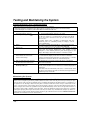
Testing and Maintaining the System
Testing the System (to be conducted weekly)
Test mode allows each protection point to be checked for proper operation.
• The keypad sounds a single beep every 40 seconds as a reminder that the system is in the Test mode.
• Alarm messages are not sent to your Central Station while Test mode is on.
1 Disarm the system and close all
The READY indicator light should come on if all zones are intact
protected windows, doors, etc.
(i.e., all protected windows, doors, etc. are closed.
Starts Test mode.
2. Security Code+ [5] then [0]
(walk)
The Dial test (option “1”) is intended for the installer and should
not be used unless directed to do so by your Security System
Representative
If, during these tests, a problem is experienced with any
protection point (no confirming sounds, no display), call for
service immediately.
3. Listen.
The external sounder should sound for 1 second and then turn
off. If the sounder does not sound, CALL FOR SERVICE.
4. Fault zones.
Open each protected door and window in turn and listen for three
beeps from the keypad. Identification (zone number or zone
description) of each faulted protection point should appear on the
display. The display clears when the door or window is closed.
5. Walk in front of any interior
motion detectors (if used) and
listen for three beeps.
The identification of the detector should appear on the display when
it is activated. The display clears when no motion is detected.
Note that if wireless motion detectors are used, there is a 3-minute
delay between activations. This is to conserve battery life.
6. Test all smoke detectors, following
the manufacturer's instructions
The identification of each detector should appear on the display
when each is activated.
7. Exit test mode:
Security Code+ [1]
When all protection points have been checked and are intact
(closed), there should be no zone identification numbers displayed on
the keypad.
If the test mode is inadvertently left active, it automatically turns
off after 4 hours. During the final five minutes, the keypad emits a
double beep every 30 seconds.
Maintaining the System
In The Event Of Telephone Operational Problems
In the event of telephone operational problems, disconnect the control from the phone line by removing the plug
from the phone wall jack. We recommend that your installer demonstrate this disconnection on installation of
the system. Do not attempt to disconnect the phone connection inside the control. Doing so could result in the
loss of your phone lines. If the regular phones work correctly after the control has been disconnected from the
phone wall jack, the control has a problem and you should immediately call for service. If upon disconnection of
the control, there is still a problem on the phone line, notify the Telephone Company that they have a problem
and request prompt phone repair service. The user may not under any circumstances attempt any service or
repairs to the security system. Repairs must be made only by authorized service (see the LIMITED WARRANTY
statement for information on how to obtain service).
– 20 –
Maintaining the System (cont’d)
Replacing Batteries
in Wireless Sensors
Wireless sensors
may not have
been used in your
security system
IMPORTANT:
Use only batteries
recommended by
your installer as
replacement.
Each wireless sensor in your system has a 9-volt or 3-volt battery. The system detects a
low battery in wireless sensors, including smoke detectors, the personal emergency
transmitter, and the portable wireless keypad and displays a low battery message*. (A
low battery in a portable wireless keypad is detected as soon as one of its keys is
pressed and is displayed as 00.). Battery-operated smoke detectors with a low battery
also emit a single "chirp" sound approximately once every 20–30 seconds.
Alkaline batteries provide a minimum of 1 year of operation, and in most units and
applications, provide 2–4 years of service. 3-volt lithium batteries provide up to 4 or
more years of operation. Actual battery life will depend on the environment in which
the sensor is used, the number of signals that the transmitter in the sensor has had to
send, and the specific type of sensor. Factors such as humidity, high or low
temperatures or large swings in temperature, may all lead to the reduction of actual
battery life in an installation.
* The low battery message comes on as a warning that battery replacement in
indicated sensor(s) is due within 30 days. In the meantime, a sensor indicating a low
battery condition is still fully operational.
Routine Care
• Treat the components of your security system as you would any other electrical
equipment. Open and close sensor-protected doors or windows gently.
• Keep dust from accumulating on the keypad and all protective sensors, particularly
on motion sensors and smoke detectors.
• The keypad and sensors should be cleaned carefully with a dry soft cloth. Do not
spray water or any other fluid on the units.
– 21 –
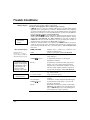
Trouble Conditions
"Check" and
"Battery" Displays
* Not all systems
use wireless
sensors.
Other Trouble Displays
Words or letters in
parentheses ( ) are those
that are displayed on FixedWord/Icon Display keypads.
The word CHECK on the keypad's display, accompanied by a "beeping" at the
keypad, indicates a trouble condition in the system.
To silence the beeping for these conditions, press any key.
• "CHECK" and one or more zone numbers indicates that a problem exists with the
displayed zone(s) and requires your attention. Determine if the zone(s) displayed
are intact and make them so if they are not. If the problem has been corrected, the
display can be cleared if you enter the OFF sequence (security code plus OFF key)
twice. If the display persists, CALL FOR SERVICE.
NOTE: CHECK
70 on Fixed-Word/Icon Display keypads indicates that the
wiring connection to the external sounder is faulted (opened or shorted), and you
should CALL FOR SERVICE. See “BELL FAILURE” on next page. A display of
CHECK 90 indicates that RF interference may be preventing the operation of
wireless sensors* in the system. See “Rcvr Jam” on next page.
• If there are wireless sensors* in your system, the CHECK condition may also be
caused by some change in the environment that prevents the wireless receiver
from receiving communication from a particular sensor. CALL FOR SERVICE if
this occurs.
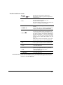
COMM. FAILURE
(or FC)
SYSTEM LO BAT
(or BAT
* Any “beeping” that
accompanies a trouble
display can be stopped
by depressing any key
on the keypad or by
entering an OFF
sequence (code + OFF)
with no
zone No.)
Tamper
** Not all systems use
wireless sensors.
+ 1 + device number
LO BAT
+ zone descriptor
(or BAT
with
zone No.)
.
– 22 –
Indicates that a failure has occurred in the
telephone communication
portion of your system. CALL FOR SERVICE.
Indicates that a low system battery condition
exists. Display is
accompanied by "beeping"* at the keypad.
Depending on installer
programming, a system low battery may prevent
arming, or you may need to perform the arming
sequence twice to override the condition (see your
installer). If this condition persists for more than
one day (with AC present), CALL FOR SERVICE.
If programmed, indicates a tamper fault condition
(e.g., cover removed)
exists at the device shown.
Indicates that there is a low battery condition in the
wireless
transmitter** number displayed (00 is RF keypad).
Accompanied by a single "beep"* (once every 40
seconds) at the keypad.
Either replace the battery yourself, or CALL FOR
SERVICE. If the battery is not replaced within 30
days, a CHECK display may occur indicating that
the transmitter is no longer operating.
Trouble Conditions (cont’d)
Rcvr Jam
(or CHECK
90)
MODEM COMM
(or CC)
BELL FAILURE
(or CHECK 70)
AC LOSS
(or NO AC
Wireless part of the system is experiencing
RF interference which may prevent reception from
wireless sensors.**
Indicates that the control is on-line with
the Central Monitoring Station's or your
installer’s remote computer.
The control will not operate while on-line. Wait a few
minutes — the display should disappear.
Indicates that the wiring connection to the external
sounder
is at fault (open or shorted). Accompanied by
“beeping” at the keypad. CALL FOR SERVICE.
The system is only operating on battery power due
to an AC power failure. If only some lights are out
)
Busy-Standby
(or dI)
on the premises, check circuit breakers and fuses
and reset or replace as necessary. Depending on
installer programming, an AC loss may prevent
arming, or you may need to perform the arming
sequence twice to override the condition (see your
installer).
If AC power cannot be restored and a “low system
battery” message appears, CALL FOR SERVICE.
If this message remains displayed for more than 1
minute, system is disabled. CALL FOR SERVICE.
OPEN CIRCUIT
(or OC)
The keypad is not receiving signals from the control.
CALL FOR SERVICE.
Long Rng Trbl
If installed, the back-up communications media
portion of your system has failed (e.g., internet,
intranet networks, long range radio).
CALL FOR SERVICE.
(or bF)
TELCO FAULT
(or CHECK 94)
The telephone line has a problem.
CALL FOR SERVICE.
Total Power Failure If there is no keypad display at all, and the READY indicator is not lit, operating
power (from AC and back-up battery) for the system has stopped and the system is
inoperative. CALL FOR SERVICE.
– 23 –
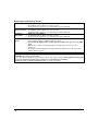
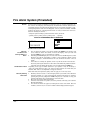
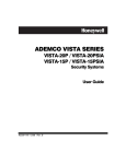
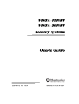
Fire Alarm System (If Installed)
General
Your fire alarm system (if installed) is on 24 hours a day, for continuous protection. In
the event of an emergency, the strategically located smoke and heat detectors will
sound their alarms and automatically send signals to your system, triggering a loud,
interrupted pulsed sound* from the Keypad(s) and any external sounders. A FIRE
message will appear at your Keypad and remain on until you silence the alarm (see
below for silencing fire alarms).
* Temporal pulse sounding is produced for Fire alarms, as follows:
3 pulses–pause–3 pulses–pause–3 pulses–pause. . . , repeated.
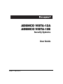
TYPICAL FIRE EMERGENCY DISPLAYS
FIRE 01
STOCK ROOM
ALPHA DISPLAY KEYPAD
Silencing
Fire Alarms and
Clearing Memory of
Alarm
1.
2.
3.
Smoke Detector Reset
Manually Initiating
a Fire Alarm
ALARM
FIRE
FIXED-WORD KEYPAD
You can silence the alarm at any time by pressing the OFF key (the security code
is not needed to silence fire alarms). To clear the display, enter your code and
press the OFF key again (to clear Memory of Alarm).
If the Keypad's FIRE display does not clear after the second OFF sequence, smoke
detectors may still be responding to smoke or heat producing objects in their
vicinity. Investigate, and should this be the case, eliminate the source of heat or
smoke.
If this does not remedy the problem, there may still be smoke in the detector.
Clear it by fanning the detector for about 30 seconds. When the problem has been
corrected, clear the display by entering your code and pressing the OFF key.
Depending on the type of smoke detectors in your system, it may be necessary to
"reset" the smoke detectors after a fire alarm has been turned off. Check with your
installer. This "reset" is accomplished at a keypad, as follows:
Enter User Code, then press the [1] key (does not apply to an “arm only” user).
1.
2.
3.
4.
– 24 –
01
AC
Should you become aware of a fire emergency before your smoke or heat detectors
sense the problem, go to your nearest keypad and manually initiate an alarm by
pressing the panic key assigned for FIRE emergency for 2 seconds. If a key pair
has been assigned for fire, press both keys at the same time.
Evacuate all occupants from the premises.
If flames and/or smoke are present, leave the premises and notify your local Fire
Brigade immediately.
If no flames or smoke are apparent, investigate the cause of the alarm. The zone
number(s) of the zone(s) in an alarm condition will be displayed at the keypad.
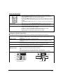
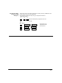
Using the Panic Key(s)
Assigned for FIRE
Emergency
A key or key pair may have been assigned for manually initiating a FIRE alarm. See
the Panic Keys section for key assignments.
For convenience, indicate the key or key pair assigned for fire below.
Individual Keys
A
B
C
Press the individual key assigned for fire for 2seconds.
OR
Key Pairs
1 OFF
∗READY
3 STAY
and
and
and
∗READY
Press the key pair
assigned for fire at
the same time.
#
#
– 25 –
Quick Guide to Basic System Functions
FUNCTION
PROCEDURE
COMMENTS
Check Zones
Press READY key.
View faulted zones when system not
ready.
Arm System
Enter code. Press arming key desired:
(AWAY, STAY, NIGHT-STAY (Internal),
MAXIMUM, INSTANT)
Arms system in mode selected.
Quick Arm
(if programmed)
Press #. Press arming key desired:
(AWAY, STAY, MAXIMUM, INSTANT)
Arms system in mode selected, quickly
and without use of a code.
Bypass Zone(s)
Enter code. Press BYPASS key.
Enter zone number(s) to be bypassed
(use 2-digit entries).
Bypassed zones are unprotected and will
not cause an alarm if violated.
Quick Bypass
(if programmed)
Enter code. Press BYPASS key + [#].
Bypasses all faulted zones automatically.
Enter code. Press OFF key.
Also disarms system. Memory of alarm
remains until cleared.
Press OFF key.
Press any key.
Memory of Alarm remains until cleared.
Determine cause.
Disarm System
Enter code. Press OFF key.
Also silences sounders. Memory of alarm
remains until cleared.
Clear Alarm Memory
After disarming, enter code again.
Press OFF key again.
Keypad beeps rapidly on entry if alarm
has occurred while absent. Alarm display
will remain upon disarming until
cleared.
Duress (if active
and connected to
Central Station)
Arm or disarm "normally", but
use your 4-digit Duress code to do so.
Performs desired action and sends silent
alarm to Central Station.
Panic Alarms
(as programmed)
Press key [A], [B], or [C] for at least 2
seconds or briefly press assigned key pair.
See the Panic Keys section for emergency
functions programmed for your system.
Note: Keys “A”, “B”, and “C” may have
been programmed for other functions.
Chime Mode
To turn ON or OFF: Enter code. Press
CHIME key.
The keypad will sound if selected doors
or windows are violated while system is
disarmed and chime mode is ON.
Test Mode
To turn ON: Enter code. Press TEST + [0].
To turn OFF: Enter code. Press OFF key.
Tests alarm sounder and allows sensors
to be tested.
Phone Access
if applicable
Consult Phone Access User's Guide that
accompanies the Phone Module.
Permits system access remotely, via
multifrequency phone.
Silence Sounders
Burglary:
Fire:
"Check":
– 26 –
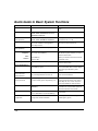
Charts of Your System’s Features
System Features
Features
Comments
Exit Delay (seconds)
Part. 1:
Part. 2:
Common Part: Same as Part. 1
Entry Delay 1 (seconds)
Part. 1:
Part. 2:
Common Part: Same as Part. 1
Entry Delay 2 (seconds)
Part. 1:
Part. 2:
Common Part: Same as Part. 1
Night-Stay (internal) Zones
Zones:
Quick Arm
yes
no
Quick Bypass
yes
no
Follow-Me
yes
no
users:
Keyswitch Arming
Arm AWAY:
steady
flash
(circle type of LED lighting)
Arm STAY:
steady
flash
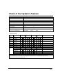
Function Keys
Option
01
02
03
04
05
06
07
08
09
10
00
Function
A
P1 P2 P3
B
P1 P2 P3
C
P1 P2 P3
D
P1 P2 P3
Paging
Time Display
Arm AWAY
Arm STAY
Arm NIGHTSTAY
Step Arming
Device Activation
Comm. Test
Comments
Device:
Macro Key 1†
Macro Key 2†
Emergency Keys:
Personal
Emergency
Silent Alarm
Audible Alarm
Fire
zone 95
zone 99
zone 96
paging
n/a
n/a
n/a
n/a
Emergency Keys:
A = paired keys [1] / [∗] (zone 95); B = paired keys [∗] / [#] (zone 99); C = paired keys [3] / [#] (zone 96)
† There are only two macros system-wide.
– 27 –
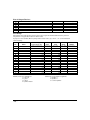
List of Output Devices
Device
01
02
03
04
17
18
Description
Schedule No.
Function Key
User Setup
The following chart will help keep track of system users. Copies should be distributed to the partition 1
and partition 2 (if applicable) masters for their records.
To program a user attribute: Enter system/partition master code + [8] + user no. + “#” command listed in
column heading…
User
No.
User
Name
01
02
03
04
05
06
07
08
09
10
11
12
13
14
15
16
17
installer
system master
partition 1 master
User’s Part(s).†
(system master only)
Security
Code
Auth.
Level
Access
Group
RF Zone
Number
[#] [3] +[0] + part(s) + [#]
enter new code
[#] [1] + level
[#] [2] + group
[#] [4] + zone no.
Authority Levels: 0 = standard user
1 = arm only
2 = guest
3 = duress
4 = partition master
– 28 –
(all)
(all)
(1)
(1)
(1)
(1)
(1)
(1)
(1)
(1)
(1)
(1)
(1)
(1)
(1)
(1)
(1)
installer
master
(4)
(0)
(0)
(0)
(0)
(0)
(0)
(0)
(0)
(0)
(0)
(0)
(0)
(0)
(0)
Partitions: 0 = clears partition assignments
1 = partition 1
2 = partition 2
3 = common partition
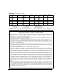
Schedules: master code + [#] + [6] [4].
No.
Event
Device No.
Access
Group
Partition
Start
Stop
Repeat
Random
(see list
below)
for “01” events:
(see device list
below)
for “02” events:
enter 1-8
for “04-06”
events: enter
1, 2, or 3
Time/
Day
Time/
Day
(1-4)
(yes/no)
01
02
03
04
Events:
00 = remove event
03 = child not home report
06 = auto disarm
01 = device on/off
04 = STAY arm
07 = display “reminder”
02 = user access
05 = AWAY arm
08 = disarm time window
Repeat Options: 0 = none; 1 = repeat weekly; 2 = repeat every other week; 3 = repeat every third week; 4 = repeat every fourth week
WARNING!
THE LIMITATIONS OF THIS ALARM SYSTEM
While this system is an advanced design security system, it does not offer guaranteed protection against
burglary or other emergency. Any alarm system, whether commercial or residential, is subject to compromise or
failure to warn for a variety of reasons. For example:
• Intruders may gain access through unprotected openings or have the technical sophistication to bypass an
alarm sensor or disconnect an alarm warning device.
• Intrusion detectors (e.g.,, passive infrared detectors), smoke detectors, and many other sensing devices will not
work without power. Battery operated devices will not work without batteries, with dead batteries, or if the
batteries are not put in properly. Devices powered solely by AC will not work if their AC power supply is cut
off for any reason, however briefly.
• Signals sent by wireless transmitters may be blocked or reflected by metal before they reach the alarm
receiver. Even if the signal path has been recently checked during a weekly test, blockage can occur if a metal
object is moved into the path.
• A user may not be able to reach a panic or emergency button quickly enough.
• While smoke detectors have played a key role in reducing residential fire deaths, they may not activate or
provide early warning for a variety of reasons in as many as 35% of all fires. Some of the reasons smoke
detectors used in conjunction with this System may not work are as follows. Smoke detectors may have been
improperly installed and positioned. Smoke detectors may not sense fires that start where smoke cannot reach
the detectors, such as in chimneys, in walls, or roofs, or on the other side of closed doors. Smoke detectors also
may not sense a fire on another level of a residence or building. A second floor detector, for example, may not
sense a first floor or basement fire. Moreover, smoke detectors have sensing limitations. No smoke detector
can sense every kind of fire every time. In general, detectors may not always warn about fires caused by
carelessness and safety hazards like smoking in bed, violent explosions, escaping gas, improper storage of
flammable materials, overloaded electrical circuits, children playing with matches, or arson. Depending upon
the nature of the fire and/or the locations of the smoke detectors, the detector, even if it operates as
anticipated, may not provide sufficient warning to allow all occupants to escape in time to prevent injury or
death.
• Passive Infrared Motion Detectors can only detect intrusion within the designed ranges as diagrammed in
their installation manual. Passive Infrared Detectors do not provide volumetric area protection. They do
create multiple beams of protection, and intrusion can only be detected in unobstructed areas covered by those
beams. They cannot detect motion or intrusion that takes place behind walls, ceilings, floors, closed doors,
glass partitions, glass doors, or windows.
– 29 –
Mechanical tampering, masking, painting or spraying of any material on the mirrors, windows or any part of
the optical system can reduce their detection ability. Passive Infrared Detectors sense changes in temperature;
however, as the ambient temperature of protected area approaches the temperature range of 32° to 40°C, the
detection performance can decrease.
• Alarm warning devices such as sirens, bells or horns may not alert people or wake up sleepers if they are
located on the other side of closed or partly open doors. If warning devices sound on a different level of the
residence from the bedrooms, then they are less likely to waken or alert people inside the bedrooms. Even
persons who are awake may not hear the warning if the alarm is muffled from a stereo, radio, air conditioner
or other appliance, or by passing traffic. Finally, alarm warning devices, however loud, may not warn hearingimpaired people or waken deep sleepers.
• Telephone lines needed to transmit alarm signals from a premises to a central monitoring station may be out
of service or temporarily out of service. Telephone lines are also subject to compromise by sophisticated
intruders.
• Even if the system responds to the emergency as intended, however, occupants may have insufficient time to
protect themselves from the emergency situation. In the case of a monitored alarm system, authorities may
not respond appropriately.
• This equipment, like other electrical devices, is subject to component failure. Even though this equipment is
designed to last as long as 10 years, the electronic components could fail at any time.
The most common cause of an alarm system not functioning when an intrusion or fire occurs is inadequate
maintenance. This alarm system should be tested weekly to make sure all sensors and transmitters are working
properly.
Installing an alarm system may make one eligible for lower insurance rates, but an alarm system is not a
substitute for insurance. Homeowners, property owners and renters should continue to act prudently in
protecting themselves and continue to insure their lives and property.
We continue to develop new and improved protection devices. Users of alarm systems owe it to themselves and
their loved ones to learn about these developments.
– 30 –
ONE YEAR LIMITED WARRANTY
Honeywell International Inc., acting through its Security & Custom Electronics business ("Seller"), 165
Eileen Way, Syosset, New York 11791, warrants its security equipment (the "product") to be free from
defects in materials and workmanship for one year from date of original purchase, under normal use
and service. Seller's obligation is limited to repairing or replacing, at its option, free of charge for parts,
labor, or transportation, any product proven to be defective in materials or workmanship under normal
use and service. Seller shall have no obligation under this warranty or otherwise if the product is
altered or improperly repaired or serviced by anyone other than the Seller. In case of defect, contact the
security professional who installed and maintains your security equipment or the Seller for product
repair.
This one year Limited Warranty is in lieu of all other express warranties, obligations or liabilities.
THERE ARE NO EXPRESS WARRANTIES, WHICH EXTEND BEYOND THE FACE HEREOF. ANY
IMPLIED WARRANTIES, OBLIGATIONS OR LIABILITIES MADE BY SELLER IN CONNECTION
WITH THIS PRODUCT, INCLUDING ANY IMPLIED WARRANTY OF MERCHANTABILITY, OR
FITNESS FOR A PARTICULAR PURPOSE OR OTHERWISE, ARE LIMITED IN DURATION TO A
PERIOD OF ONE YEAR FROM THE DATE OF ORIGINAL PURCHASE. ANY ACTION FOR
BREACH OF ANY WARRANTY, INCLUDING BUT NOT LIMITED TO ANY IMPLIED WARRANTY
OF MERCHANTABILITY, MUST BE BROUGHT WITHIN 12 MONTHS FROM DATE OF ORIGINAL
PURCHASE. IN NO CASE SHALL SELLER BE LIABLE TO ANYONE FOR ANY CONSEQUENTIAL
OR INCIDENTAL DAMAGES FOR BREACH OF THIS OR ANY OTHER WARRANTY, EXPRESS OR
IMPLIED, OR UPON ANY OTHER BASIS OF LIABILITY WHATSOEVER, EVEN IF THE LOSS OR
DAMAGE IS CAUSED BY THE SELLER'S OWN NEGLIGENCE OR FAULT. Some states do not allow
limitation on how long an implied warranty lasts or the exclusion or limitation of incidental or
consequential damages, so the above limitation or exclusion may not apply to you.
Seller does not represent that the product may not be compromised or circumvented; that the product
will prevent any personal injury or property loss by burglary, robbery, fire or otherwise; or that the
product will in all cases provide adequate warning or protection. Buyer understands that a properly
installed and maintained alarm may only reduce the risk of a burglary, robbery, fire or other events
occurring without providing an alarm, but it is not insurance or a guarantee that such will not occur or
that there will be no personal injury or property loss as a result. CONSEQUENTLY, SELLER SHALL
HAVE NO LIABILITY FOR ANY PERSONAL INJURY, PROPERTY DAMAGE OR OTHER LOSS
BASED ON A CLAIM THE PRODUCT FAILED TO GIVE WARNING. HOWEVER, IF SELLER IS
HELD LIABLE, WHETHER DIRECTLY OR INDIRECTLY, FOR ANY LOSS OR DAMAGE ARISING
UNDER THIS LIMITED WARRANTY OR OTHERWISE, REGARDLESS OF CAUSE OR ORIGIN,
SELLER'S MAXIMUM LIABILITY SHALL NOT IN ANY CASE EXCEED THE PURCHASE PRICE
OF THE PRODUCT, WHICH SHALL BE THE COMPLETE AND EXCLUSIVE REMEDY AGAINST
SELLER. This warranty gives you specific legal rights, and you may also have other rights which vary
from state to state. No increase or alteration, written or verbal, to this warranty is authorized.
– 31 –
165 Eileen Way, Syosset, New York 11791
Copyright © 2004 Honeywell International Inc.
www.honeywell.com/security
ÊK10021-1~Š
K10021-1 9/04 Rev. A