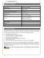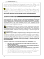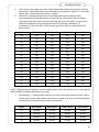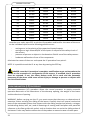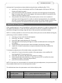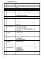
1
LH100
LH140
AUTOMATED SYSTEMS FOR SLIDING DOORS
INSTALLATION MANUAL
ENGLISH
SESAMO DUALCORE
Thank you for choosing this product. So that you get the most out of your automated system, Sesamo
recommends you read and follow the installation and usage instructions in this manual carefully. This
automated system must only be installed by professional technicians, for whom this manual is
intended. Improper installation can present a hazard for persons and objects. The packaging material
(wood, plastic, cardboard, etc.) must be disposed of properly and must be kept out of the reach of
children as they present a potential hazard. Each phase of installation must be carried out in accordance
with current regulations and must in any case good working practice must be employed. Before
beginning installation, ensure that the product is intact and has not been damaged during
transportation or storage. Before installing the product, ensure that all architectonic and structural
elements of the doorway (installation points for automated systems, fixtures, etc.) are suitable and
strong enough to be automated. The door being automated must have a smooth opening and closing
action without resistance. Carry out a careful risk assessment and make any modifications necessary to
eliminate crushing or shearing zones and eliminate hazards in general. Never install the product in
environments containing flammable gas, vapours or fumes. The manufacturer of the automated system
is not responsible for failure to observe good technical practise or specific regulations in the
construction of fixtures to be motorised or failures of these parts. All safety devices for the automatic
door (e.g.: active infra-red sensors) must be installed in accordance with the regulations and directives
in force, the risk assessment undertaken, the type of system, use, traffic, forces and inertia in play.
Always pay particular attention to areas in which the following may occur: crushing, shearing and any
other danger, posting suitable warning signs if necessary. Include the identification data of the
motorised door on each installation. Check that the electrical network to which the system is corrected
is of the right size and has suitable protections (differential switch and surge protection). Only use
original spare parts for maintenance or repairs. Do not tamper with or alter the internal equipment of
the automated system or the safety devices present in the control CPU. The manufacturer denies any
responsibility of internal parts on the automated system are tampered with or altered or if safety
devices different to those indicated by the manufacturer are used. The technician installing the
automated system must provide the person responsible for the automatic door with the user manual
and any information necessary to use the door in automatic mode and in case of emergency. Pay
particular attention to the messages in this manual identified by the hazard symbol. These may be
warnings with the aim of avoiding potential damage to the equipment or specific warnings of potential
hazards for the safety of the installation technician or other personnel. This device has been designed
for the automation of sliding pedestrian doors. Any other use is considered contrary to the use intended
by the manufacturer, who will therefore accept no liability for the consequences.
Before performing any operation on the machine, read this manual carefully and
follow the instructions, paying particular attention to the areas with the
following warnings:
DANGER:
WARNING:
instructions that, if not followed scrupulously, could cause
dangerous or potentially fatal situations
instructions that, if not followed scrupulously, could cause
malfunctions
3
SESAMO DUALCORE
SUMMARY
summary .......................................................................................................................... 4
machines directive ........................................................................................................... 5
technical specifications .................................................................................................... 6
set up for installation ....................................................................................................... 6
description of components fig1 - fig5............................................................................... 7
case wall fixing ................................................................................................................. 7
heights for case fixing ....................................................................................................... 8
installation of carriages .................................................................................................... 9
leaf adjustment .............................................................................................................. 10
mounting and tensioning the belt fig.12 ........................................................................ 11
preparing the carriages fig.5 - fig.9 ................................................................................ 11
regulation of the leaf limit switch fig.5 - fig.13............................................................... 12
installation of the electric lock (optional) fig.16 - 16a ................................................... 12
installation of the emergency release (optional) fig. 17 to 19 ....................................... 12
cover fixing ..................................................................................................................... 13
mechanical assembly final checks .................................................................................. 13
Dualcore processor: function and warnings ................................................................... 14
description of the electronic processor.......................................................................... 15
processor/sensors compliant with EN16005 .................................................................. 16
terminal connections from fig.23 to 28 .......................................................................... 18
activation of automated system..................................................................................... 19
learn sensor procedure (LS) ........................................................................................... 20
learn parameters (LP) procedure ................................................................................... 22
parameters setting mode: .............................................................................................. 23
diagnostics...................................................................................................................... 26
turning on/reset/delivery ............................................................................................... 28
4
SESAMO DUALCORE
MACHINES DIRECTIVE
The technician installing the motorisation of a door becomes the constructor of the automatic door in
accordance with directive 2006/42/CE and must:
-
Provide the Technical File with the documents indicated in appendix VII of the Machines
Directive and save them for at least 10 years.
Edit the CE declaration of conformity according to appendix II-A of the machines directive
and issue a copy to the user.
Affix the CE mark to the motorised door in accordance with point 1.7.3 of appendix I of the
machines directive.
In particular, but not exclusively, if under regulation EN16005 it becomes necessary to install
a monitored sensor/s, it must be connected and set up as described in this manual (see pp.
16-17), checking that they operate correctly as described in the manual of the sensor/s used.
For additional information and to assist the installation technician in applying the prescriptions of the
European Directives and Regulations regarding the safe use of motorised doors, consult the guidelines
available on the internet at the address www.sesamo.eu
DECLARATION OF INCORPORATION (DIRECTIVE 2006/42/CE, APPENDIX II, PART B)
Manufacturer:
SESAMO S.R.L.
Str. Gabannone 8/10 - 15030 Terruggia - AL
Address:
Declares that:
The product DUALCORE LH100/LH140
- is made to be incorporated in a machine to construct a machine considered by Directive 2006/42/CE
- conforms with the essential safety requirements indicated in appendix I of the directive with the
exception of the following points: 1.2.4.3, 1.2.4.4, 1.3.4, 1.3.5, 1.3.7, 1.3.8.2, 1.4, 1.5.3, 1.5.7, 1.5.14,
1.5.15, 1.5.16
- complies with the conditions of the following other CE Directives: 2004/108/CE Electromagnetic
Compatibility, 2006/95/CE Low Voltage
and that
- the following (parts/clauses of) agreed regulations have been applied:
EN 61000-6-2
EN 50366
EN 61000 -6–3
EN16005
EN 60335-1
and also declares that:
- the relevant technical documentation has been completed in accordance with part B of appendix VII;
this documentation, or parts of it, will be delivered electronically or by traditional post upon justified
request from the competent national authorities
- the relative technical documentation will be compiled by: SESAMO SRL, Strada Gabannone, 8/10 15030 Terruggia (AL) - Italy
- it is not permitted to use the product until the machine in which it will be incorporated or will become
a component of has been identified and has received the declaration of conformity with the conditions
of Directive 2006/42/CE and the national legislation that transposes it, in other words, until the
machinery referred to in this declaration forms a single unit with the machine.
SESAMO S.R.L.
February 2014
Aldo Amerio
(Administrator)
5
SESAMO DUALCORE
TECHNICAL SPECIFICATIONS
DIMENSIONS
See Fig.1
POWER SUPPLY
230V ±10% AC 50/60Hz
LH100 = 150 W
LH140 = 180 W
15Vdc - 12W MAX
NOMINAL POWER
POWER SUPPLY OF EXTERNAL DEVICES
OPERATING TEMPERATURE
24V 1.3Ah
1 Leaf =70cm/s
2 Leaves =140 cm/s
1 Leaf = 700 ÷ 3000 mm
2 Leaves = 800 ÷ 3000 mm
LH100 1 Leaf = 140 kg
LH100 2 Leaves 100+100 kg
LH140 1 Leaf = 160 kg
LH140 2 Leaves = 140+140 kg
-10°C +55°C
ANTI-CRUSHING
Automatic force limitation in presence of obstacles
WEIGHT
11 kg/m approximately
SERVICE
PROTECTION
Continual
IP20
EMERGENCY BATTERY POWER SUPPLY
OPENING SPEED
DOORWAY
CAPACITY
SET UP FOR INSTALLATION
The automated system is designed to operate with a variety of accessory and peripheral
configurations. Fig.4 shows a complete installation example which highlights the possible
access points in the automation case for connecting the following peripherals:
ABCDEFG-
Left safety sensor in opening
Internal safety sensor in closing and control
External safety sensor in closing and control
Right safety sensor in opening
Differential switch (230Vac network power supply)
Operating logic selector
Electric lock manual release lever (Optional, only if electric lock included)
Set up access points to the interior of the automated system to enable the connection of
external peripherals. To pass the power chords through, use the conduct on the head or
construct one in the aluminium profile as shown in fig. 29. Protect the power chord with the
rubber washer provided.
DANGER: take care not to damage the power chord during the installation described.
6
SESAMO DUALCORE
DESCRIPTION OF COMPONENTS FIG1 - FIG5
The automated system consists of the following elements (ref. fig.1 and fig.5):
ABCDEFGHIJKLMNP-
extruded aluminium case
extruded aluminium slide rail
anti-vibration rubber for slide rail
extruded aluminium cover
brush (Optional, available in 3 sizes)
extruded aluminium filler profile (Optional)
electronic control unit
geared motor with encoder
belt support and tensioner device
emergency battery module
electric lock (Optional)
leaf limit switch
adjustable carriages with wheels and anti-derailing roller
belt attachment with toothed traction belt
n.1 acknowledgement for electric lock (Optional)
CASE WALL FIXING
DANGER: the phases of installation and fixing of the automated system involves the
movement of heavy parts and tools at heights greater than 2 or 3 meters. Accidental
falling of the heavy tools and parts presents a high risk to personnel and objects in the
vicinity. To reduce this risk, before performing the installation or maintenance, cordon off
a safe zone around the working area and prohibit access to any personnel not involved in
the operation and remove any objects that may be damaged. To reduce the risk to the
personnel in charge of the operations, the personnel must wear personal protective
equipment, in particular a helmet, safety shoes and cut-resistant gloves.
Remove the screws then remove the cover following the sequence shown in fig.7.
Remove the carriages following the procedure below:
-
disconnect the belt attachment bracket from the carriage ref.A fig.11 by undoing
screws C.
loosen the screw of the anti-derailing roller ref.D fig.9 and lower it fully.
remove the carriage
To make it easier to fix the case to the wall, the internal components can be moved or
removed by undoing the screws that attach it to the screw channel on the roof of the
automated system, as shown in Fig.6.
WARNING: before moving or removing the internal components, note their positions
or trace markers on the case so that they are reinstalled in the correct positions.
7
SESAMO DUALCORE
Inspect the surface to which the case will be fixed. If the surface is not sufficiently smooth,
level it using spacers. If the crossbeam of the automated system is fixed to an irregular
surface it could cause it to deform.
Ensure that the structure to which the case and subsequently the sliding leaves will be fixed
is strong enough and well anchored to the building.
Fix the case to the support via the hexagonal screws M8, of a suitable length, through the
eyelets provided (fig.8). Ensure the screws and washers are suitable for use with the
material of the structure to which the case is being fixed.
DANGER: failure to observe the indications relating to fixing the case to the wall can
compromise the stability of the fixture, causing it to detach from the wall and parts to fall.
It is important to perform a careful assessment of the support structure, the hold of the
screws or washers and to stop the installation and perform further assessments if in any
doubt.
WARNING: the case must be fixed using all the eyelets/holes provided in the
aluminium case.
DANGER: before tightening the case fixing screws, ensure that the crossbeam is
level in length and depth as shown in fig.8. Positioning errors that exceed those indicated
in fig.8 can compromise the proper functioning of the automated system and present a
safety risk.
HEIGHTS FOR CASE FIXING
For two leaf doors, the automated system must be centred in the doorway so that the two
leaves meet in the centre of the opening (Fig. A).
For single leaf doors, follow the indications and machine heights indicated in Fig. B.
Extendible crossbeams (unused areas of the case) should be positioned with the extensions
added to the QMC and QMT.
For the abbreviations used in fig.A and B refer to the list below:
•
•
•
•
•
•
Lup: Usable doorway width:
A: Sliding leaf width
St: Mount over leaf
Sc: Mount below leaf
T : Total case length
QMC : Thickness of side covers 5mm approx.
The crossbeams must be positioned at the heights shown in figures 1, 2 and 3 and the
following tables in relation to the type of profile selected for the leaves:
8
SESAMO DUALCORE
SIZE
HAS
HCO
HUP
HCA
IH
SIZE
HAS
HCO
HUP
HCA
IH
DESCRIPTION
Height of sliding leaf
Height above ground below cover
Usable height of doorway
Height above ground of case bottom
Play in height (suggested value 5mm)
PROFILES
SESAMO PROFILES
COMMERCIAL (FIG.1)
MAGNUM (FIG.2)
= HUP + 8
= HUP
= HCO
= HUP + 40 mm
-
SESAMO PROFILES
= HUP + 9
= HUP + 6
= H – 152 - IH
TWENTY (FIG.3)
= HUP + 8
= HUP
= H -125 -IH
= HUP + 46
5 mm
= HUP + 40
5 mm
INSTALLATION OF CARRIAGES
DANGER: carefully check the weight of the leaves to ensure they are within the
maximum capacity of the automated system; in case of doubt, do not proceed beyond the
installation phase; if leaves with weights near to the capacity limits are installed, more
frequent maintenance intervals and periodical checks to assess the state of wear of the
components must be adopted; always replace parts that show even slight signs of wear.
Fix the carriages to the leaves in the positions shown in fig.5
The positions shown in fig.5 depict the leaf seen from the inspection side (cover) of the
automated system.
To fix the leaf, use M8 screws (fig.9 part.F) with hexagonal heads with suitable flat and
toothed washers.
NOTE: for leaves equipped with a 'break glass' emergency system or glass leaves equipped
with clamps, use the mounting positions shown in the manuals of the relative accessories.
DANGER: incorrect installation could compromise the correct functioning of the
automated system and present a risk.
Ensure that the anti-derailing wheels (fig.9 ref.E) are fully lowered. Lift the leaf and place the
wheels of the carriages delicately on the guide rail, taking care not to damage the parts by
dropping or banging them.
9
SESAMO DUALCORE
LEAF ADJUSTMENT
The leaves can be adjusted on three axes (x,y,z) according to the requirements of the
installation.
LATERAL ADJUSTMENT (Y) FIG.9 - FIG.10
loosen the screws F and slide the leaf along the Y axis to the position where it will operate
correctly.
Take care to align the carriages correctly and ensure they are parallel to the guide rail, as
shown in Fig.10. To check the correct alignment, ensure that the distances "E" measured
between the leaf and the carriage are the same for all the carriages on both the left and
right sides. To further check the alignment, move the leaves manually: they should slide
with the minimum of effort without any impediment or abnormal friction. When the leaves
are in the correct position, tighten the screws F progressively, alternating between different
screws until they are all fully tightened.
WARNING: turning the screws F when tightening can cause the carriage to go out of
alignment. To avoid this, tighten alternate between screws F and tighten progressively.
WARNING: incorrect alignment of the carriages in the guide rail can cause excessive
wear, noise and malfunctions in the automated system.
VERTICAL ADJUSTMENT (Z) FIG.9
To adjust the height of the leaves and ensure they are perfectly perpendicular to the floor,
proceed as follows (ref.fig.9):
-
Loosed screws G slightly.
DANGER: do not undo the screws G fully as the leaf could fall.
-
Use the level screws H to adjust the height of the leaf
Tighten the screws G taking care not to alter the alignment.
HORIZONTAL ADJUSTMENT (X) FIG.11
necessary to adjust the meeting point of the two leaves which must be near the centre of
the doorway. Automated systems are supplied with the components positioned to make the
leaves meet in the centre of a doorway. If it is necessary to change the meeting point during
installation, proceed as follows (ref. fig.11):
-
10
Loosen screws D relating to the clamp A on the passing branch of the belt (i.e. the
one without joint) so that the comb B allows the belt E to be moved.
Move the clamp to the desired position
Tighten the screws D, ensuring that the teeth of the belt E sit correctly in the slots
in the comb B
SESAMO DUALCORE
MOUNTING AND TENSIONING THE BELT FIG.12
to adjust the tension of the belt, proceed as follows (ref.fig.12):
-
-
ensure that the motor group is positioned and fixed according to the default setup and is in a position that ensures the belt is centred in the running area.
ensure that the nuts D are loosened so that the entire unit can be moved laterally
ensure that screw E is loosed and does not compress spring F
ensure that the nuts B are loosed so that slider A is free to move
place the toothed belt over the motor pulley and the conduct pulley.
move the support unit C to the left until the belt is under a first level of tension.
Check that the two belt branches are visibly taut (without sag)
tighten the nuts D of the pulley group on the case
turn screw E until the spring F is almost completely compressed (the spirals should
almost be touching). The length of the compressed spring should be between 1112 mm.
Tighten screws B
PREPARING THE CARRIAGES FIG.5 - FIG.9
Fix the belt clamps part.N fig.5 to the carriages using the screws provided and match the
positions indicated in fig.5 for 1 or 2 leaves.
Adjust the anti-derailing device part.E fig.9 via the screws part.D fig.9 so that the roller is not
in contact with the aluminium profile when sliding,
maintaining a play of 0.5-1 mm fig.9a. Tighten screw D fig.9 without affecting the
adjustment.
Check that all the screws on the carriages are correctly tightened.
DANGER: lose screws on the carriages can come undone allowing parts to become
detached, causing the leaves to fall or the belt to come off, leading to the leaf being out of
control when in movement and presenting a serious risk of injury.
WARNING: incorrect adjustment of the anti-derailing device that leaves the wheel in
contact with the aluminium profile causes excessive wear and noise during operation.
11
SESAMO DUALCORE
REGULATION OF THE LEAF LIMIT SWITCH FIG.5 - FIG.13
Position the limit switches of the leaves as shown in fig.5, checking that for two leaf
systems, the central limit switch only acts on the right leaf (reference from cover side):
-
position the rubber plug fig.13 part.B in the side of the bracket part.A in contact
with the carriage
adjust the position of the bracket A, loosening the screws C and moving the nuts
into the channel
when the limit switches are in position, tighten screws C
DANGER: before operating the automated system, check that the screws of the limit
switches are tightened properly part.C fig.13
INSTALLATION OF THE ELECTRIC LOCK (OPTIONAL) FIG.16 -
16A
install the electric lock in the automated system using the screws provided in the
screw channel of the case as shown in fig.16
check that the acknowledgement slide on the carriage part.P fig.5 is positioned as
shown in fig.5 according to the type of doorway
close the leaf/leaves completely
move the electric lock until the lock rod B fig.16a is approximately 2mm from the
acknowledgement slide A fig.16a on the carriage, then tighten the nuts of the
electric lock
INSTALLATION OF THE EMERGENCY RELEASE (OPTIONAL) FIG. 17 TO 19
attach the release cable to the electric lock as follows (fig.17):
-
before installing, ensure that the spring D is correctly inserted in the pipette A
insert the stop B at the end of the cable below bracket C and feed it through the
opening provided
attach spring D between bracket C and F
insert the threaded section E of the pipette A of the compartment in bracket F
tighten nut G fully
adjust the sheath to reach the position in which you wish to install the release lever. This
can be attached to the head of the automated system (fig.19) or in an easy to reach point on
the lock or wall. It is possible to position the sheath in the cable compartment of the case
with the cable ties provided (fig.14).
DANGER: the sheath must be positioned so that it does not have small creases and is
properly fixed to the supports. If the path of the sheath is too complicated or the
attachment too slack, the function of the emergency release system can compromised and
constitute a safety risk.
12
SESAMO DUALCORE
Insert the nut provided (part.B fig.18) in the hole in the lever body (part.A fig.18). Fix the
release lever in its definitive position using the screws provided (part.C fig.18).
Use fig.17a as reference and cut the sheath and cable A measuring against the point of the
lever in the open position. Pull out cable B by around 160mm pulling it from the stop on the
electric lock. Cut the sheath again at the definitive measurement using the tensioner on the
lever as a gauge. Extract the cable which should protrude by around 160 mm from the
sheath.
DANGER: ensure that while cutting the sheath, no obstructions or offcuts are
created that can compromise the sliding of the cable.
Refer to fig.18 and insert the sheath F and cable B in the tensioner E and screw the
tensioner into the hole on the lever. Insert the small barrel G equipped with grain bolts H
ensuring they do not obstruct the hole in the barrel. Insert the cable D into the hole of the
small barrel G. Close the lever and pull lightly on the cable to remove any play. Keeping the
cable taut, tighten the grain bolts H with an Allen wrench H. Check that the release handle
works correctly and that it has sufficient space to open and fully release the electric lock. If
the tension of the cable needs to be adjusted, do so via the tensioner of the lever or the nut
of the pipette on board the electric lock. At the end of the checks, cut the steel cable.
DANGER: carefully test the correct function of the release lever. Any errors could
prevent the release of the leaf in the event of a failure of the electric lock and constitute a
safety risk.
DANGER: the release mechanism must be checked periodically for loose fastenings,
dirt, wear, corrosion or other unexpected phenomena that could compromise the correct
function of the mechanism.
COVER FIXING
Refer to fig.15 and fix the inserting screws A in the holes in the heads.
Alternatively, the cover can be fixed below as follows:
-
make two holes C diameter 5.5 mm beneath the cover 6mm from the ends
fix the cover using 5x10 screws, screwing them into the inserts located in the
heads
MECHANICAL ASSEMBLY FINAL CHECKS
Before operating the automated system, perform the following checks and operations:
• carefully remove any dust or burr residue from the slide rails and carriage wheels
• check that all screws of the components of the automated system are properly tightened
• check the correct tension of the belt
13
SESAMO DUALCORE
• check that the cables are fixed and that no cables run near the transit area of the carriages
or belt
• check that the limit switches are positioned correctly and that the belt clamps do not
knock against the toothed pulleys
• apply a thin layer of standard grease to the bearings on the slide rail and transmission belt
WARNING: The slide rail and transmission belt can work without lubrication without
wear. Nevertheless, lubrication prevents the onset of noise emission if parts are not
perfectly aligned.
WARNING: for the doors to operate correctly, it is important that there are no
mechanical obstructions or friction opposing the movement of the doors in the sliding
area: if in doubt, test the operation by manoeuvring the door manually with a
dynamometer to identify any points of friction.
DUALCORE PROCESSOR: FUNCTION AND WARNINGS
The dualcore processor is designed to manage automated systems produced by Sesamo,
complies with the specifications of EN16005 and can function with peripherals that comply
with the same regulation in order to allow the creation of fully automated doors in line with
the highest safety standards.
The Dualcore processor may only be used for automated systems produced by Sesamo of
the Dualcore series and must be configured and installed by professionally qualified
personnel, following the instructions provided in this manual with particular attention to the
information marked: danger, warning, note.
The Dualcore processor is designed to configure its own operating parameters through selflearning, guaranteeing quick and easy installation.
DANGER: do not wash, disassemble, modify, repair or remove the protective covers
of the electronic components and the Dualcore processor, as this could lead to fatal
electric shock or irreparably damage the product.
DANGER: do not carry out any operation on the Dualcore processor, except for the
adjustments that can be made via the buttons, without first unplugging the power chord
(fig.21 part.L), as this could lead to fatal electric shock or irreparably damage the product.
DANGER: the Dualcore electronic processor is designed to work in products
manufactured by Sesamo according to the precise specifications of the manufacturer. Any
other use not explicitly considered by the manufacturer may expose personnel and or
objects to risks of death or damage of various nature that are unforeseeable by the
manufacturer. As such, these uses are strictly forbidden.
14
SESAMO DUALCORE
DANGER: the Dualcore processor is designed to work in dry environments, sheltered
from any atmospheric elements or the infiltration of water or other liquids. Exposure to
these elements could lead to fatal electric shock or irreparably damage the product.
DANGER: the processor contains parts under high voltage greater than 600V that
pose a risk of fatal electric shock. To avoid this risk, the protective guards must be under
no circumstances removed and liquids must be kept away from the components as they
can cause fatal electric shock or irreparably damage the product.
DESCRIPTION OF THE ELECTRONIC PROCESSOR
The Dualcore electronic processor consists of the following main components to be learned
during installation (fig.21 and 22):
ABCDE-
input for connection to a PC via the optional signal converter produced by Sesamo;
terminal for connections to peripherals and additional accessories;
connector for connection to motor encoder;
connector for motor power supply;
connector for battery connection;
WARNING: check the correct orientation of the battery connector, only use
batteries provided by Sesamo, only use board/battery wiring with fuse protection at
6.3AT. Failure to do so may lead to electric shock, may compromise the protection of
the circuit with the consequent risk of fire or irreparable damage to the product.
FG-
connector for insertion of the optional battery recharge board;
switching power supply; transforms the power supply of the network cable (230Vac)
(part.L) into output tension of 40V for the processor;
DANGER: the switching power supply at point G contains parts under a voltage
of around 600V that pose a risk of fatal shock. Do not remove the protective base and
cover G for any reason, do not splash liquids on these parts, no not insert objects
(especially metal) between the vents in the cover. This could lead to fatal electric
shock or irreparably damage the product.
HIJ-
protection fuses of 1AT located at the switching power supply input;
display with keys for adjusting operating parameters and selecting operating modes;
main key: removable memory stick for internal programming data of the processor;
WARNING: carefully check the mainkey is fully inserted (ref.J) before starting the
electronic processor. If not, the product may malfunction.
K- terminal for sensors and accessories;
L- 90° connector of the electrical network power supply (230VAC);
M- connection screws for the earth connection (fig.22 part.M)
15
SESAMO DUALCORE
Earth protection
Through the earth connection, the Dualcore processor offers an additional protection for
the aluminium case and metal parts connected to it. To ensure the earth connection is
effective, tighten screws M (fig.22) and the nut of bolt O (fig.22) so that the aluminium case
is electrically connected to earth pole L1 (fig.2X).
WARNING: check that screws M (fig.22) and bolt O (fig.22) are correctly tightened and check
the electrical continuity between the earth pole L1 (fig.22) and the surface of the automated
system crossbeam. If this is not the case, an important safety feature of the entire system
may be compromised, with a risk of electric shock or malfunctions in the product.
PROCESSOR/SENSORS COMPLIANT WITH EN16005
Fig.4 shows the sensors that can be connected to the Dualcore processor:
ABCD-
left opening safety sensor
internal opening/safety sensor
external opening/safety sensor
right opening safety sensor
opening sensors B. and C. perform the following 3 functions:
123-
opening command: detect movements in zone M1 or M2 and opening command
for doors
closing safety: detects obstacles in zone A1 or A2 and in case of obstruction stops
the doors from closing
test: check that the closing safety (function 2) is working correctly and, if not,
prevents the leaves from closing (ref.EN16005 performance level C)
safety sensors A. and D. perform the following 2 functions:
12-
16
opening safety: detects obstacles in zone A3 or A4 and in the case of obstruction
stops the movement of the opening doors
test: check that the opening safety (function 1) is working correctly and, if not,
prevents the leaves from opening (ref.EN16005 performance level C)
SESAMO DUALCORE
The table below shows the connections of sensors A, B, C, D with the terminals provided on
the processor. The 2 cables of the power function are the power supply chords. The default
column shows the factory setting values of the contacts (NO/NC):
sensor
function
Terminal fig.23
default
19 (-)
power
A
1.
(Opening safety)
2.
(Test)
power
B
1.
(opening command)
2.
(closing safety)
3.
(test)
power
C
1.
(opening command)
2.
(closing safety)
3.
(test)
power
D
1.
(Opening safety)
2.
(Test)
20 (+)
16
17
14
15
6 (-)
NC
NO
7 (+)
2
5
10
13
8
9
6 (-)
7 (+)
1
2
10
12
8
9
19 (-)
20 (+)
16
18
14
15
NO
NC
NO
NO
NC
NO
NC
NO
NOTE: for more detailed information on the colours of the cables and terminals, refer to the
specific manual supplied with the sensor for the selected model.
DANGER: select and install the sensors to suit the architectonic design of the
doorway according to a thorough risk assessment in compliance with EN16005. If not, the
17
SESAMO DUALCORE
automatic movement of the doors can cause serious injury or damage to persons or
objects with the risk of fatal lesions.
TERMINAL CONNECTIONS FROM FIG.23 TO 28
Connect all parts of the automatic doorway to the Dualcore processor with suitably sized
cables , in accordance with the indications in the table below:
N
1
2
3
4
5
Ref.
START1
COM
OPTOREF
-OOSTART2
Default
NO
6
OUT 15VDC
(-)
7
OUT 15VDC
(+)
8
TEST CLOSE
(-)
9
TEST CLOSE
(+)
10
11
COM
PHOTO COM
12
SAFE CLOSE 1
NC
13
SAFE CLOSE 2
NC
14
TEST OPEN
(-)
15
TEST OPEN
(+)
16
17
18
COM
SAFE OPEN 1
SAFE OPEN 2
NC
NC
19
OUT 15VDC
(-)
20
OUT 15VDC
(+)
18
NO
Description
opening command external sensor
common signal for input: 1, 5
configuration
configuration
internal opening command sensor
negative power supply for internal
external opening command sensors: 15Vdc
– max. 0.25A
positive power supply for internal external
opening command sensors: 15Vdc – max.
0.25A
negative test circuit of internal/external
sensor
positive test circuit of internal/external
sensor
common signal for input: 12, 13
configuration
Safety active external presence sensor
zone A2
Safety active internal presence sensor
zone A1
negative test circuit of the opening safety
sensor right/left side
positive test circuit of the opening safety
sensor right/left side
common signal for input: 17, 18
opening safety sensor right side zone A3
opening safety sensor left side zone A4
positive power supply for opening safety
sensors right/left side: 15Vdc – max. 0.25A
negative power supply opening safety
sensors right/left side: 15Vdc – max. 0.25A
Figure
Fig.23
Fig.24
Fig.25
SESAMO DUALCORE
21
OUT 15VDC
(-)
22
OUT 15VDC
COM
(+)
23
24
25
26
27
28
29
30
31
32
33
34
KEY
AUX OUT
AUX IN 1
AUX IN 2
LOCK
LOCK
GND
DATA
PWF
RST
AUX SEL
NC
(+)
L
(-)
negative peripheral power supply: 15Vdc –
max. 0.25A
positive peripheral power supply: 15Vdc –
max. 0.25A; common supplementary
signal
nocturnal close command
auxiliary output
auxiliary input
auxiliary input
electric lock
electric lock
configuration
logic selector gnd cable
logic selector data cable
logic selector pwf cable
logic selector rst cable
auxiliary output
Fig.26
Fig.27
Fig.28
-
DANGER: observe the connections in the table, observe the polarities where
applicable, do not connect systems with absorptions greater than the limits shown in the
table. Remove the jumpers between all the terminals used. Otherwise an important safety
function may be disabled and the automatic movement of the doors may cause serious
injury or damage to persons or objects, risking potentially fatal lesions.
ACTIVATION OF AUTOMATED SYSTEM
To prepare the automated system for use, follow the sequence below:
123456-
connection of battery and network power supply (230Vac);
Learn Sensors (LS) procedure
Learn Parameters (LP) procedure;
adjustment of parameters if necessary;
checks of screws, anti-derailing carriages, case and all elements subjected to
vibrations during operation;
final test of the correct function of all safety devices installed with the use of
specific instrumentation prescribed by En16005;
DANGER: each of the activities 1 to 6 listed above are fundamental to the safety of
the system; ensure the person responsible is suitably qualified and do not skip any steps
or checks. Otherwise an important safety function may be disabled and the automatic
movement of the doors may cause serious injury or damage to persons or objects, risking
potentially fatal lesions.
19
SESAMO DUALCORE
Connect the batteries (if present) and subsequently the power chord (230Vac) to the
processor then proceed with the self-learning of the sensors: LS. For details on how to feed
the power chord from the inside to the outside of the automated system, see fig.29.
WARNING: if there is no optional device for controlling the door at night, ensure the
KEY input is short-circuited with the COM input (terminals 22 and 23); otherwise it will not
be possible to activate the automated system; if there is no sensor compliant with
EN13849-1 performance level "d" installed in the terminals 3-4, short-circuit between the
two terminals; otherwise it will not be possible to activate the automated system.
LEARN SENSOR PROCEDURE (LS)
The learn sensor procedure (LS) allows the Dualcore processor to automatically detect the
sensors connected with particular reference to the presence and quantity of supervised
sensors. After detection, the processor shows on the display the configuration and type of
sensors it has detected: it is the responsibility of the installation technician to verify that the
configuration shown on the display corresponds with the actual installation and then
definitively confirm the configuration if it is correct for the purpose. From that moment, the
processor with use the configuration confirmed.
DANGER: before confirming the acquisition, carefully check that the configuration
detected by the processor is suitable for the system and check that all the safety devices
are detected correctly. If not, the safety devices could fail to work and the automatic
movement of the doors could cause serious injury or damage to persons or objects with
the risk of fatal lesions.
DANGER: to carry out the LS procedure correctly, all the sensor and processor inputs
must have correct NO and NC values. Check the default values of the processor inputs in
the table and those of the inputs of the sensor in the manual of the sensor. If they are
incompatible, reprogram the specific input in the processor by following the procedure
described in this manual. If not, the safety devices could fail to work and the automatic
movement of the doors could cause serious injury or damage to persons or objects with
the risk of fatal lesions.
Activate the (LS) procedure as described below using the keys and display (fig 23.1):
123-
4-
20
press the +/- keys on the display until the LS code appears then press ENT: the
display will show the code -- ;
press and hold the ENT key for 5 seconds until the counter appears counting from
30 down to 0: the procedure has started correctly;
you have 30 seconds to: close the cover of the automated system, check that the
sensors are in the correct position, clear the detection area removing any
obstacles in front of the sensors;
after 30 seconds, the processor resets the sensors and acquires the configuration
in 10 seconds; the LS procedure lasts 40 seconds in total; you can see the LS
procedure has finished when the sensors go into stand-by mode;
SESAMO DUALCORE
5-
6-
after 40 seconds, open the cover of the automated system and read the code on
the display: if the code begins with S follow the instructions in point 6; if the code
begins with F follow the instructions in point 7.
the code S indicates which sensors have been detected according to the
correspondence of the table below; check that the information on the display
corresponds to the sensors actually installed and if so press ENT to confirm and
save the configuration (the display will show E1 flashing - waiting for LP
procedure); if not press ESC, check the wiring of the sensors and repeat the LS
from point 1.;
Signal
Safe Open 2
Safe Open 1
Safe Close 2
Safe Close 1
S0
NO
NO
NO
NO
S1
NO
NO
NO
YES
S2
NO
NO
YES
NO
S3
NO
NO
YES
YES
S4
NO
YES
NO
NO
S5
NO
YES
NO
YES
S6
NO
YES
YES
NO
S7
NO
YES
YES
YES
S8
YES
NO
NO
NO
S9
YES
NO
NO
YES
SA
YES
NO
YES
NO
Sb
YES
NO
YES
YES
SC
YES
YES
NO
NO
Sd
YES
YES
NO
YES
SE
YES
YES
YES
NO
SF
YES
YES
YES
YES
NOTE: YES/No indicates whether an active safety device with the test function in accordance
with EN16005 has been detected in the input.
7-
the flashing F... code indicates that the LS cannot terminate because one or more
of the inputs of the safety devices are active instead of at rest; use the table below
to identify the inputs from the code on the display:
Signal
Safe Open 2
Safe Open 1
Safe Close 2
Safe Close 1
F1
At rest
At rest
At rest
Active
F2
At rest
At rest
Active
At rest
F3
At rest
At rest
Active
Active
F4
At rest
Active
At rest
At rest
21
SESAMO DUALCORE
F5
At rest
Active
At rest
Active
F6
At rest
Active
Active
At rest
F7
At rest
Active
Active
Active
F8
Active
At rest
At rest
At rest
F9
Active
At rest
At rest
Active
FA
Active
At rest
Active
At rest
Fb
Active
At rest
Active
Active
FC
Active
Active
At rest
At rest
Fd
Active
Active
At rest
Active
FE
Active
Active
Active
At rest
FF
Active
Active
Active
Active
note the error code, press ESC to exit the LS procedure and look for the cause of the error
on the individual input from the following possible errors:
-
setting error in the polarity of the supervised inputs/outputs
setting error logic values NO/NC of the inputs or outputs of the safety circuit of
the sensors
presence of persons or objects in the detection field of one of the safety sensors
hardware malfunction of one of the components
eliminate the causes of the error and repeat the LS procedure from point 1.
NOTE: it is possible to exit the LS at any time by pressing the ESC key.
DANGER: once the LS procedure is complete, modifications must not be made to the
system or the connection or configuration of the sensors. If modified, the LS procedure
must be repeated. If not, the safety devices could fail to work and the automatic
movement of the doors could cause serious injury or damage to persons or objects with
the risk of fatal lesions.
LEARN PARAMETERS (LP) PROCEDURE
The learn parameters (LP) procedure allows the control processor to acquire essential
operation data such as the dimensions of the doorway opening, the weight of the leaves
and the direction of opening.
WARNING: before carrying out the LP, you must ensure that there are no obstructions of
excessive friction resisting the sliding of the leaves. Carefully check all internal mechanical
parts of the automated system that interact with the sliding mechanism (wheels, carriages,
anti-derailing device, belt, etc.) and all fastenings of moving and fixed parts with particular
reference to the floor guide rails and air seals or brushes that can resist the sliding action of
the leaves. Faults may lead to malfunction of the product or excessive wear of some parts.
22
SESAMO DUALCORE
Activate the LP procedure as shown below using the keys and display (fig. 23.1):
12-
3-
press the +/- keys on the display until the LP code appears then press ENT: the
display will show the code -- ;
press and hold the ENT key (around 5 seconds) until the segments of the display
begin to rotate; when the St code appears the processor waits 10 seconds for the
leaves to be fully closed by hand;
the procedure activates and the automated system carries out a number of
openings and closings (max 5) in order to measure the parameters; if completed
correctly, at the end of the procedure the leaves will be fully closed: if when in the
final stop position the leaves are not fully closed, repeat the LP from point 1.
PARAMETERS SETTING MODE:
After completing the LS and LP procedures, the Dualcore processor is ready to operate with
the default parameters or with the latest parameters set by the installation technician. It is
possible to change the settings using the keys of the processor and relative display.
NOTE: it is always possible to return all the values of the processor to the default settings by
performing a reset to default as follows:
123456-
press the +/- keys until the Sd code appears
press ENT: the value - - is shown;
press ENT again and hold down for 5 seconds;
the segments of the display will begin to rotate and afterwards the message E6
will appear;
the parameters of the processor have returned to the factory settings;
repeat the LS and LP procedures to acquire the data of the door required for
operation
To change the adjustments of the table below, proceed as follows:
1234-
press the +/- keys to show the number of the parameter to be modified: 01
opening speed, 02 closing speed, etc.;
press ENT: the value of the parameter present is shown;
select the desired value with the +/- keys then press ENT to confirm the value
selected: the value is saved by the processor;
press ESC to end the procedure
NOTE: if the keys are not pressed for 10 seconds during the adjustment, the processor exits
the procedure and returns to normal operation mode.
The table below shows the parameters and relative display code:
ID
01
02
03
Description
Opening speed
Closing speed
Pause time
Adjustment
20cm/s ÷ 70cm/s adjustment step 5cm/s.
10cm/s ÷ 40cm/s, adjustment step 5cm/s.
0 - 60 seconds, adjustment step 1 second
Default
60
20
0
23
SESAMO DUALCORE
04
05
06
Opening anti-crushing
Closing anti-crushing
Partial percentage
07
08
09
10
Approach speed
Accelerations
Decelerations
Approach
11
Opening limit
12
Door closed hold force
13
Type of electric lock
14
Door lock logics with
electric lock or motor
15
Auxiliary
1
configuration
input
16
Auxiliary
2
configuration
input
17
Auxiliary
configuration
output
18
MultiMaster Address
19
Leaf weight selection
20
Start 1 input polarity
24
1 – 9 (1 minimum, 9 maximum)
1 – 9 (1 minimum, 9 maximum)
30 - 90 percentage of opening in relation to
total
3cm/s ÷ 10cm/s adjustment step 1cm/s.
5 - 30 adjustment step 1
5 - 20 adjustment step 1
10cm - 40cm adjustment step 1cm modification
of both values (opening equal to 1/2 of closing)
0% - 50% adjustment step 1%. Movement limit
in relation to travel of the leaf
0 - 9 adjustment step 1, 0 disabled, 9 maximum
9
7
50
0 Not used
1 Normal
2 Inverted
3 Bistable
4 Safety bistable with motor door lock only is
KEY active
0 Lock deactivated
1 Lock active in One Radar
2 Lock active in Two Radar
3 Lock active in One Radar and Two Radar
If no electric lock is selected the door is locked
by the motor
0 Emergency opening
1 Master interlock
2 Slave interlock
3 Lock release feedback
0 Emergency opening
1 Master interlock
2 Slave interlock
3 Lock release feedback
0 Interlock
1 Door open status
2 Door closed status
3 Fault
0 No management of MultiMaster, 1 - 15
Univocal address for MultiMaster connections
0 Self-learning
1 <50kg per leaf
2 50kg-100kg per leaf
3 >100kg per leaf
0 NA
1NC
1
5
24
16
20
0
0
1
1
0
0
0
0
0
SESAMO DUALCORE
21
Start 2 input polarity
22
26
Safe Open 1 input
polarity
Safe Open 2 input
polarity
Safe Close 1 input
polarity
Safe Close 2 input
polarity
Aux In1 input polarity
27
Aux In2 input polarity
28
Key input polarity
29
32
Aux
Out
output
polarity
Test Safe Close output
polarity
Test Safe Open output
polarity
First Input Mode
33
Battery Management
34
Photocell Management
23
24
25
30
31
0 NA
0
1NC
0 NA
1
1NC
0 NA
1
1NC
0 NA
1
1NC
0 NA
1
1NC
0 NA
0
1NC
0 NA
0
1NC
0 NA
1
1NC
0 NA
0
1NC
0 NA
0
1NC
0 NA
0
1NC
0 Bistable
0
1 Monostable
0 Battery Not used
0
1 Battery Present normal function
2 Battery Present emergency function
3 Battery Present safety function with battery
capacity control
0 Photocells not used
0
1 Photocell used one ray
2 Photocells used two rays
DANGER: in order for the board to function correctly in accordance with EN16005,
parameter 34 must be set to 0. The selection of values 1 or 2 enables the internal
management circuit of the photocells and disables the test procedures for the safety
devices in opening and closing. The processor will operate in a way that does not comply
with EN16005. If parameter 34 is set to a value other than 0, an important safety function
may be disabled and the automatic movement of the doors may cause serious injury or
damage to persons or objects, risking potentially fatal lesions.
NOTE: if parameter 33 is set to 0, the multi-logic switch does not signal when the battery is
empty. To receive a notification signal that the battery is empty, select a value other than 0
on the selector that corresponds to the behaviour requested in the event of power failure.
25
SESAMO DUALCORE
DIAGNOSTICS
Memory data view
the Dualcore processor display allows you to view the values saved by the system during
operation and programming, such as: firmware version loaded, number of manoeuvres
performed, etc.
To view the value desired, proceed as follows:
1-
press the +/- keys on the display until the "In" code appears then press ENT: the
display will show the code 0;
press the +/- keys to scroll through the codes (0, 1, 2, ...) to the one desired then
press ENT: the table below explains the meanings of each of the codes;
the display will show the value of the parameter consulted for 20 seconds using a
variable display type depending on the length of the value;
press ESC or wait to 20 seconds to return to the previous menu, at this point you
can consult another parameter by following the same sequence or exit from the
consultation by pressing ESC again;
234-
Parameter
Description
0
firmware version of the user controller
1
firmware version of the safety controller
2
type of automated system saved: C0, C1, …
3
total weight of mass in movement: P0 (0-100kg); P1 (100-200kg); P2 (200300kg)
4
total number of manoeuvres performed by the processor
5
configuration of the sensors installed: refer to the table of S codes in the
paragraph describing the LS procedure
DANGER: the total weight of the mass in movement refers to the weight of a single
leaf for single leaf installations and the combined weight of the two leaves for double leaf
installations
DANGER: check that the indications of the parameters stored in the processor
comply with the actual characteristics of the system, with particular reference to the
weight of the leaves saves, the type of automated system and the configuration of the
sensors present. If necessary, correct the values before activating the system.
Regular operation
the Dualcore processor display gives information on the operating status of the system to
make it easier to identify errors or malfunctions.
During normal operation the display shows the following information
Signal
Description
Steady OP
Door open
Flashing OP
Door opening
26
SESAMO DUALCORE
Steady CL
Door closed
Flashing CL
Door closing
Steady St
Door stopped after obstruction or intervention of safety
sensors
Errors on inputs of active safety devices
Before each opening/closing manoeuvre, the processor checks the active safety devices
(sensors) via the test circuit and if a fault is detected does not carry out the manoeuvre. In
this case, the display will show an F code error (ref. table below) which refers to the pending
test (awaiting completion) of one of the safety devices installed:
Signal
Description
F1 Flashing
Supervision of Safe Close 1 failed
F2 Flashing
Supervision of Safe Close 2 failed
F3 Flashing
Supervision of Safe Open 1 failed
F4 Flashing
Supervision of Safe Open 2 failed
The signal code indicates that the test on the safety device cannot be completed: this
situation arises due to a fault with the sensor or if there is something activating the sensor
(e.g. person or object in the field of action). Find the cause of the problem, first checking
that the sensor's field of action is clear of persons or objects and that the wiring is intact and
connected correctly.
Protection circuit errors
Warning
Description
F8 Flashing
Communication error with Safety Controller, active warning
only when the door is stationary
F9 Flashing
Error in safety device output function test
Errors F8 and F9, if it not resolved automatically after a brief period, indicate a possible
internal fault with the processor in the communication system between the two
microprocessors or in the system installed for the emergency cut-off of the motor. If the
problem persists, replace the processor.
Faulty states on start-up
The error message below indicates a fault detected when the system was started up:
Warning
Description
E1 Flashing
Door parameters acquisition fail error, proceed with
procedure LP
E5 Flashing
Main key not inserted or not configured error
E6 Flashing
Supervised sensors acquisition fail error, proceed with
procedure LS
27
SESAMO DUALCORE
To resolve errors E1 and E6, follow the procedures described in the manual in the Learn
Parameters and Learn Sensors section. For error E5, check that the main key is inserted
correctly or replace the main key with one that works.
Warning
Description
E7 Flashing
Safety function intervention error see subsequent detail
E8 Flashing
Motor or encoder connection error, check wiring
E9 Flashing
Communication error with Safety Controller during the
movement of the door
The code E7 indicates a persistent fault in the internal safety circuit of the processor that leads
to the door being stopped for safety reasons. The code flashes alternating with the numeric
code in the table below which indicates the source of the problem
Signal
Description
-2 Flashing
Communication error with User controller
-3 Flashing
No inversion error following Safe Close activation
-4 Flashing
No stop error following Safe Open activation
-5 Flashing
Motor control overload error
-6 Flashing
Motor control watchdog error
-7 Flashing
Safety function data management CRC error
If the problem persists, replace the processor.
E9 indicates a permanent error generated by the temporary cause F8. If the problem persists,
replace the processor.
TURNING ON/RESET/DELIVERY
When the Dualcore processor is turned on or after a reset, the display shows the following
information:
-
Firmware version of the User Controller (useful information when requesting
assistance)
Type of controller used C0..C3 (ref. table below)
Firmware version of the Safety Controller (useful information when requesting
assistance)
Code of the supervised sensors managed S0..SF (ref LS procedures table)
Warning
Description
C0
Automated system with leaves up to 100kg+100kg (LH100)
C1
Automated system with leaves up to 140kg+140kg (LH140)
28
SESAMO DUALCORE
When the installation is complete or following a reset procedure, the automated system is
ready to operate in double sensor logic (entrance/exit) if there are no selectors installed on
the logic selected on the selector if it has been installed.
Close the aluminium cover of the automated system, reversing the steps taken to remove it.
Ensure that the two screws fixing the cover are well tightened.
Before concluding the installation of the automated system, remember to apply the required
adhesive warning signs to the sliding doors.
Provide the client with the technical documentation of the product.
Fig.A
Fig.B
29
SESAMO DUALCORE
Fig.1
30
SESAMO DUALCORE
Fig.2
31
SESAMO DUALCORE
Fig.3
32
SESAMO DUALCORE
Fig. 4
33
SESAMO DUALCORE
Fig. 5
34
SESAMO DUALCORE
Fig. 6
Fig. 7
35
SESAMO DUALCORE
Fig. 8
Fig. 9
36
SESAMO DUALCORE
Fig. 9a
Fig. 10
37
SESAMO DUALCORE
Fig. 11
Fig. 12
38
SESAMO DUALCORE
Fig. 13
Fig. 14
Fig. 15
39
SESAMO DUALCORE
Fig. 16
Fig. 16a
40
SESAMO DUALCORE
Fig. 17
Fig. 17a
41
SESAMO DUALCORE
Fig. 18
Fig. 19
42
Fig. 20
SESAMO DUALCORE
Fig.21
43
SESAMO DUALCORE
Fig.22
44
SESAMO DUALCORE
Fig.23a
Fig.23
45
SESAMO DUALCORE
S1
S1
46
Fig.23
Fig.24
S2
S2
SESAMO DUALCORE
S3
Fig.25
S4
Fig.26
47
SESAMO DUALCORE
Fig.27
Fig.28
48
SESAMO DUALCORE
Fig.2
49
SESAMO DUALCORE
50
MAN_DC_LH_EN_01_04_14
SESAMO srl
Str. Gabannone, 8/10
15030 Terruggia (AL) Italy
Tel: +39 0142 403223
Fax: +39 0142 403256
www.sesamo.eu
e-mail: [email protected]