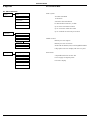
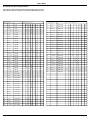
1
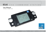
User Manual
mobile control
Version 1.0
December 2003
51100 mobile control user manual V1.01 12/2003
1
Content Table
1. Introduction ...................................................................................................................................................................... 3
2. Contents of package ......................................................................................................................................................... 3
3. Batteries ........................................................................................................................................................................... 3
4. Overview .......................................................................................................................................................................... 3
4.1. Features of mobile control ............................................................................................................................................. 3
4.2. Control elements of mobile control ................................................................................................................................ 4
4.3 LCD display ................................................................................................................................................................... 4
4.4. Control elements of the base station .............................................................................................................................. 5
5. Preparing operations ......................................................................................................................................................... 5
5.1. Connecting the base station ........................................................................................................................................... 5
5.1.1. X-Bus (Lenz, ROCO) .................................................................................................................................................... 5
5.1.2. I2C-Bus (Märklin, Uhlenbrock) ..................................................................................................................................... 6
5.2. Installing the batteries .................................................................................................................................................... 6
6. Your initial operating session ............................................................................................................................................. 6
6.1. Calling up another engine .............................................................................................................................................. 7
7. 1. Functions of mobile control .......................................................................................................................................... 7
7.1. Run engines ................................................................................................................................................................... 7
7.1.1. Lists ........................................................................................................................................................................... 7
7.1.2. Selecting engines ........................................................................................................................................................ 7
7.1.3. Properties of engines ................................................................................................................................................... 8
7.1.3.1. Changing the name of the engine ............................................................................................................................ 8
7.1.3.2. Protocol ................................................................................................................................................................... 8
7.1.3.3. Symbol .................................................................................................................................................................... 8
7.1.3.4. Vmax ...................................................................................................................................................................... 8
7.1.3.5. Speed step mode ..................................................................................................................................................... 9
7.1.3.6. Functions ................................................................................................................................................................ 9
7.1.3.7. Address ................................................................................................................................................................... 9
7.1.4. New engine ................................................................................................................................................................ 9
7.1.5. Delete engine ............................................................................................................................................................. 9
7.2. Switch accessories ....................................................................................................................................................... 10
7.2.1. New accessory .......................................................................................................................................................... 10
7.2.2. Switch accessory ....................................................................................................................................................... 10
7.2.3. Delete accessory ....................................................................................................................................................... 11
7.3. Other functions ............................................................................................................................................................ 11
7.3.1. Using access codes ................................................................................................................................................... 11
7.3.2. Using additional mobile controls with one base station .............................................................................................. 11
7.3.3. Using additional base stations ................................................................................................................................... 12
7.3.4. Data transfer between mobile parts ........................................................................................................................... 12
7.3.5. Copy engine and accessory data................................................................................................................................ 13
7.3.6. Setting the X-bus address .......................................................................................................................................... 13
7.3.7. Select language ......................................................................................................................................................... 13
7.3.8. Adjust contrast ......................................................................................................................................................... 13
8. Other operating modes ................................................................................................................................................... 13
8.1. 1.1 Connect base station to other Command Station .................................................................................................... 13
9. 1. Appendix .................................................................................................................................................................... 14
9.1. Menu structure ............................................................................................................................................................ 14
9.2. Technical data .............................................................................................................................................................. 14
9.3. Table with codes for accessory decoders ....................................................................................................................... 15
10. support & help.............................................................................................................................................................. 16
Märklin® is a registered trademark of the company Gebr. Märklin® und Cie. GmbH, Goeppingen, Germany.
Xpressnet is a registered trademark of the company Lenz Elektronik, Gießen, Germany.
Copyright 2003, 2004 by ESU electronic solutions Ulm GmbH & Co. KG. Electrical characteristics and dimensions are subject to change
without prior notice. ESU may not be held responsible for any damage or consequential loss or damage caused by inappropriate use of
the product, abnormal operating conditions, unauthorized modifications to the product, etc.
ESU electronic solutions Ulm GmbH & Co. KG reserves the right to make changes and improvements to any of the products described in
this document without prior notice.
The contents of this document are provided „as is.“. No warranties of any kind, either express or implied, including, but not limited to,
the implied warranties of merchantability and fitness for a particular purpose, are made in relation to the accuracy and reliability or
contents of this document.
ESU electronic solutions Ulm GmbH & Co. KG reserves the right to revise this document or withdraw it at any time without prior notice.
Not suitable for children under 3 years of age. Inappropriate use may result in injury due to sharp points and edges.
2
51100 mobile control user manual V1.01 12/2003
Introduction
1. Introduction
Congratulations to your purchase of mobile control by ESU electronic
solutions ulm GmbH & Co. KG. Mobile control provides you with
the opportunity to finally run your engines without cables. The
easy handling and the ergonomic design of the handheld controllers
offers you new ways of operating and more fun running your trains.
This manual provides step-by-step instructions on how to operate
mobile control. Therefor we have one request:
Please read and study this manual carefully before starting operations.
Even though mobile control is extremely robust, a wrong connection
could lead to failure and destruction of the unit.
2. Contents of Package
The package should contain the following components:
• 1 mobile control
• 1 base station
• 1 cable to connect to the X-bus (resp. XpressNet)
• 1 leaflet with pictures
• 1 warranty card
• this manual
3. Batteries
In order to operate mobile control you need batteries which are
not supplied with the system. You can either use alkaline batteries
or rechargeable batteries (NiCd or NiMH).
Important Remarks
Three batteries or re-chargeable batteries of the type „AAA“
(also known as „Micro“) are required.
Mobile control is solely designed for the use with model trains.
Never operate the unit without supervision and never use it
to control equipment transporting persons.
With one set of batteries mobile control can be operated between
5 and 25 hours (depending on the capacity of the used batteries).
We recommend the use of rechargeable NiMH batteries with at
least 250 mAh. They are usually available at any hardware store or
discount market.
Mobile control may only be used in conjunction with other
components listed in this manual. Any other use than
described in this manual is not permitted.
Connect the mobile control system only to equipment
described in this manual. Even though other equipment may
have the same type and size of sockets or connectors, it does
not indicate that such equipment will function with mobile
control.
Please note, that the base station does not contain a battery charger.
That means, that even when using rechargeable batteries you have
to remove them and recharge them with a separate charger. Such
battery chargers are usually available at hardware stores or discount
markets.
Mobile control operates within the 433 MHz ISM radio
frequency range, that is free of charge and does not require
registration. Since this frequency range is available to anybody,
there is a possibility of disturbance caused by other radio
transmitters such as automatic garage door openers,
computer mice without cables, audio headphones.
4. Overview
Do not drop or shake mobile control, nor expose it to
mechanical impact of any kind. Such inappropriate treatment
may cause component failure.
4.1. Features of mobile control
Do not expose any components of the mobile control system
to moisture or direct sunlight.
Do not use any aggressive chemicals, cleaning solutions or
acid cleaning agents for cleaning mobile control.
Do not attempt to open mobile control. Such inappropriate
treatment may cause damage to the unit.
51100 mobile control user manual V1.01 12/2003
With mobile control you have purchased a handheld controller
that offers far more than wireless control of your engines. In this
chapter we will introduce the many features of the mobile control
system.
Ergonomics
At first glance you will note that mobile control is not just „any“
handheld controller with the wires removed. It is a handheld designed
according to ergonomic requirements. It not only fits perfectly in
your hand, it is also the first handheld controller suitable for singlehand-operation. You control the speed with your thumb, your other
hand remains free! Due to the layout of the control buttons you
can „feel“ what you are doing without looking.
Another important design feature is to assure easy handling. Therefor
mobile control is equipped with a large, graphic LCD display that
provides information on the most important parameters at all times.
Address, engine symbol, engine name, speed (in km/h or speed
steps) as well as the status of functions. You can activate up to 10
(!) functions (plus light) directly by pushing a button.
3
Control Elements of mobile control
Mobile control can do much more: Besides running engines you
can also control accessories: Never was it easier to run your layout
more intuitively. At any time the display shows the current position
of a turnout, switching is done by simply pressing a button.
More fun running your trains
Mobile control stores much more information: Besides basic data
such as address, digital mode and number of speed steps stored
for each engine quite a bit of additional data is stored. Data, that
adds up to more fun with your hobby. You can enter an individual
name for each engine. Never again do you have to remember the
decoder address! You can also allocate a symbol for each engine
allowing you to recognise the type of engine at a glance. All
functions can be set individually for momentary action or continuous
output. This is ideal for controlling LokSound equipped engines.
The „icing on the cake“ in terms of handling comfort is the setting
of the maximum speed in km/h so you can monitor the „real“
speed rather than speed steps.
Radio Control
Besides all these features mobile control excels due to its wireless
operation: Without depending on wires all signals are transmitted
via radio waves to the base station. This bi-directional radio
transmission is reliable and fast, hence there is no delayed response.
The signal is strong enough to enable you to run your layout even
from a distance of 100 m from the base station (outside). Even
concrete walls in your basement are no problem.
Connection
While the handheld communicates with the base station, the latter
is to be connected to the bus for handheld controllers of your
digital system. It can be connected to any digital system using I2Cbus, particularly the Märklin control unit 6021, Uhlenbrock
Intellibox, or X-bus particularly the Lenz digital plus, Roco LokMaus
II. Mobile control then operates like any other handheld controller
connected by a cable. The base station co-ordinates the
communication between the digital system and mobile control.
You can connect up to 4 hand held controllers to each base station.
Configuration is automatic. In total there may be up to 4 base
stations within the transmission area (approximately 100 m radius).
The maximum configuration is thus 16 (!) mobile controls operating
at the same time within the above mentioned area.
4.2. Control Elements of mobile control
Mobile control has the following control elements (Fig. 1):
a) LCD Display: On the graphic LCD display all relevant information
will be shown subject to the respective operating mode.
b) Selection buttons: The current function of any such button is
indicated by the respective symbol in the LCD display located
just above the buttons.
c) Speed control wheel with „centre-click“: You can increase or
reduce the speed by turning this wheel. Applying pressure on
the speed control wheel activates change of direction. You can
select the desired topic within each menu by turning the wheel
and confirm your selection by pressing it.
d) Engine button: Push this button and a list of all registered engines
in a „Top-Ten-List“ will appear or it starts the running mode for
engines.
e) Accessory button: Pushing this button will display the last used
accessory, pushing it a 2nd time will list all registered accessories.
f) Key pad: the buttons from 0 – 9 are used to enter either numbers
or characters or to activate functions F1 to F10 of the engine
currently controlled.
button switches the headlights on or off. Whenever
g) The
mobile control expects a command, this button changes between
capital and lower case letters on the display.
h) The
button has several functions:
a. Turning on mobile control: push this button briefly (only
once) to switch on mobile control.
b. Turning off mobile control: If the unit is switched on, push
and hold this button for about 5 seconds, until mobile control
is turned off.
c. Emergency stop: When the unit is switched on, a short
push of the button activates the emergency stop.
d. Deactivate emergency stop: Push this button briefly to release
the emergency stop mode.
4.3 Information shown on the LCD-display:
In the basic mode the data of the currently controlled engine or
accessory is displayed.
Display of Engines (Fig. 2)
i) Name of engine (plain text): displays the name assigned to this
engine.
j) Symbol: displays the symbol assigned to this engine.
Comfort and safety
All mobile controls registered at one base station form a network:
each unit can transmit its data (e.g. lists of engines or accessories)
to any other unit. Thus you have to enter the data of any engine or
turnout only once, the other handheld controllers will automatically
receive this information.
k) Address: displays the decoder address with which the displayed
engine is controlled.
l) Protocol: displays the digital protocol currently in use (depending
on the command station to which your base station is
connected).
m) Current speed of engine: displays either the current speed steps
or speed in km/h (scaled to speed steps, see also chapter 7.1.3.4).
In order to protect mobile control from unauthorised use each
controller can have its own PIN number. You can also restrict
access of any new controller to your base station with another
PIN.
4
n) Current direction of travel.
o) Status of functions of engine currently controlled: A tiny square
represents each function button on the display (headlights, F1
to F10). The off-status is indicated by a dot while a bold point
indicates the on-status.
51100 mobile control user manual V1.01 12/2003
Control Elements of the Base Station
The squares are arranged in the same way as the key pad f) to
allow easy recognition of the squares and their corresponding
functions. Please note, the number of squares shown depends on
the digital system: The IIC-bus only enables and displays the lighting
function and F1 – F4. When using X-bus all functions (lighting and
F1 – F10) will be displayed (but can only be used due to the
functionality of the digital system e.g. the ROCO Lokmaus 2 system
does provide only 4 functions).
5. Preparing for Operation
Display of Accessories (Fig. 3):
Unfortunately some incompatible bus systems for handheld
controllers are available on the market. The base station supports
the most commonly used bus systems in Europe:
p) Name of accessory in plain text: the name given this particular
accessory.
q) Symbol: For each output a symbol indicating the type of accessory
(e.g. signal, point) as well as the current status.
r) Possible positions: displays the possible switching positions.
Signal Reception and Battery Indicator
s) As long as there is a radio connection between the handheld
unit and the base station the symbol of the antenna will be
displayed. If this symbol is blinking or disappears altogether,
there is no radio contact.
t) If the battery voltage is below a critical value, a battery symbol
will be displayed left of the antenna symbol. Depending on the
type and quality of the batteries they have to be changed soon.
Should the battery voltage drop even further, then mobile control
will turn itself off.
Before you can use mobile control a few things have to be done.
5.1. Connecting the Base Station
The base station has to be connected to the command station. As
mentioned previously, the base station behaves like a handheld
controller as far as the command station is concerned. The command
station does not „notice“ that mobile control is actually a wireless
system.
a) X-bus: This bus developed by Lenz is in the public domain and
is not only used by Lenz but also for the ROCO LokMaus II and
Atlas Commander. Sometimes the X-bus is called XpressNet.
b) I2C-bus: This is used by Märklin to expand the control unit 6021.
The Intellibox by Uhlenbrock also uses this system.
Please note, that the base station may only be operated on
one or the other of these systems. Simultaneous connection
to both systems is not permitted and would damage or
destroy the base station!
Please turn off your command station completely (remove
the mains plug) before connecting the base station.
4.4. Control Elements of the Base Station
5.1.1. X-Bus (Lenz, ROCO)
The base station has only very few control buttons or connections.
Fig. 4 shows what’s available:
Use the supplied cable to connect the base station to the X-bus.
Insert one end into the socket at the back of the base station (Fig.
5) and connect the other end to the bus of the command station.
a) X-bus sockets: One of the sockets is used to connect to a
command station using X-bus (e.g. ROCO LokMaus 2, Lenz
digital plus, Lenz compact). Either socket serves the same
purpose.
b) I2C-bus: To connect to a command station using the I2C-bus
(Märklin control unit 6021, Uhlenbrock Intellibox, Fleischmann
Twin Center) simply plug the base station to the command station.
c) Holder for mobile control: When not in use you can „park“ the
handheld controller in this holder.
If you prefer to use the screw terminals LMAB of the Lenz central
unit LZ100 or LV100, cut the cable in the middle and connect the
individual wires to the terminals of the LZ100. The exact
configuration of the pins is shown in Fig. 6.
Important
d) Status-LED: indicates the operating status of the base station:
a. LED is on (continuous): base station has successfully registered
with the command station, has reserved an available
transmission channel and is ready for operation.
b. LED is blinking slowly: base station has registered with the
command station and is searching for an available
transmission channel.
Never connect the base station to a Loconet terminal of an
Intellibox (Uhlenbrock) or Fleischmann Twin Center: Even
though these systems use the same type of sockets, the
electrical configuration is quite different: this would result in
the destruction of both the base station and the command
station.
c. LED is blinking fast: base station could not register with the
command station. There is either a wrong connection or
the units are incompatible.
Please take note of the following advice (chapter 5.1.2.)
regarding the connection of the base station to the Intellibox
/ Twin Center.
51100 mobile control user manual V1.01 12/2003
5
Your First Run
Mobile control was tested with
5.2. Installing Batteries
• ROCO LokMaus 2
Before you can use mobile control you need to install batteries.
Proceed as per Fig. 8
• Lenz LH100 and command station LZ101 (software V3.0)
1. Turn the controller upside down and apply slight pressure onto
the cover of the battery compartment (1)
• Lenz LH200
• Lenz compact (Set 03)
2. Slide the cover to the back (2)
• Atlas commander
Mobile control only operates with Lenz equipment Version 3. Older
versions have to be updated before you can use mobile control.
3. Insert the batteries (3): Make sure the polarity is correct: the
„+“ pole is always the smaller, projecting contact. Make sure
the batteries sit correctly in the compartment and that the sprung
contacts are not bent or twisted.
X-Bus Address
4. Close the battery compartment by pushing the cover forward
until it is arrested.
All devises connected to the X-bus have to have their individual
address in order to assure correct communication with the command
station.
6. Your First Run
The base station can handle 4 addresses: one for each possible
handheld controller.
Once you have connected the base station and inserted the batteries
you are ready to run your first train with mobile control.
The base station is set to addresses 2,3,4,5 at the factory. Should
you operate another X-bus device on any of these addresses, then
you have to change the X-bus addresses for the base station. How
to do this is described in chapter 7.3.5. „Setting the X-bus address“.
• First switch on your digital system and observe if the status LED
of the base station is lit continuously.
Please note, that in most command stations not all of the possible
31 X-bus addresses are activated in their factory settings: Most
command stations only respond to addresses 1-4. Thus you may
have to increase the number of addresses monitored by your
command station. How to do this, is explained in the manual of
your command station.
• While you see the message „searching net“ on the display, mobile
control is checking for available base stations. As soon as it has
found a base station, it logs onto it.
5.1.2. I2C-bus (Märklin, Uhlenbrock)
• If there is an engine with address „03“ on the layout, you can
control this engine immediately:
The I2C-bus is used whenever the base station is to be connected to
one of the following digital systems:
• Switch on mobile control by pressing the
button briefly.
• Then mobile control changes into the „run“ mode. Engine
>0003< is automatically called up.
• Uhlenbrock Intellibox
o Increase the speed by turning the speed control wheel upwards.
This wheel operates with a certain dynamic: the faster you
turn it, the more speed steps it will skip. If you turn the wheel
slowly - step by step, however, you can control your engine
precisely.
• Fleischmann Twin Center
o Turn the wheel downwards to reduce speed.
The base station is to be plugged onto the right hand side of the
above central units. Please note, that the base station has to be
connected directly to the central unit: Other controllers (e.g. control
80f) have to be connected after the base station. Fig. 7 shows how
to typically connect the devices.
o Pressing the speed control wheel triggers a change of direction.
The current direction of travel is indicated by an arrow on the
display.
• Märklin control unit 6021
Always remove the mains plug before connecting the base station
to the central unit.
The mobile control system can now only use the Motorola Features of the above mentioned command stations.
Important
Never connect the base station with the X-bus cable to a
Loconet socket of the Uhlenbrock Intellibox / Fleischmann
Twin Center: Although these devices have the same type of
electrical sockets the wiring of the individual pins is different:
This will result in damage or destruction of the base station.
6
o Now you can activate the functions and headlights for this
engine by pressing any of the buttons from „1“ to „0“
respectively „*“. The status of each function is indicated by a
small square in the display.
The number of functions available depends on the type of digital
system: If the base station is connected to a control unit 6021 or
an Intellibox, then functions F1 to F4 and headlights are available.
When operating with X-bus then the number of functions
depends directly on the command station. Mobile control will
display all ten functions at all times, but cannot overcome the
limitations of the command station: The ROCO LokMaus, for
instance, only supports 4 functions. Just be aware, that such
limitations are not caused by mobile control but by the command
station.
51100 mobile control user manual V1.01 12/2003
Running Engines
6.1. Calling up another Engine
For running engines there are 3 lists:
If you want to run another engine, please proceed as follows:
• „Top Ten“ List: this contains the 10 engines most recently operated
in descending order. The „Top Ten“ list enables you to quickly
find your most important engines.
• Press the „engine“ button
• The menu for selecting an engine appears on the display
(Fig. 9).
• My Engines“: This list contains all engines ever entered in
alphabetic order. Mobile control can administer up to 100 (!)
engines.
Fig. 9
• BStart typing the desired address. As soon as you have entered
the first digit, a window appears (Fig. 10).
Fig. 10
• „Received Engines“: This list contains all engines that were
received via radio transmission from other handheld controllers.
You can only access this list, if you operate at least two mobile
control units.
7.1.2. Selecting Engines
If you want to run an engine the selection always starts with the
„Engine“ button. When you press this button, the „Top Ten“ list
will be displayed (Fig. 10). Use the speed control wheel to highlight
and select the desired engine. Should the required engine not be
listed press the left selection button to open the My Engines“ list
(Fig. 11). Press the left selection button once more to open the
„Received Engines“ list, provided there are any engines in this list.
If not, the „Top Ten“ list will reappear. Pressing the speed control
wheel confirms your selection. If you want to cancel this procedure,
pressing the right selection button will take you back.
• Complete typing the address.
• FIf you made a typing error, you can delete the last digit by
pressing the left selection button. Please note, the left selection
button is marked with the „delete symbol“ during this process.
• Confirm the address by pressing the speed control wheel.
•Now mobile control will automatically call up this engine and
change over into the „Run Engine“ mode. The number of speed
steps is automatically set to the value provided by the command
station.
Running your engines with mobile control is that easy. Of course,
mobile control can do much more. The following chapter outlines
the basic functions.
7. Features and Functions of mobile control
7.1. Running Engines
7.1.1. Lists
Contrary to other handheld controllers mobile control does not
work with addresses. It offers the possibility to identify each engine
with self-explanatory names, basic symbols and additional symbols.
Mobile control „remembers“ all parameters of an engine that you
have either entered or called up once. This information is stored in
an internal permanent memory. Basically mobile control
administers all engines in lists from which you may comfortably
select the desired engine.
51100 mobile control user manual V1.01 12/2003
Fig. 11
As soon as you have selected an engine the relevant data will appear
on the display. However, if an engine is already controlled by another
handheld controller, the engine symbol will blink.
If you want to take over this engine you have to confirm it if you
are using the control unit 6021 (or Uhlenbrock Intellibox) by pressing
the speed control wheel. Once mobile control has taken over this
engine the engine symbol will stop blinking and you can run this
particular engine. This engine can now be operated until you call
up another engine.
When using X-bus the explicit confirmation is not required: it is
sufficient to send a new command to the engine in order to take
over this engine from another controller. However, this engine can
be taken over by another controller at any time.
7
Engine Properties
7.1.3. Engine Properties
A number of attributes such as name, protocol (including speed
step mode), address, engine symbol, function button mode,
maximum speed, are stored. It is very easy to change any of these
attributes.
• Call up the desired engine
• Press the left selection button. Now you are in the menu „Setting Engines“ (Fig. 12)
The new letters are entered with the buttons in the same way as on
a mobile phone. All buttons have multiple functions. Thus you can
enter numbers and letters. Simply press the desired button several
times within a certain time frame.
After a moment the cursor will reappear and you may enter further
characters.
• Use the „*“ button to change between capital letters and lower
case.
• Use the „1“ button to enter space or special symbols.
7.1.3.2. Protocol
Fig. 12
• Turn the speed control wheel until the desired option is
highlighted.
• Confirm your selection by pressing the wheel
• Change the property as desired
• Pressing the wheel again confirms your selection.
• Pressing the right selection button cancels the procedure and
takes you back to the level above within the menu.
With this function you can set the number of speed steps or the
data format. Please remember, that when operating with X-bus,
the options DCC14, DCC28 and DCC128 will be available, while
with the IIC-bus only Motorola 14 can be selected. Mobile control
will only accept a selection corresponding with the features
supported by the command station.
7.1.3.3. Symbol
You can select a symbol for each engine in order to differentiate
between different types (steam engine, diesel engine, etc.). Mobile control offers a range of choices.
7.1.3.4. Vmax
Mobile control supports two options for displaying the speed:
7.1.3.1. Changing Engine Names
Often mobile control will demand entry of text or a number. This
will always happen in the same way. How to handle this is explained
by the following example (name of engine).
Let’s assume you want to change the name of the engine with the
factory setting „Engine>0003>“ to „Ludmilla BR 232“. You have
already called up this engine and pressed the left selection button.
• Select „Name“ from the menu „Engine Settings“ and confirm
with „OK“
The following menu appears (Fig. 13)
• In the speed step mode the current speed step setting is
displayed. Depending on the max. number of speed steps this
ranges from 0 – 14, 0 – 28 or 0 – 128.
• In the Vmax mode mobile control calculates the speed in km/h,
which is shown on the display.
Mobile control can only show the correct speed, if you have entered the maximum speed in km/h for each engine. This is the
maximum speed of the prototype, not the model.
This value will be displayed whenever the engine runs at the highest
speed step. All intermediate values will be interpolated by mobile
control.
Please note, that the values entered have nothing to do with
the real speed of the model: This option allows you to influence
the display but not the actual speed of the model.
Fig. 13
Now you can delete the old name with the left selection button.
Press the button until all old letters have disappeared.
8
The maximum speed is set by programming the decoder with
the command station (in DCC mode) ; Märklin models are
usually adjusted by setting some micro switches within the
engine.
51100 mobile control user manual V1.01 12/2003
Engine Properties
7.1.3.5. Speed Step Mode
7.1.3.7. Address
All engines are set to speed step mode ex factory. The appropriate
speed step is displayed. Select this mode, if you have activated the
Vmax option for a specific engine, and want to return to the speed
step mode.
In case the address of an engine has changed (e.g. because you
reprogrammed the address or set the DIP-switches of a Märklin
decoder) you can adjust or enter a new address in this menu.
Please note that mobile control cannot reprogram decoder addresses.
In this menu you only enter the new address into the memory of
your mobile control.
7.1.3.6. Functions
Mobile control stores the mode (momentary action or continuous)
of each individual function of each engine (F1 to F10).
• Continuous means each function remains on until you press the
appropriate button once more.
• Momentary action means the function remains active until you
release the button.
How to change decoder addresses is explained in the manual of
the decoders respectively of your command station.
7.1.4. New Engine
You can enter the data of new engines in two ways.
All buttons for all engines are factory pre-set to „continuous“. This
is in accordance with the typical settings of the most common
digital command stations such as control unit 6021, Intellibox,
LokMaus II.
Depending on the function you want to activate with a particular
button it may be useful to change it to momentary action: An
automatic coupler, for instance, should only be activated as long
as you press the button.
To change the mode is quite easy (ref. Fig. 14): After calling up
„Functions“ a list of the buttons F1 to F10 will be displayed. Next
to each symbol the current mode is displayed: either continuous or
momentary action. To change the mode select the desired button
by turning the speed control wheel and then press the selection
button.
• Implicit: Press the engine selection button to enter the engine
selection menu. Instead of selecting an engine from a list by
turning the speed control wheel you can enter and confirm the
address directly. If this address did not exist previously, the new
number will be established and you can run this engine
immediately. The other properties of this engine such as name,
symbol etc. can be entered or adjusted via the menu „Engine
Properties“.
• Explicit: Press the right selection button while in the main menu
and select „Engine“ (Fig. 15)
Fig. 15
Fig. 14
Once you have changed all buttons as desired, leave this menu by
pressing the speed control wheel. You can cancel this procedure
by pressing the right selection button at any time.
When using an Intellibox / Twin Center it is possible that
commands triggered by momentary action buttons are
incorrectly transmitted to the command station. We
recommend pressing the momentary action buttons longer
than 0.3 seconds to assure correct transmission.
o
Select „New“ in this menu
o
Enter the desired address and confirm by pressing the speed
control wheel
o
Now you can run this engine.
7.1.5. Delete Engine
You can delete an engine in the same menu:
• Press the right selection button while in the „Run Engine“ mode
or „Switch Accessories“ mode to open the menu.
• There you choose „Engine....“.
• Select „Delete Engines“.
• Now the list „My Engines“ will appear. Select the engine you
want to delete and confirm by pressing the speed control wheel.
• Instead of the engine name the message „Delete?“ will be
displayed. Confirm your choice once more by pressing the speed
control wheel.
51100 mobile control user manual V1.01 12/2003
9
Accessory
Addresses in Motorola Mode
• The engine is deleted. Now you may select other engines to be
deleted.
• You can cancel this procedure by pressing the right selection
button at any time.
7.2. Switch Accessories
With mobile control you can also switch points. The procedure is
similar to the one for handling engines. Below we will focus on the
differences between running engines and switching accessories.
Mobile control stores separate lists for accessories. There are only
two types of lists for accessories:
Mobile control sends commands to accessories with addresses
ranging from 1 to 256. These addresses must not be confused
with the Märklin terminology of keyboards and their buttons.
The following applies:
• Each Märklin keyboard can switch 16 accessories.
• There is a table in the appendix showing which keyboard
refers to which accessory address under „Codes for Accessory
Addresses“.
It is very easy to establish a new accessory:
• „My Accessories“: a complete list of all accessories
• „Received Accessories“: all accessories received from another
mobile control unit.
Push the right selection button in the main menu to open the
appropriate menu. Choose „Accessory...“ (Fig. 16)
First you have to change into the accessory mode. If there is an
accessory that has been called up already, it will be displayed. If no
accessory has been established yet mobile control will ask you to
enter data for an accessory.
7.2.1. New Accessory
Mobile control automatically administers the following attributes
for all accessories:
• Type of accessory: mobile control „recognises“ different,
frequently used accessories:
Fig. 16
• Select „New“
o
Point left
o
Point right
o
Crossing (diamonds)
o
Signal
• Now you decide if you want momentary action or continuous
output.
o
4 squares (general)
• Enter the desired name for the accessory.
When using the appropriate symbol mobile control will display the
current status (position). Thus you have an immediate overview
regarding the status of the accessory.
• Name: You can enter a name in plain language for each
accessory.
• Momentary action or continuous: Depending on the type of
drive you may wish to change from momentary action to
continuous output. Momentary action means the solenoids of
the accessory will only receive current as long as you press the
respective button. This is the correct way of switching solenoids,
however, for signals with LEDs or other lighting applications
„Continuous Output“ is better suited.
• The display will show the first possible type of accessory. Scroll
down by turning the speed control wheel until you see the desired
symbol and confirm by pressing the wheel once more.
• Enter the desired address.
• Mobile control will now change into the „Switch Accessories“
mode. By pressing the speed control wheel you can switch the
accessory.
7.2.2. Switch Accessories
This is very easy. On the display (see also Fig. 3) you see the
symbol of the respective accessory at the top left as well as the
current status (position) (e.g. straight or diverging). If this information
is not available from the command station nothing will be displayed.
• Address: the address of the accessory.
On the right the possible positions are displayed. You can select
the desired position with the speed control wheel and confirm by
pressing it once more. As soon as the position has changed, it will
be displayed correctly again.
10
51100 mobile control user manual V1.01 12/2003
Accessory
7.2.3. Delete Accessories
Deleting accessories works similar to deleting engines:
• Press the right selection button while in the engine or accessory
mode in order to open the appropriate menu.
Both, the PIN code for mobile control and for the base station
are set to 0000 ex factory.
• There you select „Accessory...“.
• Once you have entered the old code correctly you will be asked
to enter the new PIN.
• Select „Delete Accessory“.
• Enter a 4-digit number.
• The list „My Accessories“ appears. Select the accessory you want
to delete and confirm by pressing the speed control wheel.
• For safety reasons you will be asked to re-enter the new code.
Enter it again.
•Instead of the name of the accessory the message „Delete?“ will
appear. Please confirm your selection once more by pressing
the speed control wheel.
• If you made no typing error or cancelled the procedure by
pressing the right selection button, the new PIN code will be
activated.
• The accessory is now deleted and you may proceed by selecting
others for deletion.
• You may cancel this procedure by pressing the right selection
button at any time
When you next switch on mobile control you will be asked to enter
the PIN. You will have to enter the PIN for the base station as well,
provided you activated it.
7.3. Advanced Features
Important
Besides the basic features explained so far mobile control offers
more features, particularly for the advanced modeller.
7.3.1. Using Access Codes
Please make sure you remember your PIN codes: Should you
ever forget the PIN code, you cannot use your unit anymore.
The unit can only be re-activated after a complex reset
procedure. This service can only be carried out at the ESU
factory and will be charged for. It also means you have lost
any data of your engines and accessories.
You can protect mobile control with access codes (PIN) against
unauthorised use.
PIN codes are always 4-digit numbers.
Both, the base station and the handheld controller, may have their
own PIN, each serving a somewhat different purpose:
If you wish to de-activate your PIN code, simply change back to
„0000“.
7.3.2. Several mobile control with the same Base Station
• Mobile PIN: the access code for the handheld controller serves
mainly as protection against theft. If the PIN is activated, nobody
can do anything with this mobile control unit.
Each base station can operate up to 4 mobile controls. Administration is automatically done by the base station.
• Base PIN: this access code prevents other mobile control units
from logging onto your base station. Let’s assume you are
displaying a layout at a fair and you use mobile control. Without
the base PIN anybody could bring their own mobile control, log
onto your base station and start running your trains!
Please consider the following:
These PIN codes are entered in a particular menu:
• Press the right selection button while in the engine menu or
accessory menu.
• The more mobile controls operate with one base station, the
slower data transmission will become, since all mobile controls
share one radio channel.
• When operating with X-bus the base station must request an
individual X-bus address for each mobile control at the command
station. The desired X-bus address has to be entered directly on
the mobile control unit. Please also refer to the following chapter.
•Select „Settings“.
• Select „Base PIN“ respectively „Mobile PIN“.
• First enter the old PIN-number.
51100 mobile control user manual V1.01 12/2003
11
Additional functions
7.3.3. Using several Base Stations at the same time
This sequence is always as follows:
• First you have to decide which data should be transferred.
The system has been designed to permit operation of up to 4 base
stations within the transmission radius. Since each base station can
handle 4 mobile controls, a maximum of 16 (!) mobile controls
can be operated with one digital system.
• Then the transmitter must start the data transfer.
• The required receiver must be set to receiving mode.
• After completion of this process the files received will be found
in the list „Received Engines“ respectively „Received Accessories“.
More than one base station may be useful for the following reasons:
• Large layout: You want to operate more than 4 mobile controls
with your command station. Then you need to add another
base station.
• There are several layouts in the same room: If there are several
digital layouts within the same room e.g. at fairs or in club
rooms, each mobile control for a certain layout has to be
connected to the base station of that particular layout.
Please consider the following:
• A data transfer is only possible between mobile controls logged
onto the same base station.
• There may only be one transmitter and one receiving unit at
anyone time.
As stated before, both engine data and accessory data can be
transferred. Here is an example of how to transfer engine data.
As soon as several base stations are located within the area of
transmission, operating procedures change as follows:
As soon as one mobile control is switched on, it will start searching
for base stations. If it finds more than one base station you as the
user have to decide to which base station you want to log on.
Each mobile control can only be assigned to one base at any given
time.
Mobile control will display all base stations within reach. As shown
in Fig. 17 each base station has an 8-digit, alphanumeric code,
displayed in the following format: XX:XX:XX:XX.
a) Transmitting unit
• Press the right selection button while in the engine or accessory
mode.
• Select „Engine...“.
• Select „Transmit Data“.
• Now a list of all engines appears. If you only want to send the
data of one engine, then you select this particular engine and
confirm by pressing the speed control wheel. If you want to
send the data of all engines, then you press the left selection
button.
• Then mobile control will change into the transmission mode
(ref. to Fig. 18) and will wait until the receiving unit has received
the data. To achieve this the receiver(s) have to be activated:
Fig. 17
At the bottom of each base station is a label with this 8-digit
ID-code.
Fig. 18
b) Receiving unit
Select the desired base station by scrolling up or down and confirm
your choice by clicking the speed control wheel. Subsequently
mobile control will try to establish connection with this base station.
• Press the right selection button while in the engine or accessory
mode.
• Select „Engine...“.
• Select „Receive Data“.
7.3.4. Data Transfer between mobile controls
If more than one mobile control is operated with one base station
the controllers will exchange both engine and accessory data. Thus
all lists of engines and accessories can easily be copied.
12
• Then mobile control will change into the receiving mode (ref.
To Fig. 19) and will wait until data transfer has been completed.
After a successful transmission the data will be in the list „Received
Engines“.
Sending / receiving of accessories is done in the same manner,
except you start with the accessory menu
51100 mobile control user manual V1.01 12/2003
Additional functions
• Dutch
The factory setting is German and can easily be changed:
• Press the right selection button while in the engine menu or the
accessory menu.
• Select „Settings...“.
Fig. 19
• Select the option „Language“.
• Select the desired language from the list.
7.3.5. Copy Engine or Accessory Data
As outlined in the previous chapter received data will initially be
stored in the list „Received Engines „ respectively „ Received
Accessories“. You may want to copy such data into the list „My
Engines“ or „My Accessories“.
This is accomplished by the command „Copy Data“ in the engine
menu or accessory menu.
7.3.8. Adjust Contrast
You may adjust the contrast of the LCD-display as desired. This is
done in the menu „Settings“:
• Press the right selection button while in the engine menu or
accessory menu.
• Select „Settings....“.
After having selected this option a list of the received items appears.
You can copy the marked items by pressing the speed control wheel.
7.3.6. Setting the X-bus Address
• Select the option „Contrast“.
• A screen appears on which you can adjust the contrast by turning
the speed control wheel. Pressing the wheel confirms your
setting.
The contrast depends largely on the visual conditions but also on
the temperature.
Each mobile control requires a separate X-bus address when operated
with an X-bus capable command station. Each base station can
support 4 individual X-bus addresses. The X-bus address must be
set on the mobile control (and not on the base station).
8. Other Operating Modes
• Press the right selection button while in the engine or accessory
menu.
8.1. Base Station connected to a different Command
Station
• Select „Settings...“.
•Select „X-bus Address“.
• The current X-bus address will appear. Delete it with the left
selection button and enter the desired new X-bus address.
The permitted X-bus addresses range from 1 to 31. Please
refer to the manual of your command station to determine
which X-bus addresses are available.
7.3.7. Select Language
If you want to operate mobile control with a different base station
you have to consider the following:
Mobile control stores the data protocol for each engine or accessory.
The capability of the command station must correspond to the
settings of mobile control. If you disconnect a base station from a
control unit 6021 and reconnect it to an X-bus command station,
then the engines will not be ready to run: You have previously
selected the „Motorola“ format while the X-bus command station
can only deliver DCC.
Mobile control will alert you to this inconsistency by the blinking
display of the protocol. To fix this you need to change the protocol
settings as described in chapter 7.1.3.2.
Mobile control „understands“ 6 languages:
• German
• English
• French
• Italian
• Swedish
51100 mobile control user manual V1.01 12/2003
13
Technical Data
9. Appendix
9.2. Technical Data
9.1. Menu Structure
Engine
New
Radio system:
433 MHz ISM Band
Delete
10 channels
Copy Data
automatic channel selection
Send Data
bi-directional transmission, 76 kBit
Receive Data
up to 100 m transmission radius
up to 4 receivers within the radius
up to 4 mobile control units per receiver
Accessory
New
Delete
Copy Data
Mobile control:
Memory for 100 engines
Send Data
Memory for 100 accessories
Receive Data
Works with 3 batteries (AAA) or rechargeable batteries
Full graphic FSTN LCD Display with 96 x 55 pixel
Settings
Language
X-Bus Address
Mobile Pin
Base station:
compatible with X-bus and IIC-bus
Power supply via digital system
LED status display
Base Pin
Contrast
14
51100 mobile control user manual V1.01 12/2003
Code Table
9.3. Codes for Accessory Decoders
This table contains the relationship between the position of the
DIP-switches and the address, as well as the Märklin keyboards.
Keyboard
Number
Keyboard
button
Accessory Address
Switch Decoder
DIP-switch in ON position
1
1
1
1
2
2
2
2
3
3
3
3
4
4
4
4
5
5
5
5
6
6
6
6
7
7
7
7
8
8
8
8
9
9
9
9
10
10
10
10
1..4
5..8
9..12
13..16
1..4
5..8
9..12
13..16
1..4
5..8
9..12
13..16
1..4
5..8
9..12
13..16
1..4
5..8
9..12
13..16
1..4
5..8
9..12
13..16
1..4
5..8
9..12
13..16
1..4
5..8
9..12
13..16
1..4
5..8
9..12
13..16
1..4
5..8
9..12
13..16
1-4
5-8
9-12
13-16
17-20
21-24
25-28
29-32
33-36
37-40
41-44
45-48
49-52
53-56
57-60
61-64
65-68
69-72
73-76
77-80
81-84
85-88
89-92
93-96
97-100
101-104
105-108
109-112
113-116
117-120
121-124
125-128
129-132
133-136
137-140
141-144
145-148
149-152
153-156
157-160
1
1
1
1
1
1
1
1
1
1
1
1
1
-
2
2
2
2
2
2
2
2
2
2
2
2
2
2
3
3
3
3
3
3
3
3
3
3
3
3
3
3
-
51100 mobile control user manual V1.01 12/2003
4
4
4
4
4
4
4
4
4
4
4
4
4
4
5
5
5
5
5
5
5
5
5
5
5
5
5
5
5
5
5
-
6
6
6
6
6
6
6
6
6
6
6
6
6
6
7
7
7
7
7
7
7
7
7
7
7
7
7
7
7
7
7
7
7
7
7
7
7
7
7
7
-
8
8
8
8
8
8
8
8
8
8
8
8
8
8
Keyboard
Number
Keyboard
button
Accessory Address
Switch Decoder
DIP-switch in ON position
11
11
11
11
12
12
12
12
13
13
13
13
14
14
14
14
15
15
15
15
16
16
16
16
1..4
5..8
9..12
13..16
1..4
5..8
9..12
13..16
1..4
5..8
9..12
13..16
1..4
5..8
9..12
13..16
1..4
5..8
9..12
13..16
1..4
5..8
9..12
13..16
161-164
165-168
169-172
173-176
177-180
181-184
185-188
189-192
193-196
197-200
201-204
205-208
209-212
213-216
217-220
221-224
225-228
229-232
233-236
237-240
241-244
245-248
249-252
253-256
1
1
1
1
1
1
1
1
-
2
2
2
2
2
2
2
2
3
3
3
3
3
3
3
3
4
4
4
4
4
4
4
-
5
5
5
5
5
5
5
5
5
-
6
6
6
6
6
6
-
8
8
8
8
8
8
8
8
8
8
8
8
8
-
15
Support & Assistance
10. Service-Support and assistance
Your model train or hobby shop is your competent partner for all
your questions regarding mobile control.
You may also contact us directly. For enquiries please use either
email or fax (don't forget to provide your own fax-no.) and we
will reply within a few days.
Please call our hotline only in case of complex enquiries that
can't be dealt with by email or fax. The hotline is often very
busy you may encounter delays. Also check our website for
more information. You will find many hints regarding FAQ
and even feed back from other users.
by phone: ++49 (0)731 – 18478-0
Tue from 10 am to 12 am
We from 10 am to 12 am
by Fax :
++49 (0)731 - 18478-299
by email:
[email protected]
by mail:
ESU electronic solutions ulm GmbH & Co KG
- technischer Support Industriestraße 5
D - 89081 Ulm
Internet:
www.loksound.de
printed in Germany
16
51100 mobile control user manual V1.01 12/2003