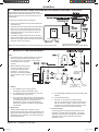
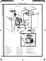
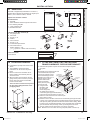
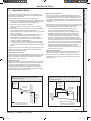
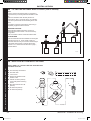
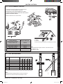
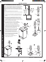
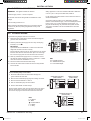
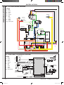
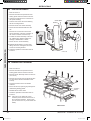
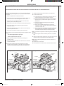
1
INSTALLATION AND SERVICING MEXICO HE15, HE18, HE24, HE30, HE36 For details of document amendments, refer to page 3 When replacing any part on this appliance, use only spare parts that you can be assured conform to the safety and performance specification that we require. Do not use reconditioned or copy parts that have not been clearly authorised by Ideal. For the very latest copy of literature for specification and maintenance practices visit our website www.idealheating.com where you can download the relevant information in PDF format. March 2013 UIN 201787 A09 201787-9.indd 1 25/03/2013 13:53:14 2 201787-9.indd 2 mexico HE - Installation & Servicing 25/03/2013 13:53:14 Notes for the installer For any technical queries plese ring the ideal installer/technical helpline : 01482 498663 DOCUMENT amendments Relevant Installation changes implemented in this book from Mod Level.........A08 (Mar 12) to A09 (Mar 13) Page 25, Frame 32 - Flue Arrangement Update to UIN’s on Weather Collar Page 50, Short Parts List Delete Parts list Ideal Heating reserve the right to vary specification without notice mexico HE - Installation & Servicing 201787-9.indd 3 3 25/03/2013 13:53:14 GENERAL Table 1 - General Data Boiler Size HE15HE18HE24HE30HE36 Gas Supply Connection Rc 1/2 in. BSP Flow and Return Connections Rc 1/2 22mm copper 22mm copper Rc 1/2 Rc 1/2 Rc 1/2 22mm copper 22mm copper 22mm copper maximum Static Water Head m (ft.) 30.5 (100) 30.5 (100) 30.5 (100) 30.5 (100) 30.5 (100) MINIMUM Static Water Head m (ft.) 0.45 (1.5) 0.45 (1.5) 0.45 (1.5) 0.45 (1.5) 0.45 (1.5) Electrical Supply 230V - 50Hz 230V - 50Hz 230V - 50Hz 230V - 50Hz 230V - 50Hz Power Consumption 38W 38W 38W 42W 42W Fuse RatingExternal : 3A internal T3.15A L250V Water Content litre (gal.) 2.0 (0.44) 2.0 (0.44) 2.0 (0.44) 4.7 (1.0) 4.7 (1.0) Packaged Weight kg. (lb.) 55.4 (122.4) 55.4 (122.4) 55.4 (122.4) 69 (152) 69 (152) Maximum Inst Weight kg. (lb.) 52 (114.6) 52 (114.6) 52 (114.6) 68 (150) 68 (150) Boiler Size Height mm (in.) 850 (33.5) 850 (33.5) 850 (33.5) 850 (33.5) 850 (33.5) Width mm (in.) 450 (17.7) 450 (17.7) 450 (17.7) 450 (17.7) 450 (17.7) Depth mm (in.) 530 (20.9) 530 (20.9) 530 (20.9) 530 (20.9) 530 (20.9) Gas Type I2H-G20 I2H-G20 I2H-G20 I2H-G20 I2H-G20 Gas Supply Pressure 20mb 20mb 20mb 20mb 20mb 100 (4) 100 (4) 100 (4) 100 (4) 100 (4) 6 6 6 3 3 Flue duct diameter mm (in.) Flue horizontal duct length (max) m Table 2 - Performance Data Boiler Size HE15HE18HE24HE30HE36HE15-24HE30-36 max maxmaxmaxmax min min Input ‘Q’ Nett CV Gross CV kW (Btu/h) kW (Btu/h) Gas Consumption l/s (cu.ft/h) 15.1 (51,500) 18.7 (63,800) 24.4 (83,300) 30.7 (104,700) 37.5 (128,000) 9.1 (31,000) 10.6 (36,200) 16.8 (57,200) 20.7 (70,800) 27.1 (92,500) 34.0 (116,000) 41.6 (142,000) 10.1 (34,400) 11.8 (40,300) 0.43 (54.7) 0.53 (68.0) Output ‘P’ 70oc Mean Water temp. kW (Btu/h)14.6 (50,000) 18.2 (62,300) 40oc Mean Water temp. kW (Btu/h)15.5 (53,000) 19.2 (65,700) Seasonal efficiency (SEDBUK) * Band A [90.4]% 0.70 (89.7) 0.26 (33.3) 0.30 (38.4) 23.4 (80,000) 30.1 (102,700) 37.0 (126,200) 8.8 (30,000) 10.6 (36,200) 25.1 (85,700) 32.8 (111,800) 39.8 (135,800) 9.6 (32,800) 11.4 (38,900) - - [90.3]% [90.2]% NOx classification * 0.88 (111.9) [90.4]% 1.07 (136.0) [90.7]% Class 5 The value is used in the UK Government’s Standard Assessment Procedure (SAP) for energy rating of dwellings. The test data from which it has been calculated have been certified by a notified body. Key to symbols Note. Gas consumption is calculated using a calorific value of 38.7 MJ/m3 (1038 Btu/ft3) gross or 34.9 MJ/m3 (935 Btu/ft3) nett. To obtain the gas consumption at a different calorific value:- GB = United KingdomIE = Ireland (Countries of destination) PMS=Maximum operating pressure of water C13 c33 = A room sealed appliance designed for connection via ducts to a horizontal or vertical terminal which admits fresh air to the burner and discharges the products of combustion to the outside through orifices which, in this case, are concentric. The fan is up stream of the combustion chamber. I2H An appliance designed for use on 2nd Family gas, Group H only. a. For l/s- divide the gross heat input (kW) by the gross C.V. of the gas (MJ/m3) b. For ft3/h - divide the gross heat input (Btu/h) by the gross C.V. of the gas (Btu/ft3) c. For m /h - multiply l/s by 3.6 3 = Caution. To avoid the possibility of injury during the installation, servicing or cleaning of this appliance, care should be taken when handling edges of sheet steel components. 4 201787-9.indd 4 mexico HE - Installation & Servicing 25/03/2013 13:53:15 mexico HE General Natural Gas only Boiler sizeG.C. Appliance No.PI No. (Benchmark No.) HE15 41-429-39 0063 BQ 3906 HE18 41-429-65 0063 BQ 3906 HE24 41-429-98 0063 BQ 3906 HE30 41-429-99 0063 BQ 3906 HE36 41-415-20 0063 BQ 3906 Destination Countries: GB, IE Contents Air Supply ....................................................................... 9 Benchmark Commissioning Checklist ...................... 54 Boiler Clearances .......................................................... 6 Boiler Exploded Diagram ............................................ 14 Electrical Connections ................................................ 27 Electrical Supply ........................................................... 9 Electrical Systems Diagrams ..................................... 29 Extension Ducts - Fitting ............................................ 22 Fault Finding ........................................................... 45-49 Flow Wiring Diagram ................................................... 28 Flue Fitting .............................................................. 19-26 Flue Installation Requirements .................................... 8 Gas Safety Regulations ................................................ 7 Gas Supply ..................................................................... 8 Initial Lighting .............................................................. 30 Installation ............................................................... 14-31 Mandatory Requirements ............................................. 7 Safe Handling ................................................................. 7 Servicing ................................................................. 32-44 Short List of Parts ....................................................... 50 Terminal Guards ............................................................ 8 Thermostatic Radiator valves ..................................... 9 Water and Systems ............................................... 10-13 Water Connections ................................................... 6,17 Water Treatment ......................................................... 13 Wiring Diagrams ..................................................... 27-29 For GB, to comply with Building Regulations Part L1 (Part 6 in Scotland) the boiler should be fitted in accordance with the manufacturer’s instructions. Self-certification that the boiler has been installed to comply with Building Regulations can be demonstrated by completing and signing the Benchmark Commissioning Checklist. Before installing this boiler, read the Code of Practice sheet at the rear of this book. Benchmark Commissioning Checklist Details Boiler Page Make and model.......................................................... 5 Appliance serial no. on data badge .......................... 14 SEDBUK No. %........................................................... 4 Controls Time and temperature control to heating.................. 29 Time and temperature control to hot water .............. 29 Heating zone valves................................................. n/a TRV’s.......................................................................... 9 Auto bypass................................................................ 9 Boiler interlock............................................................. 9 For ..................................................................... all boilers Flushing to BS.7593.................................................. 13 Inhibitor..................................................................... 13 Central heating mode Heat input....................................................to be calculated Page Burner operating pressure............measure and record Central heating flow temp.............measure and record Central heating return temp..........measure and record For combination boilers only Scale reducer........................................................... n/a Hot water mode Heat input................................................................. n/a Max. operating burner pressure............................... n/a Max. operating water pressure................................. n/a Cold water inlet temp............................................... n/a Hot water outlet temp............................................... n/a Water flow rate at max. setting................................. n/a For condensing boilers only Condensate drain...................................................... 17 For all boilers: complete, sign & hand over to customer For assistance see Technical Helpline on the back page NOTE TO THE INSTALLER: COMPLETE THE BENCHMARK COMMISSIONING CHECKLIST AND LEAVE THESE INSTRUCTIONS WITH APPLIANCE mexico HE - Installation & Servicing 201787-9.indd 5 5 25/03/2013 13:53:15 GENERAL 1 BOILER SERVICE CONNECTIONS 450 (173/4) 530 (21) 225 (87/8) 1. This appliance is NOT suitable for use in a direct hot water system. 2. If the boiler is to be used on a sealed system an Overheat Thermostat is fitted as standard. 850 (331/2) 232 (91/8) 288 (115/16) 348 (1311/16) Flow Return Gas Flow Return Gas Flammable materials must not be placed in close proximity to the appliance. Materials giving off flammable vapours must not be stored in the same room as the appliance. Floor mounting 1. The floor must be flat, level and of suitable load bearing capacity. 2. The back of the boiler may be fitted up to the wall. Boiler In addition a MINIMUM clearance of 450 mm (17 /4”) must be available at the front of the boiler, for servicing. FlueOverall Space Dim. Model LengthDepthHeight Width HE15 6m HE18 6m 530 870460 HE24 6m 530 870460 HE30 3m 530 870460 HE36 3m 530 870460 The minimum overall dimensions of the space in which the boiler is to operate and to facilitate servicing are as shown 3 mxhe7564 530 870460 Top clearance Boiler clearances Additional space may be required for installation, depending upon site conditions. 449 (171/16) 467 (183/8) All dimensions in mm (in.) 2floor mounting and BOILER CLEARANCES 690 (271/4) 20 (3/4) 5 (1/4) 5 (1/4) mxhe7565 Minimum front clearance when built behind a concealing panel is 5mm (1/4”). All dimensions in mm (in.) INTRODUCTION The mexico HE range of boilers are fully automatically controlled, floor standing, low water content, balanced flue, fanned, condensing gas boilers. They have full modulating central heating outputs of : HE15 8.8 kW (30,000 Btu/h) to 14.6 kW (50,000 Btu/h). HE18 8.8 kW (30,000 Btu/h) to 18.2 kW (62,300 Btu/h). HE24 8.8 kW (30,000 Btu/h) to 23.4 kW (80,000 Btu/h). HE30 10.6 kW (36,200 Btu/h) to 30.1 kW (102,700 Btu/h). HE36 10.6 kW (36,200 Btu/h) to 37.0 kW (126,200 Btu/h). Due to the very high efficiency of the boiler a plume of water vapour will form at the flue terminal during operation depending on external conditions. 6 201787-9.indd 6 The boiler casing is of white painted mild steel with the user controls capable of being mounted remotely from the boiler, if the option is required. The heat exchanger is of cast aluminium. Artificially softened water must NOT be used. A pre-piping frame is provided to allow system and gas connection to be made prior to boiler installation. Note. These boilers cannot be used on systems which include gravity circulation. The boilers are suitable for connection to fully pumped, open vented or sealed water systems. Adequate arrangements for completely draining the system by provision of drain cocks MUST be provided in the installation pipework. mexico HE - Installation & Servicing 25/03/2013 13:53:16 General Operation OTHER OPTIONAL KITS: When there is a demand for heat, the heating system is supplied at the selected temperature of between 30oC and 82oC. The boiler features a comprehensive diagnostic system which gives detailed information on the boiler status when operating, and performance of key components to aid commissioning and fault finding. Safe Handling This boiler may require 2 or more operatives to move it to its installation site, remove it from its packaging base and during movement into its installation location. Manoeuvring the boiler may include the use of a sack truck and involve lifting, pushing and pulling. Caution should be exercised during these operations. Operatives should be knowledgeable in handling techniques when performing these tasks and the following precautions should be considered: • Grip the boiler at the base. • Be physically capable. • Use PPE as appropriate, e.g. gloves, safety footwear. During all manoeuvres and handling actions, every attempt should be made to ensure the following unless unavoidable and/or the weight is light. • Keep back straight. • Avoid twisting at the waist. • Avoid upper body/top heavy bending. • Always grip with the palm of the hand. • Use designated hand holds. • Keep load as close to the body as possible. • Always use assistance if required. Adjustable Flue Support Bracket Safety Current Gas Safety (Installation and Use) Regulations or rules in force. The appliance is suitable only for installation in GB and IE and should be installed in accordance with the rules in force. In GB, the installation must be carried out by a Gas Safe Registered Engineer. It must be carried out in accordance with the relevant requirements of the: • Gas Safety (Installation and Use) Regulations • The appropriate Building Regulations either The Building Regulations, The Building Regulations (Scotland), Building Regulations (northern Ireland). • The Water Fittings Regulations or Water bye-laws in Scotland. • The Current I.E.E. Wiring Regulations. Where no specific instructions are given, reference should be made to the relevant British Standard Code of Practice. In IE, the installation must be carried out by a Registered Gas Installer and installed in accordance with the current edition of I.S.813 “Domestic Gas Installations”, the current Building Regulations and reference should be made to the current ETCI rules for electrical installation. Detailed recommendations are contained in the following British Standard Codes of Practice: BS. 5440:1 Flues (for gas appliances of rated input not exceeding 70 kW). Optional extra kits FLUING: Flue Extension Ducts. HE15, 18 & 24 -up to 6m HE30, & 36 - up to 3m Remote User Control Kit Condensate Pump Kit Concealment Panel Kit RS Boiler Terminal Wall Plate Kit (1000mm long) BS. 5440:2 Ventilation (for gas appliances of rated input not exceeding 70 kW). BS. 5449 Forced circulation hot water systems. BS. 5546 Installation of gas hot water supplies for domestic purposes (2nd Family Gases). BS. 6798 45o Elbow Kit (60/100 dia maximum no. per installation) HE15, 18 & 24 -up to 4 elbows HE30, & 36 - up to 2 elbows Installation of gas fired hot water boilers of rated input not exceeding 60 kW. BS. 6891 Low pressure installation pipes. Concentric Flue Screw Retaining Kit The Electricity at Work Regulations, 1989. 90o Elbow Kit (60/100 dia maximum no. per installation) HE15, 18 & 24 -up to 4 elbows HE30, & 36 - up to 2 elbows Roof Flue Kit (60/100) HE15, 18 & 24 -up to a maximum of 8m HE30, & 36 -up to a maximum of 5m Pitched Roof Tile (for roof flue kit) Flat Roof Tile (for roof flue kit) Vertical Flue Adaptor Vertical Outlet Flue Kit with Elbow (60/100) HE15, 18 & 24 - to a maximum length of 6m HE30, & 36 - to a maximum length of 3m Flue Finishing Kit High Level Flue Outlet Kit Flue Deflector Kit Health & Safety Document No. 635 The manufacturer’s notes must NOT be taken, in any way, as overriding statutory obligations. IMPORTANT. These appliances are CE certificated for safety and performance. It is, therefore, important that no external control devices, e.g. flue dampers, economisers etc., are directly connected to these appliances unless covered by these Installation and Servicing Instructions or as otherwise recommended by Ideal Heating in writing. If in doubt please enquire. Any direct connection of a control device not approved by Ideal Heating may invalidate the certification and the normal appliance warranty. It could also infringe the Gas Safety Regulations and the above regulations. Safe handling of substances mexico HE - Installation & Servicing 201787-9.indd 7 Care should be taken when handling the boiler insulation panels, which can cause irritation to the skin. No asbestos, mercury or CFCs are included in any part of the boiler or its manufacture. 7 25/03/2013 13:53:17 GENERAL Location of boiler The boiler must be installed on a flat and level floor, capable of adequately supporting the weight of the boiler and any ancillary equipment. The boiler may be fitted on a combustible floor. Insulation is not necessary, unless required by the local authority. For electrical safety reasons there must be no access from the back of the boiler. The boiler must not be fitted outside. Timber Framed Buildings If the boiler is to be fitted in a timber framed building it should be fitted in accordance with the Institute of Gas Engineering document IGE/UP/7:1998. Bathroom Installations The boiler MUST be installed on a gas supply with a governed meter only. A gas meter can only be connected by the local gas supplier or by a Gas Safe Registered Engineer. In IE by a Registered Gas Installer (RGII). An existing meter should be checked, preferably by the gas supplier, to ensure that the meter is adequate to deal with the rate of gas supply required. This appliance is rated IP20. It is the responsibility of the Gas Installer to size the gas installation pipework in accordance with BS6891:2005. Whilst the principle of the 1:1 gas valve ensures the Logic + range is able to deliver it’s full output at inlet pressures as low as 14mb, other gas appliances in the property may not be as tolerant. When operating pressures are found to be below the minimum meter outlet of 19mb these should be checked to ensure this is adequate for correct and safe operation. The boiler may be installed in any room or internal space, although particular attention is drawn to the requirements of the current IEE (BS.7671) Wiring Regulations and the electrical provisions of the building regulations applicable in Scotland, with respect to the installation of the boiler in a room or internal space containing a bath or shower. For IE reference should be made to the current ETCI rules for electrical installations and I.S. 813:2002. The external gas cock could further reduce the operating pressure when measured at its test point. The pressure drop is relative to the heat input to the boiler (kW), refer to graph below. Allowing for the acceptable pressure loss of 1mb across the installation pipework, it can be assumed that a minimum permitted operating pressure of 18mb will be delivered to the inlet of the appliance. (Reference BS 6400-1 Clause 6.2 Pressure Absorption). If the appliance is to be installed in a room containing a bath or shower then, providing water jets are not going to be used for cleaning purposes (as in communal baths/showers), the appliance must be installed beyond Zone 2, as detailed in BS.7671. Ceiling Recessed window Zone 2 2.25m Zone 1 0.6m Zone 0 3G8913a Compartment Installations A compartment used to enclose the boiler should be designed and constructed specially for this purpose. An existing cupboard or compartment may be used, provided that it is modified for the purpose. In both cases details of essential features of cupboard / compartment design, including airing cupboard installation, are to conform to the following: BS. 6798. (No cupboard ventilation is required - see “Air Supply” for details). The position selected for installation MUST allow adequate space for servicing in front of the boiler. For the minimum clearances required for safety and subsequent service see Frame 2. This position MUST also permit the provision of a satisfactory flue termination. Boiler may be fitted under a worktop/surface. Boiler can be fitted behind a kitchen cupboard door without need for ventilation. GAS SUPPLY The local gas supplier should be consulted, at the installation planning stage, in order to establish the availability of an adequate supply of gas. An existing service pipe must NOT be used without prior consultation with the local gas supplier. 8 201787-9.indd 8 Important. Installation pipes MUST be fitted in accordance with BS. 6891. In IE refer to I.S.813:2002. Pipework from the meter to the boiler MUST be of an adequate size, i.e. no longer than 20m and not less than 15mm O.D. The complete installation MUST be tested for gas tightness and purged as described in the above code. Flue installation Pluming will occur at the terminal so terminal positions which would cause a nuisance should be avoided. The flue must be installed in accordance with the recommendations of BS.5440-1:2000. In IE refer to I.S.813:2002. The following notes are intended for general guidance. 1. The boiler MUST be installed so that the terminal is exposed to external air. 2. It is important that the position of the terminal allows the free passage of air across it at all times. 3. Minimum acceptable spacing from the terminal to obstructions and ventilation openings are specified in Table 3. 4. Where the lowest part of the terminal is fitted less than 2m (6’6”) above a balcony, above ground or above a flat roof to which people have access, then the terminal MUST be protected by a purpose designed guard. Ensure that the guard is fitted centrally. Terminal guards are available from boiler suppliers. Ask for TFC Flue Guard Model No. K6 (round plastic-coated). In case of difficulty contact: mexico HE - Installation & Servicing 25/03/2013 13:53:18 General TFC Group Ltd. Tower House, Vale Rise Tonbridge. kent TN9 1TB Tel. + 44 (0) 01732 351 680 Fax. +44(0) 01732 354 445 www.tfc-group.co.uk 5. The flue assembly shall be so placed or shielded as to prevent ignition or damage to any part of any building. 6. The air inlet/products outlet duct and the terminal of the boiler MUST NOT be closer than 25mm (1”) to combustible material. Detailed recommendations on the protection of combustible material are given in BS.5440-1:2000. In IE refer to I.S.813:2002. IMPORTANT. It is essential to ensure, in practice, that products of combustion discharging from the terminal cannot re-enter the building or buildings through any openings into the building such as ventilators, windows, doors, or other sources of natural air infiltration, such as forced ventilation openings etc. If products of combustion re-entry is identified or suspected this should be immediately investigated and corrected following the guidance provided in the current Gas Industry Unsafe Situation Procedure. Table 3 - Balanced Flue Terminal Position Flue Terminal Positions Min. Spacing* 1. Directly below or alongside an opening window, air vent or other ventilation opening. 300mm (12”) 2. Below guttering, drain pipes or soil pipes. BS5440-1 2000 25mm ( 1”)* 75mm (3”) 3. Below eaves. BS5440-1 2000 25mm (1”)* 200mm (8”) 4. Below balconies or a car port roof. BS5440-1 2000 25mm (1”)* 200mm (8”) 5. From vertical drain pipes or soil pipes. BS5440-1 2000 25mm (1”)* 150mm (6”) 6. From an internal or external corner or to a boundary along side the terminal. BS5440-1 2000 25mm (1”)* 300mm (12”) 7. Above adjacent ground, roof or balcony level. 300mm (12”) 8. From a surface or a boundary facing the terminal.600mm (24”) 9. From a terminal facing a terminal. 1,200mm (48”) 10. From an opening in a car port (e.g. door or window) into dwelling. 1,200mm (48”) 11. Vertically from a terminal on the same wall. 1,500mm (60”) 12. Horizontally from a terminal on the wall. 300mm (12”) Vertical Terminals 13. Above the roof pitch with roof slope of all angles.300mm (12”) Above flat roof. 300mm (12”) 14. From a single wall face. 600mm (24”) From corner walls. 1000mm (40”) 15. Below Velux Window 2000mm (79”) 16. Above or side of velux window 600mm (24”) * Only one reduction down to 25mm is allowable per installation otherwise BS5440-1 2000 dimensions must be followed. Terminal The terminal assembly can be adapted to accommodate various wall thicknesses. Refer to Frame 19. Air supply It is NOT necessary to have a purpose-provided air vent in the room or internal space in which the boiler is installed. Neither is it necessary to ventilate a cupboard or compartment in which the boiler is installed, due to the low surface temperatures of the boiler casing during operation; therefore the requirements of BS 6798, Clause 12, and BS 5440:2 may be disregarded. In IE the requirements of I.S.813:2002 may be disregarded. mexico HE - Installation & Servicing 201787-9.indd 9 Water circulation system Important. A minimum length of 1 metre of copper pipe MUST be fitted to both flow and return connections from the boiler before connection to any plastic piping. For boiler outputs greater than 60,000 btu/h (17.6 kW) the flow and return pipework should be connected in 28mm pipe. For the types of system and correct piping procedure see Frames 1, and 3 to 8. The central heating system should be in accordance with BS.6798 and, in addition, for smallbore and microbore systems, BS.5449. Water treatment - see Frame 9 The hot water storage cylinder MUST be of the indirect type and should preferably be manufactured of copper. Single feed, indirect cylinders are not recommended and MUST NOT be used on sealed systems. The appliances are NOT suitable for gravity central heating nor are they suitable for the provision of gravity domestic hot water. The hot water cylinder and ancillary pipework, not forming part of the useful heating surface, should be lagged to prevent heat loss and any possible freezing - particularly where pipes run through roof spaces and ventilated underfloor spaces. The boiler must be vented. The hydraulic resistance of the boilers, at MAXIMUM OUTPUT, is shown in Graph 1. Graph 1 - Water flow rate and pressure loss Resistance (metres water) 2.50 HE15, 18 & 24 HE30 & 36 2.00 1.50 1.00 0.50 0.00 10 15 20 25 Flow Rate (l/min) 30 35 Boiler Control Interlocks Ideal Heating recommend that heating systems utilising full thermostatic radiator valve control of temperature in individual rooms should also be fitted with a room thermostat controlling the temperature in a space served by radiators not fitted with such a valve as stated in BS. 5449. Central heating systems controls should be installed to ensure the boiler is switched off when there is no demand for heating or hot water. When thermostatic radiator valves are used, the space heating temperature control over a living / dining area or hallway having a heating requirement of at least 10% of the boiler heat output should be achieved using a room thermostat, whilst other rooms are individually controlled by thermostatic radiator valves. However, if the system employs thermostatic radiator valves on all radiators, or two port valves without end switches, then a bypass circuit must be fitted with an automatic bypass valve to ensure a flow of water should all valves be in the closed position. 9 25/03/2013 13:53:18 GENERAL Electrical supply Condensate drain - Refer to Frames 13, 15 and 18 Warning. This appliance must be earthed. A condensate drain is provided on the boiler. This drain must be connected to a drainage point. All pipework and fittings in the condensate drainage system MUST be made of plastic - no other materials may be used. Wiring external to the appliance MUST be in accordance with the current I.E.E. (BS.7671) Wiring Regulations and any local regulations which apply. For Ireland reference should be made to the current ETCI rules for electrical installations. The point of connection to the mains should be readily accessible and adjacent to the boiler. N.B. THE FAN VOLTAGE IS 325V DC. 3 Important. Installation must be in accordance with BS 6798. The drain outlet on the boiler is sized for standard 21.5mm (3/4”) overflow pipe. It is a universal fitting to allow use of different brands of pipework. OPEN VENT SYSTEM REQUIREMENTS The system should be vented directly off the boiler flow pipe, as close to the boiler as possible. The cold feed entry should be inverted and MUST be positioned between the pump and the vent, and not more than 150mm (6”) away from the vent connection. Note. Combined feed and vent pipes may also be fitted. There should be a minimum height 450mm (18”) of open vent above the cistern water level. If this is not possible refer to Frame 5. The vertical distance between the highest point of the system and the feed/expansion cistern water level MUST not be less than 450 mm (18”). The pump must be fitted on the flow side of the boiler. A suitable pump is a domestic circulator capable of providing a maximum 11oC (20oF) temperature differential across the boiler with the whole of the heating circuit open (e.g. Grundfos UPS 15/50, 15/60 or equivalent). With the minimum flow circuit allowed by the controls the differential must not exceed 25 oC. (18oC for the HE15) 4 Return & flow connections load 30 - 60 = 22 mm load 70 - 80 = 28 mm cla7647 The vertical distance between the pump and feed/expansion cistern MUST comply with the pump manufacturer’s minimum requirements, to avoid cavitation. Should these conditions not apply either lower the pump position or raise the cistern above the minimum requirement specified by Ideal Heating. The isolation valves should be fitted as close to the pump as possible. schematic pipework and system balancing The boiler does not normally need a bypass but at least some radiators on the heating circuit, of load at least 10% of the minimum boiler output, must be provided with twin lockshield valves so that this minimum heating load is always available (see footnote re. thermostatic radiator valves). Balancing 1. Set the programmer to ON for both CH and HW. Turn the cylinder thermostat down. Close the manual or thermostatic valves on all radiators, leaving the twin lockshield valves (on the radiators referred to above) in the open position. Turn up the room thermostat and adjust these lockshield valves to give boiler flow and return temperatures not more than 20 oC apart. These valves should now be left as set. 2. Open all manual or thermostatic radiator valves and adjust the lockshield valves on remaining radiators to give around 11oC temperature drop at each radiator. 3. Turn up the cylinder thermostat and adjust the cylinder balancing valve so that the cylinder achieves a maximum flow consistent with adequate flow to the radiators. Check that with only the domestic hot water loop in circuit a differential temperature of 20 oC across the boiler is not exceeded. 4. Adjust room and cylinder thermostats and programmer to NORMAL settings. 10 201787-9.indd 10 cla7648 mexico HE - Installation & Servicing 25/03/2013 13:53:19 General 5 LOW HEAD and large systems with extensive pipe runs - open vent This arrangement is useful for large systems where radiators at the extremities are difficult to vent. This can lead to pumping over with conventional feed and vent arrangements. cla7649 The following conditions MUST be observed: 1. The top of the automatic air vent must be below the cold water level. 2. The static water level (cold) must be at least 200mm above the top of the horizontal flow pipe, fitted as shown. The vent connection MUST NOT be made immediately off the top of the boiler as venting is made less efficient. 3. The maximum practical length of 22mm cold feed pipe should be used in order to reduce the effective volume of hot system water expanding into the feed/ expansion cistern to a minimum. Flow Return All dimensions in mm (in.). nb. Imperial dimensions are approximate Note. The pump manufacturers’ minimum requirements must be complied with. 6 sealed system requirements Notes. a. The method of filling, refilling, topping up or flushing sealed primary hot water circuit from the mains via a temporary hose connection is only allowed if acceptable to the local water authority. Non-return valve Automatic air vent b. When installing the filling device, it must be connected as shown to fully comply with the water regulations. This may involve the fitting of an additional WRAS approval isolator valve to the mains supply. Hosepipe (disconnect after filling) cla7650 Hose unions Additional stop valve Temporary hose (disconnect after filling) 1.General Hose Double check valve connector assembly (note direction of flow) a. The installation must comply with the requirements of BS. 6798 and BS. 5449. b. The installation should be designed to work with flow temperatures of up to 82 oC. a. A non-adjustable preset lift pressure not exceeding 3bar (45lb/in2). c. b. A manual testing device. c. Provision for connection of a discharge pipe. The valve or discharge pipe should be positioned so that the discharge of water or steam cannot create a hazard to the occupants of the premises or cause damage to electrical components and wiring. All components of the system, including the heat exchanger of the indirect cylinder, must be suitable for a working pressure of 3 bar (45lb/in2) and temperature of 110oC. Care should be taken in making all connections so that the risk of leakage is minimised. 2.Safety Valve A spring loaded safety valve complying with the relevant requirements of BS. 6759 must be fitted in the flow pipe as close to the boiler as possible and with no intervening valve or restriction. The valve should have the following features: mexico HE - Installation & Servicing 201787-9.indd 11 3.Pressure Gauge A pressure gauge covering at least the range 0-4 bar (0-60 lb/in2) must be fitted to the system. The gauge should be easily seen from the filling point and should preferably be connected at the same point as the expansion vessel. 11 25/03/2013 13:53:19 GENERAL 7 sealed system requirements - continued 4. Expansion Vessel a. A diaphragm type expansion vessel must be connected to a point close to the inlet side of the pump, the connecting pipe being not less than 15 mm (1/2” nominal) size and not incorporating valves of any sort. b. The vessel capacity must be adequate to accept the expansion of the system water when heated to 110oC (230oF). include a non-return valve and a stop valve with an automatic air vent connected between them, the stop valve being located between the system and the automatic air vent. The stop valve may remain open during normal operation of the system if automatic water make-up is required. b. Through a self-contained unit comprising a cistern, pressure booster pump (if required) and, if necessary, an automatic pressure reducing valve and flow restrictor. The cistern should be supplied through a temporary connection from a service pipe or cold water distributing pipe. This unit may remain permanently connected to the heating system to provide limited automatic water make-up. Where the temporary connection is supplied from a service pipe or distributing pipe which also supplies other draw-off points at a lower level then a double check valve shall be installed upstream of the draw-off point. c. Through a temporary hose connection from a draw-off tap supplied from a service pipe under mains pressure. Where the mains pressure is excessive a pressure reducing valve shall be used to facilitate filling. c. The charge pressure must not be less than the static water head above the vessel. The pressure attained in the system when heated to 110o C (230o F) should be at least 0.35 bar (5 Ib/in2) less than the lift pressure of the safety valve. For guidance on vessel sizing refer to the table in Frame 8. For further details refer to BS. 5449, BS. 7074:1 and the British Gas Corporation publication ‘Material and Installation Specifications for Domestic Central Heating and Hot Water’. For IE refer to the current edition of I.S.813. 5.Cylinder The cylinder must be either of the indirect coil type or a direct cylinder fitted with an immersion calorifier which is suitable for operating on a gauge pressure of 0.35 bar (5 Ib/in2) in excess of the safety valve setting. Single feed indirect cylinders are not suitable for sealed systems. The following fittings shall form a permanent part of the system and shall be fitted in the order stated: A stop valve complying with the requirements of BS. 1010, Part 2 (the hose from the draw-off tap shall be connected to this fitting). A test cock. A double check valve of an approved type. 6. Make-up Water Provision must be made for replacing water loss from the system, either: a. From a manually filled make-up vessel with a readily visible water level. The vessel should be mounted at least 150 mm (6”) above the highest point of the system, and be connected through a non-return valve to the system, fitted at least 300 mm (12”) below the make-up vessel on the return side of the domestic hot water cylinder or radiators. or b. Where access to a make-up vessel would be difficult by pre-pressurisation of the system. Refer to ‘Filling’, below. 7. Mains Connection There must be no direct connection to the mains water supply or to the water storage tank supplying domestic water, even through a non-return valve, without the approval of the local water authority. 8.Filling The system may be filled by one of the following methods: a. Through a cistern, used for no other purposes, via a ball valve permanently connected directly to a service pipe and/or a cold water distributing pipe. The static head available from the cistern should be adequate to provide the desired initial system design pressure. The cold feed pipe from the cistern should • Thoroughly flush out the whole of the system with cold water, without the pump in position. • With the pump fitted, fill and vent the system until the pressure gauge registers 1.5 bar (21.5lb/in2). Examine for leaks. • Check the operation of the safety valve by manually raising the water pressure until the valve lifts. This should occur within ± 0.3 bar (± 4.3lb/in2.) of the preset lift pressure. • Release water from the system until the initial system design pressure is reached. • Light the boiler and heat the system to the maximum working temperature. Examine for leaks. • Turn off the boiler and drain the system while still hot. • Refill and vent the system. • Adjust the initial pressure to the required value. Sizing procedure for expansion vessels: The volume of the expansion vessel (litres) fitted to a sealed system shall not be less than that given by the table on the following page, multiplied by a factor of 0.8 (for flow temperatures of less than 83o C). 12 201787-9.indd 12 mexico HE - Installation & Servicing 25/03/2013 13:53:20 General 8 sealed system requirements - continued Safety valve setting 3.0 bar 2.5 bar 2.0 bar Vessel charge and initial 0.5 1.0 1.50.5 1.01.50.5 1.0 system pressure bar bar barbar barbarbar bar Total water content of system litres Expansion vessel volume litres 25 2.1 2.7 3.92.3 3.35.92.8 5.0 50 4.2 5.4 7.8 4.7 6.711.85.6 10.0 75 6.3 8.2 11.7 7.0 10.0 17.7 8.415.0 100 8.3 10.9 15.6 9.4 125 10.4 13.6 19.511.7 16.729.614.1 25.0 150 12.5 16.3 23.414.1 20.135.516.9 30.0 175 14.6 19.1 27.316.4 23.441.419.7 35.0 200 16.7 21.8 31.218.8 26.847.422.6 40.0 225 18.7 24.5 35.121.1 30.153.325.4 45.0 250 20.8 27.2 39.023.5 33.559.228.2 50.0 275 22.9 30.0 42.925.8 36.865.131.0 55.0 300 25.0 32.7 46.828.2 40.271.133.9 60.0 13.4 23.7 11.320.0 Multiplying factors for other system volumes 0.08330.109 0.1560.094 0.1340.2370.1130.20 9 WATER TREATMENT The mexico HE boiler range have an aluminium alloy heat exchanger Important. The application of any other treatment to this product may render the guarantee of Ideal Heating invalid. Ideal Heating recommend water treatment in accordance with the Benchmark Guidance Notes on Water Treatment in Central Heating systems. Ideal Heating recommend the use of FERNOX Quantomat, Sentinel Combiguard & Calmag Calphos 1 scale reducing devices or Scalemaster inline scale inhibitor branded Ideal, which must be used in accordance with the manufacturers’ instructions. For further information contact: Fernox Manufacturing Co. Ltd Cookson Electronics Forsyth Road Sheerwater Woking Surrey GU21 5RZ Tel: +44 (0) 1799 521133 Sentinel Performance Solutions The Heath Business & Technical Park Runcorn Cheshire WA7 4QX Tel: 0800 389 4670 www.sentinel-solutions.net Notes 1. It is most important that the correct concentration of the water treatment product is maintained in accordance with the manufacturers’ instructions. 2. If the boiler is installed in an existing system any unsuitable additives must be removed by thorough cleansing. Scalemaster Water Treatment Products Emerald Way Stone Staffordshire ST15 0SR Tel: +44 (0) 1785 811636 3. In hard water areas, treatment to prevent lime scale may be necessary - however, the use of artificially softened water is not permitted. 4. Under no circumstances should the boiler be fired before the system has been thoroughly flushed. BS. 7593:2006 details the steps necessary to clean a domestic central heating system. mexico HE - Installation & Servicing 201787-9.indd 13 13 25/03/2013 13:53:20 INSTALLATION Installation 10 BOILER ASSEMBLY - Exploded view 3 mexico HE24 shown 38 41 37 4 5 19 17 28 29 14 2 25 7 22 Dataplate 9 1 34 20 10 43 27 26 6 mxhe7922 36 mexico HE36 heat exchanger 14 28 54 29 25 27 26 7 9 LEGEND 1 Front casing panel 14 Burner assembly 29 Flame detection electrode 2 Sealing panel 17 Injector & housing 34 Condensate ‘S’ trap 3 Top casing panel 19 Fan assembly 36 Condensate ‘S’ trap hose 4 LH casing side panel 20 Gas pipe assembly 37 User controls 5 RH casing side panel 22 Gas valve assembly 38 PCB primary control 6 Lower front panel 25 Dry fire thermistor 41 Main switch c/w harness 7 Sump cover plate 26 Control thermistor 43 Pre-piping frame 9 Return pipe 27 Overheat thermostat 54 Burner earth pin (ionisation probe) 10 Flow pipe 28 Ignition electrode 14 201787-9.indd 14 mexico HE - Installation & Servicing 25/03/2013 13:53:23 11UNPACKING The boiler is supplied fully assembled in one Pack A, together with a standard flue assembly for lengths up to 650mm, rear or side flue outlet, in Pack B. A D B C Unpack and check the contents. Pack A Contents E The boiler These Installation & Servicing/User Instructions Floor standing template 1 year guarantee form Hardware Pack Box Hardware Pack Box Contents (E) A Pre-piping frame B Flue turret C Screws - 4 off DGasket E Flue connector F Screws - 5 off G Condensate Pipe Bracket H Flue turret lubricant I Sealing washers - 3 off (1 x 1/2” gas and 2 x 22mm water connection) mxhe7570 A B C D E A B I INSTALLATION Installation H C D E G F F mex9220 Pack B Contents Flue terminal mxhe7658 12 Packaging removal 1. Fold back the top flaps and remove outer sleeve. 2. The Installation & Servicing/Users Instructions can be found on top of the boiler. 3. Remove wood screw at bottom rear of boiler, retaining the hardware pack box and remove box. 4. When the boiler is to be fitted to the pre piping Frame (refer to Frame 21) remove the top and inner sleeve and the boiler from its wooden base. The inner sleeve can be used to protect the floor when fitting the boiler to the pre-piping frame. 1 3 mxhe7812 4 mexico HE - Installation & Servicing 201787-9.indd 15 13 Fitting and connecting the pre-piping Frame/Condensate Pipe Support Bracket 1. Determine the position required for the boiler and tape template into place. 20mm Note. Clamp The template gives positions for both wall or flush with 600mm deep kitchen units and the positional options Condensate pipe support of the condensate pipe bracket bracket dependant upon boiler size. To Pre-piping Frame facilitate upward routing of pipework behind boiler, position the template 40mm (minimum) away from the back wall. 2. Using the floor template, mark the pre-piping frame fixing holes, the boiler fixing holes, the condensate pipe support bracket fixing holes and the flue hole (refer to Frame 14). 3. Drill the 4 holes in the floor and screw the prepiping frame in place. 4. Drill the 2 holes in the floor and screw the condensate pipe support bracket in place. If the condensate pipe is to be fitted through the rear wall then fit a short piece of plastic pipe to the bracket and mark the wall for drilling. Refer to Frame 15 for condensate drain detail. When complete retain condensate pipe with bracket clamp and fixing screws, protruding 20mm as shown. 5. The gas, water flow and water return can now be connected. Note. Measure and cut out flue hole using template (Refer to Frame 14). mxhe7983 15 25/03/2013 13:53:25 INSTALLATION Installation 14 Flue Hole template Important. Ensure that, during the cutting operation, masonry falling outside of the building does not cause damage or personal injury. 127mm (5") dia. flue hole Note. The template shows the position of the flue hole centres lines. (Flue options can be flush to wall or in line with 600mm deep kitchen units) 1. Extend flue centre line vertically, (for rear, left or right as appropriate), up to 690mm (centre line of flue). 2. Mark onto the wall the position of the flue duct hole. CL for boiler pushed back to wall 690mm (27 1/4") 3. Cut the flue hole preferably with a 125mm (5”) coreboring tool, ensuring that the hole is square to the wall. 4. Remove the template from the floor. 86 e79 mxh Note. If only the terminal pack ‘B’ is used (up to 775mm) no flue incline is required. 15 gas connection Refer to Fame 1 for details of the position of the gas connection. Ensure that the gas supply pipe does not foul the boiler casing. Refer to Frame 40 for details of the pressure test point position. 16 Boiler Water Connections mxhe7593 Gas CONNECTION The boiler gas connection is built into the pre-piping frame. IMPORTANT. the gas service cock is sealed with a nonmetallic fibre washer seal so must not be overheated when making capillary connections. 16 201787-9.indd 16 Return If flow and return pipes are required to run behind the boiler, this can be facilitated by fitting the boiler in line with the front of 600mm deep kitchen units thus creating a 70mm space behind the boiler. Gas Note. For heating loads in excess of 60 000 Btu/h use 28mm x 22mm connectors to connect the boiler flow and return pipes to 28mm. Flow The boiler flow and return connections are built into the pre-piping frame. mexico HE - Installation & Servicing 25/03/2013 13:53:27 17condensate drain This appliance is fitted with a siphonic 75mm condensate trap system that requires filling before operating the appliance for the 1st time or after maintenance. All condensate pipework should conform to the following: a. Where a new or replacement boiler is being installed, access to an internal ‘gravity discharge’ termination should be one of the main factors considered in determining boiler location. b. Plastic with push fit or solvent connections. c. Internal plastic pipe work a minimum of 19mm ID (typically 22mm OD) d. External plastic pipe must be a minimum of 30mm ID (typically 32 OD) before it passes through the sleeved wall. e. All horizontal pipe runs, must fall a minimum of 45mm per metre away from the Boiler. f. External & unheated pipe work should be kept to a minimum and insulated with Class “O” waterproof pipe insulation. g. All installations must be carried out in accordance to the relevant connection methods as shown in the “Condensate installation diagrams” & BS6798:2009 h. Pipe work must be installed so that it does not allow spillage into the dwelling in the event of a blockage (through freezing) i. All internal burrs should be removed from the pipe work and any fittings. In order to minimise the risk of freezing during prolonged very cold spells, one of the following methods of terminating condensate drainage pipe should be adopted. Internal Drain Connections Wherever possible, the condensate drainage pipe should be routed to drain by gravity to a suitable internal foul water discharge point such as an internal soil and vent stack or kitchen or bathroom waste pipe etc. See Figs 1 and 2. External Drain Connections The use of an externally run condensate drainage pipe should only be considered after exhausting all internal termination options as described previously. An external system must terminate at a suitable foul water discharge point or purpose designed soak away. If an external system is chosen then the following measures must be adopted: The external pipe run should be kept to a minimum using the most direct and “most vertical” route possible to the discharge point, with no horizontal sections in which condensate might collect. - - - - For connections to an external soil/vent stack see Fig 4. Insulation measures as described should be used. When a rainwater downpipe is used, an air break must be installed between the condensate drainage pipe and the downpipe to avoid reverse flow of rainwater into the boiler should the downpipe become flooded or frozen, see Fig 5. Where the condensate drain pipe terminates over an open foul drain or gully, the pipe should terminate below the grating level, but above water level, to minimise “wind chill” at the open end. The use of a drain cover (as used to prevent blockage by leaves) may offer further prevention from wind chill. See Fig 6. Where the condensate drain pipe terminates in a purpose designed soak away (see BS 6798) any above ground condensate drain pipe sections should be run and insulated as described above. See Fig 7 INSTALLATION Installation Unheated Internal Areas Internal condensate drain pipes run in unheated areas, e.g. lofts basements and garages, should be treated as external pipe. Ensure the customer is aware of the effects created by a frozen condensate and is shown where this information can be found in the user manual. Condensate Pump Where gravity discharge to an internal termination is not physically possible or where very long internal pipe runs would be required to reach a suitable discharge point, a condensate pump of a specification recommended by the boiler or pump manufacturer should be used terminating into a suitable internal foul water discharge point such as an internal soil and vent stack or internal kitchen or bathroom waste pipe etc. (fig 3). Boilers without 75mm sealed condensate trap must be fitted with a 75mm trap and visible air break Minimum connection height up to 3 storeys Min Ø 19mm Internal pipe 75 Sink/basin/ bath or shower ≥ 100 ≥ 100 ≥ 450 75 Min Ø 19mm Internal pipe Boiler with 75mm sealed condensate trap Soil & vent stack Boiler with 75mm sealed condensate trap Figure 2 - Connection of a Condensate Drainage Pipe Downstream of a Sink, Basin, Bath or Shower Water Trap to Internal Soil Vent Stack Internal soil & vent stack Figure 1 - Connection of Condensate Drainage Pipe to Internal Soil & Vent Stack Boilers without 75mm sealed condensate trap must be fitted with a 75mm trap and visible air break continued . . . . . mexico HE - Installation & Servicing 201787-9.indd 17 17 25/03/2013 13:53:28 18 Condensate drain - Cont’d....... Boiler with 75mm sealed condensate trap Min Ø 19mm Internal pipe Water/weather proof insulation Min Ø 30mm Internal pipe 75 Boiler with 75mm sealed condensate trap Water/ weather proof insulation Min Ø 19mm Internal pipe Min Ø 30mm Internal pipe Boiler with 75mm sealed condensate trap combined foul/ rain water drain External air break Air gap Terminated and cut at 45º 43mm 90º male/ female bend 68mm Ø PVCU Strap on fitting Minimum connection height up to 3 storeys Figure 6 - Connection of Condensate Drainage Pipe Upstream of a Sink, Basin, Bath or Shower Waste Trap to External Drain, Gulley or Ranwater Hopper Visible air break at plug hole Min Ø 19mm Internal pipe Sink, basin, bath or shower with integral overflow and 75mm trap 75 Figure 5 - Connection of a Condensate Drainage Pipe to an External Rainwater Downpipe (only combined foul/rainwater drain) Boilers without 75mm sealed condensate trap must be fitted with a 75mm trap and visible air break ≥ 100 Condensate pump (Install in accordance with manufacturers instructions) ≥ 450 Min Ø 19mm Internal pipe Water/ weather proof insulation Minimum 30mm internal pipe 45º pipe termination ≥ 25 Below grate Visible air break Boiler with 75mm sealed condensate trap Figure 4 - Connection of condensate Drainage Pipe to External Soil & Vent Stack Soil & vent stack Figure 3 - Connection of a Condensate Pump Typical Method (see manufacturers detailed instructions) 75 INSTALLATION Installation Figure 7 - Connection of a Condensate Drainage Pipe to an External Purpose Made Soak Away. Boiler with 75mm sealed condensate trap Water/Weather proof insulation Max 3m external pipework Boilers without 75mm sealed condensate trap must be fitted with a 75mm trap and visible air break ≥ 300 ≥ 25 Min Ø 19mm Internal pipe 75 Min Ø 30mm Internal pipe ≥ 500 Limestone chippings 2 rows of three Ø12mm holes 25mm centres, 50mm from the bottom of the tube, facing away from the house 18 201787-9.indd 18 mexico HE - Installation & Servicing 25/03/2013 13:53:29 Installation Important. The boiler must be installed in a vertical position Dimension X - Wall thickness. Dimension L - Wall thickness plus boiler spacing. Flue kits Pack B - supplied as standard. Finishing Kit - supplied as an optional extra. Screw Kit - optional kit for mecahnical fixing of flue joints. Pack D - optional extension kit for side flue or rear flue outlet. Total Flue length dimension Rear flue dim. X+75 Up to Up to Up to Up to Up to Up to Up to Side flue dim. L+225 775 mm 1680 mm 2585 mm 3490 mm 4395 mm 5300 mm 6000 mm Up to Up to Up to Up to Up to Up to Up to 775 mm 1680 mm 2585 mm 3490 mm 4395 mm 5300 mm 6000 mm INSTALLATION 19 DETERMINING THE FLUE LENGTH and flue packs required Flue Extra packs required none Pack D - 1 off Pack D - 2 off Pack D - 3 off Pack D - 4 off Pack D - 5 off Pack D - 6 off Note. The flue duct MUST be inclined at 1.5 degrees to the horizontal to allow condensate to drain back into the boiler and out through the condensate drain. (Only necessary if using one or more ‘D’ extension duct packs) Refer to ‘Flue Extension Ducts’. Note. Maximum Flue lengths: HE15, 18 and 24- 6m (horizontal flue) HE30 and 36 - 3m (horizontal flue) HE15, 18 and 24- 8m (vertical flue) HE 30 and 36 - 5m (vertical flue) 90o Elbow Kit (Equivalent flue length resistance = 1.5m) 45o elbow Kit (Equivalent flue length resistance = 1.0m) Notes. 225mm 225mm 75 mm 1. It is recommended that a support bracket is fitted for every 1 metre of extension pipe used and a bracket should be used at every joint, to ensure pipes are held at the correct angle. Side flue length L Rear flue length X If a slip joint coupling is to be used then a bracket should be used to secure the collar. mxhe7595 Boiler pushed back to the wall 2. Only use water as lubricant during assembly. 20 FLUE ASSEMBLY - Exploded View An optional flue duct extension kit is required for wall thicknesses greater than : Side545mm (211/2”) 7 Rear705mm (273/4”) 2 3 4 1 6 LEGEND 1. Duct assembly Flue Outlet 5 2. Flue turret 3. Turret fixing screws 5. Flue connector screws 6. Turret gasket 7. Foam sealing tape mxhe7597 4. Flue connector mexico HE - Installation & Servicing 201787-9.indd 19 Rear flue arrangement shown 19 25/03/2013 13:53:30 Installation 21 MOUNTING THE BOILER Onto the Pre-piping Frame 135mm FLUE OUTLET 6d Sealing Gasket Top panel 4 3 5 8 9 2 4 Return mxhe7610 Flow 5 Inlet pipe end cut at 45o 60mm (HE15, HE18, HE24) 190mm (HE30, HE36) Flexible hose from 'S' trap Outlet pipe 6c 6a 8 4 Gas Note. Use the boiler packaging sleeve to protect the floor. 1. Remove the two screws retaining the lower front panel and remove the panel 2. Remove the two screws retaining the upper front panel. 3. Lift the upper front panel and remove. If the optional extra concealment panel kit is to be fitted to either left or right hand side panel, it must NOW be fitted (refer to separate instructions provided with kit). 4. At this stage fit the flue assembly and turret (see Frame 28 or 33) and in the case of rear flue fit the optional flue finishing kit, refer to Frame 27, if required. Remove the top panel to facilitate turret fitting. 5. Fit the sealing washers to the water and gas connections. 6. If the condensate pump is to be used, it must now be fitted (If not to be fitted go to No. 7) a. Fit the condensate pump fixing slots over the two screw heads. The screws position the pump but cannot be tightened. b. Prepare to route the condensate pump cable, the mains cable and the remote user controls wiring (if required) up the rear of the boiler and through the grommet to be found at the top left of the boiler. c. Using the rubber connecting joint, provide a plastic outlet pipe from 1 the pump outlet connection, to a suitable drain point connection taking care to route the pipework such that it will not foul the boiler when fitted. Refer to Frame 18. d. Make up the inlet plastic pipe connection to the following drawing and fit 6d to the ‘S’ trap flexible hose connection. 7. Remove the four screws retaining the boiler to the wooden packaging 10 6d Inlet pipe from ‘S’ trap Rubber connecting joint 10.Connect the condensate pump inlet ensuring the pipe is base and using the packaging sleeve to protect the floor, pushed to bottom of the pump housing. If no pump is fitted slide the boiler onto the pre-piping frame ensuring the connect the S trap flexible hose to the previously installed mains cable and the condensate pump cable (if fitted) is condensate drain pipe. Refer to Frame 13. routed through the grommet at the top left of the boiler. 11.Wire the mains connection, the condensate pump connection 8. Screw the boiler frame to the floor through the 2 slots in (if fitted) and the remote user control (if fitted). Refer to Frame the front of the boiler runners. 35. 9. Connect the gas and water union connections ensuring the sealing washers are in place. 20 201787-9.indd 20 mexico HE - Installation & Servicing 25/03/2013 13:53:32 Installation 22cutting the flue - REAR Wall thicknesses of 114 to 705mm Note. If using the extension ducts go to Frame 24, 25 and 26. 1. Measure and note wall thickness X. Refer to Frame 19. 2. Add 5mm (1/4”) to dimension X and, measuring from the ring, cut both outer and inner tube. Ensure support spring clip is in position to facilitate cutting. cla7841 3. To ensure the tube is cut square, mark the flue all the way around. 4. De-burr the cut edges. 23cutting the flue LH OR TO RH side - Wall thickness of 114 to 545mm Note. If using the extension ducts go to Frame 24, 25 and 26. 1. Measure and note side flue length L. Refer to Frame 19. 2. Add 60mm (23/8”) to dimension L and measuring from the ring, cut both outer and inner tube. Ensure support spring clip is in position to facilitate cutting. cla7841 3. To ensure the tube is cut square, mark the flue all the way around. 4. De-burr the cut edges. 24 Flue Extension Ducts - for flue lengths greater than 775mm Pack D Flue extension duct kit contents Extension duct & clamp 1.0m (39") long Washers - 2 off mxhe7656 Note. FLUE OUTLET Wall plugs - 2 off Only use water as a lubricant during assembly. Flue duct support Clamp screws - 2 off Support fixing screws - 2 off 25 Flue extension ducts - continued Use a maximum of 6m extended flue ONLY (HE15, HE18, HE24) Use a maximum of 3m extended flue ONLY (HE30, HE36) General arrangement 1.A maximum of 6 extension ducts for the HE15, HE18 and HE24 and a maximum of 3 extension ducts for the HE30 and HE36 (one suitably cut) plus the standard flue duct may be used together. 2. Flue extensions of greater length than 1m (39”) should be supported with the bracket provided, suitably adjusted. Refer to Frame 24. mexico HE - Installation & Servicing 201787-9.indd 21 Note. Side flue shown mxhe7599 21 25/03/2013 13:53:33 Installation 26 Fitting the kit 1. Fit the inner flue extension duct onto the inner flue duct. 2. Fit the outer flue extension duct onto the outer air duct. 3. Repeat steps 1 and 2 if a second flue extension is required. 4. Measure and mark the flue length required onto the flue, measuring from the ring near the terminal. (Refer to Frames 19 and 23 for detail of length measurement) 1 2 Measure from this RING mxhe7843 5. To ensure a square cut, mark the flue all the way around. 6. De-burr the cut edges. 27 Fitting the Optional Flue Finishing Kit and Optional RS Sealing Plate Flue Finishing Kit RS Sealing Plate 1. Fit black outer wall seal over terminal and ensure the retaining rim is located in the terminal depression. If the mexico HE is replacing a room sealed appliance, an optional extra terminal wall sealing plate is available to make good the rectangular flue hole. 2. Fit flue pipe assembly through the hole previously cut in wall. 3. Fit white inner wall seal to pipe assembly (side flue). 4. Fit outer wall sealing plate over outer wall seal and retain with the 4 screws and wall plugs provided. Contents: Contents: Wall Seal plate - 1 off Screws No. 10x2” Woodscrew - 4 off Wallplugs - 4 off Wall Seal White - 1 off Wall Seal Black - 1 off Wall Sealing Plate - 1 off Screws No. 10x2” - 4 off 1 22 201787-9.indd 22 35 0m m 3 4 40 0m CL o fb 69 0m m mxhe7984 FLUE OUTLET Wallplugs - 4 off m oile r mxhe7985 mexico HE - Installation & Servicing 25/03/2013 13:53:34 Installation 28connecting the flue to THE BOILER 1. Measure 68mm from the cut end of the flue assembly and mark a line on the flue. 2. Fit the flue connector over the end of the flue and align the end of the connector with the marked line. 3. Ensure the ‘V’ cutout on the flue connector is aligned with the top of the turret (use label as a guide). 4. Mark the 3 fixing screw holes and drill the three holes with a 3.2 (1/8”) dia drill. Do not drill through the inner flue pipe. 5. Retain the connector with the 3 screws provided. 6. Adhere the 70mm wide x 20mm deep foam strip (found in the hardware pack box) to the flue assembly tube to provide an inner seal to the hole cut in the wall. 7. Insert the flue assembly through the prepared hole in the wall. 4 8. Remove the top outlet blanking plate or boiler top panel to facilitate turret fitting. To ensure a positive flue seal is confirmed it may be necessary to remove the worktop or adjacent cupboard to view the joint. 10 A 1 6 5 Flue Outlet 9 Top outlet blanking plate Sealing Gasket mxhe7710 Fix the flue support bracket to the wall, using the wall plug and wood screw. 2 68mm 12.Flues over 1 metre long. B 9 10.Smear lubricant (to be found in hardware pack) over both inner flue duct seal and outer air duct seal and locate the flue onto the turret ensuring the 2 bayonet fixings on the flue connector (B) engage to the lugs on the turret (A). 11.Replace the top outlet blanking plate. 7 FLUE OUTLET 9. Fit the sealing gasket and push the flue turret into the top of the boiler flue sealing ring and retain with the 4 screws provided. Label 3 mexico HE - Installation & Servicing 201787-9.indd 23 23 25/03/2013 13:53:35 Installation 29 Fitting the OPTIONAL roof flue kit (Flat or Pitched) Note. A flat or pitched roof flashing plate (not supplied) is required before proceeding with the installation of this kit. This kit is suitable for both flat and pitched roof terminations, using a concentric flue to run vertically from the top of the boiler and terminating above roof level. Connection to the top of the boiler is made using a separately supplied vertical connector Weather Proofing Where the flue passes through the roof line an adequate seal must be made. This is achieved by using either: Flat roof weather collar or Universal weather collar. Accessories Flue Duct Extension Kits are available for flue lengths extending beyond 1m. These packs contain 1m extension ducts and may be cut to the desired length. If the offset vertical option is used an elbow Kit is required. For a full accessories list refer to page 7, Optional Extras. mxhe7652 FLUE OUTLET 30 Roof Flue Kit Contents / options Note. Items D, E, F, G and H are not supplied with the roof flue kit. A. Flue assembly with terminal B. Flue seal collar H C. 3.5x13 screw G F D. Pitched roof tile/flat roof tile weather collar E. Vertical connector (60/100) comes with gasket and fixing screws F. Roof flue extension duct kit (60/100) G.90o elbow kit (60/100) E A D H.45 elbow kit (60/100) 24 201787-9.indd 24 o C B mxhe7778 mexico HE - Installation & Servicing 25/03/2013 13:53:35 Installation 31 Flue Terminal Position The terminal should be positioned so that products of combustion can safely disperse at all times. rf8392 Pluming may occur at the termination so, where possible, terminal positions where this could cause a nuisance should be avoided. Minimum dimensions are shown below ex7532 610 mm min. ex7531 610 mm min. A A A 07 98 RF B Terminal Position Minimum Dimension Directly below an opening, air brick, windows, etc. 300 mm Below plastic / painted gutters 300 mm Painted surface 300 mm Below eaves or balcony 500 mm Below velux windows 2000mm The flue terminal shall not penetrate the shaded area of the roof Note. The equivalent flue length resistance of the elbow kits are: 90o elbow kit = 1m 45o elbow kit = 0.6m 600mm FLUE OUTLET Above or side of velux windows A = 600mm B = 2000mm 32 Flue Arrangement Part No. Description60/100 Quantity HE15HE18HE24HE30HE36 Maximum Flue Length (m) 8 8 5 7 7 7 6 5 6 201 189 Terminal Vertical Roof 60/100 1 1 1 1 1 152 258 Weather Collar Pitched Roof 1 1 1 1 1 152 259 Weather Collar Flat Roof 1 1 1 1 1 201 182 90o Elbow Kit (60/100) 4 4 4 2 2 201 183 45o Elbow Kit (60/100) 4 4 4 2 2 201 869 Vertical Connector 1 1 1 1 1 Note. The equivalent flue length resistance of the 90o elbow kit (60/100) is 1m and the 45o elbow kit (60/100) is 0.75m. mexico HE - Installation & Servicing 201787-9.indd 25 mxhe7687 n/a mxhe7686 8 201 180 Flue ext. 60/100 25 25/03/2013 13:53:39 Installation 33 Assembling the Roof Flue Kit 1. Ensure the flue seal collar B is located onto the flue assembly A. o MAX LENGTH: HE15 - 8m HE18 - 8m HE 24 - 8m HE 30 - 5m HE 36 - 5m o max 41 Ensure the cut pipe ends are free from any burrs. 1 min 16 Determine the correct height that the flue should terminate above the roof. If after calculating or measuring the overall flue height from the top of the boiler, it is necessary to cut both pipes of assembly A, then ensure they are cut equally leaving the inner flue tube longer than the outer air tube as supplied. (Refer to No. 5 below) A B 7469 2. Position the roof flashing plate D (supplied separately) over the hole cut in the roof and insert flue assembly A from the roof end. 4. “Push” fit extension duct F (if required, supplied s epar at ely ) a n d th e ro o f fl u e k i t a s s embl y into the vertical connector E. Using the lubricant found in the hardware pack to facilitate fitting. A E mxhe7653 3. Remove the casing top outlet blanking plate (2 screws) or boiler top panel to facilitate fitting the vertical connector. Fit the sealing gasket and push fit the vertical connector E (supplied separately) into the boiler flue connection and retain with the four securing screws provided. 2 5. If the last extension duct requires cutting, measure the distance (outer ducts) between the duct and the terminal and add 100 mm to this dimension. This Ø 100 gives the length of the last extension duct. Ø mxhe7654 7470 7. Finally ensure the roof flashing plate D is correctly sealed to the roof. 26 201787-9.indd 26 A D 6. Slide down and position the flue seal collar B over the roof plate D and secure it with the 3 screws C to the flue assembly A. F 60 D Note. Check the position of the inner flue duct relative to the outer duct on the assembled extension duct(s) and ensure the terminal flue duct is cut longer than the air duct to ensure engagement in the final flue duct seal. 4 6 E 5 mxhe7688 FLUE OUTLET A 3 A A C C B B D ix7474 mexico HE - Installation & Servicing 25/03/2013 13:53:40 Installation Warning. This appliance MUST be earthed. A mains supply of 230 V ~ 50 Hz is required. All external controls and wiring MUST be suitable for mains voltage. The fuse rating should be 3 A. Wiring external to the boiler MUST be in accordance with the current I.E.E. (BS.7671) Wiring Regulations and any local regulations. Installation 34electrical connections Wiring should be 3 core PVC insulated cable NOT LESS than 0.75 mm2 (24 x 0.2mm) and to BS. 6500, Table 16. For IE reference should be made to the current ETCI rules for electrical installations. Connection must be made in a way that allows complete isolation of the electrical supply - such as a double pole switch having a 3mm (1/8”) contact separation in both poles, or a plug and socket serving only the boiler and system controls. The means of isolation must be accessible to the user after installation. 35 internal wiring A pictorial wiring diagram is shown in Frame 40. 1. Route the mains cable via the rear of the boiler through the grommit at the left hand side. Mains Connector (supplied in hardware pack) 2. Wire the permanent live supply into the 5-way remote plug terminals, L3, N & . L3 2 N 5 important. A permanent live is essential in order for the advanced diagnostic controls to function correctly. L2 L1 Ensure that the lengths of the live and neutral wires are shorter than the earth wires so that if the cable slips in its anchorage the current carrying wire become taut before the earth wire. isfu9867 Socket (fixed to boiler) Remove link when connecting external programmer/roomstat 3. Wire any switched live supply into L2 or connect L1 and L2 via external control switching as shown in Frame 39. In either case remove the wire link fitted to L1 to L2. KEY L3 - Permanent Live L2 - Switched live input L1 - Live Feed output 4. Secure the mains lead with the cable clamp. 5. Connect the mains lead connector. Ensure it is fully located into the socket. If a condensate pump is to be fitted: 1. Route the cable via the rear of the boiler through the grommit at the left hand side. Condensate Pump Plug (fixed to boiler) 2. Remove the condensate pump plug from mating connector. Mating Connector (fixed to boiler) L1 L2 3. Remove wire link between L1 and L2. L1 L2 4. Wire in condensate pump as shown below. 5. Secure cable sheath in cable clamps. 2 3 Ensure that the lengths of the live and neutral wires are shorter than the earth wires so that if the cable slips in its anchorage the current carrying wire become taut before the earth wire. N N L3 L3 4 KEY L3 - Brown N - Blue - Green/Yellow L2 - Black L1 - Grey mexico HE - Installation & Servicing 201787-9.indd 27 5 Condensate Pump Plug (fixed to boiler) L1 L2 N L3 27 25/03/2013 13:53:42 36 pictorial wiring diagram LEGEND b-blue bk- black br- brown gy- grey or- orange pk- pink r-red v-violet w- white y-yellow y/g- yellow/green pk y bk b r Fan Dry fire thermistor Overheat thermostat or or r y y Gas valve Flow control thermistor r Chassis earth y/g Condensate pump connector bk Mains supply 230V 50Hz bk br y/g y/g b b INSTALLATION Installation Spark generator y/g bk y/g br bk b b Ferrite bk bk b br or Service connection or v ON /OFF Switch y bk b Control PCB r r pk y/g br y mxhe9868 Fused at 3.15ATL User control and display y r r 37functional flow wiring diagram LEGEND b-blue bk- black br- brown gy- grey or- orange pk- pink r-red v-violet w- white y-yellow y/g- yellow/green br r br 2 1 Control PCB pk Cond. Pump Alarm r r External switch y/g E Overheat thermostat br b DC Gas valve Spark generator y Control thermistor bk y Dry fire thermistor 201787-9.indd 28 r L br or or b Flame detection electrode y/g Ignition electrode 28 bk bk y r DC Fan N b Mains Switch r r User PCB b v mxhe7604 mexico HE - Installation & Servicing 25/03/2013 13:53:43 38 External electrical controls Wiring external to the boiler MUST be in accordance with the current I.E.E. (BS.7671) Wiring Regulations and any local regulations. For IE reference should be made to the current ETCI rules for electrical installations. The fuse should be 3A. Room Thermostat mxhe9221 If the thermostat has a neutral connection use it. (It provides for more energy efficient operation by reducing switching temperature differentials.) INSTALLATION Installation Frost Protection mxhe9222 If parts of the pipework run outside the house or if the boiler will be left off for more than a day or so then a frost thermostat should be wired into the system. This is usually done at the programmer, in which case the programmer selector switches are set to OFF and all other controls MUST be left in the running position. The frost thermostat should be sited in a cold place but where it can sense heat from the system. If the boiler is installed in a garage it may be necessary to fit a pipe thermostat, preferably on the return pipework. Important. Ensure that the frost thermostat is wired so that the system pump and/or external diverter valve is energised, as appropriate. Designation of the terminals will vary but the programmer and thermostat manufacturers’ leaflets will give full details. mxhe9223 Diagram A shows an application to boilers fitted with a room thermostat only. Diagrams B and C show applications to boilers fitted with alternative time controls. Earths are not shown for clarity but must never be omitted. 39commissioning and testing A. Electrical Installation B.Gas Installation 1. Checks to ensure electrical safety should be carried out by a competent person. 1. The whole of the gas installation, including the meter, should be inspected and tested for soundness and purged in accordance with the recommendations of BS. 6891. In IE refer to I.S. 813:2002. 2. Purge air from the gas installation by the approved methods only. 2. ALWAYS carry out the preliminary electrical system checks, i.e. earth continuity, polarity, resistance to earth and short circuit, using a suitable test meter. WARNING. Whilst effecting the required gas tightness test and purging air from the gas installation, open all windows and doors, extinguish naked lights and DO NOT SMOKE. mexico HE - Installation & Servicing 201787-9.indd 29 29 25/03/2013 13:53:43 INSTALLATION Installation 40 INITIAL LIGHTING PLEASE NOTE: The combustion for this appliance has been checked, adjusted and preset at the factory for operation on the gas type defined on the appliance data plate. No measurement of the combustion is necessary. Do not adjust the air/gas ratio valve. 10. CHECK the operationAL (working) gas inlet pressure having checked: • That the boiler has been installed in accordance with these instructions. With the boiler operating in the maximum rate condition check that the operational (working) gas pressure at the inlet gas pressure test point (G) complies with the requirements of “Gas Supply” on page 8. Ensure that this inlet pressure can be obtained with all other gas appliances in the property working. N.B. The principle of the 1:1 gas valve ensures that the mexico HE range is able to deliver their full output at inlet pressures down to 14mb. However if dynamic pressures below 20mb are experienced ensure this is adequate for ALL other gas appliances in the property. • The integrity of the flue system and the flue seals. • The integrity of the boiler combustion circuit and the relevant seals. 1. Check that the system has been filled and that the boiler is not air locked. Note. It is important the burner is not operated before the system is fully vented of air. If it is necessary to operate the system pump to assist venting of the air this must be done with the gas service cock turned off. 2. Check that all drain cocks are closed and any valves in the flow and return are open. 3. Check the electrical supply is off. 4. Check the gas service cock is open. 5. Check that the boiler on/off switch (A) is OFF 6. Slacken the screw in the inlet pressure test point (G) and connect a gas pressure gauge via a flexible tube. 7. Switch the electricity supply ON and check all external controls are calling for heat. 8. Set the boiler thermostat knob (B) to maximum and switch the boiler on/off switch (A) to ON. The boiler control should now go through its ignition sequence until the burner is established. 9. If the boiler does not light after 3 attempts the fault codes L’ ‘F’ will be displayed. Press the reset button (C); the boiler will then repeat its ignition sequence. When the burner is established the WHITE burner ON neon (D) will be permanently illuminated. Important. The gas input to the burner is regulated by the gas valve according to the air flow produced by the fan. It is not useradjustable. Any interference to sealed settings on the gas valve will adversely affect operation and render our warranty void. 11.Switch off the boiler on/off switch. 12.Remove the pressure gauge and tube. Tighten the sealing screw in pressure test point. Ensure a gas tight seal is made. 13.Refit the boiler front panel. The display The user control has one neon and one display to inform the user about the status: the display will show the status of the boiler and the neon will show the status of the flame. If no flame is detected the neon is blinking. When the flame is detected the neon will be lit permanently. Below is a list with display function in normal operation. Standby. No demand for heat present. Boiler is active for central heating or domestic hot water. Boiler is in lockout for a specific error. The display will be blinking, alternating with a number or letter to show which error is detected. Boiler is in lockout for a specific error. The display will be blinking, alternating with a number or letter to show which error is detected. Boiler frost protection. Boiler will fire when temperature is less than 3 degrees. A E C B D Flue sampling point Flue sampling point A E C B D Spark generator LEGEND A On/Off switch Auto Air vent B CH Thermostat knob C Reset button Flow thermistor D Burner On Neon E Display OH thermostat F Injector pressure test point Dry fire thermistor G Inlet pressure test point H Gas service cock GAS VALVE G F OH thermostat Flow thermistor H mexico HE15, HE18 & HE24 30 201787-9.indd 30 mxhe7619 H mexico HE30 & HE36 mexico HE - Installation & Servicing 25/03/2013 13:53:46 41GENERAL CHECKS Make the following checks for correct operation: 1. Central Heating The correct operation of ANY programmer and all other system controls should be proved. Operate each control separately and check that the main burner or circulating pump, as the case may be, responds. Ensure the external controls are calling for heat. After ignition the display should read: 2. Gas Rate Operate the boiler for 10 minutes. Check the boiler gas rate (see Table 2), ensuring the boiler is at full output whilst measurements are recorded. 3. Water Circulation System Knob Setting Flow Temperature o o C F Min 30 86 Max 82 180 • Note.Fernox Superfloc, Sentinel X300 (new systems) / X400 (existing systems) or Salamander products flushing solutions should be used during the flushing procedure. Refer to Frame 9. a. With the system HOT examine all water connections for soundness. b. With the system still HOT, turn off the gas, water and electricity supplies to the boiler and drain down to complete the flushing process. c. Refill and vent the system, add inhibitor (see Frame 9), clear all air locks and again check for water soundness. Adhere the water treatment warning label, supplied in the hardware pack, in a prominent position on the system, to prevent the use of incorrect water treatment additives. d. Balance the system. Refer to Frame 4. 4. Check the condensate drain for leaks and check that it is discharging correctly 5. Finally set the controls to the user’s requirements. INSTALLATION Installation The temperatures quoted alongside are approximate, and vary between installations. 42 handing over After completing the installation and commissioning of the system the installer should hand over to the householder by the following actions: 1. Hand the Installation / User’s Instructions to the householder and explain his or her responsibilities under current Gas Safety (Installation and Use) Regulations or rules in force. 2. Explain and demonstrate the lighting and shutting down procedures. 3. The operation of the boiler and the use and adjustment of ALL system controls should be fully explained to the householder to ensure the greatest possible fuel economy consistent with household requirements of both heating and hot water consumption. Advise the User of the precautions necessary to prevent damage to the system and to the building in the event of the system remaining inoperative during frosty conditions. 4. Explain the function and the use of the boiler heating controls. 5. Explain the function of the boiler fault mode. Emphasise that if a fault is indicated the boiler should be turned off and a Gas Safe Registered Engineer consulted. In IE contact a Registered Gas Installer. 6. Explain and demonstrate the function of time and mexico HE - Installation & Servicing 201787-9.indd 31 temperature controls, radiator valves, etc., for the economic use of the system. 7. If any programmer is fitted then draw attention to the Programmer User’s Instructions and hand them to the householder. 8. After installation and commissioning please complete Commissioning Checklist before the handover to the customer. For IE, its is necessary to complete a “Declaration of Conformity” to indicate compliance to I.S. 813:2002. 9. Important Stress the importance of regular servicing by a Gas Safe Registered Engineer and that a comprehensive service should be carried out AT LEAST ONCE A YEAR. In IE servicing work must be carried out by a Registered Gas Installer. 10.As the installer you may wish to undertake the service contract yourself or alternatively offer to the customer the benefits of the Ideal Care Scheme, details of which are outlined in the household pack supplied with this boiler. 31 25/03/2013 13:53:46 Servicing 43 servicing SCHEDULE For the very latest copy of literature for specification & maintenance practices, visit our website www.idealheating.com, where you will be able to download the relevant information. N.B. Technical Bulletins are also available on www.idealheating.com. To ensure the continued safe and efficient operation of the appliance it is recommended that it is checked at regular intervals and serviced as necessary. The frequency of servicing will depend upon the installation condition and usage but should be carried out annually. It is the law that any service work must be carried out by a Gas Safe Registered Engineer. In IE service work must be carried out by a Registered Gas Installer. PLEASE NOTE: During routine servicing and after any maintenance or change of part of the combustion circuit, the following must be checked: • The integrity of the flue system and the flue seals. • The integrity of the boiler combustion circuit and the relevant seals. • The operational (working) gas inlet pressure at maximum rate. Refer to Frame 40. • The gas rate. Refer to Frame 41. • The combustion performance. Refer to step 3. 1. Light the boiler and carry out a pre-service check, noting any operational faults. 2. Check the gas consumption. 3. Connect a suitable gas analyser to the sampling point on top of the boiler or into the flue terminal, if access is possible. Refer to Frame 46. SERVICING For correct boiler operation the CO/CO2 ratio of the flue gas should not be greater than 0.004 ratio. If the combustion reading is greater than the acceptable value AND the integrity of the complete flue system and combustion circuit seals have been verified and the inlet gas press (and gas rate) have been verified, then contact Ideal. Competence to carry out the check of Combustion Performance PLEASE NOTE. BS6798: 2009 Specification for Installation and maintenance of Gas Fired boiler of rated input not exceeding 70 kW net advises that: • The person carrying out a combustion measurement should have been assessed as competent in the use of a flue gas analyser and the interpretation of the results; • The flue gas analyser used should be one meeting the requirements of BS7927 or BS-EN50379-3 and be calibrated in accordance with the analyser manufacturers’ requirements. • Competence can be demonstrated by satisfactory completion of the CPA1 ACS assessment, which covers the use of electronic portable combustion gas analysers in accordance with BS 7967, parts 1 to 4. 4. Clean the main burner. 5. Clean the heat exchanger and ‘S’ trap. 6. Check the condition of the combustion chamber insulation. Any cracked or damaged pieces should be replaced (HE15, HE18 and HE24 only). Ionisation probes are a servicable component and require inspecting annually and replacing if distorted. 7. Check the main injector for blockage or damage. 8. Wherever possible, remove and clean the condensate ‘S’ trap (refer to Frame 48) and check the drain for blockage. 9. Check that the flue terminal is unobstructed and that the flue system is sealed correctly. 10.If fitted, clean the condensate pump. The servicing procedures are covered more fully in Frames 46 to 50 and must be carried out in sequence. Note. In order to carry out either servicing or replacement of components the boiler front panels, and sealing panel must be removed. Refer to Frames 44 and 45. WARNING. Always turn off the gas supply at the gas service cock, and switch off and disconnect the electricity supply to the appliance before servicing. IMPORTANT. 11.After completing the servicing or exchange of components always test for gas tightness and carry out functional checks as in paragraphs 2 and 3. 12.When work is complete the sealing panel MUST be correctly refitted, ensuring that a good seal is made. DO NOT OPERATE THE BOILER IF THE sealing panel IS NOT FITTED. 13.Complete the service section of the Benchmark Commissioning Checklist. CO/CO2 sampling point 44boiler front panel removal 1. Remove the two screws retaining the lower front panel and remove the panel. 3 2. Remove the two screws retaining the upper front panel. 3. Lift the upper front panel and remove. mxhe7613 2 1 32 201787-9.indd 32 mexico HE - Installation & Servicing 25/03/2013 13:53:47 Servicing 46 45 Boiler sealing panel removal 1. To remove the sealing panel remove the 4 screws. FAN AND VENTURI ASSEMBLY removal and cleaning 1. Undo the gas pipe union connection to the injector housing. 2. Remove the panel. 2. Undo the screw on the fan mounting bracket. 3. Lift off the fan and venturi assembly. 4. Disconnect the electrical leads from the fan. 5. Inspect the injector for blockage or damage. 4 3 1 servicing mxhe7614 2 mxhe7747 47 Burner removal and cleaning 1. Remove the 6 fixings securing the burner (the 3 screws at the rear are extended to ease access). 2. Lift off the burner from the combustion chamber. 1 Important The burner head is a ceramic plaque construction. Care must be taken to ensure that the burner is not placed down upon its face as this may cause damage to the ceramic. 2 4 3. Brush off any deposits that may be on the ceramic with a soft brush. 4. Inspect the sealing gasket around the burner and combustion chamber insulation for any signs of damage. Replace as necessary. Ionisation Probes Note. Take care not to disturb the ionisation probes at the front and rear of the combustion chamber. nm 740 0 mexico HE 24 shown mexico HE - Installation & Servicing 201787-9.indd 33 33 25/03/2013 13:53:49 Servicing 48cleaning the Condensate ‘S’ trap & Condensate Pump (if fitted) If condensate pump fitted refer to separate instructions for cleaning procedure. 1. If a condensate pump is fitted, it must be removed and pulled forward to gain access to the condensate ‘S’ trap. Refer to Frame 69. Note. Care must be taken with residual water when removing the outlet pipe. 4 2. Remove the plastic union sealing nut on the bottom of the condensate ‘S’ trap. 3. Remove and clean from the cartridge and ball any residual deposits. 4. Inspect the opaque ‘S’ trap for further signs of dirt and clean as necessary. 2 5. Replace the cartridge and ball and replace the plastic sealing nut. 6. Replace the condensate pump. 49cleaning the heat exchanger 3 Ionisation probes 2. Remove the 3 screws retaining the sump cover and remove. 3. Using a suitable tool clean the exposed heat exchanger fins through the sump cover. Also vacuum any debris from the top of the heat exchanger. 4. Remove any loose deposits from the sump. 5. Inspect the ignition and detection electrodes. Ensure that they are clean and in good condition - replace if necessary. 6. Check the condition of the combustion chamber insulation (HE15, 18 and 24 only). Any cracked or damaged pieces must be replaced. Sump cover mxhe7684 servicing 1. Remove ignition and flame detection electrodes. Refer to Frames 55 and 56. Note. Take care not to disturb the ionisation probes at the front and rear of the combustion chamber. 7. Check that the ignition and detection gaps are correct. Refer to Frames 55 and 56. 2 Heat exchanger 3 mexico HE24 shown 50reassembly Reassemble the boiler in the following order. 1. Refit the sump cover plate. 6. Refit the boiler sealing panel. Important. Ensure the boiler sealing panel is correctly fitted and that a good seal is made. 2. Refit the electrodes (check dimensions Frames 55 and 56). 7. Refit the boiler front panels. 3. Refit the burner. 8. Turn on the gas supply at the gas service cock. 4. Refit the fan / venturi assembly. 9. Reconnect the electrical supply. 5. Reconnect the fan electrical leads. 34 201787-9.indd 34 mexico HE - Installation & Servicing 25/03/2013 13:53:50 Servicing 51replacement of components General When replacing ANY component: IMPORTANT When work is complete, the sealing panel must be correctly fitted, ensuring that a good seal is made. 1. Isolate the electricity supply. 2. Turn off the gas supply. Note. 3. Remove the boiler front panels and inner sealing panel. Refer to Frames 44 and 45. After replacing ANY component check operation of the boiler including gas tightness, gas rate and combustion test. In order to assist fault finding, the control panel has an LED diagnostic display. The key to boiler fault conditions is shown in Frame 70. servicing The boiler must not be operated without the sealing panel fitted 52 Flow thermistor replacement mexico HE15, HE18 & HE24 1. Refer to Frame 51. 2. Remove the boiler front panels and inner sealing panel. Refer to Frames 44 and 45. Note. Only the boiler front panels need removing on the HE15, 18 and 24 models) 3. Pull the electrical leads off the flow thermistor and remove earth connection. 4. Remove the two screws retaining the flow thermistor. 5. Replace flow thermistor retaining with the fixing screws previously removed and reconnect leads. 3 6. Reassemble the boiler in reverse order. 7. Check the operation of the boiler. Refer to Frame 51. 4 mexico HE30 & HE36 4 3 mexico HE - Installation & Servicing 201787-9.indd 35 35 25/03/2013 13:53:50 Servicing 53fan replacement 1. Refer to Frame 51. 2. Remove the boiler front panels and inner sealing panel. Refer to Frames 44 and 45. 3. Unscrew the gas pipe union connection to the injector housing. Orifice plate Gasket 4. Unscrew and remove the screw retaining the fan mounting bracket. 6 5. Remove the fan and venturi assembly. 7 6. Disconnect the electrical leads from the fan. 7. Remove the 3 screws and remove the venturi assembly, noting the orientation of the venturi in relation to the fan body. 3 4 8. Transfer the venturi assembly to the new fan, replacing the gasket if evidence of damage or deterioration is visible. 9. Fit the new fan / venturi assembly. servicing 10.Reassemble the boiler in reverse order, taking care not to over tighten the screw on the fan mounting bracket. 11.Check the operation of the boiler. Refer to Frame 51. mxhe7748 54burner replacement 1. Refer to Frame 51. 2. Remove the boiler front panels and inner sealing panel. Refer to Frames 44 and 45. 4 3. Remove the fan assembly. Refer to Frame 53 (no’s 3 to 6.) 5 4. Remove the 6 fixings securing the burner (the 3 screws at the rear are extended to ease access). 6 5. Lift off the burner from the combustion chamber. 6. Fit the new burner, replacing any damaged or deteriorating sealing gasket. ionisation probes 7. Reassemble in reverse order. 8. Check the operation of the boiler. Refer to Frame 51. Note. Take care not to disturb the burner ionisation probes at the front and rear of the combustion chamber. (burner earth pins are at the front only on the HE30 and HE36) 36 201787-9.indd 36 nm 740 2 HE24 shown mexico HE - Installation & Servicing 25/03/2013 13:53:51 Servicing 55ignition electrode replacement 1. Refer to Frame 51. 2. Remove the boiler front panels and inner sealing panel. Refer to Frames 44 and 45. 8mm +- 1 (HE15, HE18, HE24) 15mm +- 1 (HE30, HE36) 3. Unplug the ignition lead from the electrode. 4. Remove the burner. Refer to Frame 54. 5. Remove the earth lead from the ignition electrode. 6. Remove the remaining screw holding the ignition electrode to the combustion chamber. 7. Remove the electrode. 8. Fit the new ignition electrode, using the new gasket supplied. Check dimensions as shown. 9. Reassemble in reverse order and check that no damage to the combustion chamber insulation has occurred during the electrode replacement. (HE15, HE18 and HE24 only) mxhe7693 5 10.Check operation of the boiler. Refer to Frame 51. servicing 6 5 mxhe7785 6 mexico HE24 shown mexico HE30 and HE36 shown 56 Flame Detection electrode replacement 1. Refer to Frame 51. 2. Remove the boiler front panels and inner sealing panel. Refer to Frames 44 and 45. 22mm +- 1 (HE15, HE18, HE24) 16mm +- 1 (HE30, HE36) 3. Unplug the flame detection lead from the electrode. 4. Remove the burner. Refer to Frame 54. 5. Remove the 2 screws holding the flame detection electrode to the combustion chamber. 6. Remove the flame detection electrode. 7. Fit the new flame detection electrode, using the new gasket supplied. Check dimension as shown. 8. Reassemble in reverse order and check that no damage to the combustion chamber insulation has occurred during the electrode replacement. (HE15, HE18 and HE24 only). 9. Check operation of the boiler. Refer to Frame 51. mxhe7695 5 mexico HE24 shown mxhe7714 5 mexico HE - Installation & Servicing 201787-9.indd 37 mexico HE30 and HE36 shown 37 25/03/2013 13:53:53 Servicing 57Spark generator replacement 1. Refer to Frame 51. 4 4 2. Remove the boiler front panels and inner sealing panel. Refer to Frames 44 and 45. 3. Disconnect the leads from the spark generator and bracket. 4. Remove the 2 M4 screws securing the spark generator to the bracket. 5. Fit the new spark generator and re-assemble in reverse order. 6. Check operation of the boiler. Refer to Frame 51. mexico HE30 and HE36 3 mexico HE15, HE18 and HE24 3 58burner injector replacement 4 1. Refer to Frame 51. 2. Remove the boiler front panels and inner sealing panel. Refer to Frames 44 and 45. Copper washer servicing 3. Remove the fan / venturi assembly. Refer to Frame 53. 4. Remove the 2 injector housing screws. 6. Withdraw the injector housing. 7. Fit the new injector housing, complete with injector. 8. Reassemble in reverse order, ensuring that the new gas seal supplied is located correctly in the injector housing. 9. Check operation of the boiler. Refer to Frame 51. Rubber moulded seal mxhe7750 59 gas control valve replacement 1. Refer to Frame 51. 2. Remove the boiler front panels and inner sealing panel. Refer to Frames 44 and 45. 3. Unplug the electrical lead from the gas control valve and disconnect the earth wire. 8 4. Undo the sensing tube connection at the gas control valve. 5. Undo the union nut at the gas valve pre-piping frame connection. 6. Undo the union nut on the outlet side of the gas control valve and remove valve. 7 7. Undo the 4 gas valve bracket screws, bracket and gas inlet pipe and remove. 8. Remove the valve bracket fixing screw. 4 10.Fit new gas control valve, ensuring that any seals showing damage or deterioration are replaced. mxhe7791 9. Transfer the mounting bracket and gas inlet pipe to the new gas control valve. 3 6 5 11.Reassemble in reverse order. 12.Ensure the sensing tubing is correctly replaced. 13.Check operation of the boiler. Refer to Frame 51. 38 201787-9.indd 38 mexico HE - Installation & Servicing 25/03/2013 13:53:53 Servicing 60control box replacement 3 1. Refer to Frame 51. 2. Remove the boiler upper front panel. Refer to Frame 44. 3. Remove the 2 control box mounting bracket screws. 4. Pull the control box forward. Carefully unplug all the electrical wiring from the control box. 5. To remove the user control from the assembly pull the control forward to disconnect the plug. 6. Transfer the mounting brackets to the new control box. 7. Reassemble in reverse order. 8. Check operation of the boiler. Refer to Frame 51. 6 Mounting brackets N.B. To change the user control only. 9. Loosen the screw on the underside of the user control. 10 10.Pull the display unit forward to remove. 11.Push the new display unit into position. mxhe7699 12.Reassemble in reverse order. Control box 5 servicing 13.Check the operation of the boiler. Refer to Frame 51. 9 61 Wiring Harness Replacement A pictorial wiring diagram is shown in Frame 36. 1. Refer to frame 51 2. Remove the boiler upper front panel. Refer to frame 44 3. Remove the sealing panel. Refer to frame 45 4. Disconnect the wiring harness from the Fan, Controls Box, Flow Thermistor, Spark Generator, Gas Valve, Overheat Thermistor, Dry Fire Thermistor, and Earth post. 5. Remove the condensate pump terminal strip securing screw to gain access to the back of the terminal strips. 6. With an Allan key remove the ‘rivscrew’ from the back of the brackets to release the terminal block. 6 7. Reassemble the new harness to the brackets in reverse order. 62mains switch replacement 1. Refer to Frame 51. 2. Remove the boiler upper front panel. Refer to Frame 44. 3. Remove the screws retaining the user control. Refer to Frame 60, No. 3. 4. Push out the mains switch from the rear, as shown. 5. Refit the new switch, ensuring that the electrical leads are replaced on the correct terminals and the key on the switch is correctly aligned with the slot in the plastic moulding. 6. Reassemble in reverse order. 7. Check operation of the boiler. Refer to Frame 51. Red Brown Electrical connections 5 4 mexico HE - Installation & Servicing 201787-9.indd 39 39 25/03/2013 13:53:54 Servicing 63overheat thermostat replacement mexico HE15, HE18 & HE24 1. Refer to Frame 51. 2. Remove the boiler front panels and inner sealing panel (HE30 and HE36 only). Refer to Frames 44 and 45. 3. Pull off the 2 electrical leads from the thermostat body. 4. Remove the 2 screws retaining the O/H thermostat. 5. Fit the new thermostat, and reconnect leads 6. Reassemble in reverse order. 7. Check operation of the boiler. Refer to Frame 51. 3 mexico HE30 & HE36 4 servicing 4 3 64 Dry Fire thermistor replacement 1. Refer to Frame 51. 2. Remove the boiler front panels and inner sealing panel. Refer to Frames 44 and 45. mexico HE30 & HE36 3. Drain down the system. 4. Pull off the electrical connection. 5. Unscrew and withdraw the thermistor. 6. Fit the new thermistor, using the gasket supplied. 7. Reassemble in reverse order. 8. Check operation of the boiler. Refer to Frame 51. mexico HE15, HE18 & HE24 4 5 4 5 40 201787-9.indd 40 mexico HE - Installation & Servicing 25/03/2013 13:53:55 Servicing 65combustion chamber insulation replacement (HE15, HE18 and HE24 only) Insulation now supplied as one piece which is flexible and easy to shape and install Ideal Heating recommends that, for your own comfort and safety and to comply with good working practice, the procedure described below is followed: 11. Sweep any dampened particles and place in the plastic bag. 1. Refer to 'Replacement of Components' Frame. 2. Remove the boiler front and sealing panels. Refer to 'Boiler Front Panel Removal' and 'Boiler Sealing Panel Removal' Frame. (a) Locate and align the insulation with the electrode holes and position the insulation into the combustion chamber. (b) Push the flexible material into the corners of the combustion chamber ensuring it is flat and flush against the combustion chamber wall. (c) Interlock the insulation piece along the back wall of the combustion chamber. (d) Again push the flexible material into the corners of the combustion chamber ensuring it is flat and flush against the combustion chamber wall. (e) Secure the insulation by replacing the ionisation probes with those supplied in the kit. Note that ionisation probes are a serviceable component and require inspecting annually. 4. Remove the burner. Refer to 'Burner removal and cleaning' Frame. 5. Remove the ignition electrode. Refer to 'Ignition Electrode replacement' Frame. 6. Remove the flame detection electrode. Refer to 'Flame Detection electrode replacement' Frame. 7. Remove the front and rear ionisation probes and discard. Prior to removal of the board the following protective equipment should be worn: - Face mask supplied with the spare part. - Gloves supplied with the spare part. 8. Damp down the combustion chamber area containing the insulation boards. 9. Remove the split pin and washer from the RHS of the combustion chamber and discard. 10. Remove the insulation boards. The replacement one piece insulation board is supplied in a plastic bag. This bag should be retained and the discarded boards should now be placed into it. Old Style Insulation 10 Note. The insulation is designed to be interlocking and should be fitted as shown. 13. Remove the gloves and face mask and place them in the plastic bag. 14. Wash your hands and any areas of skin which may have come into contact with any of the particles from the insulation board. Note. Seal the plastic bag and dispose of it and its contents into a commercial tip. 15. Reassemble in reverse order. 16. Check operation of the boiler. Refer to 'General Checks' Frames. New Style Insulation LH Side Ionisation Probes 9 Rear Front servicing 3. Remove the fan / venturi assembly. Refer to 'Fan and Venturi Assembly removal and cleaning' Frame. 12. Fit new insulation board - 7 Combustion chamber Insulation RH Side Combustion chamber 6 5 esp9466 mexico HE - Installation & Servicing 201787-9.indd 41 41 25/03/2013 13:53:55 Servicing 66 heat exchanger replacement Refer also to Frame 10, ‘Boiler exploded view’. 13 1. Refer to Frame 51. 2. Remove boiler front panels and inner sealing panel refer frames 44 & 45. 3. Remove the outer wall sealing plate (if fitted) and turn the terminal anticlockwise to unlock the turret bayonet fixing and pull the terminal to disconnect the boiler turret from the flue assembly. 4. Fully drain the system 5. Disconnect the gas, water flow & water return union connections at the pre-piping frame 6. Disconnect the condensate connection at the ‘S’ trap and the condensate pump (if fitted) 7. Protect the floor area front of the boiler, remove the screws fixing the boiler to the pre-piping frame and pull the boiler forward to clear any kitchen unit obstructions taking care with the electrical wiring. 14 8. Remove the fan & venturi assembly (refer to frame 46) 9. Remove burner (refer to frame 47) servicing 10.Remove ignition electrode (frame 55) & detection electrode (frame 56) 11.HE30 & HE36 models only – Remove the spark generator (frame 57) and remove the electrical connections from the flow thermistor (frame 52 and the overheat thermostat (frame 63) 12.Remove the dry fire thermostat (frame 64) 13.HE15, 18 & 24 only – Remove the rubber plug to gain screwdriver access to the fixing screw retaining the heat exchanger bottom right copper pipe bracket and remove the screw. 15 14.HE30 &36 only – Unscrew the copper pipe connection at the top left of the heat exchanger and remove the pipe by pulling upwards through the rubber grommet. 15.Remove the 4 screws retaining the flue turret and remove the turret. 16.Remove the 4 screws retaining the flue support bracket. 17.Remove the 19 screws retaining the rear air box and remove the box. 18.HE15, 18 & 24 only- Pull the flue elbow bracket slightly sideways to release the elbow and pull the plastic flue elbow assembly from its joint. 19.HE30 &36 only- Pull the plastic pipe from its joint. 20.HE15, 18 & 24 only- Unscrew the 5mm hex. Hd. Screw 16 17 18 19 continued . . . . 42 201787-9.indd 42 mexico HE - Installation & Servicing 25/03/2013 13:53:56 Servicing 67 heat exchanger replacement . . .continued retaining the copper pipe retention plate and remove plate. 20 21.HE30 & 36 only - Unscrew the return connection union. 22.Remove the 5 screws retaining the sump. 21 22 23.Remove the ‘S’ trap bracket fixing screw and remove the ‘S’ trap. 24.Lift the heat exchanger to clear the bottom panel, pull forward and remove. servicing 25.Fit the new heat exchanger, reassembling in reverse order, replacing gaskets or seals if any sign of damage or deterioration is evident. To ensure a positive flue seal is confirmed it may be necessary to remove the worktop or adjacent cupboard to view the joint. 26.Check the operation of the boiler. Refer to frame 51. 23 22 68inner sealing panel seal replacement 1. Refer Frame 51. 2. Remove the boiler front panels and refer to Frame 44. 3. Remove the inner sealing panel. Refer to Frame 45. 4. Remove the old seal from the panel and thoroughly clean the panel surfaces. 5. Fit the new adhesive seals - note that they are supplied to the correct length for the relevant sides. Note. Ensure that the boiler sealing panel is correctly seated, compressing the seal to make an airtight joint. 7. Check operation of boiler. Refer to Frame 51. mexico HE - Installation & Servicing 201787-9.indd 43 mxhe7614 6. Reassemble in reverse order. 43 25/03/2013 13:53:57 Servicing 69 Condensate ‘S’ trap replacement & condensate Pump (if Fitted) 1. Refer to Frame 51. 2. Remove the boiler front panels. Refer to Frame 44. 3. Condense pump removal (if fitted): a. Disconnect the outlet pipe rubber connecting joint taking care to capture any liquid held in the pipe. b. Lift the inlet pipe to clear the pump. Outlet pipe 3b Inlet pipe from ‘S’ trap c. Remove the pump wiring cover. d. Remove the 5 wires from the terminal strip. 3a e. Lift the condensate pump from the two screw fixings. f.Pull the pump forward and remove the wiring through the top grommet. 3e servicing 3c 5 4 4. Undo the plastic union nut on the condensate ‘S’ trap outlet and disconnect the flexible hose. 5. Remove the screw retaining the ‘S’ trap bracket and remove the bracket. 6. Loosen the top nut on the ‘S’ trap then pull the trap down and forward to remove. 7. Reassemble in reverse order, ensuring the condensate pump is correctly replaced. 8. Check operation of the boiler. Refer to Frame 51. 6 44 201787-9.indd 44 mexico HE - Installation & Servicing 25/03/2013 13:53:57 Fault finding FAULT FINDING FAULT FINDING FAULT FINDING FAULT FINDING FAULT FINDING 70fault finding chart MAIN MENU In order to assist fault finding the boiler has an LED diagnostic display. The key to the display codes is as follows: IF BOILER FAILS TO RUN WHEN DEMAND IS PRESENT GO TO FRAME 71 ALTERNATING ‘L’ ‘F’ GO TO FRAME 72 ALTERNATING ‘L’ ‘E’ OR ‘HE’ GO TO FRAME 73 ALTERNATING ‘L’ ‘A’ GO TO FRAME 74 ALTERNATING ‘L’ ‘8’ GO TO FRAME 75 ALTERNATING ‘H’ ‘1’ GO TO FRAME 76 ALTERNATING ‘H’ ‘F’ GO TO FRAME 77 ALTERNATING ‘H’ ‘4’ or ‘H9’ or ‘L9’ GO TO FRAME 78 ALTERNATING ‘H’ ‘n’ GO TO FRAME 79 mexico HE - Installation & Servicing 201787-9.indd 45 45 25/03/2013 13:53:58 Fault finding FAULT FINDING FAULT FINDING FAULT FINDING FAULT FINDING FAULT FINDING 71 Condensate Pump Failure NO Is switched live present on the L2 terminal? Check external controls wiring and function. yes Power down the boiler and check for continuity between the common (C) and normally closed (NC) wires on the condensate pump. Is there continuity? NO Check condensate pump reservoir is empty and check overflow float switch is moving freely. NO Check wiring continuity from L2 through to the PCB J1 black wire. yes Re-apply power to the boiler. Is switched live present on the common (C) terminal of the condensate pump connector? yes Follow normal boiler fault finding procedure. 72 L.....F....... (Flame error) If the boiler reset button is pressed does the boiler ignite for a short time then extinguish? NO NO Is gas pressure available at the boiler inlet ? Check gas supply and rectify fault YES yes NO Is 200V DC supply available at the gas valve ? Check the detection electrode and associated harness for: continuity, visual condition, position (Refer to Frame 56). YES Replace as necessary. Check gas valve wiring for continuity Replace PCB Check spark generator and associated harness for continuity and visual condition. Refer to Frame 57. Are these functioning correctly? NO Replace spark generator YES Check the ignition electrode and associated harness for: continuity, visual condition, position (Refer to Frame 55). Are these functioning correctly ? NO Replace ignition electrode and associated harness as necessary YES Check syphon and condensate drain pipework for blockage Replace gas valve Note. Due to the wave form of the rectified voltage the reading will vary, depending on the type of meter used to measure the value (some may measure the possible peak voltage of 339V). In general terms, a reading greater than 150V indicates that the correct voltage is supplied to the gas valve. As an alternative to a multimeter a mains checking device may be used. E.g. an electrical screwdriver or a mains tester. 46 201787-9.indd 46 mexico HE - Installation & Servicing 25/03/2013 13:53:58 Fault finding Check for an excess voltage between neutral and earth. Is the value below 50V? (board error) NO Check earth connection to the boiler. If value is still in excess of 50V consult a qualified electrician to check the household electrical supply and circuitry NO Correct wiring or replace thermostat NO Correct wiring or replace lead FAULT FINDING FAULT FINDING FAULT FINDING FAULT FINDING FAULT FINDING 73L.....E......orH.....E...... YES LE ONLY: Check Continuity of OH thermostat. Is this correct? YES HE ONLY: Check earth wire is connected to detection lead. Is this correct? detection YES Check all earths for continuity. Is continuity OK? NO Correct Connection YES Internal fault within the PCB NO Press and hold reset button for 2 seconds. Does boiler operate correctly? YES OK NO Turn boiler off and wait for 5 seconds.Turn boiler on. Does boiler operate correctly? YES OK NO Replace PCB mexico HE - Installation & Servicing 201787-9.indd 47 47 25/03/2013 13:53:58 Fault finding FAULT FINDING FAULT FINDING FAULT FINDING FAULT FINDING FAULT FINDING 74l.......A........ (overheat error) NO Can the overheat condition be reset by pressing the boiler reset button when the system is cold ? Replace overheat thermostat yes NO Is the boiler and CH system filled with water and all isolation valves open ? Fill and vent the system and open all isolation valves yes NO Does the pump setting give a differential across the boiler in excess of 25 oC ? YES Over 90 oC Check control thermistor (Refer to Frame 52) . Increase the pump setting. Is differential now below 25 oC ? yes NO Replace the system pump 75 L....8..... Set CH control knob to maximum. If the overheat trips again measure the flow temp: OK Under 90 oC Replace overheat ‘stat Note. With V9 Primary Control PCB, overheat LA/HA or H9/L9 when reset will display 3 horizontal lines and will not attempt to re-fire until the temperature in the heat exchanger drops below 50oC. (fan error) Is nominal 330 V DC present across red and blue at the fan connector as reset button is pressed? YES Is 14V DC present across yellow and pink at the fan connector? YES Replace fan NO NO YES Check wiring harness for continuity. Is there continuity? 76H.....1..... NO Replace PCB Replace harness (flow thermistor error) Remove the boiler flow thermistor from the CH flow pipe and disconnect thermistor wires. Check resistance, using a suitable multimeter connected across the thermistors terminal pins At 25 oC expect 9,700 - 10,300 Ohms At 60 C expect 2,400 - 2,600 Ohms At 85 oC expect 1,000 - 1,100 Ohms o Are the thermistor values correct ? yes Is there continuity between the PCB and the thermistor ? 48 201787-9.indd 48 NO yes NO Replace the thermistor Replace PCB Check and replace wiring as necessary mexico HE - Installation & Servicing 25/03/2013 13:53:58 Fault finding (flame detection - short circuit error) FAULT FINDING FAULT FINDING FAULT FINDING FAULT FINDING FAULT FINDING 77H......F........ Remove flame detection electrode terminal from PCB. NO Replace PCB. Is there continuity between the 2 terminal pins ? YES Replace flame detection electrode 78H.....4...... (DRY FIRE thermistor error) H9/L9 (Flue gas Overheat) Can the fault condition be reset by switching off the mains supply to the boiler ? Is the system filled and vented and all isolation valves open ? Is the pump operating correctly? Ensure flow through system. NO yes Check wiring for continuity from the PCB to the dry fire thermistor Fill and vent the system and open all isolating valves Check resistance, using a suitable multimeter connected across the flue thermistor terminal pins. Check resistance, using a suitable multimeter connected across the dry fire thermistor terminal pins. At 25 oC expect 9,700 - 10,300 Ohms At 60 oC expect 2,400 - 2,600 Ohms At 85 oC expect 1,000 - 1,100 Ohms NO At 25 oC expect 9,700 - 10,300 Ohms At 60 C expect 2,400 - 2,600 Ohms At 85 oC expect 1,000 - 1,100 Ohms o Are thermistor values correct ? yes Are dry fire thermistor values correct ? yes Replace PCB Inspect heat exchanger for blockage or damage in the flueways. Clean or replace as necessary NO Replace dry fire thermistor NO Replace thermistor Note. With V9 Primary Control PCB, overheat LA/HA or H9/L9 when reset will display 3 horizontal lines and will not attempt to re-fire until the temperature in the heat exchanger drops below 50oC. 79H......n........ (phase reversal error) Check wiring to the boiler for reversed live and neutral mexico HE - Installation & Servicing 201787-9.indd 49 49 25/03/2013 13:53:59 SPARE parts When replacing any part on this appliance use only spare parts that you can be assured conform to the safety and performance specification that we require. Do not use reconditioned or copy parts that have not been clearly authorised by Ideal. Failure to do so could affect safety or performance of this appliance. Comprehensive spares parts information and details of approved Ideal Parts Distributors are available on www.idealparts.com Our Parts team are also available to help with your Ideal Spare Parts enquiries on 01482 498665. When calling, and to ensure we can provide you with the most accurate parts information, please ensure you have the following to hand; - Boiler Model - Appliance GC Number - Boiler Serial Number 50 201787-9.indd 50 mexico HE - Installation & Servicing 25/03/2013 13:53:59 201787-9.indd 51 25/03/2013 13:53:59 BENCHMARK LOG Failure to install and commission according to the manufacturer’s instructions and complete this Benchmark Commissioning Checklist will invalidate the warranty. This does not affect he customer’s statutory rights. Gas Safe Register Number Telephone Number If yes, and if required by the manufacturer, has a water scale reducer been fitted? If the condensate pipe terminates externally has the pipe diameter been increased and weatherproof insulation fitted? 52 201787-9.indd 52 mexico HE - Installation & Servicing 25/03/2013 13:54:01 BENCHMARK LOG Gas Safe Register Number Gas Safe Register Number Gas Safe Register Number Gas Safe Register Number Gas Safe Register Number Gas Safe Register Number Gas Safe Register Number Gas Safe Register Number Gas Safe Register Number Gas Safe Register Number mexico HE - Installation & Servicing 201787-9.indd 53 53 25/03/2013 13:54:02 Notes 54 201787-9.indd 54 mexico HE - Installation & Servicing 25/03/2013 13:54:02 Notes mexico HE - Installation & Servicing 201787-9.indd 55 55 25/03/2013 13:54:02 For additional fault finding advice please visit our website www.idealheating.com Technical Training The Ideal Technical Training Centre offers a series of first class training courses for domestic, commercial and industrial heating installers, engineers and system specifiers. For details of courses please ring:................ 01482 498 432 Manufactured under an ISO 9001 registered quality management system The code of practice for the installation, commissioning & servicing of central heating systems FM 59915 Ideal, P.O. Box 103, National Ave, Kingston upon Hull, HU5 4JN. Telephone: 01482 492 251 Fax: 01482 448 858. Registration No. London 322 137. Ideal Heating pursues a policy of continuing improvement in the design and performance of its products. The right is therefore reserved to vary specification without notice. Ideal Installer/Technical Helpline: 01482 498 663 www.idealheating.com 201787-9.indd 56 25/03/2013 13:54:04