1
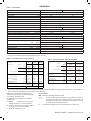
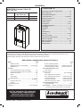
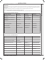
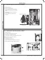
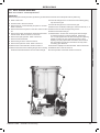
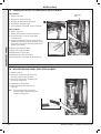
Combi 30 & 35
Installation and Servicing Instructions
FAN POWERED HIGH EFFICIENCY
MODULATING DOMESTIC CONDENSING
GAS COMBINATION BOILER
CE/PI No. 86-CL-38
Combi 30 - GC No. 47-930-04
Combi 35 - GC No. 47-930-05
These instructions must be left either with the
user or next to the site gas meter.
Keston Heating
PO Box 103, National Avenue, Kingston Upon Hull, HU5 4JN
Tel. +44 (0) 1482 443005 Fax. +44 (0) 1482 467133
email : [email protected] web : www.keston.co.uk
COMPLIANT WITH BUILDING REGULATION PART L1 & L2
SEDBUK A RATED
2
Keston Combi - Installation and Servicing
Notes for the installer
For any technical queries pleAse ring the KESTON
installer/technical helpline : 01482 443005
NOTE. BOILER RESET PROCEDURE To reset boiler, turn mode knob to reset position and immediately turn knob back to required setting.
The boiler will repeat the ignition sequence if a heat demand is present.
DOCUMENT amendments
Relevant Installation changes implemented in this book from Mod Level...... A02 (Oct 12) and A03 (Feb 14)
Page 11
Water Treatment - Addition of Adey Professional Heating Solutions
Page 31
Item “3” added to Electrical Installation
Statement added ref to commissioning process of combustion
Page 67
New Page Added - Benchmark Commissiong & Servicing Section
Page 68 & 69
New updated Commissioning Checklist & Service Record Sheets
Page 70 & 71
New pages added, Flowchart for CO Level and Combustion Ratio Check on Commissioning a Condensing Boiler
Keston reserve the right to vary specification without notice
Keston Combi - Installation and Servicing
3
general
Table 1 - General Data
Keston Combi
30
35
Gas supply
2H - G20 - 20mbar
Gas Supply Connection
15mm copper compression
Injector Size
(mm)
Inlet Connection
DHW
15mm copper compression
Outlet Connection
DHW
15mm copper compression
CH
22mm copper compression
CH
22mm copper compression
Flow Connection
Return Connection
Flue Terminal Diameter
4.65
4.9
mm (in)
Average Flue Temp-Mass Flow Rate
50 (nominal)
68 C - 13g/s
(DHW)
Maximum Working Pressure (Sealed Systems)
bar (lb/in2)
Maximum Domestic Hot Water Inlet Pressure
bar (lb/in2)
Minimum Domestic Hot Water Inlet Pressure*
bar (lb/in2)
73ºC - 15g/s
o
2.5 (36.3)
10.0 (145)
1.3 (18.9)
1.3 (18.9)**
Electrical Supply
230 V ~ 50 Hz.
Power Consumption
W
152
Fuse Rating
177
External : 3A
Water content
Internal : T4H HRC L250 V
CH
litre (gal)
1.2 (0.26)
DHW
litre (gal)
0.5 (0.11)
Packaged Weight
kg (lb)
37.8 (83.3)
38 (83.8)
Maximum Installation Weight
kg (lb)
32.8 (72.3)
33 (72.8)
Boiler Casing Size
Height
mm (in)
700 (27.5)
Width
mm (in)
395 (15.5)
Depth
mm (in)
278 (11)
*Required for maximum flow rate. Boiler operates down to 2 l/min DHW delivery
** In areas of low water pressure the DHW restrictor can be removed
Table 2 - Performance Data - Central Heating
Max.
Boiler Input :
Boiler Input ‘Q’
Nett CV
kW
(Btu/h)
Gross CV
kW
(Btu/h)
Gas Consumption
Min. 30
Table 3 - Performance Data - Domestic Hot Water
Maximum DHW Input :
Min. 35
24.3
6.1
7.1
(82,900)
(20,700)
(24,100)
27.0
6.7
7.9
Nett CV
(Btu/h)
Gross CV
(92,000)
(23,000)
(26,900)
2.512
0.623
0.734
(ft3/h)
(89)
(22)
(25.9)
Gas Consumption
DHW Output
kW
(Btu/h)
Condensing
kW
40 C Mean Water temp.
o
(Btu/h)
Seasonal efficiency*
NOx Classification
DHW Flow Rate
24.2
6.1
7.1
(20,700)
(24,100)
at 35°C temp. rise.
25.6
6.4
7.5
DHW Specific Rate
(87,400)
(21,800)
(25,500)
SEDBUK 2005
91.1%
91%
SEDBUK 2009
89%
88.9%
35
35.4
(103,600)
(120,900)
39.3
(115,000)
(134,200)
m3/h
3.135
3.658
(ft3/h)
(111)
(129)
kW
30.3
35.3
(103,300)
(120,500)
(Btu/h)
(82,600)
30
30.4
33.7
Maximum
Boiler Output :
Non Condensing
kW
(Btu/h)
m3/h
70oC Mean Water temp.
kW
l/min
12.4
14.5
(gpm)
(2.8)
(3.2)
l/min
14.5
16.9
(gpm)
(3.2)
(3.7)
CLASS 5
* The value is used in the UK Government’s Standard Assessment Procedure (SAP) for energy rating of dwellings. The test data from
which it has been calculated have been certified by a notified body.
Note. Gas consumption is calculated using a
calorific value of 38.7 MJ/m3 (1038 Btu/ft3) gross
or 34.9 MJ/m3 (935 Btu/ft3) nett
To obtain the gas consumption at a different
calorific value:
a. For l/s - divide the gross heat input
(kW) by the gross C.V. of the gas (MJ/m3)
b. For ft3/h - divide the gross heat input (Btu/h)
by the gross C.V. of the gas (Btu/ft3)
Key to symbols
PMS=Maximum operating pressure of water
C13 C53 =
I2H
A room sealed appliance designed for connection via ducts to
a horizontal terminal, which admits fresh air to the burner and
discharges the products of combustion to the outside. The fan is
up stream of the combustion chamber.
=An appliance designed for use on 2nd Family gas, Group H only.
c. For m3/h - multiply l/s by 3.6.
4
Keston Combi - Installation and Servicing
general
KESTON Combi 30 & 35
Natural Gas only
Boiler sizeG.C. Appliance No.PI No.
(Benchmark No.)
30
35
47-930-04
47-930-05
86 CL 38
86 CL 38
Contents
Benchmark Commissioning Checklist ...................... 66
Boiler Clearances .......................................................... 9
Boiler Exploded Diagram ............................................ 12
Condensate Drain ........................................... 8,22,23,39
Electrical Connections ................................................ 25
Electrical Supply ........................................................... 8
Fault Finding ........................................................... 57-63
Flue System ............................................................ 14-17
Gas Safety Regulations ................................................ 7
Gas Supply ..................................................................... 8
Installation ............................................................... 12-36
Pump ............................................................................ 50
Safe Handling ................................................................. 6
Servicing ................................................................. 37-56
Short List of Parts ....................................................... 64
Thermostatic Radiator Valves ...................................... 8
Water and Systems ........................................... 8, 10-11
Water Connections ...................................................... 24
Water Treatment ..........................................................11
Wiring Diagram ............................................................ 30
For GB, to comply with Building Regulations Part L1 (Part 6 in Scotland) the boiler should be fitted in accordance with the
manufacturer’s instructions. Self-certification that the boiler has been installed to comply with Building Regulations can be
demonstrated by completing and signing the Benchmark Commissioning Checklist.
Before installing this boiler, read the Code of Practice sheet at the rear of this book.
Benchmark Commissioning Checklist Details
Boiler
Page
Make and model.......................................................... 5
Appliance serial no. on data badge ........... Front Cover
SEDBUK No. %........................................................... 4
Controls
Time and temperature control to heating.................. 26
Time and temperature control to hot water .............. 26
Heating zone valves................................................. n/a
TRV’s.......................................................................... 8
Auto bypass................................................................ 8
Boiler interlock............................................................. 8
For ..................................................................... all boilers
Flushing to BS.7593.................................................. 11
Inhibitor..................................................................... 11
Central heating mode
Heat input....................................................to be calculated
Page
Burner operating pressure....................................... n/a
Central heating flow temp.............measure and record
Central heating return temp..........measure and record
For combination boilers only
Scale reducer............................................................ 11
Hot water mode
Heat input.............................................to be calculated
Max. operating burner pressure............................... n/a
Max. operating water pressure......... measure & record
Cold water inlet temp....................... measure & record
Hot water outlet temp....................... measure & record
Water flow rate at max. setting......... measure & record
For condensing boilers only
Condensate drain...................................................... 22
For all boilers: complete, sign & hand over to customer
For assistance see Technical Helpline on the back page
NOTE TO THE INSTALLER: COMPLETE
THE BENCHMARK COMMISSIONING
CHECKLIST AND LEAVE THESE
INSTRUCTIONS WITH APPLIANCE
Keston Combi - Installation and Servicing
5
general
INTRODUCTION
Safe Handling
The Keston Combi boiler is a wall mounted, full sequence,
automatic spark ignition, low water content, fanned flue, high
efficiency, condensing, combination gas boiler.
This boiler may require 2 or more operatives to move it to its
installation site, remove it from its packaging base and during
movement into its installation location. Manoeuvring the boiler
may include the use of a sack truck and involve lifting, pushing and
pulling.
Note. Due to the high efficiency of the boiler a plume of water
vapour will form at the terminal during operation.
Central heating (CH) output is fully modulating with a range of:
30
6.1 to 24.2kW (20,700 to 82,600 Btu/h)
35
7.1 to 24.2kW (24,100 to 82,600 Btu/h)
Instantaneous domestic hot water (DHW) output is also fully
modulating with a maximum of :
30
30.3kW (103,300 Btu/h)
35
35.3kW (120,500 Btu/h)
The boiler is supplied fully assembled with DHW plate heat
exchanger, diverter valve, circulating pump, pressure gauge,
safety valve and CH expansion vessel.
Variable CH and DHW temperature controls are fitted on the user
control and the boiler features a DHW preheat facility.
The boiler includes as standard:
-
Automatic bypass
-
Boiler frost protection
-
Daily pump and diverter valve exercise.
-
Weather Compensation Kit
Caution should be exercised during these operations.
Operatives should be knowledgeable in handling techniques when
performing these tasks and the following precautions should be
considered:
• Grip the boiler at the base.
• Be physically capable.
• Use personal protective equipment as appropriate, e.g. gloves,
safety footwear.
During all manoeuvres and handling actions, every attempt should
be made to ensure the following unless unavoidable and/or the
weight is light.
•
•
•
•
•
•
•
Keep back straight.
Avoid twisting at the waist.
Avoid upper body/top heavy bending.
Always grip with the palm of the hand.
Use designated hand holds.
Keep load as close to the body as possible.
Always use assistance if required.
The boiler casing is of white painted mild steel.
Optional extra kits
The boiler temperature controls are visible located in the control
panel on the front of the boiler.
• Electronic Programmable Room Thermostat kit
The heat exchanger is manufactured from cast aluminium.
The boiler is suitable for connection to fully pumped, sealed
heating systems ONLY. Adequate arrangements for completely
draining the system by provision of drain cocks MUST be provided
in the installation pipework.
• Electronic Timer (7 day) kit
•Stand Off kit
• Air Terminal Finishing Kit
• Flue Sleeve Kit
Pipework from the boiler is routed downwards.
operation
With no demand for CH, the boiler fires only when DHW is drawn
off, or periodically for a few seconds without any DHW draw-off, in
order to maintain the DHW calorifier in a heated condition. This
only occurs if pre-heat knob is in the ‘ON’ period.
When there is a demand for CH, the heating system is supplied at
the selected temperature of between 45oC and 83oC, until DHW
is drawn off. The full output from the boiler is then directed via
the diverter valve to the plate heat exchanger to supply a nominal
DHW draw-off of:
30
12.4 l/min at 35 oC temperature rise.
35
14.5 l/min at 35 oC temperature rise.
When using the outside sensor provided please refer to page 27.
The DHW draw off rate specified above is the nominal that the
boiler flow regulator will give. Due to system variations and
seasonal temperature fluctuations DHW flow rates/temperature
rise will vary, requiring adjustment at the draw off tap.
At low DHW draw-off rate the maximum temperature is limited to
64 oC by the modulating gas control.
The boiler features a comprehensive diagnostic system which
gives detailed information on the boiler status when operating,
and performance of key components to aid commissioning and
fault finding.
6
Keston Combi - Installation and Servicing
general
Safety
Location of boiler
Current Gas Safety (installation and use) regulations or rules
in force:
The boiler must be installed on a flat and vertical internal wall,
capable of adequately supporting the weight of the boiler and any
ancillary equipment.
The appliance is suitable only for installation in GB and IE and
should be installed in accordance with the rules in force.
In GB, the installation must be carried out by a Gas Safe
Registered Engineer. It must be carried out in accordance with
the relevant requirements of the:
• Gas Safety (Installation and Use) Regulations
The boiler may be fitted on a combustible wall and insulation
between the wall and the boiler is not necessary, unless required
by the local authority.
For electrical safety reasons there must be no access available
from the back of the boiler.
• The appropriate Building Regulations either The Building
Regulations, The Building Regulations (Scotland), Building
Regulations (Northern Ireland).
The boiler must not be fitted outside.
• The Water Fittings Regulations or Water byelaws in Scotland.
If the boiler is to be fitted in a timber framed building it should be
fitted in accordance with the Institute of Gas Engineering document
IGE/UP/7:2006 Edition 2.
• The Current I.E.E. Wiring Regulations.
Where no specific instructions are given, reference should be
made to the relevant British Standard Code of Practice.
In IE, the installation must be carried out by a Registered Gas
Installer (RGII) and installed in accordance with the current edition
of I.S.813 “Domestic Gas Installations”, the current Building
Regulations and reference should be made to the current ETCI
rules for electrical installation.
Detailed recommendations are contained in the following British
Standard Codes of Practice:
BS. 5440:1 Flues (for gas appliances of rated input not exceeding 70 kW).
BS. 5440:2 Ventilation (for gas appliances of rated input not
exceeding 70 kW).
BSEN. 12828:2003 Heating Systems in buildings: Design for
water based heating systems.
Timber Framed Buildings
Bathroom Installations
This appliance is rated IP20.
The boiler may be installed in any room or internal space, although
particular attention is drawn to the requirements of the current
IEE (BS.7671) Wiring Regulations and the electrical provisions
of the building regulations applicable in Scotland, with respect to
the installation of the boiler in a room or internal space containing
a bath or shower. For IE reference should be made to the current
ETCI rules for electrical installations and I.S. 813:2002.
If the appliance is to be installed in a room containing a bath or
shower then, providing water jets are not going to be used for
cleaning purposes (as in communal baths/showers), the appliance
must be installed beyond Zone 2, as detailed in BS.7671.
BSEN 12831:2003 Heating Systems in buildings: Method for
calculation of the design heat load.
BSEN 14336:2004
Heating Systems in buildings: Installation
and commissioning of water based heating
systems.
BS. 5546
Installation of gas hot water supplies for domestic
purposes (2nd Family Gases)
BS. 6798
Installation of gas fired hot water boilers of rated
input not exceeding 70 kW.
BS. 6891
Ceiling
Recessed
window
Zone 2
2.25m
Zone 1
0.6m
Low pressure installation pipes.
Health & Safety Document No. 635.
Zone 0
The Electricity at Work Regulations, 1989.
3G8913a
The manufacturer’s notes must NOT be taken, in any way, as
overriding statutory obligations.
Compartment Installations
IMPORTANT. These appliances are CE certificated for safety
and performance. It is, therefore, important that no external
control devices, e.g. flue dampers, economisers etc., are
directly connected to these appliances unless covered by
these Installation and Servicing Instructions or as otherwise
recommended by Keston in writing. If in doubt please enquire.
An existing cupboard or compartment may be used, provided that
it is modified for the purpose.
Any direct connection of a control device not approved by Keston
could invalidate the certification and the normal appliance
warranty. It could also infringe the Gas Safety Regulations and
the above regulations.
SAFE HANDLING OF SUBSTANCES
No asbestos, mercury or CFCs are included in any part of the
boiler or its manufacture.
A compartment used to enclose the boiler should be designed and
constructed specially for this purpose.
In both cases, details of essential features of cupboard /
compartment design, including airing cupboard installation, are to
conform to the following:
• BS 6798 (No cupboard ventilation is required - see ‘Air Supply’
for details).
• The position selected for installation MUST allow adequate
space for servicing in front of the boiler.
• For the minimum clearances required for safety and
subsequent service, see the wall mounting template and
Frame 1. In addition, sufficient space may be required to
allow lifting access to the wall mounting plate.
• The boiler must be installed on a fire resistant surface.
Keston Combi - Installation and Servicing
7
general
GAS SUPPLY
Water circulation system
The local gas supplier should be consulted, at the installation
planning stage, in order to establish the availability of an adequate
supply of gas. An existing service pipe must NOT be used without
prior consultation with the local gas supplier.
Important.
The boiler MUST be installed on a gas supply with a governed
meter only.
The central heating system should be in accordance with BS.6798
and, in addition, for smallbore and microbore systems, BS.5449.
A gas meter can only be connected by the local gas supplier or
by a Gas Safe Registered Engineer. In IE by a Registered Gas
Installer (RGII).
Water treatment - see Frame 5
Boiler Control Interlocks
An existing meter should be checked, preferably by the gas
supplier, to ensure that the meter is adequate to deal with the rate
of gas supply required.
Central heating systems controls should be installed to ensure
the boiler is switched off when there is no demand for heating, in
compliance with Building Regulations.
It is the responsibility of the Gas Installer to size the gas
installation pipework in accordance with BS6891:2005. Whilst the
principle of the 1:1 gas valve ensures the Keston Combi range
is able to deliver its full output at inlet pressures as low as 14mb,
other gas appliances in the property may not be as tolerant.
When operating pressures are found to be below the minimum
meter outlet of 19mb these should be checked to ensure this is
adequate for correct and safe operation.
Heating systems utilising full thermostatic radiator valve control
of temperature in individual rooms should also be fitted with a
room thermostat controlling the temperature in a space served by
radiators not fitted with such a valve.
Allowing for the acceptable pressure loss of 1mb across the
installation pipework, it can be assumed that a minimum permitted
operating pressure of 18mb will be delivered to the inlet of
the appliance. (Reference BS 6400-1 Clause 6.2 Pressure
Absorption).
The external gas cock could further reduce the operating pressure
when measured at its test point. The pressure drop is relative to
the heat input to the boiler (kW), refer to graph below.
A minimum length of 1 metre of copper pipe MUST be fitted
to both flow and return connections from the boiler before
connection to any plastic piping.
When thermostatic radiator valves are used, the space heating
temperature control over a living / dining area or hallway having
a heating requirement of at least 10% of the minimum boiler heat
output should be achieved using a room thermostat, whilst other
rooms are individually controlled by thermostatic radiator valves.
However, if the system employs thermostatic radiator valves on all
radiators, or two port valves, then a bypass circuit must be fitted
with an automatic bypass valve to ensure a flow of water should
all valves be in the closed position.
Electrical supply
Warning.
This appliance must be earthed.
Wiring external to the appliance MUST be in accordance with
the current I.E.E. (BS.7671) Wiring Regulations and any local
regulations which apply. For IE reference should be made to the
current ETCI rules for electrical installations.
The mains supply to the boiler and system wiring centre shall
be through one common fused double pole isolator and for
new heating systems, and where practical replacement boiler
installations, the isolator shall be situated adjacent to the
appliance.
Condensate drain
Refer to Frames 20 & 21
Important.
Installation pipes must be fitted in accordance with BS.6891. In IE
refer to IS.813:2002.
The complete installation MUST be tested for gas tightness and
purged as described in the above code.
A condensate drain is provided on the boiler. This drain must be
connected to a drainage point on site. All pipework and fittings in
the condensate drainage system MUST be made of plastic - no
other materials may be used.
Important.
Any external runs must be in accordance with BS 6798.
The drain outlet on the boiler is sized for standard 21.5mm (3/4”)
overflow pipe. It is a universal fitting to allow use of different
brands of pipework.
8
Keston Combi - Installation and Servicing
general
1boiler dimensions, services & clearances
all dimensions in mm
The boiler connections are made on the boiler connection tails.
Refer to Frame 22.
The following minimum clearances must be maintained for
operation and servicing.
Additional space will be required for installation, depending upon
site conditions.
2.5
from case
2.5
30mm
Minimum Top Clearance
395
62
198
155
89
Air
Flue
700
100 *
395
400
43
65
57
38
39
65
Gas Inlet
Front clearance
The minimum front clearance when built in to a cupboard is 5mm
from the cupboard door but 450mm overall clearance is still
required, with the cupboard door open, to allow for servicing.
* Bottom clearance
Bottom clearance after installation can be reduced to 5mm.
This must be obtained with an easily removable panel, to enable
the consumer to view the system pressure gauge, and to provide
the 100mm clearance required for servicing.
Keston Combi - Installation and Servicing
9
general
2
system requirements - Central Heating
Notes
a. The method of filling, refilling, topping up or flushing sealed
primary hot water circuits from the mains via a temporary
hose connection is only allowed if acceptable to the local
water authority.
Safety valve setting
bar
3.0
Vessel charge pressure
bar
0.5 to 0.75
System pre-charge pressure bar
System volume
(litres)
b. Antifreeze fluid, corrosion and scale inhibitor fluids suitable
for use with boilers having aluminium heat exchangers may
be used in the central heating system.
General
1. The installation must comply with all relevant national and local
regulations.
2. The installation should be designed to work with flow
temperatures of up to 86 oC.
3. All components of the system must be suitable for a working
pressure of 3 bar and temperature of 110 oC. Extra care should
be taken in making all connections so that the risk of leakage is
minimised.
The following components are incorporated within the appliance:
a. Circulating pump.
b. Safety valve, with a non-adjustable preset lift pressure of 3
bar.
c. Pressure gauge, covering a range of 0 to 4 bar.
d. An 8-litre expansion vessel, with an initial charge pressure
of 0.75 bar.
None
1.0
Expansion vessel
volume (litres)
25
1.6
1.8
50
3.1
3.7
75
4.7
5.5
100
6.3
7.4
125
7.8
9.2
150
9.4
11.0
175
10.9
12.9
190
11.9
14.0
200
12.5
14.7
250
15.6
18.4
300
18.8
22.1
0.063
0.074
For other system volumes
multiply by the factor access
Water Flow Rate and Pressure Loss
Max CH Output
kW
(Btu/h)
Water flow rate
Temperature Differential
l/min
17.3
(gal/min)
(3.8)
o
C
( F)
o
Head available for
system
24.2
(82,600)
20
(36)
m.w.g.
3.4
(ft.w.g.)
(11.1)
4. ‘Make-up’ Water. Provision must be made for replacing water
loss from the system, either :
a. From a manually filled ‘make-up’ vessel with a readily visible 5.Filling
water level. The vessel should be mounted at least 150mm
The system may be filled by the following method:
above the highest point of the system and be connected
through a non-return valve to the system, fitted at least Where the mains pressure is excessive a pressure
150mm below the ‘make-up’ vessel on the return side of
reducing valve must be used to facilitate filling.
the radiators. or
a. Thoroughly flush out the whole system with cold
b. Where access to a ‘make-up’ vessel would be difficult, by
water.
pre-pressurisation of the system.
b.
Fill and vent the system until the pressure gauge
The maximum cold water capacity of the system should
registers 1bar and examine for leaks. Refer to Frame
not exceed 143 litres, if not pressurized. However, if
22 for filling detail.
the system is to be pressurized, the efficiency of the
c.
Check the operation of the safety valve by raising the
expansion vessel will be reduced and a larger vessel
water pressure until the valve lifts. This should occur
(or smaller system volume) may be necessary. If the
within 0.3bar of the preset lift pressure.
capacity of the vessel is not considered sufficient for this,
or for any other reason, an additional vessel must be
d. Release water from the system until the installed on the RETURN to the boiler.
minimum system design pressure is reached; 1.0 bar if the system is to be pre-pressurised.
Guidance on vessel sizing is given in Table above.
continued . . . . . .
10
Keston Combi - Installation and Servicing
general
3
system requirements cont’d
4
Domestic Hot Water
1. The domestic hot water service must be in accordance with
BS 5546 and BS 6700.
2. Refer to Table 1 for minimum and maximum working
pressures. In areas of low mains water pressures the
domestic hot water regulator may be removed from the DHW
flow turbine cartridge. Refer to Frame 70. The boiler will
require the flow rate to be set to obtain a temperature rise of
35oC at the tap furthest from the boiler.
3. The boiler is suitable for connection to most types of washing
machine and dishwasher appliances.
4. When connecting to suitable showers, ensure that:
a. The cold inlet to the boiler is fitted with an approved antivacuum or syphon non-return valve.
b. Hot and cold water supplies to the shower are of equal
pressure.
5.Hard Water Areas
Where the water hardness exceeds 200mg/litre, it is
recommended that a proprietary scale reducing device is
fitted into the boiler cold supply within the requirements of the
local water company.
Important
Provision must be made to accommodate the expansion of DHW
contained within the appliance, if a non-return valve is fitted to the
DHW inlet, or a water meter with a non-return valve is installed.
Cold water rising main and pipework in exposed areas need to
be suitably lagged to prevent freezing.
5water treatment
Central Heating
The Keston Combi range boiler has an aluminium alloy
heat exchanger.
Important.
The application of any other treatment to this product
may render the guarantee of Keston Invalid.
Keston recommend Water Treatment in accordance with the
Benchmark Guidance Notes on Water Treatment in Central
Heating Systems.
If water treatment is used Keston recommend only the use
of SCALEMASTER GOLD 100, Fernox, MBI, Adey MC1 or
Sentinel X100 inhibitors and associated water treatment
products, which must be used in accordance with the
manufacturers’ instructions.
Notes.
1. It is most important that the correct concentration of the
water treatment products is maintained in accordance
with the manufacturers’ instructions.
2. If the boiler is installed in an existing system any
unsuitable additives MUST be removed by thorough
cleansing. BS 7593:2006 details the steps necessary to
clean a domestic heating system.
3. In hard water areas, treatment to prevent lime scale may
be necessary - however the use of artificially softened
water is NOT permitted.
4. Under no circumstances should the boiler be fired
before the system has been thoroughly flushed.
Keston Combi - Installation and Servicing
system balancing
The boiler does not normally need a bypass but at least
some radiators on the heating circuit, of load of at least
10% of the minimum boiler output, must be provided with
twin lockshield valves so that this minimum heating load
is always available. See note regarding thermostatic
radiator valves on page 8.
Note. Systems incorporating zone valves which could
completely cut off the flow through the system must also
include a bypass.
Balancing
1. Set the programmer to ON.
Close the manual or thermostatic valves on all
radiators, leaving the twin lockshield valves (on the
radiators referred to above) in the open position.
Turn up the room thermostat and adjust the
lockshield valve to give an uninterrupted flow through
the radiator.
These valves should now be left as set.
2. Open all manual or thermostatic radiator valves
and adjust the lockshield valves on the remaining
radiators, to give around 20oC temperature drop at
each radiator.
3. Adjust the room thermostat and programmer to
normal settings.
Domestic Hot water
In hard water areas where mains water can exceed 200ppm
Total Hardness (as defined by BS 7593:2006 Table 2) a scale
reducing device should be fitted into the boiler cold supply within
the requirements of the local water company. The use of artificially
softened water, however, is not permitted.
Keston recommend the use of Fernox Quantomat, Sentinel
Combiguard or Calmag CalPhos I scale reducing devices together
with scalemaster in-line scale inhibitor branded Ideal, which must
be used in accordance with the manufacturers’ instructions.
For further information contact:
Fernox Cookson Electronics
Forsyth Road, Sheerwater, Woking, Surrey GU21 5RZ
+44 (0) 870 601 500
Sentinel Performance Solutions
The Heath Business & Technical Park, Runcorn, Cheshire WA7 4QX
Tel: 0800 389 4670
www.sentinel-solutions.net
Scalemaster Water Treatment Products
Emerald Way, Stone, Staffordshire ST15 0SR
Tel: +44 (0) 1785 811636
Calmag Ltd.
Unit 3-6, Crown Works, Bradford Road, Sandbeds, Keighley,
West Yorkshire BD20 5LN
Tel: +44 (0) 1535 210 320
Adey Professional Heating Solutions
Gloucester Road, Cheltenham GL51 8NR
Tel: +44 (0) 1242 546700
11
INSTALLATION
INSTALLATION
6 boiler assembly - exploded view
104
105
106
107
108
110
111
112
113
114
115
116
117
118
119
120 Flow Group Manifold
121 Plate Heat Exchanger
127 Flow Sensor Hall Effect
128 Flow Turbine Cartridge
131 Water Pressure Transducer
135 Pressure Gauge
136 Safety Valve Drain Pipe
203 Gas Cock
204 Pipe - Gas Inlet
205 Gas Valve
206 Pipe - Gas Injector
211 Injector Assembly
214 Venturi
215 Fan
217 Burner
CH Return Valve
CH Flow Valve
DHW Inlet & Outlet
Filling Loop
Pump Head
Air Vent Pump
Diverter Valve Head
Diverter Valve Cartdrige
Pressure Relief Valve
Pipe - PRV Outlet
Pipe - Flow
Pipe - Return
Pipe - Expansion Vessel
Expansion Vessel
Return Group Manifold
218
219
223
224
227
228
229
231
301
302
303
304
306
307
308
309
313
314
324
325
326
332
401
503
504
505
506
507
136
512
332
Gasket - Burner
Sump Clean Out Cover
Flue Manifold
Flue Manifold Top
Clamp Retaining Flue Turret
Hose Condensate Internal
Siphon Trap
Condensate Outlet Connection
Ctrs Box