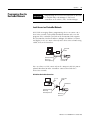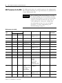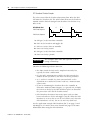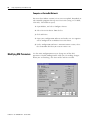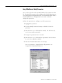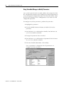
1
DeviceNet
Interface
Catalog Number 1761-NET-DNI
User Manual
Important User Information
Solid state equipment has operational characteristics differing from those of
electromechanical equipment. Safety Guidelines for the Application,
Installation and Maintenance of Solid State Controls (publication SGI-1.1
available from your local Rockwell Automation sales office or online at
http://literature.rockwellautomation.com) describes some important
differences between solid state equipment and hard-wired electromechanical
devices. Because of this difference, and also because of the wide variety of
uses for solid state equipment, all persons responsible for applying this
equipment must satisfy themselves that each intended application of this
equipment is acceptable.
In no event will Rockwell Automation, Inc. be responsible or liable for
indirect or consequential damages resulting from the use or application of
this equipment.
The examples and diagrams in this manual are included solely for illustrative
purposes. Because of the many variables and requirements associated with
any particular installation, Rockwell Automation, Inc. cannot assume
responsibility or liability for actual use based on the examples and diagrams.
No patent liability is assumed by Rockwell Automation, Inc. with respect to
use of information, circuits, equipment, or software described in this manual.
Reproduction of the contents of this manual, in whole or in part, without
written permission of Rockwell Automation, Inc., is prohibited.
Throughout this manual, when necessary, we use notes to make you aware
of safety considerations.
WARNING
IMPORTANT
ATTENTION
Identifies information about practices or circumstances that can cause
an explosion in a hazardous environment, which may lead to personal
injury or death, property damage, or economic loss.
Identifies information that is critical for successful application and
understanding of the product.
Identifies information about practices or circumstances that can lead
to personal injury or death, property damage, or economic loss.
Attentions help you identify a hazard, avoid a hazard, and recognize
the consequence
SHOCK HAZARD
Labels may be on or inside the equipment, for example, a drive or
motor, to alert people that dangerous voltage may be present.
BURN HAZARD
Labels may be on or inside the equipment, for example, a drive or
motor, to alert people that surfaces may reach dangerous
temperatures.
Summary of Changes
The information below summarizes the changes to this manual since
the last revision.
Revision bars in the margin identify updated information. The
following changes are included in this version of the document.
Change
3
Page
Added note that programming over a DeviceNet network is
available only with RSLogix 5/500-based controllers.
21
Added note that remote access to a DeviceNet network is
available only with RSLogix 5/500-based controllers.
22
Publication 1761-UM005B-EN-P - October 2006
4
Summary of Changes
Publication 1761-UM005B-EN-P - October 2006
Table of Contents
Preface
About This Publication . . . . . . . .
Who Should Use This Publication
Conventions . . . . . . . . . . . . . . . .
Additional Resources. . . . . . . . . .
.
.
.
.
.
.
.
.
.
.
.
.
.
.
.
.
.
.
.
.
.
.
.
.
.
.
.
.
.
.
.
.
.
.
.
.
.
.
.
.
.
.
.
.
.
.
.
.
.
.
.
.
.
.
.
.
.
.
.
.
.
.
.
.
.
.
.
.
.
.
.
.
.
.
.
.
.
.
.
.
.
.
.
.
7
7
7
8
Chapter 1
Overview
Introduction . . . . . . . . . . . . . . . . . . . . . . . . . . . . . . . . . . . . . 9
Operating Modes . . . . . . . . . . . . . . . . . . . . . . . . . . . . . . . . . 9
Device Compatibility . . . . . . . . . . . . . . . . . . . . . . . . . . . . . . . 9
Chapter 2
Quick Start
Configure Peer-to-peer Messaging . . . . . . . . . . . . . . . . . . . . 11
Configuring Master/Slave I/O . . . . . . . . . . . . . . . . . . . . . . . 13
Chapter 3
Operation
Modes of Use . . . . . . . . . . . . . . . . . . . . . .
DeviceNet I/O . . . . . . . . . . . . . . . . . . . . .
Network Configuration Software . . . . . . . .
Messaging Services . . . . . . . . . . . . . . . . . .
Programming Over the DeviceNet Network
.
.
.
.
.
.
.
.
.
.
.
.
.
.
.
.
.
.
.
.
.
.
.
.
.
.
.
.
.
.
.
.
.
.
.
.
.
.
.
.
.
.
.
.
.
.
.
.
.
.
.
.
.
.
.
.
.
.
.
.
.
.
.
.
.
17
17
18
19
21
European Communities (EC) Directive Compliance
Safety Considerations . . . . . . . . . . . . . . . . . . . . . .
Mounting . . . . . . . . . . . . . . . . . . . . . . . . . . . . . . .
Network Port Wiring . . . . . . . . . . . . . . . . . . . . . . .
Cable Selection Guide . . . . . . . . . . . . . . . . . . . . . .
.
.
.
.
.
.
.
.
.
.
.
.
.
.
.
.
.
.
.
.
.
.
.
.
.
.
.
.
.
.
.
.
.
.
.
23
24
24
26
26
Chapter 4
Installation and Wiring
Chapter 5
DNI Configuration Parameters and Information About DNI Series B . . . . . . . . . . . . . . . . . . . . . 27
EDS Parameters for the DNI . . . . . . . . . . . . . . . . . . . . . . . . 28
Programming Notes
Programming Notes. . . . . . . . . . . . . . . . . . . . . . . . . . . . . . . 49
Chapter 6
Setup, Programming, and
Troubleshooting
5
DNI Software Files . . . . . . . . . . . . . . . . . . .
Setting Up Network Configuration Software .
Commissioning the DNI . . . . . . . . . . . . . . .
Programming Over the DeviceNet Network .
Modifying DNI Parameters. . . . . . . . . . . . . .
Troubleshooting . . . . . . . . . . . . . . . . . . . . .
Fault Conditions . . . . . . . . . . . . . . . . . . . . .
DNI Series A DeviceNet Class Codes . . . . . .
DNI Series B DeviceNet Class Codes . . . . . .
.
.
.
.
.
.
.
.
.
.
.
.
.
.
.
.
.
.
.
.
.
.
.
.
.
.
.
.
.
.
.
.
.
.
.
.
.
.
.
.
.
.
.
.
.
.
.
.
.
.
.
.
.
.
.
.
.
.
.
.
.
.
.
.
.
.
.
.
.
.
.
.
.
.
.
.
.
.
.
.
.
.
.
.
.
.
.
.
.
.
..
..
..
..
..
..
..
..
..
53
55
58
59
60
62
64
65
66
Publication 1761-UM005B-EN-P - October 2006
Table of Contents
6
Chapter 7
Application Examples
MicroLogix as I/O on the DeviceNet Network . . . . . . . . . . . 69
Example DNI Configuration Parameters . . . . . . . . . . . . . . . . 70
Example Ladder Logic . . . . . . . . . . . . . . . . . . . . . . . . . . . . . 71
Chapter 8
Explicit Messaging (DNI Series B Using DF1 Protocol for Explicit Messages Over a DeviceNet
Network . . . . . . . . . . . . . . . . . . . . . . . . . . . . . . . . . . . . . . . 78
Only)
Routing Profile Configuration. . . . . . . . . . . . . . . . . . . . . . . . 79
Explicit Messaging Examples . . . . . . . . . . . . . . . . . . . . . . . . 80
Appendix A
Specifications
Physical Specifications. . . . . . . . . . . . . . . . . . . . . . . . . . . . . 85
DeviceNet Specifications . . . . . . . . . . . . . . . . . . . . . . . . . . . 85
Dimensions. . . . . . . . . . . . . . . . . . . . . . . . . . . . . . . . . . . . . 86
Glossary
Interface Basics . . . . . . . . . . . . . . . . . . . . . . . . . . . . . . . . . . 89
Terms and Abbreviations. . . . . . . . . . . . . . . . . . . . . . . . . . . 89
Index
Publication 1761-UM005B-EN-P - October 2006
Preface
About This Publication
This user manual introduces the DeviceNet Interface (DNI) and
explains the procedures you need to install, configure, and
commission the interface.
Who Should Use This
Publication
Use this manual if you are responsible for designing, installing,
programming, or troubleshooting control systems that use
Allen-Bradley controllers on a DeviceNet network.
You should have a basic understanding of Allen-Bradley
programmable controllers and DeviceNet technology. You should
understand programmable controllers and be able to interpret the
ladder logic instructions required to control your application. If you
do not, contact your local Allen-Bradley representative for information
on available training courses before using this product.
Conventions
7
Text that is
Identifies
Bold
Emphasis, not used within programming text
Italic
Software variables and configurable catalog numbers
courier
Example programming code, shown in a monospace font so
you can identify each character and space
Publication 1761-UM005B-EN-P - October 2006
8
Preface
Additional Resources
Resource
Description
MicroMentor, publication 1761-RM001
Information on understanding and applying micro
controllers.
AIC+ Advanced Interface Converter and DeviceNet
Mounting instructions for the DeviceNet Interface
Interface Installation Instructions, publication 1761-IN002
MicroLogix 1000 Controllers User Manual,
publication 1761-UM003
Information on MicroLogix 1000 Controllers
MicroLogix 1500 Controllers User Manual,
publication 1764-UM001
Information on MicroLogix 1500 Controllers
SLC 500™ Modular Hardware Style User Manual,
publication 1747-UM011
Information on SLC Controllers
PLC User Manual, publication 1785-UM001
Information on PLC® Controllers
SLC 500 and MicroLogix 1000 Instruction Set Reference
Manual, publication 1747-RM001
A reference manual that contains status file data and
instruction set information
DeviceNet Manager Software User Manual,
publication 1787-UM053
Information on DeviceNet Manager
1747 DeviceNet Scanner Installation Instructions,
publication 1747-IN058
Information on 1747 DeviceNet Scanner
1747 DeviceNet Scanner User Manual,
publication 1747-UM655
1771 DeviceNet Scanner Configuration Manual,
publication 1771-UM118
Information on 1771 DeviceNet Scanner
DeviceNet Cable System Planning and Installation
Manual, publication DNET-UM072
Planning and installing a DeviceNet cable system
Allen-Bradley Programmable Controller Grounding and
Wiring Guidelines, publication 1770-IN041
In-depth information on grounding and wiring
Allen-Bradley programmable controllers
Allen-Bradley Industrial Automation Glossary,
publication AG-QR071
A glossary of industrial automation terms and
abbreviations
Publication 1761-UM005B-EN-P - October 2006
Chapter
1
Overview
Introduction
The DeviceNet interface is a standalone, DIN-rail or panel mounted,
intelligent DeviceNet-to-DF1 protocol-conversion device that lets
existing DF1 devices communicate on a DeviceNet network. The DF1
device exchanges I/O data with a Master device and originates and
receives DF1 encapsulated DeviceNet messages across a DeviceNet
network.
The DNI provides a single DeviceNet connection point and a single
RS-232 connection. The DeviceNet port is isolated from the DNI
digital logic and RS-232 port.
The primary functions of the DNI are:
• Collect or receive input data from the DF1 device connected on
its RS-232 port and forward that data to a connected master on
DeviceNet network.
• Monitor output data received from the DeviceNet master and
write that data to the DF1 device.
• Allow DF1 devices to send and receive messages across the
DeviceNet network.
Operating Modes
The DNI can be used in either or both of the following modes.
• Peer-to-peer
• DeviceNet slave
Device Compatibility
The DNI can be used to interconnect the following devices.
• MicroLogix controllers
• DF1 Full Duplex compliant products, for example: PLC-5
programmable controllers, operator interface devices, and SLC
5/03™ and higher processors
9
Publication 1761-UM005B-EN-P - October 2006
10
Overview
Publication 1761-UM005B-EN-P - October 2006
Chapter
2
Quick Start
This chapter can help you to get started using the 1761-NET-DNI
DeviceNet Interface (DNI). We base the procedures here on the
assumption that you have an understanding of MicroLogix products.
You should understand electronic process control and be able to
interpret the ladder logic instructions required to generate the
electronic signals that control your application.
Because this is a start-up guide for experienced users, this chapter
does not contain detailed explanations about the procedures listed. It
does, however, reference other chapters in this book where you can
get more information.
If you have any questions or are unfamiliar with the terms used or
concepts presented in the procedural steps, always read the
referenced chapters and other recommended documentation before
trying to apply the information.
Configure Peer-to-peer
Messaging
Follow these steps to communicate with other controllers connected
to DNIs on a DeviceNet network.
1. Unpack and mount the DNI.
2. Connect the DNI to the DeviceNet network.
When power is first applied to the DNI, it resides at node 63 on
the network. The DNI out-of-box configuration is defaulted to
Autobaud; it synchronizes to the DeviceNet network baud rate.
3. Connect a DF1 device to the DNI.
The DF1 connection automatically enters the Autobaud mode; it
synchronizes to the attached DF1 device.
4. Connect to the DNI with your network configuration tool
(software such as the DNI Configuration Utility, RSNetWorx, or
DeviceNet Manager) and set the DNI to the desired node
number. This is called commissioning the DNI.
See Commissioning the DNI on page 58 for more details.
11
Publication 1761-UM005B-EN-P - October 2006
12
Quick Start
IMPORTANT
If your network consists entirely of DNIs (no master is present),
you must disable Autobaud on at least one DNI. It is
recommended that all DNIs be manually set to a specific baud
rate. This is to prevent multiple DNIs from hunting for a baud
rate at power-up.
5. To exchange data with other controllers over a DeviceNet
network, configure a message instruction inside each controller’s
program.
See Programming Over the DeviceNet Network on page 21 for
more information.
6. To send data to a specific controller on the network, enter the
destination DNI’s DeviceNet node address into the destination
parameter of a message instruction. Think of each
DNI/Controller pair as one unit.
EXAMPLE
To send a message from controller A (plugged into DNI number
5) to controller B (plugged into DNI number 10), controller A
must have a message instruction with a destination node
address of 10.
See the application example MicroLogix as I/O on the
DeviceNet Network on page 69 for an example ladder program.
Publication 1761-UM005B-EN-P - October 2006
Quick Start
Configuring Master/Slave
I/O
IMPORTANT
13
You must have the DNI’s EDS (electronic data sheet) file and
bitmap file (or icon) loaded into your configuration software.
See DNI Software Files on page 53 and Setting Up Network
Configuration Software on page 55 for more information.
Follow these steps to configure a DNI connected to a MicroLogix 1000
controller as a slave device to a DeviceNet master.
1. Unpack and mount the DNI.
2. Connect the DNI to the DeviceNet Network.
When power is first applied to the DNI, it resides at node 63 on
the network. The DNI out-of-box configuration is defaulted to
Autobaud; it synchronizes to the DeviceNet network baud rate.
3. Connect to the DNI with your network configuration tool
(software such as DeviceNet Manager or RSNetWorx) and set the
DNI to the desired node number. This is called node
commissioning.
4. Double-click on the DNI icon to open the DNI’s EDS.
5. For DNI Series A: set DNI Mode (parameter 17) to Standby mode
(0).
For DNI Series B: set I/O Scan Enable (parameter 12) to disable
(0) (default).
6. Click Save to Device.
Publication 1761-UM005B-EN-P - October 2006
14
Quick Start
To configure a MicroLogix 1000 controller as a slave device to a
DeviceNet master, set the parameters as shown in the following table.
MicroLogix 1000 Controller Parameter Settings
Parameter Number
Description
Range
Default Value
For this Example,
ENTER
Series A
Series B
4
1
Input Size
Series A: 1…16
Series B: 1…32
1 word
2 words
Not Applicable
2
Input Split Point
1…32
1 word
2 words
5
3
Input Type
Bit or Integer File
Integer File
Integer File
6
4
Input Data File
3…254
7
7
7
5
Input Word Offset
0…254
0
90
8
6
Output Size
Series A: 1…16
Series B: 1…32
1 word
2 words
9
8
Output Type
Bit or Integer File
Integer File
Integer File
10
9
Output Data File
3…254
7
7
11
10
Output Word Offset
0…254
1
95
14
11
DF1 Device
0…3:
0: Other
1: PLC
2: SLC/ Other
MicroLogix
3: MicroLogix 1000
3 = MicroLogix 1000
3 = MicroLogix 1000
3
12
DNI Series A:
Data Enable
DNI Series B:
I/O Scan Enable
(Polling Enable)
Disabled (0) or Enabled
(1)
Disabled (0)
Enabled (1)
12
13
DF1 Heartbeat
Series A: 2…10
Series B: 1…10
2
2
13
14
Data Scan Delay
(Polling Delay)
20…3000 ms
50 ms
100 ms
2
15
Message Timeout
0…2500 ms
0 ms
0 ms
Not Applicable
16
DF1 Substitute Address
0…64
64 = Disabled
64 = Disabled
15
17
DF1 Autobaud
Disabled (0) or Enabled
(1)
Enabled (1)
Enabled (1)
16
18
DF1 Baud Rate
0…5:
0: 38,400
1: 19,200
2: 9600
3: 4800
4: 2400
5: 1200
Series A: 2 = 9600
Series B: 1 = 19,200
n/a
1
19
DeviceNet Autobaud
Disabled (0) or Enabled
(1)
Enabled (1)
Enabled (1)
17
Not
Applicable
DNI Mode
Standby (0) or
Operational (1)
Operational (1)
Operational (1)
Publication 1761-UM005B-EN-P - October 2006
Quick Start
15
7. Click Modified Parameter, then OK.
8. Save to the configuration to the DNI.
In this configuration, the DNI provides two words (32 bits) of data.
The data is scanned (read), starting at address N7:90 of the attached
MicroLogix 1000 controller, at 100 msec intervals.
Data received (DeviceNet master output) is written to the MicroLogix
1000 controller whenever new (changed) data is detected by the DNI.
Two words of data will be written to Integer file 7, starting at word 95.
You must have the following rung programmed into the
MicroLogix 1000 controller:
IMPORTANT
N7:95
N7:90
7
7
At this point, the DNI is configured to be a slave on DeviceNet, but it
is not part of (owned by) a DeviceNet master/scanner.
To configure your DeviceNet scanner, refer to its manual. For the
1747-SDN, refer to the SLC 500 DeviceNet Scanner user manual,
publication 1747-UM655. For the 1771-SDN, refer to the PLC-5
DeviceNet Scanner user manual, publication 1771-UM118.
Publication 1761-UM005B-EN-P - October 2006
16
Quick Start
Publication 1761-UM005B-EN-P - October 2006
Chapter
3
Operation
Modes of Use
The DeviceNet Interface has three primary features.
• DeviceNet I/O
• Explicit Messaging
• Programming over DeviceNet network
DeviceNet I/O
IMPORTANT
All input and output comments are referenced from
the perspective of the DeviceNet Master.
The DNI is capable of being owned by a master on DeviceNet. This
functionality on DeviceNet is part of the I/O class of services, and
allows a master device to exclusively manage (own) another device’s
(a different node number) data and resources. This type of
relationship is functionally the same as a PLC with remote I/O. A PLC
uses the remote I/O chassis as distributed inputs and outputs. The
master/slave relationship on DeviceNet is exactly the same, except it
is being done over DeviceNet.
The amount of data available between devices that implement I/O
master/slave services is determined by the design of each device, and
is not a function of DeviceNet.
The DNI on DeviceNet is capable of handling 32 I/O words of data
with a DeviceNet I/O master for DNI Series A (64 for DNI Series B).
This is broken up into two data images: the input image and the
output image.
17
Publication 1761-UM005B-EN-P - October 2006
18
Operation
Input Image
The input image is a configurable array of 16-bit data words. The
image is configurable from 1…16 data words for DNI Series A (1…32
data words for DNI Series B). The actual data that resides in the input
image is delivered to the DeviceNet master by one of three
mechanisms.
• Polled: Where the DeviceNet Master sends a poll request with
output data and the DNI responds with its current input data.
• COS (Change of State): Where the DNI detects that data has
changed within the input image and automatically sends the
data to the DeviceNet Master.
• Cyclic: The DNI continuously sends the input image data to the
master at a user/scanner-defined time interval, regardless of
whether the data has changed.
Output Image
The output image is a configurable array of 16-bit data words. The
image is configurable from 1…16 data words for DNI Series A (1…32
data words for DNI Series B). The actual data that resides in the
output image is delivered to the DNI from the master by one of two
mechanisms:
• Polled: Where the DeviceNet Master sends a poll request with
output data and the DNI responds with its current input data.
• COS (Change Of State): Where the DeviceNet Master detects that
data has changed within its output image and automatically
sends the data to the DNI.
• Cyclic: The DNI continuously receives the output image data
from the master at a user/scanner-defined time interval,
regardless of whether the data has changed.
Network Configuration
Software
All DNI I/O parameters are configured with software such as the DNI
Configuration Utility, RSNetWorx, or DeviceNet Manager and stored as
part of the network configuration.
Configuration software is covered in Setup, Programming, and
Troubleshooting on page 53.
Individual settings of the DNI are covered in DNI Configuration
Parameters and Programming Notes on page 27.
Publication 1761-UM005B-EN-P - October 2006
Operation
Messaging Services
19
The capabilities of each individual device determine what level of
messaging is supported. The types of messaging supported are:
• I/O Assembly Messaging (DNI responds)
• PCCC encapsulated DeviceNet Messaging (peer-to-peer)
• Explicit Assembly Messaging (DNI initiates, DNI Series B Only)
See Explicit Messaging (DNI Series B Only) on page 77 for more
information.
I/O Assembly Messaging
Two conditions must be met to access the I/O assemblies.
• Data Enable (DNI Series A) or I/O Scan Enable (DNI Series B)
must be enabled.
• The DF1 Device must be servicing the Heartbeat.
See DF1 Heartbeat on page 43 for information on using the
Heartbeat.
The following sections describe additional conditions based on the
DNI Series.
DNI Series A
DNI Series A supports explicit messaging to the master I/O assemblies
over DeviceNet at a minimal level. If the DNI is not owned by a
DeviceNet master, the DNI responds to explicit messaging gets and
accepts explicit messaging sets to the master I/O assembly. If the DNI
is owned by a DeviceNet master, it responds to gets, but cannot
accept sets. In either case, the data size must be 16 words, even if the
I/O size is smaller.
See page 65 to address DNI Series A assemblies.
DNI Series B
DNI Series B provides the above described functionality, except the
data size is equal to the configured I/O size. Additionally, DNI Series
B can respond to explicit messages over DeviceNet to its explicit I/O
assemblies whether it is owned by a DeviceNet master or not.
See page 66 to address DNI Series B assemblies.
DNI Series B can also perform get/set services with its new DeviceNet
messaging capability.
See page 77 for Explicit Messaging (DNI Series B Only).
Publication 1761-UM005B-EN-P - October 2006
20
Operation
Programmable Controller Communications Commands (PCCC)
DeviceNet Messaging/ DF1 (peer-to-peer)
Allen-Bradley controllers with RS-232 ports communicate via PCCC
messaging. The DNI encapsulates the PCCC messages to allow PCCC
messaging to operate over DeviceNet. This is an open,
non-proprietary protocol that can be implemented by anyone who
needs to exchange information with an Allen-Bradley controller.
The DNI is capable of receiving the DF1 protocol, and sending or
receiving it over DeviceNet. This enables any existing Allen-Bradley
device that is capable of DF1 communications to an Allen-Bradley
controller to use the DNI to communicate over DeviceNet.
For DNI Series A, the only stipulation is that the device has to be
capable of entering a destination node address (For DNI Series B, this
stipulation has been removed with the addition of the DF1 Substitute
Address parameter.). The DNI uses the DF1 destination node address
that is embedded in the DF1 packet to determine where on DeviceNet
it needs to send the information.
This DF1-to-DeviceNet capability lets you configure a peer-to-peer
network. By programming standard ladder logic message instructions,
with the destination address the same as the destination DNI (when
not using DNI Series B address substitution), the message is routed
across DeviceNet by the DNI. The following diagram illustrates the
types of messaging.
Messaging Overview
Master/Slave I/O
1747-SDN
5/0x
SLC
Rack
Peer-to-Peer Messaging
DeviceNet Network
Node 3
: 500
Running RSLogix
and/or DeviceNet
Manager
DNI Module
Node 1
KFD
IBM Compatible
Node 2
Also see Explicit Messaging (DNI Series B only) on page 80 for DNI
Series B.
Publication 1761-UM005B-EN-P - October 2006
Operation
Programming Over the
DeviceNet Network
IMPORTANT
21
Programming over a DeviceNet network via the DNI
is available only with RSLogix 5/500-based
controllers such as PLC-5, SLC, and MicroLogix.
Local Access to a DeviceNet Network
PCCC/DF1 messaging allows programming devices to connect to a
DeviceNet network, and upload/download/monitor and even edit
programs if the controller attached to the destination DNI supports
that functionality. Rockwell Software RSLogix 500/RSLinx (version 2
and higher) users can connect directly to the DeviceNet network using
a KFD, PCD, or PCI interface.
DeviceNet
Cable
KFD
PC
Upload/Download
Monitoring
DNI Configuration
MicroLogix
Controller
You can also use a DNI connected to the computer’s RS-232 port to
upload/download to other controllers connected to DNIs on a
DeviceNet network.
RS-232 Port DeviceNet Connection
RS-232
DF1
DeviceNet
Cable
DNI Module
PC
Upload/Download
Monitoring
DNI Configuration
MicroLogix
Controller
Publication 1761-UM005B-EN-P - October 2006
22
Operation
Remote Access to DeviceNet (Modems)
IMPORTANT
Remote access to a DeviceNet network via the DNI is
available only with RSLogix 5/500-based controllers
such as PLC-5, SLC, and MicroLogix.
If users need to dial into a DeviceNet network and have access to
controllers connected to DNIs, they can plug a DNI into a modem.
Now users can dial into the modem and have access to all
DNI/controllers from a remote site.
Remote Access to DeviceNet
DNI Module
DeviceNet
Cable
PC
Modem
MicroLogix
Controller
Publication 1761-UM005B-EN-P - October 2006
Chapter
4
Installation and Wiring
European Communities (EC)
Directive Compliance
This product has the CE mark and is approved for installation within
the European Union and EEA regions. It has been designed and tested
to meet the following additional directives.
EMC Directive
This product is tested to meet the Council Directive 89/336/EC
Electromagnetic Compatibility (EMC) by applying the following
standards, in whole or in part, documented in a technical construction
file:
• EN 50081-2 EMC — Generic Emission Standard, Part 2 —
Industrial Environment
• EN 50082-2 EMC — Generic Immunity Standard, Part 2 —
Industrial Environment
This product is intended for use in an industrial environment.
Low Voltage Directive
This product is tested to meet Council Directive 73/23/EEC Low
Voltage, by applying the safety requirements of EN 61131-2
Programmable Controllers, Part 2 - Equipment Requirements and
Tests. For specific information required by EN 61131-2, see the
appropriate sections in this publication, as well as the Allen-Bradley
publication Industrial Automation Wiring and Grounding Guidelines
For Noise Immunity, publication 1770-4.1.
This equipment is classified as open equipment and must be mounted
in an enclosure during operation to provide safety protection.
23
Publication 1761-UM005B-EN-P - October 2006
24
Installation and Wiring
Safety Considerations
This equipment is suitable for use in Class I, Division 2, Groups A, B,
C, D, or non-hazardous locations only.
ATTENTION
Explosion Hazard
Substitution of components may impair suitability for
Class I, Division 2.
Do not replace components unless power has been
switched off and the area is known to be
non-hazardous.
Do not disconnect connectors unless power has
been switched off and the area is known to be
non-hazardous.
Use only the following communication cables and replacement
connectors in Class I, Division 2, Hazardous Locations.
Environment Classification
Class I, Division 2 Hazardous Environment
Mounting
Communication Cables
1761-CBL-PM02 Series C (or later)
1761-CBL-HM02 Series C (or later)
1761-CBL-AM00 Series C (or later)
1761-CBL-AP00 Series C (or later)
1761-RPL-00 DeviceNet Connector
The DNI can be mounted in the vertical or horizontal position. There
are no spacing requirements except as necessary for DIN rail latch
movement.
See Physical Specifications on page 85 for operating temperature
specifications.
DIN Rail Mounting
Follow these steps to mount the DNI on a DIN rail.
1. Mount your DIN rail.
2. Snap the DIN rail latch into the closed position.
3. Hook the top slot over the DIN rail.
4. While pressing the unit against the rail, snap the unit into
position.
Publication 1761-UM005B-EN-P - October 2006
Installation and Wiring
25
Side
View
DIN
Rail
Latch
Follow these steps to remove the DNI from the DIN rail.
1. Place a screwdriver in the DIN rail latch at the bottom of the
unit.
2. Holding the unit, pry downward on the latch until the unit is
released from the DIN rail.
Side
View
DIN Rail
Panel Mounting
Follow these steps to mount the DNI on a panel.
1. Remove the mounting template from Appendix A of this
document.
2. Secure the template to the mounting surface.
3. Drill holes through the template.
4. Remove the mounting template.
5. Mount the unit.
Mounting Template
Publication 1761-UM005B-EN-P - October 2006
26
Installation and Wiring
Network Port Wiring
DeviceNet Network
To properly design your DeviceNet network, see DeviceNet Media
Design Installation Guide, publication DNET-UM072. This document
provides design guidelines concerning wiring practices, connectors,
grounding and power budgeting.
This publication is available from your Allen-Bradley distributor, or
from the Internet at www.literature.rockwell.com.
Port Identification
DeviceNet Network
V–
CAN_L
NET
SHIELD
CAN_H
(Port 1) (Replacement
connector part no.
1761-RPL-0000)
V+
MOD
NODE
Use this write-on
area to mark the
DeviceNet node
Address.
DANGER
TX/RX
GND
RS-232 (Port 2)
Cable Selection Guide
Port 2 of the DNI is an 8-pin mini-DIN RS-232 port that provides
connection to DF1 compatible RS-232 devices. The table below
describes the RS-232 compatible cables.
RS-232 Devices
Publication 1761-UM005B-EN-P - October 2006
DNI Connected to:
MicroLogix (all series)
Catalog Number
1761-CBL-AM00
1761-CBL-HM02
SLC 5/03, SLC 5/04, or
SLC 5/05 Channel 0
1761-CBL-AP00
1761-CBL-PM02
PLC 5
1761-CBL-AP00
1761-CBL-PM02
Use Cable
Mini DIN to Mini DIN
45cm (17.7 in)
2m (6.5 ft.)
Mini DIN to D-Shell
45cm (17.7 in)
2m (6.5 ft.)
Mini DIN to D-Shell
45cm (17.7 in)
2m (6.5 ft.)
Chapter
5
DNI Configuration Parameters and
Programming Notes
Information About DNI
Series B
The following changes have been made which affect the EDS file.
• The Standby/Operational parameter has been removed from the
EDS file. The operating mode is now controlled by the I/O Scan
Enable parameter.
• Three new parameters have been added to the EDS file. The
parameters are:
– DF1 Substitution Address - The DF1 Substitution Address
allows any DF1 device, such as the MicroView, to
communicate to A-B controllers over the DeviceNet network.
– Input Split Point and Output Split Point - The split point
parameters are used to define how much data is configured
as Master/Slave I/O and how much data is configured for
explicit I/O assembly messaging.
ATTENTION
TIP
27
DNI Series A configurations are not compatible with
DNI Series B. You must manually re-enter the Series
A parameters into the Series B DNI. This step is
required because of the enhanced functionality of
DNI Series B.
DNI Series A stopped shipping in June of 1999. DNI
Series B started shipping in July of 1999.
Publication 1761-UM005B-EN-P - October 2006
28
DNI Configuration Parameters and Programming Notes
EDS Parameters for the DNI
The following list shows the available parameters for configuring the
DNI. Parameter definitions and usage information are provided in the
sections following the table.
IMPORTANT
When modifying most DNI parameters, you must
first disable polling (Set the Data Enable parameter
to disable for DNI Series A. Set the I/O Scan Enable
parameter to disable for DNI Series B). You can
enable polling after setting your configuration.
For information on how to set up and modify
parameters, see Setup, Programming, and
Troubleshooting on page 53.
EDS Parameters for the DNI
Parameter
Type
Parameter Number
Description
Range
Default Value
For More
Information
Series A
Series B
I/O
4
1
Input Size
Series A: 1…16
Series B: 1…32
1 word
29
I/O
Not
Applicable
2
Input Split Point
1…32
1 word
30
I/O
5
3
Input Type
Bit or Integer File
Integer File
33
I/O
6
4
Input Data File
3…254
7
33
I/O
7
5
Input Word Offset
0…254
0
34
I/O
8
6
Output Size
Series A: 1…16
Series B: 1…32
1 word
35
I/O
Not
Applicable
7
Output Split Point
1…32
1 word
36
I/O
9
8
Output Type
Bit or Integer File
Integer File
38
I/O
10
9
Output Data File
3…254
7
39
I/O
11
10
Output Word Offset
0…254
1
39
I/O
14
11
DF1 Device
0…3:
0: Other
1: PLC
2: SLC/ Other
MicroLogix
3: MicroLogix 1000
3 = MicroLogix 1000
41
I/O
3
12
DNI Series A: Data
Enable
DNI Series B: I/O
Scan Enable
(Polling Enable)
Disabled (0) or
Enabled (1)
Disabled (0)
41
I/O
12
13
DF1 Heartbeat
Series A: 2…10
Series B: 1…10
2
43
I/O
13
14
Data Scan Delay
(Polling Delay)
20…3000 ms
50 ms
45
Publication 1761-UM005B-EN-P - October 2006
DNI Configuration Parameters and Programming Notes
29
EDS Parameters for the DNI
Messaging
2
15
Message Timeout
0…2500 ms
0 ms
46
Messaging
Not
Applicable
16
DF1 Substitute
Address
0…64
64 = Disabled
47
DF1
15
17
DF1 Autobaud
Disabled (0) or
Enabled (1)
Enabled (1)
47
DF1
16
18
DF1 Baud Rate
0…5:
0: 38,400
1: 19,200
2: 9600
3: 4800
4: 2400
5: 1200
Series A: 2 = 9600
Series B: 1 = 19,200
48
DeviceNet
1
19
DeviceNet Autobaud Disabled (0) or
Enabled (1)
Enabled (1)
48
Device
17
Not
Applicable
DNI Mode
Operational (1)
49
Standby (0) or
Operational (1)
Input Size
Input Size Parameter Definition
Parameter
Type
Parameter Number Description
Series
A
Series B
I/O
4
1
Input Size
Range
Default
Value
Series A: 1…16
Series B: 1…32
1
This parameter identifies the size, in words, of the data array that is
read from the controller attached to the DNI’s RS-232 port.
IMPORTANT
For DNI Series B, you must also configure the Input
Split Point.
See Input Split Point on page 30.
The array may contain up to 16 (16-bit) words of data for DNI Series A
(32 words for DNI Series B) from a contiguous block within the
attached controller.
Publication 1761-UM005B-EN-P - October 2006
30
DNI Configuration Parameters and Programming Notes
The first byte (byte 0) of the first word contains the status byte and is
not available to the user.
Input Size Sample Data Array
Word
Input Image
Series A
Series B
0
0
Data (8 bits)
Status
1
1
Data Most Significant Byte
(MSB)
Data Least Significant
Byte (LSB)
2
2
Data MSB
Data LSB
3
3
Data MSB
Data LSB
↓
↓
↓
↓
14
30
Data MSB
Data LSB
15
31
Data MSB
Data LSB
TIP
Byte 1 (MSB) of word 0 is available for user data.
TIP
For information on the Status Byte (byte 0), see the
Status Byte section on page 50.
Input Split Point
Input Split Point Parameter Definition
Parameter
Type
Paremeter Number
Series A
Series B
I/O
n/a
2
IMPORTANT
Description
Range
Default
Value
Input Split Point
1…32
1
The Input Split Point parameter cannot be used with
DNI Series A.
The Input File Size within the DNI is configurable from 1…32 words.
The Input Split Point defines how much data is configured as
Master/Slave I/O and how much data is configured for explicit
assembly messaging.
Publication 1761-UM005B-EN-P - October 2006
DNI Configuration Parameters and Programming Notes
31
Organization of Input Data
The following diagram describes how the Split Point parameter affects
the data in the DF1 Device. The split point represents the last word of
the Master data. Words above the split point are Explicit data.
Organization of Input Data
DNI Device
Higher
Addresses
DF1 Device
most significant word
Explicit\
Input
Assembly
Explicit
Inputs
Split
Point
least significant word
most significant word
Master
Input
Assembly
Input
File
Size
Master’s
Inputs
least significant word
Lower
Addresses
Input Split Point Example
We need 4 (3.5 data + 0.5 status) words of slave data that the master
will own, and we need to configure an additional 15 words so that
other DeviceNet products can read data.
• Input Size = 19
• Input Split Point = 4
Publication 1761-UM005B-EN-P - October 2006
32
DNI Configuration Parameters and Programming Notes
The DNI’s input image will consist of:
DNI’s Input Image
Word
Instance ID
0
Master’s Slave Data and
Status
1
Master’s Slave Data
2
↓
3
Master’s Slave Data
0x64
Split Point
4
Explicit Input Data
0x70
5
↓
0x71
6
↓
0x72
7
↓
0x73
8
↓
0x74
9
↓
0x75
10
↓
0x76
11
↓
0x77
12
↓
0x78
13
↓
0x79
14
↓
0x7A
15
↓
0x7B
16
↓
0x7C
17
↓
0x7D
18
↓Explicit Input Data
0x7E
You can use 0x66
to access the
entire configured
explicit assembly.
The minimum value allowed for the split point is 1, if the Input Size
parameter is 32 (the maximum), the resulting range of explicit input
words would be 0x70 to 0x8E.
See Input Assembly Data (Explicit, Split Point, and Slave) on page 67
for more information.
Publication 1761-UM005B-EN-P - October 2006
DNI Configuration Parameters and Programming Notes
33
Input Type
Parameter Parameter Number Description
Type
Series A Series B
Range
Default
Value
I/O
Bit or Integer File
Integer File
5
3
Input Type
This parameter is used to identify the type of data to be read within
the controller. The DNI supports data exchange with either bit or
integer files.
Input Data File
Parameter Parameter Number
Type
Series A
Series B
Description
Range
Default Value
I/O
Input Data File
3…254
7
6
4
This parameter is used to identify the data file to be read within the
controller. The following table shows the files within Allen-Bradley
controllers.
Controller
Input Data Files
Number Values
MicroLogix 1000
Bit
3
Integer
7
Bit
3, 10-255
Integer
7, 9-255
Bit
3, 10-999
Integer
7, 9-999
SLC/Other MicroLogix
PLC
TIP
The DNI can access only files 3…254.
Publication 1761-UM005B-EN-P - October 2006
34
DNI Configuration Parameters and Programming Notes
Input Word Offset
Parameter
Type
Parameter Number
Series A
Series B
I/O
7
5
Description
Range
Default Value
Input Word Offset
0…254
0
This parameter identifies the starting word within the input file
identified by the parameter Input Data File. The value entered is the
first word of data that is read from the controller attached to the DNI.
The sizes of compatible data files within Allen-Bradley controllers vary
based on the DFI device selected.
Compatible Data File Sizes
Controller
Input Data Files
File Size
MicroLogix 1000
Bit
32 Words
Integer
105 Words
Bit
255 Words
Integer
255 Words
Bit
999 Words
Integer
999 Words
SLC/Other MicroLogix
PLC
TIP
IMPORTANT
Publication 1761-UM005B-EN-P - October 2006
The DNI can only access files 3 through 254.
You must have sufficient room in the file that you
select. Make sure the Input Word Offset plus the
Input Size does not exceed the boundary of the
controller’s data file. For example, a MicroLogix 1000
controller has 32 words in its bit file; therefore, you
could not use a Input Word Offset of 30 and a Input
Size of 5 because this exceeds the file size.
DNI Configuration Parameters and Programming Notes
IMPORTANT
35
If you use RSNetWorx or DeviceNet Manager to
configure/commission the DNI, it is up to you to
select the correct values for:
• Input Size
• Input Split Point (DNI Series B only)
• Input Type
• Input Data File
• Input Word Offset
Only the DNI Configuration Software Utility
performs checks on the information entered.
Output Size
Parameter Parameter Number
Type
Series A Series B
Description
Range
Default
Value
I/O
Output Size
Series A: 1…16
Series B: 1…32
1
8
IMPORTANT
6
For DNI Series B, you must also configure the
Output Split Point. See page 36.
This parameter identifies the size, in words, of the data array that will
be written to the controller attached to the DNI’s RS-232 port. The
array may contain up to 16 (16-bit) words of data for DNI Series A
(32 words for DNI Series B) from a contiguous block within the
attached controller.
Publication 1761-UM005B-EN-P - October 2006
36
DNI Configuration Parameters and Programming Notes
The first byte (byte 0) of the first word contains the status byte and is
not available to the user. A sample of the data array is shown below.
Sample Data Array
Word
Output Image
Series A
Series B
0
0
Data (8 bits)
Status
1
1
Data Most Significant Byte
(MSB)
Data Least Significant
Byte (LSB)
2
2
Data MSB
Data LSB
3
3
Data MSB
Data LSB
Ø
Ø
Ø
Ø
14
30
Data MSB
Data LSB
15
31
Data MSB
Data LSB
TIP
Byte 1 (MSB) of word 0 is available for user data.
TIP
For information on the Status Byte (byte 0), see the
Status Byte section on page 50.
Output Split Point
Parameter
Type
Parameter Number
Series A
Series B
I/O
n/a
7
IMPORTANT
Description
Range
Default
Value
Output Split Point
1…32
1
The Output Split Point parameter cannot be used
with DNI Series A.
The Output Size within the DNI is configurable from 1…32 words.
The Output Split Point defines how much data is configured as
Master/Slave I/O and how much data is configured for explicit
assembly messaging.
Publication 1761-UM005B-EN-P - October 2006
DNI Configuration Parameters and Programming Notes
37
Organization of Output Data
The following diagram describes how the Split Point parameter affects
the data in the DF1 Device. The split point represents the last word of
the Master data. Words above the split point are Explicit data.
Output Data Organization
DNI Device
DF1 Device
Higher
Addresses
most significant word
Explicit
Output
Assembly
Explicit
Outputs
Split
Point
least significant word
most significant word
Master
Output
Assembly
Output
File
Size
Master’s
Outputs
least significant word
Lower
Addresses
Output Split Point Example
We need 4 (3.5 data + 0.5 status) words of slave data that the master
will own, and we need to configure an additional 15 words so that
other DeviceNet products can write data.
• Output Size = 19
• Output Split Point = 4
Publication 1761-UM005B-EN-P - October 2006
38
DNI Configuration Parameters and Programming Notes
The DNI’s output image will consist of:
DNI’s Output Image
Word
0
1
2
3
Split Point
4
5
6
9
8
9
10
11
12
13
14
15
16
17
18
Master’s Slave Data and Status
Master’s Slave Data
↓
Master’s Slave Data
Explicit Output Data
↓
↓
↓
↓
↓
↓
↓
↓
↓
↓
↓
↓
↓
Explicit Output Data
Instance ID
0x65
0x90
0x91
0x92
0x93
0x94
0x95
0x96
0x97
0x98
0x99
0x9A
0x9B
0x9C
0x9D
0x9E
You can use
0x67 to access
the entire
configured
explicit
assembly.
The minimum value allowed for the Split Point is 1. If the Output Size
is 32 (maximum), the resulting range of explicit output words would
be 0x90 to 0xAE.
See Output Assembly Data (Explicit, Split Point, and Slave) on page 68
for more information.
Output Type
Parameter
Type
Parameter number
Series A
Series B
I/O
9
8
Description
Range
Default
Value
Output Type
Bit or Integer File Integer File
This parameter is used to identify the type of data to be written to the
controller. The DNI supports data exchange with either bit or integer
files.
Publication 1761-UM005B-EN-P - October 2006
DNI Configuration Parameters and Programming Notes
39
Output Data File
Parameter Parameter Number
Type
Series A Series B
Description
Range
Default
Value
I/O
Output Data File
3…254
7
10
9
This parameter is used to identify the target data file where data will
be written within the controller.
The sizes of compatible data files within Allen-Bradley controllers vary
based on the DFI device selected.
Controller Data Files
Controller
Output Data Files
File Sizes
MicroLogix 1000
Bit
3
Integer
7
Bit
3, 10-255
Integer
7, 9-255
Bit
3, 10-999
Integer
7, 9-999
SLC/Other MicroLogix
PLC
The DNI can access only files 3…254.
TIP
Output Word Offset
Parameter Parameter Number
Type
Series A Series B
Description
Range
Default
Value
I/O
Output Word Offset
0…254
1
11
10
This parameter identifies the starting word within the output file
identified by the Output Data File parameter. The value entered is the
first word of data that is written to the controller attached to the DNI.
Publication 1761-UM005B-EN-P - October 2006
40
DNI Configuration Parameters and Programming Notes
The sizes of compatible data files within Allen-Bradley controllers vary
based on the DFI device selected.
Controller Data Files
Controller
Output Data Files
File Sizes
MicroLogix 1000
Bit
32 Words
Integer
105 Words
Bit
255 Words
Integer
255 Words
Bit
999 Words
Integer
999 Words
SLC/Other MicroLogix
PLC
TIP
IMPORTANT
IMPORTANT
The DNI can only access files 0…254.
You must have sufficient room in the file that you
select. Make sure the Output Word Offset plus the
Output Size does not exceed the boundary of the
data file. For example, a MicroLogix 1000 controller
has 32 words in its bit file; therefore, you could not
use a Output Word Offset of 30 and a Output Size of
5 because this exceeds the file size.
If you use RSNetWorx or DeviceNet Manager to
configure/commission the DNI, it is up to the user to
select the correct values for:
• Output Size
• Output Split Point (DNI Series B only)
• Output Type
• Output Data File
• Output Word Offset
Only the DNI Configuration Software Utility
performs checks on the information entered.
Publication 1761-UM005B-EN-P - October 2006
DNI Configuration Parameters and Programming Notes
41
Device Type
Device Type Parameter Definition
Parameter Parameter Number
Type
Series A Series B
Description
Range
Default
Value
I/O
DF1 Device
0…3:
0: Other
1: PLC
2: SLC/ Other
MicroLogix
3: MicroLogix
1000
3 = MicroLogix
1000
14
11
Select the device connected to the DNI’s RS-232 port. If you are
connecting an Allen-Bradley controller as a DeviceNet I/O slave
device, this selection is used by the DNI to determine the type of
communication commands used to read and write data.
To achieve the best communications performance you should use
these recommended combinations.
Recommended Combinations
RS-232 Device
MicroLogix 1000
SLC 5/03 or higher
Other MicroLogix (MicroLogix 1500)
DF1 Device
Value
3
2
File Type
File Number
N (integer)
N (integer)
7
9
If you do not want to communicate with these
specific data files, RS-232 port communications
throughput will suffer marginally.
TIP
I/O Scan Enable
Parameter
Type
Parameter Number
Series A
Series B
I/O
3
12
Description
Range
Default
Value
DNI Series A:
Data Enable
DNI Series B:
I/O Scan Enable
(Polling Enable)
Disabled (0) or
Enabled (1)
Disabled (0)
This parameter enables the DNI to scan/exchange I/O data with DF1
devices. If the DNI is being used in an application that does not use
this feature, disabling this parameter improves the DNI’s messaging
Publication 1761-UM005B-EN-P - October 2006
42
DNI Configuration Parameters and Programming Notes
performance. When this parameter is disabled, PCCC messaging still
operates.
IMPORTANT
IMPORTANT
Enable this parameter to use explicit messaging to
assemblies.
When modifying most DNI parameters, you must
first disable polling (Set the Data Enable parameter
to disable for DNI Series A. Set the I/O Scan Enable
parameter to disable for DNI Series B). You can
enable polling after setting your configuration.
For information on how to set up and modify
parameters, see Setup, Programming, and
Troubleshooting on page 53.
Publication 1761-UM005B-EN-P - October 2006
DNI Configuration Parameters and Programming Notes
43
DF1 Heartbeat
DF1 Heartbeat Parameter Definition
Parameter Parameter Number Description
Type
Series A Series B
Range
Default
Value
I/O
Series A: 2…10
Series B: 1…10
2
12
13
DF1 Heartbeat
The DF1 data heartbeat is used to detect a valid communications path
between the controller and the DNI and also to detect if the
connected controller is scanning its ladder logic.
The heartbeat is enabled when:
• DNI Series A: Data Enable is enabled and DNI Mode is
operational
• DNI Series B: I/O Scan Enable is enabled
The heartbeat consists of a bit in the first byte (byte 0, bit 7) of the
data packet that is exchanged with the controller. The DNI sets this bit
in the output data being sent to the controller. The user must move
this bit, using ladder logic, to the corresponding bit position in the
input data area where the bit is then read from the controller by the
DNI.
At the heartbeat rate, once the DNI sees the bit return in its correct
state, it toggles the bit to the opposite state and sends it back to the
controller (this is a round robin process). If the bit state does not
change, it is detected as a communication/controller error and
reported to the DNI master as a zero-length packet. Refer to your
scanner or master controller documentation to determine how this is
detected in the master logic.
This bit should also be monitored by the controller attached to the
DNI, and if the bit does not change in the output image at the
heartbeat rate, it can be used within the controller to detect a problem
with the DNI/DeviceNet Master.
Publication 1761-UM005B-EN-P - October 2006
44
DNI Configuration Parameters and Programming Notes
DF1 Heartbeat Rotation Example
The value entered for the heartbeat determines how often the DNI
will rotate the heartbeat bit. The table below illustrates the heartbeat
rotation with the default setting of two (heartbeat checked on every
other read).
DF1 (RS-232) Port
DNI’s Read Sequence
A
D
E
F
B C
A
B C
DNI’s Write Sequence
A. DNI gets (reads) data from controller
B. DNI checks heartbeat and toggles bit
C. DNI sets (writes) data to controller
D. Data Scan Delay period
E. DNI gets (reads) data from controller
F. Data Scan Delay (period)
IMPORTANT
The example above does not represent accurate
timing relationships.
Consider the following with the above list.
• B is done inside the DNI and is completed extremely fast,
typically less than a millisecond.
• D is the only consistent time variable; the DNI waits for the
amount of time specified by the Data Scan Delay parameter.
• A, C, and E are variable; the time associated with each is
dependent on a number of factors: baud rate, communication
errors/retries.
• If you are monitoring the heartbeat bit in the controller to
determine communications integrity, as a general rule, multiply
the Data Scan Delay by the DF1 Heartbeat plus 1 to determine
the preset time value for the heartbeat timer.
• DF1 Heartbeat determines how many input reads are done
between heartbeat checks and toggles (step B). When the DF1
Heartbeat is set to 2, this occurs on every other read; when the
DF1 Heartbeat is set to 3, this occurs on every third read.
See the application example DF1 Heartbeat (Bit 7) on page 51 and
MicroLogix as I/O on the DeviceNet Network on page 69 for more
information about using the DF1 Heartbeat.
Publication 1761-UM005B-EN-P - October 2006
DNI Configuration Parameters and Programming Notes
45
Data Scan Delay
Data Scan Delay Parameter Definition
Parameter Parameter Number Description
Type
Series A Series B
Range
Default
Value
I/O
20…3000 ms
50 ms
13
14
Data Scan
Delay
(Polling Delay)
When Data Enable (parameter 3) is enabled (DNI Series A) or I/O
Scan Enable (parameter 12) is enabled (DNI Series B), the value
entered for Data Scan Delay defines the amount of time that the DNI
will delay between communications. This value does not identify how
often communications take place; it defines the delay between the
completion (end) of one communication sequence and the beginning
of the next.
IMPORTANT
IMPORTANT
It is important not to set this value too low. Setting
Data Scan Delay too low limits access to the
controller from other devices on the network. If this
value is too low, programming terminals, other
controllers, and any other devices attempting to
communicate with this controller are unable to due
so, because the RS-232 port communications link
bandwidth is being consumed by the I/O scan
feature of the DNI.
To move data from the controller to the DeviceNet
master as quickly as possible, use the DNI’s input
messaging feature.
See input messaging on page 49.
See the application example MicroLogix as I/O on the DeviceNet
Network on page 69 for more information about using the Data Scan
Delay.
Publication 1761-UM005B-EN-P - October 2006
46
DNI Configuration Parameters and Programming Notes
Message Timeout
Message Timeout Parameter Definition
Parameter
Type
Parameter Number
Series A
Series B
Messaging
2
15
Description
Range
Default
Value
Message Timeout
0…2500 ms
0 MS
The Message Timeout is the amount of time that a DeviceNet explicit
connection is held open after message completion. The Message
Timeout allows the DNI to hold open a connection with another
device over the DeviceNet network. On a DeviceNet network, a
connection means that two devices have established a
communications path. Each time communications need to occur
between devices, a connection is established; when the
communications have completed, the connection is released.
The number of connections that each device can support depends on
the design/capabilities of each device. The DNI has five connections
available for messaging. The Message Timeout allows the user to tune
how a connection behaves after communications have completed.
You may want to dedicate a connection to a specific node/device to
maintain a connection. This reduces the amount of time needed to
re-establish communications with the device.
It is recommended that this value only be changed (from the default)
if communications with another node is constant. When the timeout is
set, the connection is not released back to the system until the timeout
expires (where 0 ms means close immediately after use).
IMPORTANT
Publication 1761-UM005B-EN-P - October 2006
An open connection between devices over
DeviceNet does not limit or inhibit communications
over the network. If two devices maintain a
connection, other devices continue to communicate.
DNI Configuration Parameters and Programming Notes
47
DF1 Substitute Address
DF1 Substitute Address Parameter Definition
Parameter
Type
Parameter Number
Series A
Series B
Messaging
n/a
16
IMPORTANT
Description
Range
DF1 Substitute 0…64
Address
Default Value
64 = Disabled
The DF1 Substitute Address parameter cannot be
used with DNI Series A.
If the device that is connected to the DNI is not capable of selecting a
DF1 destination address of 0…63, by entering a value in this
parameter, the DNI automatically routes all DF1 communications to
this address with the following exceptions:
• Responses to poll requests are sent to the configured address.
• COS/Cyclic I/O data messages are sent to the configured device.
For example, when using a MicroView operator interface over
DeviceNet, DF1 Substitute Address defines the device (node number)
that the MicroView exchanges data with.
A value of 64 (default) disables this feature.
TIP
DF1 Autobaud
Parameter
Type
Parameter Number
Series A
Series B
DF1
15
17
Description
Range
Default Value
DF1 Autobaud
Disabled (0)
or
Enabled (1)
Enabled (1)
The DNI’s RS-232 baud rate is set up to automatically synchronize to
the attached RS-232 device. If you want to lock the RS-232 baud rate,
disable this parameter. If this parameter is disabled (0), the DNI’s
RS-232 port baud rate is set to the value specified by the DF1 Baud
Rate parameter.
Publication 1761-UM005B-EN-P - October 2006
48
DNI Configuration Parameters and Programming Notes
DF1 Baud Rate
DF1 Baud Rate Parameter Definition
Parameter
Type
Parameter Number
Series A
Series B
DF1
16
18
Description
Range
Default Value
DF1 Baud
Rate
0…5:
0: 38,400
1: 19,200
2: 9600
3: 4800
4: 2400
5: 1200
Series A: 2 = 9600
Series B: 1 = 19,200
This parameter defines the baud rate for the RS-232 port when DF1
Autobaud is disabled.
DeviceNet Autobaud
DeviceNet Autobaud Parameter Definition
Parameter Parameter Number Description
Type
Series A Series B
Range
Default Value
DeviceNet
Disabled (0) or
Enabled (1)
Enabled (1)
1
19
DeviceNet
Autobaud
The DNI automatically synchronizes to the DeviceNet network that it
is attached to (125K, 250K, or 500K baud). To disable this feature, set
DeviceNet Autobaud to disable (0).
When set to disable, the DNI uses the DeviceNet baud rate configured
during the node commissioning process. Therefore, when the
DeviceNet Autobaud is disabled, the baud rate the DNI is set to may
be different than the DeviceNet network baud rate.
IMPORTANT
IMPORTANT
Publication 1761-UM005B-EN-P - October 2006
When parameter is disabled (0), the baud rate is set
using the node commissioning utility in your
network configuration software, and is not set by the
DNI’s EDS file.
Power cycle the DNI for baud rate changes to take
effect.
DNI Configuration Parameters and Programming Notes
49
DNI Mode
DNI Mode Parameter Definition
Parameter
Type
Parameter Number
Device
17
IMPORTANT
Description Range
Default Value
Series A Series B
n/a
DNI Mode
Standby (0) or Operational (1)
Operational (1)
The DNI Mode parameter only applies to DNI Series
A. For DNI Series B, the operating mode is controlled
by the I/O Scan Enable parameter.
This parameter defines the mode of the DNI. You must set this mode
to Standby (0) when you want to change a number of DNI
parameters. Once you have made the necessary changes, set this
value to Operational (1).
Programming Notes
Input Messaging
The DNI is capable of accepting an unsolicited Input Data Message
from the DF1 device. This capability allows the controller to update
the DNI’s input data whenever it detects a change in its input data.
With this capability, a user can increase the value of the data scan
delay; this reduces the amount of communications traffic over the
RS-232/DF1 port, but still maintains very high I/O throughput
performance.
To utilize this feature, simply program a message instruction in the
controller with a destination address of 254. The DNI accepts the
message and when it sees the 254 address (which is invalid on
DeviceNet), it recognizes that the message is input data. All data
received by message instruction with address 254 is automatically
routed to the DNI’s input data area.
See the application example MicroLogix as I/O on the DeviceNet
Network on page 69 for more information about input messaging.
Publication 1761-UM005B-EN-P - October 2006
50
DNI Configuration Parameters and Programming Notes
Input Messaging Considerations
• You cannot write to a specific word in the DNI’s input area.
• The destination offset value in the controller’s message
instruction is ignored. Data always starts at word 0.
• The message length must equal the size specified by the Input
Size parameter. For DNI Series B only, both the Master’s Slave
data and the Explicit Assembly are considered to be input. For
more information, see:
– Input Split Point on page 30.
– Input Assembly Data (Explicit, Split Point, and Slave) on
page 67.
• For MicroLogix 1000 controllers, use N7 as the destination file
type.
– For other controllers, see the recommended file number on
page 41.
Status Byte
The first byte (bits 0…7) of the first word of I/O data is set aside as
status information. The second byte (bits 8…15) of the first word of
I/O is available for user data. The DNI Input/Output Image is shown
below:
Word
Series A
0
1
2
3
↓
14
15
Input/Output Image
Series B
0
1
2
3
↓
30
31
Data (bits 8…15)
Data Most Significant Byte (MSB)
Data MSB
Data MSB
↓
Data MSB
Data MSB
Status Byte (bits 0…7)
Data Least Significant Byte (LSB)
Data LSB
Data LSB
↓
Data LSB
Data LSB
Input Status to Master Device
The Input Status Byte provides the following information.
Function
Bit Number
Publication 1761-UM005B-EN-P - October 2006
n/a
7
Output Buffer Overdrive n/a
6
5
4
3
2
1
0
DNI Configuration Parameters and Programming Notes
51
Output Buffer Overdrive (Bit 6, written by the DNI)
This bit is set (1) when Master Outputs arrive at a rate faster than the
DNI can forward the data to the DF1 device. When the Buffer
Overdrive bit is set, the output image is being overwritten before it
can be sent to the DF1 device. To resolve this, limit the data
production rate in the scanner until this bit stays clear (0).
Output Status to DF1 Device
The Output Status Byte provides the following information.
Function
Bit Number
Heartbeat Valid Data DeviceNet Node Number
7
6
5
4
3
2
1
0
DeviceNet Node Number (Bits 0 - 5)
Whenever the DNI sets (writes) output data to the DF1 device, these
six bits contain the DeviceNet address that the DNI is assigned on
DeviceNet. If the user program needs to know what node number its
DNI is configured for, program a masked move (MVM) instruction in
the ladder logic to move the node number out of this byte. The MVM
should have:
• its destination address located in the controller’s integer file
• a masked value of 003F
• the source address should match the location identified by the
Output Word Offset parameter.
DeviceNet Valid Data (Bit 6)
The DNI sets this bit (1) to the DF1 device whenever it detects that the
DNI’s DeviceNet master is on-line/operational. The ladder logic
program in the controller should monitor this bit and take any
necessary control action.
DF1 Heartbeat (Bit 7)
The DNI writes the status of this bit to the controller, using the interval
set by the DF1 Heartbeat parameter. The DNI expects the controller to
move the status of bit 7 from the output data area to the input data
area. The easiest way to accomplish this is by programming an XIC
instruction in series with an OTE instruction as shown in the following
example.
Publication 1761-UM005B-EN-P - October 2006
52
DNI Configuration Parameters and Programming Notes
Example
With the starting output word at N7:95 (Output Word Offset), and the
starting input word at N7:90 (Input Word Offset), you need to
program this rung in the controller’s program to move the heartbeat
bit.
N7:95
N7:90
7
7
Your program should also monitor N7:95/7 for activity. If activity is
lost, it represents a problem with the connection to the DNI, or the
DNI has some type of error or problem.
See the application example MicroLogix as I/O on the DeviceNet
Network on page 69 for more information about using the DF1
Heartbeat.
Publication 1761-UM005B-EN-P - October 2006
Chapter
6
Setup, Programming, and Troubleshooting
DNI Software Files
To configure the DNI as an I/O slave device on a DeviceNet network,
you may need to obtain two software files. These two files provide
your network configuration software with the information it needs to
interface with the DNI.
DNI Series A Information
RSNetWorx and DeviceNet Manager (version 3.0 and higher) include
the files necessary for DNI Series A.
DNI Series B Information
To configure the Series B DNI, you must have the Series B DNI EDS
file installed in your DeviceNet configuration software. RSNetWorx
DeviceNet Network Management software version 2.11.36 or higher
includes all Series B DNI files. You can also download the new files
from http://www.ab.com/micrologix.
The following table shows the old and new file filenames:
Series B DNI Files
1761-NET-DNI
File Description
File Name
Series B
DNI Electronic Data Sheet
1761DNI3.EDS
DNI Configuration Software Utility
DNIUTIL1.EXE (Rev. 2.0 or higher)
DNI Icon for Configuration Software 1761DNI.ICO or 1761DNIB.BMP
Series A
DNI Electronic Data Sheet
1761DNI2.EDS
DNI Configuration Software Utility
DNIUTIL1.EXE
DNI Icon for Configuration Software 1761DNI.BMP
ATTENTION
53
DNI Series A configurations are not compatible with
DNI Series B. You must manually re-enter the Series
A parameters into the Series B DNI. This step is
required because of the enhanced functionality of
DNI Series B.
Publication 1761-UM005B-EN-P - October 2006
54
Setup, Programming, and Troubleshooting
TIP
DNI Series A stopped shipping in June of 1999. DNI
Series B started shipping in July of 1999.
File Descriptions
File
DNI Electronic Data
Sheet
DNI Icon for
Configuration
Software
DNI Configuration
Software Utility
Description
This is a text file that is compatible with A-B network configuration
software. This file, along with the 1761DNI.BMP (or 1761DNI.ICO)
file, must be installed using the EDS import utility built into your
network configuration software.
This is a bitmap that is used to graphically illustrate the DNI in your
configuration software. For RSNetWorx, use 1761BMP.ICO. For
DeviceNet Manager, use 1761DNI.BMP. The DNI Configuration
Software Utility includes the DNI icon files.
The 1761-NET-DNI configuration utility can be used to configure all
1761-NET-DNI parameters, and also to commission (set node
number and baud rate) of other DeviceNet compatible products for
operation on a DeviceNet Network. This utility makes configuring a
1761-NET-DNI easier through the use of intuitive screens and
Wizards.
Obtaining the Files
These files are routinely incorporated into your network configuration
software. If they are not in your version of configuration software,
these files are available from a number of sources:
• Local Allen-Bradley distributor
• Local Allen-Bradley Sales Office
• Via the Internet at http://www.ab.com/micrologix
Publication 1761-UM005B-EN-P - October 2006
Setup, Programming, and Troubleshooting
Setting Up Network
Configuration Software
55
To configure the DNI, you must set up your network configuration
software and follow the configuration procedures. The initial set up is
only performed once. After the files have been saved by your network
configuration software, they are stored on the computer.
Setting Up DNI Configuration Software Utility
No initial set up is required to use the DNI Configuration Software
Utility.
Setting Up RSNetworx
With RSNetworx open, install 1761DNI2.EDS for DNI Series A
(1761DNI3.EDS for DNI Series B) and 1761DNI.ICO using the EDS
install utility (in the Utilities menu of RSNetworx).
Follow these steps to load both DNI files into RSNetWorx.
1. Start RSNetWorx.
2. With RSNetWorx open, select the View Tools Menu.
3. Select EDS Wizard.
4. Select Register an EDS file and follow the prompts.
RSNetWorx is now set up to recognize and configure the DNI.
5. To locate 1761-NET-DNI in RSNetWorx file list, double-click on
the following folders:
– Rockwell Automation - Allen-Bradley Company
Publication 1761-UM005B-EN-P - October 2006
56
Setup, Programming, and Troubleshooting
– Communications Adapter
Publication 1761-UM005B-EN-P - October 2006
Setup, Programming, and Troubleshooting
57
Setting Up DeviceNet Manager
With DeviceNet Manager open, install 1761DNI2.EDS for DNI Series A
(1761DNI3.EDS for DNI Series B) and 1761DNI.BMP for DNI Series A
(1761DNIB.BMP for DNI Series B) using the EDS install utility (in the
Utilities menu of DeviceNet Manager).
Follow these steps to load both DNI files into DeviceNet Manager.
1. Start DeviceNet manager.
2. With DeviceNet manager open, select the Utilities Menu.
3. Select Install EDS Files.
4. Locate 1761DNI2.EDS for DNI Series A (1761DNI3.EDS for DNI
Series B) on your computer.
5. Highlight and load electronic data sheet into the software.
6. Confirm the prompt to attach a bitmap.
7. Locate 1761DNI.BMP (1761DNIB.BMP for DNI Series B) on your
computer.
8. Highlight and load bitmap into the software. DeviceNet manager
is now set up to recognize and configure the DNI.
9. To locate 1761-NET-DNI in DeviceNet managers file list,
double-click on the following folders:
– Communications Adapter
– Allen-Bradley Company
Publication 1761-UM005B-EN-P - October 2006
58
Setup, Programming, and Troubleshooting
Commissioning the DNI
Your configuration software handles all interface issues for connection
to a DNI over a DeviceNet network. You use exactly the same
procedures to connect to a DNI as you do any other DeviceNet
product.
The DNI draws power from the DeviceNet connector. When the DNI
is connected to a DeviceNet network for the first time, the DNI
out-of-box configuration is:
• Node: 63
• Baud: Autobaud
Commissioning is accomplished with network configuration software
such as DNI Configuration Utility, RSNetWorx, or DeviceNet Manager.
There are two parameters that need to be set during the
commissioning process: the Node Address and Baud Rate.
IMPORTANT
TIP
If the tool you are using to commission the DNI is
connected to the DNI with a point-to-point
connection (Example: a 1770-KFD connected directly
to the DNI without any other devices), the
commissioning tool must not be set to Autobaud.
The DNI out-of-box configuration is set to Autobaud.
If both devices are set to Autobaud, they may hunt
and never find each other.
For DNI Series B, you will be able to commission the
DNI via the RS-232 port. This can be done using the
DNI Configuration Software Utility version 2.001
(when available). For applications that use only
DNIs, this will eliminate the need for configuration
tools (such as RSNetWorx and the 1770-KFD
Interface). You can simply use an RS-232 cable.
Follow these steps to commission the DNI.
1. Connect the DNI to a PC through a DeviceNet interface device
(1770-KFD, 1784-PCD).
2. Execute mini-who screen to locate the target DNI.
3. If DeviceNet Autobaud is disabled, enter the DeviceNet baud
rate.
4. Enter the node address to be configured.
5. Apply changes. Status is shown in status bar.
6. Save changes.
Publication 1761-UM005B-EN-P - October 2006
Setup, Programming, and Troubleshooting
IMPORTANT
IMPORTANT
Programming Over the
DeviceNet Network
59
Configuring the baud rate is needed only when
DeviceNet Autobaud is disabled. The default
(out-of-box) setting for DeviceNet Autobaud is
“enabled”.
The new baud rate takes effect on power cycle or
when DNI is reset. Use caution when changing the
baud rate on an active network.
The DNI provides the ability to upload, download, or monitor the
ladder logic program of controllers connected to a DNI on the
network.
Computer with DNI
Follow these steps to upload, download, or monitor over the network.
1. Connect a commissioned DNI to the RS-232 port on a computer
(as shown under Local Access to a DeviceNet Network on page
21).
2. Set the communications in the configuration software to DF1 full
duplex.
3. Select the DeviceNet address of the destination DNI. You can
now upload/download/monitor over the network. The
functionality over the network is determined by the destination
device.
EXAMPLE
IMPORTANT
If the destination device is a MicroLogix 1000
controller, you cannot perform on-line editing. If the
destination device is an SLC 5/03 or later or PLC, you
can edit on-line.
With a computer connected to a DNI, you cannot
configure devices on the DeviceNet network. You
cannot use the DNI as a replacement for a 1770-KFD.
Publication 1761-UM005B-EN-P - October 2006
60
Setup, Programming, and Troubleshooting
Computer on DeviceNet Network
You must have RSLinx version 2.O or newer to upload, download, or
edit controller programs directly over DeviceNet (using a 1770-KFD,
1784-PCD, 1784-PCID or equal).
1. Open RSLinx, and select Configure Drivers.
2. Select DeviceNet Driver from the list.
3. Click Add New.
4. Open your configuration software and make sure it recognizes
and is configured to use RSLinx DeviceNet driver.
5. In the configuration software’s communications section, select
the destination DNI that you want to connect to.
Modifying DNI Parameters
Publication 1761-UM005B-EN-P - October 2006
Use the main configuration to set or change any of the DNI
parameters. Disable Polling Enable while you are making changes.
When you are finishing, click Save to File and Save to DNI.
Setup, Programming, and Troubleshooting
61
Using RSNetWorx to Modify Parameters
Once a DNI is placed on the network, double-click to open the EDS
file. All adjustable parameters that configure the DNI for operation are
set up through this configuration utility. The illustration below shows
the RSNetWorx Device Configuration screen with each DNI
configurable parameter.
Perform this procedure to configure any of the parameters.
1. Highlight the parameter.
2. Click the Modify Parameter button, or double-click on the
parameter.
3. For DNI Series A, set DNI mode to Standby. For DNI Series B,
set I/O Scan Enable to Disable.
4. Change the parameter data as needed.
5. For DNI Series A, set DNI mode to Operational. For DNI Series
B, set I/O Scan Enable to Enable.
6. For more detailed information click on Help.
Once a parameter is changed or after all parameters are
changed, click Download to Device.
Publication 1761-UM005B-EN-P - October 2006
62
Setup, Programming, and Troubleshooting
Using DeviceNet Manager to Modify Parameters
Once a DNI is placed on the network, double-click to open the EDS
file. All adjustable parameters that configure the DNI for operation are
set up through this configuration utility. The illustration below shows
the DeviceNet Manager Device Configuration screen with each DNI
configurable parameter.
To configure any of the parameters, perform this procedure.
1. Highlight the parameter.
2. Click the Modify Parameter button, or double-click on the
parameter.
3. For DNI Series A, set DNI mode to Standby. For DNI Series B,
set I/O Scan Enable to Disable.
4. Change the parameter data as needed.
5. For DNI Series A, set DNI mode to Operational. For DNI Series
B, set I/O Scan Enable to Enable.
6. For more detailed information, click on Help.
Once a parameter is changed or after all parameters are
changed, click Save to Device.
Publication 1761-UM005B-EN-P - October 2006
Setup, Programming, and Troubleshooting
Troubleshooting
63
The DeviceNet Interface has three LED indicators.
LED Indicators
LED
Module Status LED
Network Status LED
RS-232 LED
Color
bicolor - red/green
bicolor - red/green
green
Module Status LED (MOD LED)
The module status LED provides information specific to the DNI.
Module Status LED
LED Condition
Off
DNI State
Not Powered
Green(1)
DNI Series A: Device
Operational
Problem/Indication
The device may not be powered or
firmware unable to run.
The device is operating in a normal
condition.
DNI Series B:
Device Scanning
DNI Series A:
Device in Standby
For DNI Series A only, the device may be
in Standby Mode; set to operational.
Flashing Green(1)
Flashing Red
DNI Series B:
Device Not Scanning
Minor Fault
For DNI Series B, I/O Scan (Polling
Enable) may need to be set (1).
Recoverable fault.
DNI may need to be commissioned (the
DNI will not operate when set to the
out-of-box defaults).
The device needs commissioning due to
missing, incomplete, or incorrect
configuration.
Red
Unrecoverable Fault
Flashing Red-Green Device Self Testing
(1)
EEPROM may be corrupt, re-commission
the DNI.
The device has an unrecoverable fault
which requires the power to be cycled, or
the DNI may need to replaced.
The device is in self test and should occur
only at power up or reset.
Normal condition.
Publication 1761-UM005B-EN-P - October 2006
64
Setup, Programming, and Troubleshooting
Network Status LED (NET LED)
The network status LED provides information specific to the
DeviceNet network.
Network Status LED
LED Condition
Off
DNI State
Not Powered/Not
On-Line
Flashing Green(1)
Green(1)
Flashing Red
Red
Flashing Red-Green
(1)
Problem/Indication
DNI is not on-line.
• DNI has not completed the
Dup_MAC_ID test yet.
• DNI may not be powered.
On-Line, Not
DNI has passed the Dup_MAC_ID test, is
Connected
on-line, but has not established connections
to other nodes.
On-Line, Connected The DNI has one or more valid established
connections. This can be either I/O or
Messaging
Connection
I/O connection(s) are in the timed-out state.
Time-Out
Critical Link Failure Failed communication device. The DNI has
detected an error that has rendered it
incapable of communicating on the network
(Bus-Off error). If the error is Duplicate MAC
ID, the DNI only communicates via the Group
4 off-line connection set.
Communication
A specific communication fault recovery
Faulted
stage or self-test.
Normal condition.
RS-232 Port LED Indicator
The DNI has a green LED next to the RS-232 connector to provide
communications activity status. The LED is lit whenever data is being
transmitted or received. When communications are occurring, this
LED will appear to be flashing.
Fault Conditions
The following table defines causes of faults in the DNI.
Fault Conditions
MOD LED
Solid Red
Flash Red
NET LED
Not Applicable
Not Applicable
Flash Red
Not Applicable
Not Applicable Solid Red
Not Applicable Solid Red
Fault Condition
Self-Test Failure
Invalid Configuration
Parameter
EEPROM Invalid
Duplicate Node Detected
Bus-Off Error
Publication 1761-UM005B-EN-P - October 2006
DeviceNet Standard Fault
Available Recovery Options
Module - Major Unrecoverable Fault Power Cycle
Module - Minor Recoverable Fault
Modify Invalid Parameter
Module - Major Recoverable Fault
Communication Fault
Communication Fault
Re-commission the DNI.
Power Cycle, Group 4 Fault Recovery
Power Cycle, set bus-off attribute of
DeviceNet object to 1.
Setup, Programming, and Troubleshooting
DNI Series A
DeviceNet Class Codes
65
Identity Object
Class Code: 0x01
Service Name
Get Attribute Single
Set Attribute Single
Reset
Service Code
0x0E
0x10
0x05
Instance = 0x01
Name
Vendor ID
Device Type
Product Code
Revision
Major Revision
Minor Revision
Status
Serial Number
Product Name
DNI Mode
(parameter 17)
Attribute
0x01
0x02
0x03
0x04
0x05
0x06
0x07
0x64
Data
UINT
UINT
UINT
STRUCT of:
USINT
USINT
WORD
UDINT
SHORT_STRING
BOOL
Access
Get
Get
Get
Get
Get
Get
Get
Get
Get
Get/Set
Value
1
12
2
1
2
N/A
N/A
1761-NET-DNI
0 or 1
Slave I/O Assembly Data
Class Code: 0x04
Name
Access
Instance
Type
Value
Data
Attribute
Input Assembly
Get/Set
Input
100 (64H)
3
Output Assembly
Get/Set
Output
101 (65H)
3
Publication 1761-UM005B-EN-P - October 2006
66
Setup, Programming, and Troubleshooting
DNI Series B
DeviceNet Class Codes
Identity Object
Class Code: 0x01
Service Name
Get Attribute Single
Set Attribute Single
Reset
Service Code
0x0E
0x10
0x05
Instance = 0x01
Name
Vendor ID
Device Type
Product Code
Revision
Major Revision
Minor Revision
Status
Serial Number
Product Name
Publication 1761-UM005B-EN-P - October 2006
Attribute
0x01
0x02
0x03
0x04
0x05
0x06
0x07
Data
UINT
UINT
UINT
STRUCT of:
USINT
USINT
WORD
UDINT
SHORT_STRING
Access
Get
Get
Get
Get
Get
Get
Get
Get
Get
Value
1
12
32
2
1
N/A
N/A
1761-NET-DNI
Setup, Programming, and Troubleshooting
67
Input Assembly Data (Explicit, Split Point, and Slave)
Class Code: 0x04
Name
Inputs
Slave Assembly
Access
Get/Set
Instance
Type
Input
Data Attribute
Value
100 (64h)
3
Get/Set
Input
102 (66h)
3
Get/Set
Get/Set
Get/Set
Get/Set
Get/Set
Get/Set
Get/Set
Get/Set
Get/Set
Get/Set
Get/Set
Get/Set
Get/Set
Get/Set
Get/Set
Get/Set
Get/Set
Get/Set
Get/Set
Get/Set
Get/Set
Get/Set
Get/Set
Get/Set
Get/Set
Get/Set
Get/Set
Get/Set
Get/Set
Get/Set
Get/Set
Input
Input
Input
Input
Input
Input
Input
Input
Input
Input
Input
Input
Input
Input
Input
Input
Input
Input
Input
Input
Input
Input
Input
Input
Input
Input
Input
Input
Input
Input
Input
112 (70h)
113 (71h)
114 (72h)
115 (73h)
116 (74h)
117 (75h)
118 (76h)
119 (77h)
120 (78h)
121 (79h)
122 (7Ah)
123 (7Bh)
124 (7Ch)
125 (7Dh)
126 (7Eh)
127 (7Fh)
128 (80h)
129 (81h)
130 (82h)
131 (83h)
132 (84h)
133 (85h)
134 (86h)
135 (87h)
136 (88h)
137 (89h)
138 (8Ah)
139 (8Bh)
140 (8Ch)
141 (8Dh)
142 (8Eh)
3
3
3
3
3
3
3
3
3
3
3
3
3
3
3
3
3
3
3
3
3
3
3
3
3
3
3
3
3
3
3
Input Split Point (1)
Explicit Assembly(2)
Explicit word 0
Explicit word 1
Explicit word 2
Explicit word 3
Explicit word 4
Explicit word 5
Explicit word 6
Explicit word 7
Explicit word 8
Explicit word 9
Explicit word 10
Explicit word 11
Explicit word 12
Explicit word 13
Explicit word 14
Explicit word 15
Explicit word 16
Explicit word 17
Explicit word 18
Explicit word 19
Explicit word 20
Explicit word 21
Explicit word 22
Explicit word 23
Explicit word 24
Explicit word 25
Explicit word 26
Explicit word 27
Explicit word 28
Explicit word 29
Explicit word 30
(1)
The split point determines the size of the slave assembly and the explicit assembly. If the input size (parameter
1) is set to 32, and the split point (parameter 2) is the minimum size (1), the remaining words are explicit inputs.
The example above illustrates the maximum amount of explicit inputs that can be configured. For more
information about using the split point parameter, see Input Split Point on page 30 or Output Split Point on page
36.
(2)
A get of this instance will return the entire set of Explicit Assembly Data.
Publication 1761-UM005B-EN-P - October 2006
68
Setup, Programming, and Troubleshooting
Output Assembly Data (Explicit, Split Point, and Slave)
Class Code: 0x04
Name
Outputs
Slave Assembly
Access
Get/Set
Instance
Type
Output
Data Attribute
Value
101 (65h)
3
Get/Set
Output
103 (67h)
3
Get/Set
Get/Set
Get/Set
Get/Set
Get/Set
Get/Set
Get/Set
Get/Set
Get/Set
Get/Set
Get/Set
Get/Set
Get/Set
Get/Set
Get/Set
Get/Set
Get/Set
Get/Set
Get/Set
Get/Set
Get/Set
Get/Set
Get/Set
Get/Set
Get/Set
Get/Set
Get/Set
Get/Set
Get/Set
Get/Set
Get/Set
Output
Output
Output
Output
Output
Output
Output
Output
Output
Output
Output
Output
Output
Output
Output
Output
Output
Output
Output
Output
Output
Output
Output
Output
Output
Output
Output
Output
Output
Output
Output
144 (90h)
145 (91h)
146 (92h)
147 (93h)
148 (94h)
149 (95h)
150 (96h)
151 (97h)
152 (98h)
153 (99h)
154 (9Ah)
155 (9Bh)
156 (9Ch)
157 (9Dh)
158 (9Eh)
159 (9Fh)
160 (A0h)
161 (A1h)
162 (A2h)
163 (A3h)
164 (A4h)
165 (A5h)
166 (A6h)
167 (A7h)
168 (A8h)
169 (A9h)
170 (AAh)
171 (ABh)
172 (ACh)
173 (ADh)
174 (AEh)
3
3
3
3
3
3
3
3
3
3
3
3
3
3
3
3
3
3
3
3
3
3
3
3
3
3
3
3
3
3
3
Output Split Point(1)
Explicit Assembly(2)
Explicit word 0
Explicit word 1
Explicit word 2
Explicit word 3
Explicit word 4
Explicit word 5
Explicit word 6
Explicit word 7
Explicit word 8
Explicit word 9
Explicit word 10
Explicit word 11
Explicit word 12
Explicit word 13
Explicit word 14
Explicit word 15
Explicit word 16
Explicit word 17
Explicit word 18
Explicit word 19
Explicit word 20
Explicit word 21
Explicit word 22
Explicit word 23
Explicit word 24
Explicit word 25
Explicit word 26
Explicit word 27
Explicit word 28
Explicit word 29
Explicit word 30
Publication 1761-UM005B-EN-P - October 2006
(1)
The split point determines the size of the slave assembly and the explicit assembly. If the output size
(parameter 6) is set to 32, and the split point (parameter 7) is the minimum size (1), the remaining words are
explicit outputs. The example above illustrates the maximum amount of explicit outputs that can be configured.
For more information about using the split point parameter, see Input Split Point on page 30 or Output Split
Point on page 36.
(2)
A get of this instance will return the entire set of Explicit Assembly Data.
Chapter
7
Application Examples
All examples are for illustration and information purposes only.
Because of the many variables and requirements associated with any
particular installation, Rockwell Automation cannot assume
responsibility or liability for the actual use based on the examples and
diagrams.
MicroLogix as I/O on the
DeviceNet Network
MicroLogix controllers are incapable of being true slave I/O products.
But, they are capable of behaving like slave I/O and more by adding
logic (user program). This example turns a MicroLogix controller into
an I/O block on the DeviceNet network. The MicroLogix input data is
sent up to the DeviceNet master as input data, and the DeviceNet
master output data is sent to the MicroLogix outputs.
The example logic is a user program that monitors the
communications link between the MicroLogix and the DeviceNet
master and makes sure it is operational. If problems occur with the
communications link, the MicroLogix controller turns off the outputs.
If the connection is restored, the controller recovers and behaves like
an I/O block.
If you would prefer to have the MicroLogix maintain the outputs
when a communications fault is detected, remove or disable some of
the logic in this application (review the comments for each rung to
determine which logic to remove). Or, if you prefer to have the
controller behave differently on a communications fault, simply add
the corresponding logic that you require.
69
Publication 1761-UM005B-EN-P - October 2006
70
Application Examples
Example DNI Configuration
Parameters
All example ladder logic programs in this section use the following
DNI configuration.
Parameter Number
Series A Series B
4
1
Description
Range
Default Value
For this Example,
ENTER
Input Size
1 word
4 words
Not
Applicable
5
6
7
8
2
Input Split Point
Series A: 1…16
Series B: 1…32
1…32
1 word
4 words
3
4
5
6
Input Type
Input Data File
Input Word Offset
Output Size
Integer File
7
0
1 word
Integer File
7
90
4 words
Not
Applicable
9
10
11
14
7
Output Split Point
1 word
4 words
8
9
10
11
Output Type
Output Data File
Output Word Offset
DF1 Device
Integer File
7
1
3 = MicroLogix 1000
Integer File
7
95
3 = MicroLogix 1000
3
12
Disabled (0)
Enabled (1)
12
13
DNI Series A:
Data Enable
DNI Series B:
I/O Scan Enable
(Polling Enable)
DF1 Heartbeat
Bit or Integer File
3…254
0…254
0…3:
0: Other
1: PLC
2: SLC/ Other MicroLogix
3: MicroLogix 1000
0 or 1
2
2
13
14
Series A: 2…10
Series B: 1…10
20…3000 ms
50 ms
100 ms
0…2500 ms
0…64
0 ms
64 = Disabled
0 ms
64 = Disabled
2
15
Not
16
Applicable
15
17
Publication 1761-UM005B-EN-P - October 2006
Data Scan Delay
(Polling Delay)
Message Timeout
DF1 Substitute
Address
DF1 Autobaud
Bit or Integer File
3…254
0…254
Series A: 1…16
Series B: 1…32
1…32
Disabled (0) or Enabled (1) Enabled (1)
Enabled (1)
Application Examples
Parameter Number
Series A Series B
16
18
Description
Range
Default Value
For this Example,
ENTER
DF1 Baud Rate
0…5:
Series A: 2 = 9600
0 = 38,400
0: 38,400
Series B: 1 = 19,200
71
1: 19,200
2: 9600
3: 4800
4: 2400
1
17
5: 1200
19
DeviceNet Autobaud Disabled (0) or Enabled (1) Enabled (1)
Not
DNI Mode
Standby (0) or
Operational (1)
Applicable
Operational (1)
Example Ladder Logic
Enabled (1)
Operational (1)
The ladder program example is used to monitor the integrity of the
communications link with the DNI. If something happens and
communications are lost (cable is cut or removed, DNI loses power or
faults) this logic detects that condition. The user can program the
controller to respond to a loss of communications, if desired.
The example ladder logic shown below is available for download
from http://www.ab.com/micrologix. The sample is compatible with
RSLogix 500 programming software. The file name is DNI I-O.RSS and
contains two programs.
• DNI MicroLogix Heartbeat Logic, DNI I-O.RSS Ladder 2 - Main
Program
Monitors the communications link for integrity. This is
considered to be part of the Heartbeat logic associated with the
DNI.
• DNI - COS (change of state) I/O Messaging, DNI I-O.RSS Ladder
6 - COS ML DNI
Moves the Input and Output data inside the controller, for
correct operation with the DNI.
Publication 1761-UM005B-EN-P - October 2006
72
Application Examples
DNI - MicroLogix Heartbeat Logic
TIP
Publication 1761-UM005B-EN-P - October 2006
Rung 9 in this example resets (0) all outputs to off if
communications are lost. If you prefer your
application to have the controller maintain the
outputs in their last state, remove this rung. Or, if
you want additional logic to control your outputs,
remove this rung and program the outputs as your
application requirements warrant.
Application Examples
73
DNI I-O.RSS Ladder 2 - Main Program
This rung sets status file bit S2:0/8. When this bit is set, it allows a program written for a 32-point
MicroLogix 1000 controller to run without an I/O mismatch error on a 10, 16, or 25-point controller.
Extend I/O Configuration
S:0
0000
8
This rung detects an off-to-on transition of bit N7:95/7. Bit N7:95/7 is the communication’s Heartbeat that is received
from the DNI.
Heartbeat Bit from DNI
Off-to-On Memory
N7:95
DNI Heartbeat Pulse On Detected
B3:31
OSR
15
0001
7
B3:31
14
This rung detects an on-to-off transition of bit N7:95/7. Bit N7:95/7 is the communication’s Heartbeat that is received
from the DNI.
Heartbeat Bit from DNI
On-to-Off Memory
DNI Heartbeat Pulse Off Detected
B3:31
OSR
13
N7:95
0002
7
B3:31
12
This rung resets the communications watchdog whenever the DNI Heartbeat changes state (off-to-on or on-to-off).
DNI Heartbeat Pulse On Detected
DNI Communications Watchdog
T4:39
RES
B3:31
0003
14
DNI Heartbeat
Pulse Off Detected
B3:31
12
Timer 39 is the communications watchdog for DNI/MicroLogix communications. If this timer ever “times out”, the outputs
directly controlled by the MicroLogix turn off. This timer is constantly being reset by the status of bit N7:95/7 (toggle on,
toggle off). Bit N7:95/7 is controlled by communications received from the DNI. The amount of time (preset) the timer
should be set to is dependent on the DF1 Heartbeat, Data Scan Delay, and the baud rate of the RS-232 port. Using this
logic with a Series D MicroLogix 1000 controller, set T4:39 to a preset value of 350 ms. If communications are lost with the
DNI, the MicroLogix 1000 turns off its outputs after 350 ms.
TON
Timer On Delay
Timer
Time Base
Preset
Accum
0004
TIP
EN
T4:39
0.01
350<
22<
DN
Subroutine 6 (COS ML DNI) is covered in the
following section.
Publication 1761-UM005B-EN-P - October 2006
74
Application Examples
DNI - COS (change of state) I/O Messaging
The ladder logic shown below is an example of how to send input
data to the DNI (COS input messaging). This procedure is
recommended because the latency issue associated with polling
devices is minimized. Polling is a mechanism that is used to acquire
data from a device. The DNI reading data from a controller at a set
interval is an example of a polled relationship. The problem with
polling is that usually the data does not change, so the
communications are consumed by reading the same data over and
over. Another problem is that information cannot be received quicker
than the polled rate, and depending on when the data changes, worst
case update can take up to twice the polled rate.
One solution to this problem is to allow for COS (change of state)
messaging. What this allows is for the device (MicroLogix for
example) to send input data to the DNI when it detects new/changed
data. Many also call this type of relationship unsolicited
communications. This can significantly improve system throughput
because the polling interval is eliminated.
The way the MicroLogix controllers can get input data into the DNI is
to message to node address 254. Address 254 is an invalid address on
the DeviceNet network. When the DNI detects an incoming message,
it looks at the destination address and size; if it reads 254 for the
address and the size is equal to the configured input size, it knows the
data in the message is input data destined for the DNI (For DNI Series
B, the size includes master and explicit input data). The data is then
placed into the DNI’s input image and is delivered to the DeviceNet
master using the polled or COS connection that was configured in the
DeviceNet master by the user.
Publication 1761-UM005B-EN-P - October 2006
Application Examples
75
DNI I-O.RSS Ladder 6 - COS ML DNI
This rung checks to see if the input data has changed from the previous ladder scan. If the input data has changed, bit
B3:31 is set.
MicroLogix 1000 Inputs
Input Data has Changed Flag
0000
NEQ
Not Equal
Source A
Source B
NEQ
Not Equal
Source A
Source B
B3:31
I:0.0
341<
N7:89
341<
11
I:0.1
0<
N7:80
0<
The Time Out bit (TO) associated with each message instruction is used to clear the controller’s communications buffer and
message instruction. Setting the TO bit places the controller’s communication section in the same condition as when the
controller powers up. This rung detects if a message instruction is currently being processed and, when input data
changes, the existing message is terminated allowing a new transmission to start. It also terminates the message if the
message instruction does not complete (T4:38/DN).
MicroLogix to DNI Message Input Data has Changed Flag
MicroLogix to DNI Message Timeout
N7:82
B3:31
N7:82
13
11
8
0001
Retry Message
T4:38
DN
This is the message instruction that writes data to the DNI. It is recommended that you use 485CIF as the target device. CIF
is the most efficient type of communications. This message instruction also has a destination address of 254. This value is
entered into the Setup Screen area of the message instruction.
MSG
0002
Read/Write Message
Read/Write
Target Device
Control Block
Control Block Length
Setup Screen
EN
Write
485CIF
N7:82
7
DN
ER
Publication 1761-UM005B-EN-P - October 2006
76
Application Examples
Publication 1761-UM005B-EN-P - October 2006
Chapter
8
Explicit Messaging (DNI Series B Only)
Explicit messaging is the mechanism that is used to move data over
the DeviceNet network. Every device on the DeviceNet network either
initiates or responds to some type of explicit message to either read
(get) or write (set) data.
In the network shown below, node 5 is a master (scanner) that owns
slave I/O data on the DeviceNet network. When the master interacts
with its slaves (either through strobed, polled, cyclic or COS
connections), the communications used are specific types of I/O
messages. If the MicroLogix controllers at nodes 10 and 30 want to
exchange data, they message through the DNIs to each other using
explicit messages.
Node 5
Node 10
Node 20
Node 15
Node 25
Node 30
The functionality of each device determines how it can interact with
other devices on the network. Many devices can respond only to
requests. Some devices can be configured to respond, but they can
also initiate messages to others. One example is the PanelView
operator interface that has DeviceNet technology built in. It can be
owned by a master as slave I/O, and can also get or set data to other
devices on the network.
77
Publication 1761-UM005B-EN-P - October 2006
78
Explicit Messaging (DNI Series B Only)
The Series B DNI also has the ability to exchange data with other
DeviceNet devices using explicit messaging, provided those devices
are capable of interacting. The following list provides some of the
requirements.
• If a device is Unconnected Message Manager (UCMM) capable,
it should be 100 percent compliant with or without a master
being present on the network.
• If a device is not UCMM capable, it will need a master to be
present on the network, and it should be owned by the master.
• If a device is not UCMM capable and a master is not present (or
a master is present but the device is not owned by the master),
the device will not be compatible with the DNI using explicit
messaging.
Using DF1 Protocol for
Explicit Messages Over a
DeviceNet Network
The DNI is an intelligent bridge between DF1 full duplex
(Allen-Bradley open protocol) and DeviceNet. All Allen-Bradley
controllers that use DF1 protocol (basically any Allen-Bradley
controller with an RS-232 port) use the historical source/destination
model to move data.
The problem with this is that DeviceNet technology uses the newer
producer/consumer model and is not compatible with the
source/destination model. So, to allow controllers that use the
source/destination model (MicroLogix, SLC, PLC) access to devices on
the DeviceNet network, the DNI can act as an intermediary.
To act as an intermediary, the DNI must allow the historical DF1
message format to be compatible with the newer DeviceNet
producer/consumer object model. This is accomplished by creating a
routing profile. The routing profile basically takes the DF1 message
and converts it to DeviceNet. Each routing profile contains the
information needed to get or set data to other DeviceNet devices.
Each routing profile has the following five components.
•
•
•
•
•
Publication 1761-UM005B-EN-P - October 2006
Node - the address of the Device on a DeviceNet network
Class - the DeviceNet class code
Instance - the DeviceNet instance code
Attribute - the DeviceNet attribute code
Size - the amount of data to be read or written
Explicit Messaging (DNI Series B Only)
79
The DNI can store up to 10 profiles. These profiles can be changed at
any time, and they are not backed up with a battery. If the power to
the DeviceNet network is lost, the profiles are cleared and must be
reloaded. This can be done with a subroutine.
TIP
Routing Profile
Configuration
A message instruction returning an error code of
0xD0H is an indication that profiles need to be
re-configured.
The 10 profiles are stored within the DNI in profile registers. To
configure a routing profile, the user creates a write message in the
controller’s ladder logic with a destination node address of 240…249.
The write message must have a data length of five words. Each word
corresponds to one of the five components in the routing profile.
Word
0
Title
Target Node
1
2
3
Class
Instance
Attribute
4
Size
Function
Node number (0…63) of the target device on a DeviceNet
network that communications will be established with.
Class of the target DeviceNet object.
Instance of the target DeviceNet object.
Attribute of the target DeviceNet object that will be read from or
written to (get/set).
Amount of data to be read or written in bytes.
When the DNI receives a write message with a destination address of
240…249, it stores the five words of data in the corresponding profile
register, location 240…249.
Publication 1761-UM005B-EN-P - October 2006
80
Explicit Messaging (DNI Series B Only)
Explicit Messaging
Examples
Once the profiles are correctly loaded into the DNI, getting data from
a DeviceNet device is as simple as reading data from another
controller. The procedure is illustrated by the following examples.
Reading (Get) Data Example
Node 5
Node 10
Node 20
Node 15
Node 25
Node 30
For the DeviceNet network shown above, we want to read data from
the proximity sensor at node 15. The proximity sensor has specific
DeviceNet parameters that are accessible via the DeviceNet network.
In this example, profile register 240 within the DNI (node 10) has
been configured to access specific data within the proximity sensor.
Publication 1761-UM005B-EN-P - October 2006
TIP
Devices must be UCMM capable. The proximity
switch and tower light are not UCMM capable. But,
because they are owned by the 1747-SDN scanner in
the SLC chassis, the DNI can explicit message to
them.
TIP
Any devices parameters should be identified in their
respective documents.
Explicit Messaging (DNI Series B Only)
81
DNI Profile Register 240:
•
•
•
•
•
DeviceNet Node:15
Class: 14 (0x0E)
Instance: 1
Attribute: 1
Size: 1 byte
To read data from the proximity sensor, a read message is initiated
from the controller to node address 240. The DNI receives the node
240 read request and then generates the appropriate DeviceNet
explicit message to get (read) data from the proximity sensor at
node 15.
TIP
The profiles size parameter must match the
DeviceNet device.
In this example, the amount of data (size) being read over DeviceNet
(in bytes) is 1. The DNI receives the byte of information from the
sensor and replies to the controller read request with a word of data.
The actual byte of data from the sensor resides in the low order byte
of the data word within the controller.
In this example, the read message instruction has N7:10 identified as
the data table address, so the sensor data will appear in low order
byte of N7:10. The message instruction setup screen is shown below.
Publication 1761-UM005B-EN-P - October 2006
82
Explicit Messaging (DNI Series B Only)
Writing (Set) Data Example
In this example we want to write data to the light tower at node 20.
The light tower has specific parameters that are accessible via the
DeviceNet network. In this example, profile register 241 within the
DNI (node 10) has been configured to set data in the light tower.
DNI Profile Register 241:
•
•
•
•
•
DeviceNet Node:20
Class: 9
Instance: 1
Attribute: 3
Size: 1 byte
Node 5
Node 10
Node 20
Node 15
Node 25
Node 30
To set DeviceNet data, a write message is initiated from the controller
to node address 250. The first data word of the write message
identifies which profile register to use (240…249). The remaining data
words in the message contain the data that is transmitted to the
DeviceNet device, in this example the light tower.
The size specified in the DNI’s profile register is in bytes. The data
being sent by the controller is in words. In this example N7:0 contains
the profile register to be used (241). Location N7:1 contains the data to
be sent to the light tower.
Publication 1761-UM005B-EN-P - October 2006
Explicit Messaging (DNI Series B Only)
83
The message instruction setup screen is shown below.
• The actual data portion of the controller’s write message (N7:1)
must match the size parameter in the respective profile register.
In this example:
• the size of profile register 241 is 1
• the controller’s write message has a length of 2
– the first word identifies the profile register to be used
– the second word is the actual data
To verify that this is a valid routing profile, we see that the data
portion of this message is 1, which corresponds to the profile’s size of
1. So, this example is valid. If the sizes do not match, the controller’s
write message will result in an error.
Publication 1761-UM005B-EN-P - October 2006
84
Explicit Messaging (DNI Series B Only)
Publication 1761-UM005B-EN-P - October 2006
Appendix
A
Specifications
Physical Specifications
Description
24V dc Power Source Required
Current Draw
Specification
11…25V dc
200 mA at 24V dc
350 mA at 11V dc
(400 mA maximum inrush for 30 ms at 24V dc)
500V dc
0° C…+60° C (+32° F…+140° F)
-40° C…+85° C (-40° F…+175° F)
UL 1604
C-UL C22.2 No. 213
Class I Division 2 Groups A,B,C,D
CE compliant for all applicable directives
ODVA Conformance Version 2.0
Internal Isolation
Ambient Operating Temp.
Storage Temperature
Agency Certification
DeviceNet Specifications
85
Feature
Peer to Peer Messaging
I/O Assembly Explicit
Messaging
I/O Peer to Peer Messaging
(also known as Dynamic I/O)
UCMM
Configuration Consistency
Value
Deferred Delete
Faulted Node Recovery
DeviceNet Auto-Baud
Flash Upgradeable
Baud Rate
Master/Scanner
I/O Slave:
Bit Strobe
Polling
COS (change of state)
Flat cable
Y/N
Y
Y
Comments
Only to other Controllers/DNI’s
Output sets only when I/O connection set is
unowned
N
Y
Y
Y
Y
Y
N
All
N
Y
N
Y
Y
125K, 250K, 500K
TBD
Publication 1761-UM005B-EN-P - October 2006
86
Specifications
Dimensions
52.07 mm
(2.05 in.)
118 mm
(4.64 in.)
107 mm
(4.20 in.)
27.7 mm
Allow 15 mm (0.6 in.) (1.09 in.)
clearance for DIN rail
latch movement during
installation and removal.
Publication 1761-UM005B-EN-P - October 2006
64.8 mm
(2.55 in.)
Specifications
87
Mounting Template
52.07 mm
(2.05 in)
118 mm
(4.64 in)
107 mm
(4.20 in)
27.7 mm
(1.09 in)
Allow 15 mm (0.6 in.)
clearance for DIN rail
latch movement during
installation and removal.
Publication 1761-UM005B-EN-P - October 2006
88
Specifications
Publication 1761-UM005B-EN-P - October 2006
Glossary
Interface Basics
The 1761-NET-DNI (DNI) is a smart interface that provides DF1
full-duplex capable devices a connection to the DeviceNet network.
To understand how the DNI operates, you need to become familiar
with certain terms. This figure illustrates the relationship between the
DF1 Device, the DNI function, and the DeviceNet network.
1761-NET-DNI Interface Diagram
DeviceNet
Input
Image
(To Master)
DNI
Configuration,
Parameters,
Operating Systems
Output
Image
(From Master)
Messaging
MicroLogix or other DFI Device
Terms and Abbreviations
The following terms and abbreviations are specific to this product. For
a complete listing of Allen-Bradley terminology, refer to Allen-Bradley
Industrial Automation Glossary, publication AG-7.1.
Autobaud
A feature that allows a communications port to automatically
synchronize to the device or network that it is attached to. This feature
typically minimizes the amount of configuration required, and also
makes it easier to replace devices.
Connection Set
These methods of communication relate to how data is communicated
between master and slave. For example, a master allocates a slave I/O
connection set. The ownership allows the master to read (get) and/or
write (set) data to the slave.
COS (Change Of State)
Communication method that does not send or receive data until a
change in data is detected.
89
Publication 1761-UM005B-EN-P - October 2006
90
Glossary
DeviceNet Master
A product capable of owning input/output (I/O) on a DeviceNet
network.
DeviceNet Slave
A product whose data (or portion of) can be owned by DeviceNet
master.
DF1 Full Duplex
DF1 is a standard (open) point-to-point communication protocol.
Virtually all Allen-Bradley controllers (PLC-3, PLC-5R, SLC, MicroLogix)
that support an RS-232 communication port support DF1.
Explicit Messaging
A DeviceNet message that gets/sets device configuration information.
Heartbeat
A mechanism that lets a device, set of devices, or a connection check
for operation or integrity. Also known as a watchdog.
Input Buffer
A set of 16-bit words that is available to a master on a DeviceNet
network. The input buffer in DNI Series A is configurable from 1… 16
data words (DNI Series B is configurable from 1…32). The data in the
input buffer originates from the device connected to the RS-232 port
(either by the DNI reading the data, or the RS-232 device writing the
data to the DNI). The input buffer terminology is used because the
data is input data to the DeviceNet master.
Messaging
A general term that identifies the exchange of data between devices.
The two major types of DeviceNet messaging are:
• I/O - DeviceNet master and DeviceNet slave.
• Peer-to-peer - Between compatible devices without a master’s
involvement.
Output Buffer
A set of 16-bit data words that is available to a Master on a DeviceNet
network. The output buffer in DNI Series A is configurable from 1…16
Publication 1761-UM005B-EN-P - October 2006
Glossary
91
data words (DNI Series B is configurable from 1…32). Output data
received from the DeviceNet master is forwarded (written) to the
RS-232 device.
Peer-To-peer
A type of communication where both devices are equal. These
devices communicate to each other without a third device to manage
the transaction.
Profile Register
The location within the DNI where routing profile configurations are
stored.
PCCC
Programmable Controller Communication Commands
UCMM
Unconnected Message Manager
Publication 1761-UM005B-EN-P - October 2006
92
Glossary
Publication 1761-UM005B-EN-P - October 2006
Index
Numerics
1761-NET-DNI
agency certification 85
commissioning 58
compliance to EC directives 23
configuration parameters 27
configuration software 53
interface diagram 89
new features 27
port identification 26
specifications 85
DeviceNet valid data 51
DF1 autobaud 47
DF1 baud rate 48
DF1 heartbeat 43
DF1 substitute address 27, 47
dimensions 86
mounting template 87
DIN rail mounting 24
DNI Configuration Utility 54, 55
DNI mode 49
DNI-COS I/O Messaging 74
DNI-MicroLogix heartbeat logic 71
A
application examples 69, 78
autobaud 47, 48
B
baud rate 48
C
cables 24
CE 85
commissioning the DNI 58
configuration parameters 27, 28
configuring master/slave I/O 13
configuring peer-to-peer messaging 11
C-UL 85
E
EDS file 27, 28
example
explicit messaging 80
MicroLogix as I/O on DeviceNet 69
reading (get) data 80
writing (set) data 82
explicit messaging 19, 77
example 80
I/O assembly messaging 19
PCCC encapsulated DeviceNet
Messaging 20
using DF1 protocol 78
F
fault conditions 64
D
data enable 41
data scan delay 45
definitions 89
device compatibility 9
device type 41
DeviceNet autobaud 48
DeviceNet class codes
I/O assembly data 67, 68
identity object 65, 66
Series A 65
Series B 66
DeviceNet I/O 17
input image 18
output image 18
DeviceNet Manager 57, 62
DeviceNet node number 51
G
getting started 11
H
hazardous location operation 24, 85
I
I/O scan enable 41
input image 18
input messaging 49
input size 29
input split point 30
input word offset 34
installation
DNI software files 53
getting started 11
mounting 24
mounting template 87
Publication 1761-UM005B-EN-P - October 2006
94
Index
network port wiring 26
safety considerations 24
setting up network configuration
software 53
L
LED
module status 63
network status 64
RS-232 port 64
M
master/slave I/O configuration 13
message timeout 46
modes of use 17
DeviceNet I/O 17
explicit messaging 17
programming over DeviceNet network
17
mounting
DIN rail mounting 24
enclosure 23
mounting template 87
panel mounting 25
input data file 33
input size 29
input split point 30
input type 33
input word offset 34
message timeout 46
output size 35
output split point 36
output type 38
output word offset 39
polling delay 45
polling enable 41
peer-to-peer messaging configuration
11
polling delay 45
polling enable 41
product overview
description 9
programming notes 49
programming over DeviceNet 21, 59
computer on DeviceNet 60
computer with DNI 59
local access 21
remote access 22
R
O
ODVA 85
operating modes 9
operation 17
output image 18
output size 35
output split point 36
output type 38
output word offset 39
P
parameter
data enable 41
data scan delay 45
device type 41
DeviceNet autobaud 48
DF1 autobaud 47
DF1 baud rate 48
DF1 heartbeat 43
DF1 substitute address 47
DNI mode 27, 49
I/O scan enable 41
Publication 1761-UM005B-EN-P - October 2006
routing profile 78
configuration 79
RSNetWorx 55, 61
S
safety considerations 24
software
DeviceNet Manager 18, 57, 62
DNI Configuration Utility 18, 55
RSNetWorx 18, 55, 61
specifications 85
DeviceNet 85
dimensions 86
physical 85
split point 27, 30, 36
standby/operational parameter 27, 49
start-up instructions 11
status
input status to master device 50
output status to DF1 device 51
status byte 50
substitute address 47
Index
95
T
terms 89
troubleshooting
LED indicators 62
U
UL 85
W
wiring 26
cables 24
Publication 1761-UM005B-EN-P - October 2006
96
Index
Publication 1761-UM005B-EN-P - October 2006
Index
97
Publication 1761-UM005B-EN-P - October 2006
98
Index
Publication 1761-UM005B-EN-P - October 2006
Rockwell Automation
Support
Rockwell Automation provides technical information on the Web to assist
you in using its products. At http://support.rockwellautomation.com, you can
find technical manuals, a knowledge base of FAQs, technical and application
notes, sample code and links to software service packs, and a MySupport
feature that you can customize to make the best use of these tools.
For an additional level of technical phone support for installation,
configuration, and troubleshooting, we offer TechConnect Support programs.
For more information, contact your local distributor or Rockwell Automation
representative, or visit http://support.rockwellautomation.com.
Installation Assistance
If you experience a problem with a hardware module within the first 24
hours of installation, please review the information that's contained in this
manual. You can also contact a special Customer Support number for initial
help in getting your module up and running.
United States
1.440.646.3223
Monday – Friday, 8am – 5pm EST
Outside United
States
Please contact your local Rockwell Automation representative for any
technical support issues.
New Product Satisfaction Return
Rockwell tests all of its products to ensure that they are fully operational
when shipped from the manufacturing facility. However, if your product is
not functioning, it may need to be returned.
United States
Contact your distributor. You must provide a Customer Support case
number (see phone number above to obtain one) to your distributor in
order to complete the return process.
Outside United
States
Please contact your local Rockwell Automation representative for
return procedure.
Allen-Bradley, CompactLogix, ControlLogix, PowerFlex, Rockwell Automation, RSLinx, RSLogix, MicroLogix,
Panelview, RSNetWorx, and TechConnect are trademarks of Rockwell Automation, Inc.
Trademarks not belonging to Rockwell Automation are property of their respective companies.
Publication 1761-UM005B-EN-P - October 2006 100
Supersedes Publication 1761-UM005A-EN-P - June 1999
Copyright © 2006 Rockwell Automation, Inc. All rights reserved. Printed in the U.S.A.