1
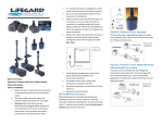
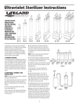
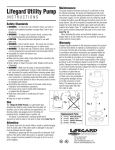
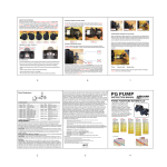
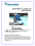
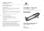
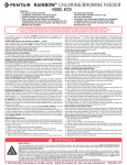
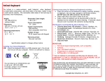
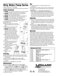
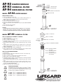
AF-92
AF-93
AF-94
MODEL
HEATER MODULE
CHEMICAL FILTER
HEATER
COUPLING
R175022
GASKET ½" FOR COUPLING
R175023
GASKET ¾" FOR COUPLING
MECHANICAL FILTER
R175021
3" CLEAR HEATER CAP W/COUPLING
AF-92 HEATER MODULE
220001 CAP O-RING
HEATER INSTALLATION
1. Remove coupling from heater cap.
2. If 1" diameter heater is to be used, remove smaller rubber gasket, if ¾"
diameter heater is used, use both gaskets (small inside the large).
3. Slide coupling over heater tube.
4. Insert heater through gasket and clear cap.
5. Screw on coupling to clear cap and tighten.
6. Screw clear cap with heater installed onto heater module. HAND TIGHTEN
ONLY.
7. Start water flow through module.
8. Turn on heater and adjust.
CAUTION
AT NO TIME OPERATE HEATER WITHOUT MODULE FULL OF WATER.
DAMAGE WILL RESULT TO BOTH HEATER AND HEATER MODULE
IF HEATER IS OPERATED WHEN DRY. DO NOT LUBRICATE GASKETS.
MODEL
AF-93
R270313 - ¾" CLOSE NIPPLE
R270484 - 1" CLOSE NIPPLE
R172008 - 3" FILTER CAP
CHEMICAL FILTER
HOW TO CHARGE THE CHEMICAL CHAMBER
1.
2.
3.
4.
5.
6.
7.
8.
9.
220001 - CAP O-RING
Unscrew module cap.
Remove cup spring and cartridge plug.
Remove chamber from module.
Fill chamber with coarse granular carbon or other media that will not pass
through the chamber screen.
Rinse carbon by letting water run down chamber through open end until
clear.
Install chamber in filter module. Make sure chamber fits onto center hub in
bottom of filter module. Chamber should protrude about 1/16" above module.
Replace cartridge plug.
Install cup spring, large end over cartridge plug.
Before replacing module cap make sure O-ring is clean, lubricated with
Lifegard Silicone and is in place. HAND TIGHTEN ONLY.
HOW TO CLEAN AND RECHARGE
1.
2.
3.
4.
5.
6.
Shut off pump.
Shut off inlet and outlet valve installed below the level of the module cap.
Remove cap from module.
Remove cup spring, cartridge plug and chamber from module.
Empty carbon or other media from chamber.
Fill chamber with new carbon or other media. Make sure filtering media will
not pass through the chamber screen.
7. Rinse carbon by letting water run down chamber through open end until
clear.
8. Before replacing module cap, remove the O-ring and thoroughly clean it,
and lubricate the O-ring with Lifegard silicone and replace cap on the
module and HAND TIGHTEN ONLY.
9. Open inlet and outlet valve and start pump.
R172014
CARTRIDGE
PLUG
R172043 - CUP SPRING
R175056 - CAP RETAINER CHAMBER
R175029 - RETAINER CHAMBER
AF-93 ONLY
R175054 - RETAINER CHAMBER
AF-93-19 ONLY
R175055 - RETAINER CHAMBER
AF-93-29 ONLY
REDUCER BUSHINGS
AF Modular Series units have option of connection to 3/4" MPT
or 1" MPT using reducer bushings included in package. 11/4" x 3/4",
11/4" x 1", 11/2" x 3/4" or 11/2" x 1". Bushing of your choice should
be glued using a PVC/ABS compatible glue.
R174000
R174001
R174002
R174003
-
1
1 /4" x
11/4" x
11/2" x
11/2" x
3
/4"
1"
3
/4"
1"
Lifegard
Lifegard
Lifegard
Lifegard
Reducer
Reducer
Reducer
Reducer
R270313 - ¾" CLOSE NIPPLE
R270484 - 1" CLOSE NIPPLE
Bushing
Bushing
Bushing
Bushing
www.lifegardaquatics.com
MODEL
AF-94
MECHANICAL FILTER
R172045B - PRESSURE GAUGE
HOW TO CHARGE THE COMBINATION AQUARIUM CARTRIDGE
1.
2.
3.
4.
5.
6.
7.
8.
9.
Unscrew module cap.
Remove cup spring and cartridge plug.
Remove cartridge from module.
Fill inner cartridge core with coarse granular carbon or other media that will
not pass through the inner retainer screen.
Rinse carbon by letting water run down through open end of cartridge until clear.
Install cartridge in filter module. Make sure cartridge fits onto center hub in
bottom of filter module. Cartridge should protrude about 1/16" above module.
Replace cartridge plug.
Install cup spring-large end over cartridge plug.
Before replacing module cap make sure O-ring is clean and lubricated with
Lifegard Silicone and in place.
START UP INSTRUCTIONS
1. Thread gauge adapter and air bleed into cap. Gauge adapter is sufficiently
tightened with 1 or 2 threads showing on inside of cap. Over-tightening will
break gauge adapter or interfere with cartridge. Do not over-tighten. FINGER
TIGHTEN ONLY!
2. Open air bleeder beneath the pressure gauge.
3. Begin water flow through module.
4. Close air bleeder when a few drops of water are expelled.
5. To pre-determine the pressure at which to change the filter pleats, shut off
outlet valve so that no water is allowed to flow back to the aquarium, then
record the pressure indicated (maximum pump output). The pleat change
pressure will be one or two psi less than the maximum reading just obtained.
It is recommended that the change pressure be marked with a piece of tape,
as it may be quite some time before this pressure is reached.
R172045A - GAUGE ADAPTER
& AIR BLEED
R172012 - 3" CAP WITH ¼" HOLE
220001 - CAP O-RING
R172043 - CUP SPRING
R172014 - CARTRIDGE PLUG
R175028 - PLEAT RETAINER
R175024 - COMBINATION
CARTRIDGE COMPLETE
SEE BELOW FOR MODELS
AF-94-19 AND AF-94-29
R175026 - PLEAT ONLY
(STANDARD)
R175028 - PLEAT RETAINER
WHEN TO CLEAN THE FILTER
1. When the gauge reaches the change pressure and/or when the water flow
has decreased considerably.
HOW TO CLEAN THE FILTER
1.
2.
3.
4.
5.
6.
7.
8.
Shut off pump.
Shut off inlet and outlet valve installed below the level of the module cap.
Remove cap from module.
Remove cartridge, retainers from pleats, and pleats from cartridge. Carbon or
other media may be changed at this time.
Install new pleats by starting at the bottom of the cartridge and inserting one
pleat into each of the 30 V-shaped sections in the filter cartridge. When the
bottom of the filter pleats are completely seated, simply run your hand up the
filter pleats and the pleats will seat themselves along the entire cartridge.
Make sure the pleat retainers are seated properly.
To re-charge cartridge refer to numbers 1.-9.
Before replacing module caps, remove the O-ring and thoroughly clean it as
well as the O-ring seat and all threads. Coat the O-ring with Lifegard Silicone
and replace cap on the module and HAND TIGHTEN ONLY.
Open inlet and outlet valve, open the bleed valve on the pressure gauge
until a few drops of water are expelled, then close air bleed valve and start
pumping.
Model AF-94-19 and
AF-94-29
do not use the
combination cartridge.
When cleaning,
remove center
stand pipe,
clean and replace
(refer to drawing)
R270313 - ¾" CLOSE NIPPLE
R270484 - 1" CLOSE NIPPLE
MODELS AF-94-19
AF-94-29
ONLY
R175025
AQUARIUM CARTRIDGE
COMPLETE HAS NO CARBON
RETAINER
AF-94-19 (2) REQUIRED
AF-94-29 (3) REQUIRED
WARRANTY POLICY
PLEATS ARE SAME AS MODULE AF-94
Warranty period starts from date of purchase and must be validated with copy of original purchase
receipt.
Warranty requests by phone will not be honored.
Warranty items returned without copy of original purchase receipt will not be honored.
Products purchased from EBay, Craig’s List, etc. cannot be honored for warranty unless returned
by original purchaser with proof of purchase.
CENTER STAND PIPE
R172018 FOR AF-94-19
All items must first be returned to Lifegard Aquatics for inspection, evaluation, and processing to
determine if product qualified for warranty replacement or repair. No warranty (repair, replacement,
or credit) will be issued prior to inspection of products. Please contact us first for warranty
assistance. Many times the product can be repaired without the cost and time involved in
sending it back to us. If absolutely necessary, return product freight prepaid to the following
address for warranty evaluation and processing.
R172017 FOR AF-94-29
One year warranty on all Lifegard Modules.
Lifegard Aquatics, 13911 Struikman Road, Cerritos, CA 90703.
Tel (562) 404-4129 • Fax (562) 404-4159 • Email: [email protected]
To
Aquarium
www.lifegardaquatics.com
e
Quiet One
Pump
Mechanical
Filter
Chemical
Filter
F
Heater
Module
Ultraviolet
Sterilizer
COMPLETE
MODULAR
SYSTEM