1
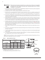
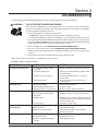
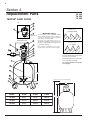
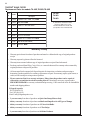
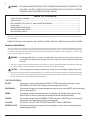
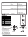
® Tarpon Sand Filter Models: TA 40D, TA 50D, TA 60D Installation and User's Guide IMPORTANT SAFETY INSTRUCTIONS READ AND FOLLOW ALL INSTRUCTIONS SAVE THESE INSTRUCTIONS Table of Contents Important Warning and Safety Instructions ......................................................................... ii Section 1: Installation ....................................................................................................... 1 Installing the Sand Filter .......................................................................................... 1 How your Filter works ............................................................................................. 1 Initial Start-Up .......................................................................................................... 3 Section 2: Maintenance ..................................................................................................... 4 Filter Care ................................................................................................................ 4 Filter Cleaning .......................................................................................................... 4 Filter Backwash Procedure ..................................................................................... 5 Chemical Cleaning Procedure ................................................................................. 5 Winterizing your Filter .............................................................................................. 6 Section 5: Troubleshooting .............................................................................................. 7 Section 4: Replacement Parts .......................................................................................... 8 Six Way Valve (1- 1/2") Installation, Operation & Service Manual © 2012 Lifegard Aquatics Inc. All rights reserved. Tel: (562) 404-4129 FAX (562) 404-4159 Email: [email protected] - visit www.lifegardaquatics.com Tarpon® is a registered trademark of Lifegard Aquatics Inc. and/or its affiliated companies in the United States and/or other countries. P/N 151016 Rev. A 3/20/12 i IMPORTANT WARNING AND SAFETY INSTRUCTIONS Important Notice: This guide provides installation and operation instructions for the Tarpon® Sand Filters. Attention Installer: This guide contains important information about the installation, operation and safe usage of this product. This information should be given to the owner and/or operator of this equipment after installation or left on or near the filter. Attention User: This manual contains important information that will help you in operating and maintaining this filter. Please retain it for future reference. WARNING — Before installing this product, read and follow all warning notices and instructions which are included. Failure to follow safety warnings and instructions can result in severe injury, death, or property damage. Consumer Information and Safety The Sand Filters are designed and manufactured to provide many years of safe and reliable service when installed, operated and maintained according to the information in this manual and the installation codes referred to in later sections. Throughout the manual, safety warnings and cautions are identified by the “ “ symbol. Be sure to read and comply with all of the warnings and cautions. WARNING — THIS FILTER OPERATES UNDER HIGH PRESSURE When any part of the circulating system, (e.g., closure, pump, filter, valve(s), etc.), is serviced, air can enter the system and become pressurized. Pressurized air can cause the top closure to separate which can result in severe injury, death, or property damage. To avoid this potential hazard, follow these instructions: 1. If you are not familiar with your pool filtering system and/or heater: a. Do NOT attempt to adjust or service without consulting your dealer, or a qualified pool technician. b. Read the entire Installation & User’s Guide before attempting to use, service or adjust the pool filtering system or heater. 2. Before repositioning valve(s) and before beginning the assembly, disassembly, or any other service of the circulating system: (A) Turn the pump OFF and shut OFF any automatic controls to ensure the system is NOT inadvertently started during the servicing; (B) open the manual air bleeder valve; (C) stand clear of filter; (D) wait until all pressure is relieved. 3. Whenever installing the filter closure FOLLOW THE FILTER CLOSURE WARNINGS EXACTLY. 4. Once service on the circulating system is complete FOLLOW INITIAL START-UP INSTRUCTIONS EXACTLY. 5. Maintain circulation system properly. Replace worn or damaged parts immediately, (e.g., closure, pressure gauge, valve(s), o-rings, etc). 6. Be sure that the filter is properly mounted and positioned according to instructions provided. Tarpon® Sand Filter Installation and User’s Guide ii IMPORTANT WARNING AND SAFETY INSTRUCTIONS (continued) WARNING — This filter must be installed by a licensed or certified electrician or a qualified pool serviceman in accordance with the National Electrical Code and all applicable local codes and ordinances. Improper installation could result in death or serious injury to pool users, installers, or others and may also cause damage to property. Always disconnect power to the pool circulating system at the circuit breaker before servicing the filter. Ensure that the disconnected circuit is locked out or properly tagged so that it cannot be switched on while you are working on the filter. Failure to do so could result in serious injury or death to serviceman, pool users or others due to electric shock. WARNING — Do not operate the filter until you have read and understand clearly all the operating instructions and warning messages for all equipment that is a part of the pool circulating system. The following instructions are intended as a guide for initially operating the filter in a general pool installation. Failure to follow all operating instructions and warning messages can result in property damage or severe personal injury or death. WARNING — To reduce the risk of injury, do not permit children to use this product unless they are closely supervised at all times. WARNING — Due to the potential risk that can be involved it is recommended that the pressure test be kept to the minimum time required by the local code. Do not allow people to work around the system when the circulation system is under pressure test. Post appropriate warning signs and establish a barrier around the pressurized equipment. If the equipment is located in an equipment room, lock the door and post a warning sign. Never attempt to adjust any closures or lids or attempt to remove or tighten bolts when the system is pressurized. These actions can cause the closure to blow off and could cause severe personal injury or death if they were to strike a person. WARNING — Never exceed the maximum operating pressure of the system components. Exceeding these limits could result in a component failing under pressure. This instantaneous release of energy can cause the closure to blow off and could cause severe personal injury or death if they were to strike a person. Tarpon® Sand Filter Installation and User’s Guide 1 Section 1 Installation Note: Before installing this product, read and follow all warning notices and instructions in this manual. Installing the Tarpon® Sand Filter Only a qualified service person should install the Sand Filter. This filter is designed and intended for use to filter water. Introduction The following general information describes how to install the Sand Filter. This filter operates under pressure and if assembled improperly or operated with air in the water circulation system, it can separate and result in an accident causing property damage or serious bodily injury. A warning label has been affixed to the top of the filter and should not be removed. Keep safety labels in good condition and replace if missing or illegible. How your sand filter works Your high rate sand filter is designed to operate for years with a minimum of maintenance and when installed, operated and maintained in accordance with these instructions, it will provide years of trouble free operation. Dirt is collected in the filter as the water flows through the control valve at the top of the filter and is directed downward onto the top surface of the filter sand bed. The dirt is collected in the sand bed and the clean water flows through the lower piping at the bottom of the filter up through the center pipe into the control valve at the top of the filter. Clean water then returns through the piping system into the pool. The pressure will rise and the flow to the pool will be lowered as the dirt is collected in the filter. Eventually, the filter will become so plugged with dirt that it will be necessary to perform the backwash procedure. It is important to know when to backwash the filter. Backwashing is discussed further under the subsequent sections of this guide. Please note that a filter removes suspended matter and does not sanitize the pool. The pool water must be sanitized and the water must be chemically balanced for sparkling clear water. Your filtration system should be designed to meet your local health codes. As a minimum, you must be sure that your system will turn over the total volume of water in your pool at least twice in a twenty-four hour period. Refer to Table 1 for Filter Operation Data. Table 1. FILTER MODEL NUMBER FILTER AREA (Sq. Ft.) TURNOVER CAPACITY (Gallons) FLOW RATE *(GPM) 4 TURNS PER DAY 3 TURNS PER DAY 2.4 TURNS PER DAY 2 TURNS PER DAY TA 40D 1.8 40 14,400 19,200 24,000 28,800 TA 50D 2.3 50 18,000 24,000 30,000 36,000 TA 60D 3.1 60 21,600 28,800 36,000 43,200 WARNING — Failure to operate your filter system or inadequate filtration can cause poor water clarity obstructing visibility in your pool and can allow diving into or on top of obscured objects which can cause serious personal injury or drowning. Clear water is the result of proper filtration as well as proper water chemistry. Pool chemistry is a specialized area and you should consult your local pool service specialist for specific details. In general, proper pool sanitation requires a free chlorine level of 1 to 2 PPM and a pH range of 7.2 to 7.6. Tarpon® Sand Filter Installation and User’s Guide 2 WARNING — Filters should never be tested or subjected to air or gas under pressure. All gases are compressible and under pressure create a danger. Severe bodily injury or property damage could occur if the filter is subjected to air or gas pressure. 1. Check carton for any evidence of damage due to rough handling in shipment. If carton or any filter components are damaged, notify the freight carrier immediately. 2. Carefully remove the accessory package and the filter tank from the carton. 3. Mount the filter on a permanent slab, preferably concrete poured in a form or on a platform constructed of concrete block or brick. DO NOT use sand to level the filter or for the pump mounting, as it will wash away. 4. Provide space and lighting for routine maintenance access. Do not mount electrical controls over the filter. One needs to be able to stand clear of the filter when starting the pump. Minimum space requirements may be found on the large nameplate on the filter. 5. Sand specifications – be certain the proper sand is used as described in Table 2. Before pouring the sand into the filter, look inside and check the lower under-drain for broken or loose laterals (or fingers), which may have been accidentally damaged by rough handling during shipment. Replace any broken parts if necessary. 6. Install the sand guide in the top of the filter and fill the tank about half full with water. Pour the sand into the top of the filter at a slow rate so that the weight of the sand does not damage the laterals. See Table 2 for proper amounts of sand. After filling to the proper level, remove and discard the sand guide. Wash away all sand around the opening at the top of the tank. 7. Be sure that all sealing surfaces are clean and apply a light coating of a silicone based lubricant to the valve o-ring. 8. Position valve so that the port locations are in the desired final positions. Follow the enclosed valve installation procedure instructions. 9. Assemble piping and pipe fittings to pump and valve. All piping must conform to local and state plumbing and sanitary needs. 10. Use sealant compounds on all male connections of pipe and fittings. Use only pipe compounds suited for plastic pipe. Support pipe to prevent strains on filter, pump or valve. NOTE: The free board distance is the most important variable and should be maintained. Sand density will vary and therefore sand amount is given as a reference. Table 2. Filter Sand Detail and Data "X" FREE BOARD FILTER MEDIA (POUNDS) FILTER MODEL ALL SAND* PEA GRAVEL ‡ SAND FREE BOARD "X" TA 40D 175 50 125 7¾" TA 50D 225 50 175 9¼" TA 60D 325 50 275 10¼" ALL SAND or SAND & GRAVEL ‡ Pea Gravel size to be 1/8” to 1/4” diameter. * SAND SIZE: .018 - .022 in. particle size (.44-.55 mm particle size) = No. 20 Standard Silica Sand having a uniformity coefficient of 1.75 or less. Sand Guide Tarpon® Sand Filter Installation and User’s Guide 3 11. Long piping runs and elbows restrict flow. For best efficiency, use the fewest possible number of fittings, large diameter pipe (at least 1½” for TA 60) and locate equipment as close to pool as possible. CAUTION —Operating at excessive vacuum levels can cause the tank to crack and could cause property damage. 12. When installing backwash lines it is recommended that a vacuum breaker, (P/N 272044), be installed on installations where the backwash line is 1½” and the length exceeds 40 ft., or if the backwash line discharges 10 ft. or more lower than the surface level of the pool. Alternately, a vacuum break pit could be provided on systems using 2” or larger backwash lines. 13. A check valve is recommended between the filter and heater to prevent hot water “back up” which will damage the filter and valve. 14. The maximum operating pressure of this unit is 50 pounds per square inch. Never operate this filter above this pressure or attach a pump to this filter that has more than 50 psi shut-off pressure. 15. A positive shut-off valve is not recommended at the outlet of the filtering system. If the system is ever run with such a valve closed, the internal air relief system becomes inoperative and an explosive situation could exist. Additionally, running the system with no flow will seriously damage the equipment. WARNING — Chemical fumes and/or spills can cause severe attack of filter structural components. Structually weakened filter components can cause filter valve or attachments to separate and could cause severe bodily injury and/or property damage. Initial Start-up 1. On a new pool, clean the pool before filling the pool with water. Excessive dirt and large particles can cause damage to the pump and filter. 2. Ensure that the backwash line is open so that water is free to come from the pool and flow out the backwash line. Set control valve to backwash position. 3. Check pump strainer pot to be sure it is full of water. Replace pump lid. WARNING — Air entering the filter and the valve clamp not closed properly can cause the valve to separate and could cause severe bodily injury and/or property damage. 4. Check valve clamp on Tarpon for tightness. 5. Open the manual air bleeder on the 6-Way Valve. Stand clear of the filter and start the pump allowing it to prime. 6. Close the air bleeder on the 6-Way Valve when all the air is removed from the filter and a steady stream of water emerges. NOTE: Pool filter sand is typically pre-washed and should not require extensive backwashing. However, the shipping process may cause excessive abrasion which could require an extended backwash cycle at initial start-up; continue to backwash until the backwash water is as clear as the pool water. CAUTION — To prevent equipment damage and possible injury, always turn the pump off before changing the valve position. 7. 8. 9. 10. 11. Stop the pump. Set the valve to the filter position. Ensure all suction and pool return lines are open so that water is free to come from the pool and return to the pool. Open the manual air bleeder on the 6-Way Valve. Stand clear of the filter and start the pump. Close the air bleeder on the 6-Way Valve, when a steady stream of water emerges. The filter has now started its filtering cycle. You should ensure that water is returning to the pool and take note of the operating pressure when the filter is clean. Tarpon® Sand Filter Installation and User’s Guide 4 Section 2 Maintenance This section describes how to maintain your Sand Filter. Filter Care The filter is a very important part of the pool equipment and installation. Proper care and maintenance will add many years of service and enjoyment to the pool. Follow these suggestions for long trouble-free operation: 1. To clean the exterior of the filter of dust and dirt, wash with a mild detergent and water then hose off. Do not use solvents. 2. If internal maintenance is required, sand may be removed by removing the entire drain spigot from the bottom of the filter and flushing with a garden hose. 3. If, after a number of years, the filter tank appears foggy in color or rough in texture, the tank surface can be painted. We recommend the use of a Quick Dry Spray Enamel. Do NOT paint the VALVE. WARNING — Always visually inspect filter components during normal servicing to ensure structural safety. Replace any item which is corroded, deformed or otherwise visually defective. Defective filter components can allow the filter top or attachments to separate and could cause severe bodily injury or property damage. 4. The valve clamp used on your Sand Filter was manufactured with high quality corrosion resistant materials. The manufacturing process could allow sharp edges to be present on htthe parts. When working around the clamp, use caution to prevent potential injury to fingers or hands from contact with sharp edges. 5. Your filter is a pressure vessel and should never be serviced while under pressure. Always relieve tank pressure and open air bleeder on the Valve before attempting to service your filter. 6. When restarting your filter, always open the manual air bleeder on the Valve and stand clear of the filter. Cleaning Frequency 1. The filter on a new pool should be backwashed, and cleaned after approximately 48 hours of operation to clean out plaster dust and/or construction debris. 2. There are three different ways to identify when the filter needs backwashing. a. The most accurate indicator on pool systems with a flow meter is to backwash when the flow decreases 30% from the original (clean filter) flow. For example, if the original flow was 60 GPM, the filter should be backwashed when the flow is reduced by about 20 GPM (or 30%) to 40 GPM. b. A more subjective and less accurate indicator is to observe the amount of water flowing from the flow directionals located in the wall of the pool. The filter should be backwashed once it is detected that the flow has been reduced. c. The most commonly used but less accurate indicator is to backwash when the filter gauge reading increases 10 PSI over the initial (clean filter) reading. 3. It is important not to backwash the filter solely on a timed basis such as every three days. It is also important to note that backwashing too frequently actually causes poor filtration. Factors like weather conditions, heavy rains, dust or pollen, and water temperatures all affect the frequency of backwash. As you use your pool, you will become aware of these influences. 4. If, at any time, the starting pressure after backwashing the filter indicates 4 to 6 PSI higher than normal starting pressure, it is time to perform a chemical cleaning procedure. Tarpon® Sand Filter Installation and User’s Guide 5 Filter Backwash Procedure WARNING —To prevent equipment damage and possible injury, always turn off pump before changing valve positions. 1. Stop the pump. 2. Ensure that the suction and backwash lines are open so that water is free to come from the pool and flow out the backwash line. Set control valve to backwash position. 3. Stand clear of the filter and start the pump. 4. Backwash filter for approximately 3 to 5 minutes or until backwash water is clean. 5. Stop the pump and set valve to rinse position. 6. Stand clear of the filter and start the pump. 7. Rinse filter for approximately 30 seconds. 8. Stop the pump and set valve to filter position. 9. Ensure that pool return line is open so that water may flow freely from the pool back to the pool. 10. Open manual air bleeder on 6-Way Valve. Stand clear of filter and start the pump. 11. Close manual air bleeder on the 6-Way Valve, when all the air is removed and a steady stream of water emerges from the bleeder. 12. The filter has now started its filtering cycle. You should ensure that water is returning to the pool and take note of the filter pressure. 13. The filter pressure, in the above Step 12, should not exceed the pressure originally observed on the filter when it was initially started. If after backwashing, the pressure is 4 to 6 PSI above the start condition, it will be necessary to chemically clean the sand bed. Chemical Cleaning Procedure 1. It is recommended that an approved cleaner be used. Please contact your local pool chemical supplier or retailstore for the proper cleaner. These cleaners will remove oils, scale and rust from the sand bed in one cleaning operation. 2. Mix a solution following the manufacturers instructions on the label. 3. Backwash the filter with the Multiport Valve as outlined above. 4. If the filter is below pool level, shut off the pump and close appropriate valving to prevent draining the pool. 5. Shut off pump, open filter drain and let filter drain. Place valve in backwash position. 6. After filter has drained, close filter drain and remove the pump strainer pot lid. 7. Ensure that the backwash lines are open. 8. Turn the pump on and slowly, pour the cleaning solution into the pump strainer with the pump running. If the filter is below pool, open shut-off valve slightly to allow pump to run. 9. Continue adding solution until the sand bed is saturated with cleaning solution. 10. Shut off the pump and leave filter in backwash position. Allow filter to stand overnight (12 hours). 11. Replace the pump lid and follow backwash procedures as outlined above. 12. Do not allow the cleaning solution to get into the pool. Tarpon® Sand Filter Installation and User’s Guide 6 Winterizing your Filter 1. In areas that have freezing winter temperatures, protect the pool equipment by backwashing the filter. 2. After backwashing, shut the pump off, open the manual air bleeder on the 6-Way Valve, and move the handle of the Multiport Valve to the Winterize Position. 3. Remove the wing-type plug on the bottom of the filter. The filter will drain very slowly, and therefore, it is recommended that the drain plug be left out during shutdown season. *NOTE: The Multiport Valve should be left in the “Winterize Position” during shutdown season so that the valve diverter has no pressure on the rubber seal. 4. Drain all appropriate system piping. 5. We recommend covering the equipment with a tarpaulin or plastic sheet to inhibit deterioration from weather. Do NOT wrap the pump motor with plastic. Tarpon® Sand Filter Installation and User’s Guide 7 Section 3 Troubleshooting Use the following troubleshooting information to resolve possible problems with your Sand Filter. WARNING — THIS FILTER OPERATES UNDER HIGH PRESSURE When any part of the circulating system, (e.g., closure, pump, filter, valve(s), etc.), is serviced, air can enter the system and become pressurized. Pressurized air can cause the top closure to separate which can result in severe injury, death, or property damage. To avoid this potential hazard, follow these instructions: 1. If you are not familiar with your pool filtering system and/or heater: a. Do NOT attempt to adjust or service without consulting your dealer, or a qualified pool technician. b. Read the entire Installation & User’s Guide before attempting to use, service or adjust the pool filtering system or heater. 2. Before repositioning valve(s) and before beginning the assembly, disassembly, or any other service of the circulating system: (A) Turn the pump OFF and shut OFF any automatic controls to ensure the system is NOT inadvertently started during the servicing; (B) open the manual air bleeder valve; (C) wait until all pressure is relieved. 3. Whenever installing the filter closure FOLLOW THE FILTER CLOSURE WARNINGS EXACTLY. 4. Once service on the circulating system is complete FOLLOW INITIAL START-UP INSTRUCTIONS EXACTLY. 5. Maintain circulation system properly. Replace worn or damaged parts immediately, (e.g., closure, pressure gauge, valve(s), o-rings, etc). 6. Be sure that the filter is properly mounted and positioned according to instructions provided. Note: Turn off power to unit prior to attempting service or repair. Problems and Corrective Actions PROBLEM CAUSE REMEDY Pool water not sufficiently clean 1. Pool chemistry not adequate to inhibit algae growth. 2. Too frequent a backwash cycle. Maintain pool chemistry or consult pool service technician. 3. Improper amount or wrong sand size. 4. Inadequate turnover rate. Allow pressure to build to 10 psi above clean filter condition before backwashing. Check sand bed depth and sand size or consult a pool service technician. Run system for longer time or consult dealer or pool service technician. High filter pressure 1. Insufficient backwashing. 2. Sand bed plugged with mineral deposits. 3. Partially closed valve or restriction in return. Backwash until effluent runs clear. Chemically clean filter. Open valve or remove obstruction in return line. Short cycles 1. Improper backwash. 2. Pool chemistry not adequate to inhibit algae growth. 3. Plugged sand bed. Backwash until effluent runs clear. Maintain pool chemistry or consult pool service technician. 4. Flow rate too high. Manually remove top 1” surface of sand bed, replace with new sand and chemically clean entire sand bed as described in the Chemical Cleaning Procedure. Restrict flow to capacity of filter. Return flow to pool diminished, low filter pressure 1. Obstruction in pump hair and lint strainer. 2. Obstruction in pump. 3. Obstruction in suction line to pump. Clean basket in pump strainer. Disassemble and clean pump. Clean skimmer basket. Remove obstruction in lines. Open valves in suction line. Sand returning to pool 1. Broken under drain lateral. 2. Backwash rate too high. 3. Air strainer on Tarpon Valve is damaged or missing. Replace broken or damaged laterals. Reduce backwash flow rate. Replace damage components. Tarpon® Sand Filter Installation and User’s Guide 8 Section 4 Replacement Parts TA 40D TA 50D TA 60D TARPON® SAND FILTER TAGELUS (Threaded Style Valve) 17 1B 2B 5 DETAIL A After Dec. 1, 1991 6" BUTTRESS THREAD IMPORTANT NOTICE 3B (See Note 1) The valve adaptor used on TA 40D, 50D, and 60D filters manufactured after November 1, 1994 has a new face seal design with a square sealing ring that is white in color, P/N 154494. TAGELUS DELUXE (Clamp Style Valve) The black o-ring, P/N 154493, used on our TA 40D, 50D, and 60D filters manufactured before November 1, 1994 will NOT interchange with the new 154494 sealing ring. 1A 17 5 2A DETAIL B Before Dec. 1, 1991 6" "V" THREAD When ordering a replacement seal, be sure to specifiy which seal your filter has in the adaptor. 3A 16 4 6 Filters manufactured after Dec 1, 1991 utilize a 6 in. buttress thread in the filter tank top opening and on the closure, see Detail A. 7 Filters manufactured before Dec 1, 1991 utilize a 6 in. “V” type thread, see Detail B. 9 6 in. closures in Detail A. and B. are NOT interchangeable. 10 11 DIM. D 13 14 Clearance to remove valve & internal piping 15 C 12 8 MODEL A DIM. B DIM. C DIM. TA 40D 47 in. 37 in. 19½ in. TA 50D 51½ in. 39½ in. 21½ in. TA 60D 57 in. 42½ in. 24½ in. Tarpon® Sand Filter Installation and User’s Guide A B 9 ® TARPON SAND FILTER Replacement Parts NOTE 1: Item 3A O-ring - Standpipe is used on model TA100D Filters only. Item 3B O-ring - Standpipe is used on Tarpon Filter models TA30, 40, 50, 60 manufactured before April, 1993. Item 3B is not used on Tarpon Clamp Filter models TA30D, 35D, 40D, 50D, 60D or on any Tarpon models manufactured after April, 1993. TARPON FILTERS WITH THD. & CLAMP VALVES Item No. Part No. 1A 262506 VALVE 1½ in. 6-WAY CLAMP STYLE 1B 261130 VALVE 1½ in. 6-WAY BUTTRESS THREAD TA (NOTE 5) 1B 261124 VALVE 1½ in. 6-WAY "V" THREAD-TA (NOTE 6) 2A 272541 O-RING VALVE BODY 3/16 in. X 4¾ in. I.D. 3B 155064 O-RING STANDPIPE 1/8 in. X 1-7/8 in. I.D. (NOTE 1) NOTE 5: Tarpon Filter models TA30, 35, 40, 50, 60 manufactured after Nov. 1, 1991 were manufactured w/ a btr. thread top opening and utilize a btr. style valve which is black in color. A change was made to the port arrangement in April, 1993 which will require that minor changes be made to the valve plumbing connections when replacing valves on filters manufactured between Nov. ‘91 and Mar. ‘93. DO NOT ATTEMPT TO INTERCHANGE THREAD TYPES. 4 152165 CLAMP 6½ in. DIA. S/S, PLASTIC 5 190059 GAUGE BACK MOUNT PRESSURE 6 154555 ADAPTER 6 in. BUTTRESS THD. (NOTES 4 & 7) 6 155225 ADAPTER 6 in. "V" THREAD (NOTES 4 & 8) 6 154521 ADAPTER 8½ in. btr. THREAD (NOTE 4 & 9) NOTE 6: Tarpon Filter models TA30, 40, 50, 60 manufactured before Nov. 1, 1991 were manufactured w/ a “V” thread style valve that is white or brown in color. These valves may be replaced only w/ “V” thread style valve P/N 261124, see Detail B. DO NOT ATTEMPT TO INTERCHANGE THREAD TYPES. 7 154494 O-RING VALVE ADAPTER .157 in. X 5.75 in. I.D. 8 155002 STABILIZER, CENTER PIPE 9 155276 TANK & FT. ASSY. w/ VALVE ADAPTER (NOTES 2, 7 & 8) NOTE 7: Tarpon Clamp Filter models TA30D, 35D, 40D, 50D, 60D manufactured after Nov. 1, 1991 were manufactured w/ a btr. thread top opening and utilize a btr. thread valve adptr. P/N 154555, see Detail A. DO NOT ATTEMPT TO INTERCHANGE THREAD TYPES. 9 155279 TANK & FT. ASSY. w/ VALVE ADAPTER (NOTES 2, 7 & 8) 9 155269 TANK & FT. ASSY. w/ VALVE ADAPTER (NOTES 2, 7 & 8) 9 155342 TANK & FT. ASSY. BUTTRESS THREAD STYLE (NOTES 5 & 6) NOTE 8: Tarpon Clamp Filter models TA30D, 40D, 50D, 60D manufactured before Nov. 1, 1991 were manufactured w/ a “V” thread top opening and utilize a “V” thread valve adptr. P/N 155225, see Detail B). DO NOT ATTEMPT TO INTERCHANGE THREAD TYPES. 9 155343 TANK & FT. ASSY. BUTTRESS THREAD STYLE (NOTES 5 & 6) 9 155358 TANK & FT. ASSY. BUTTRESS THREAD STYLE (NOTES 5 & 6) NOTE 9: Tarpon Filter models TA 100D made before December 1, 1993, have a different threaded operation on the filter tank and require a different 8½” adaptor, P/N 154521. 10 155061 PIPING ASSY. (DIM. D = 17¾ in.) 10 155062 PIPING ASSY. (DIM. D = 19-7/8 in.) 10 155063 PIPING ASSY. (DIM. D = 22-5/8 in.) NOTE 2: Tarpon Clamp Filter models Tank & ft. assy. have valve adptr. (Item 6) factory installed. NOTE 3: Replacement of Tank ft. requires the use of mounting tape. See part number listed. NOTE 4: Lubricate O-ring liberally w/ silicone lubricant and tighten to following spec: TA30D, 35D, 40D, 50D, 60D. Handtight plus ¼ turn min. TA 40D TA 50D TA 60D Description To determine manufacture date, the first 4 digits of the serial number indicate the month and year product was manufactured. Tarpon® Sand Filter Installation and User’s Guide 10 TARPON® SAND FILTER Replacement Parts for models TA 40D, TA 50D, TA 60D TARPON FILTERS WITH THD. & CLAMP VALVES Item No. Part No. 11 152290 LATERAL 6-11/16 in. LONG, 8 req. 12 154926 FOOT TANK 13 154698 SPIGOT ¾ in. NPT SAND DRAIN 13 154685 SPIGOT ½ in. NPT SAND DRAIN 14 192115 O-RING DRAIN PLUG 1/16 in. X ½ in. I.D. 15 357161 PLUG ¼ in. NPT DRAIN 16 154512 WRENCH 6½ in. ACROSS FLATS 155051 SAND GUIDE (NOT SHOWN) 155281 HUB ASSY. Description TA 40D TA 50D TA 60D To determine manufacture date, the first 4 digits of the serial number indicate the month and year product was manufactured. Warranty Policy • Warranty period starts from date of purchase and must be validated with copy of original purchase receipt. • Warranty requests by phone will not be honored. • Warranty items returned without copy of original purchase receipt will not be honored. • Products purchased from EBay, Craig’s List, etc. cannot be honored for warranty unless returned by original purchaser with proof of purchase. • All items must first be returned to Lifegard Aquatics for inspection, evaluation, and processing to determine if product qualifies for warranty replacement or repair. No warranty (repair, replacement, or credit) will be issued prior to inspection of product. • Please contact us first for warranty assistance. Many times the product can be repaired without the cost and time involved in sending it back. If absolutely necessary, return product FREIGHT PREPAID for warranty evaluation and processing. Call or email our office to obtain RMA number and shipping address. Lifegard Aquatics Tel (562)404-4129 Fax (562)404-4159 Email: [email protected] • 3 year warranty from date of purchase on Quiet One Pump Motors Only. • 60 day warranty from date of purchase on Shafts and Impellers for All Types of Pumps. • 60 day warranty from date of purchase on all Ultraviolet Bulbs. • 60 day warranty from date of purchase on all Test Strips. • 1 year warranty from date of purchase on All Other Products. Tarpon® Sand Filter Installation and User’s Guide 1 6-Way Valve (1-1/2") Installation, Operation & Service Manual IMPORTANT SAFETY INSTRUCTIONS READ AND FOLLOW ALL INSTRUCTIONS SAVE THESE INSTRUCTIONS 6-Way Valve (1-1/2") Installation and User’s Guide 2 WARNING — THIS MANUAL CONTAINS CRITICAL SAFETY INFORMATION WHICH MUST BE FURNISHED TO THE END USER. FAILURE TO READ AND FOLLOW INSTRUCTIONS COULD RESULT IN SERIOUS PERSONAL INJURY AND/OR MAJOR PROPERTY DAMAGE. TABLE OF CONTENTS HOW YOUR VALVE WORKS ..................................................................................................................... INSTALLATION ........................................................................................................................................... REPLACEMENT OF VALVE TOP AND DIVERTER ASSEMBLY ............................................................. VALVE CARE ............................................................................................................................................. WINTERIZING PROCEDURE .................................................................................................................... TROUBLESHOOTING GUIDE ................................................................................................................... REPLACEMENT PARTS ............................................................................................................................ 2 3 4 4 4 5 6 This valve operates under pressure. When closed properly and operated without air in the water system. This valve will operate in a safe manner. CAREFULLY READ AND FOLLOW ALL SAFETY INSTRUCTIONS IN THIS MANUAL OR ON FILTER. How Your Valve Works The six position valve is designed to provide all the necessary positions required to operate, maintain, troubleshoot and service your filter. It is provided with six operating positions and one Winterize position. The valve is constructed of high quality corrosion resistant materials and when installed, operated, and maintained in accordance to these instructions, your valve will provide years of trouble free operation. WARNING — Air entering the filter and a valve clamp not closed properly can cause the valve to blow off and could cause severe bodily injury and/or property damage. (Some valve models do not have a clamp but thread into the filter tank.) 1. This valve is equipped with an external air bleeder device (Item 12). Always open this air bleeder and stand clear of filter and valve before starting system pump and leave open until a steady stream of water is expelled. CAUTION — To prevent equipment damage and possible injury, always turn pump off before changing valve position. 2. This valve has a closed position. The pump should never be on when the valve is in the closed position. If the pump is operated with the valve closed, the air relief system becomes inoperative and an explosive situation could exist. Additionally, running the system with no flow will seriously damage the equipment. VALVE POSITIONS: FILTER - From pump, through valve downward THRU FILTER up through center pipe to valve RETURN port for normal filter action and vacuuming pool thru filter. BACKWASH - From pump through valve, down through center pipe and to valve WASTE port for cleaning filter by reversing flow. RINSE - From pump, through valve downward up through filter up through center pipe to valve WASTE port for start-up cleaning and resetting filter bed after backwashing. WASTE - From pump through valve BYPASSES FILTER and goes to WASTE port for vacuuming directly to waste, lowering pool level, or draining pool. CLOSED - NO FLOW - DO NOT USE THIS SETTING WITH PUMP OPERATING. RECIRCULATE - From pump, through valve, bypasses filter and goes to return port for circulating water without going thru filter. 6-Way Valve (1-1/2") Installation and User’s Guide 3 Installation 1. Check carton for any evidence of damage due to rough handling in shipment or any valve components are damaged, notify freight carrier immediately. NOTICE: When working in and around the clamp use caution to prevent potential injury to fingers or hands from sudden contact with sharp edges. 2. After inspection, carefully remove valve components from carton. Be sure sand has been placed into filter, sand guide has been removed and top of filter cleaned of any sand or debris. NOTE: The filter valve will attach to the filter in one of two ways depending upon the filter and valve type. Clamp style valves utilize a clamp which holds together the flanges of the valve and filter. Follow exactly, steps 3 - 8 below to attach the valve to the filter. (Disregard steps 9 - 12.) 3. Check to be sure (Item 14) o-ring is in place in groove on valve body. Note: Item numbers in this portion of the instructions refer to the replacement parts list on page 5. 4. Open clamp (Item 15) wide enough to place over the flange on the tank and rest on the tank before the valve is installed. 5. Place valve over opening in top of tank so that filter center pipe slips into bore of valve body. 6. Valve parts are labeled with the location of where they should be connected, (i.e. pump port must go to pump discharge, waste port must go to the waste line and return port must go to the pool return). 7. Orient the valve to allow the ports to be plumbed to the proper location. 8. Press down on valve so that (Item 14) o-ring is down inside of opening of tank top. WARNING — Improper tank valve assembly could cause the valve to blow off and cause severe injury and/or property damage. Lift the clamp (Item 15) over the tank flange and carefully guide the clamp so that it catches both the valve flange and the tank flange. Tighten “T’ bolt nut securely. Threaded style valves utilize a large six inch buttress thread that screws directly to the filter tank. Follow exactly, steps 9 - 12 below to attach the valve to the filter. (Disregard steps 3 - 8.) 9. Check to be sure o-ring, (Item 14), is in place above large thread on valve body and that o-ring is lubricated. If o-ring requires lubrication, use only silicone type lubrication. WARNING — Use of lubricants or pipe sealants other than recommended in this instruction booklet, can damage the valve and cause the valve to blow off and could cause severe bodily injury or property damage. 10. Check to be sure filter piping assembly is exactly centered about 1½” below the large threaded opening in the tank. 11. Carefully install the valve inside the filter opening so that the filter piping assembly slips into socket of the valve. Slowly turn valve clockwise until the thread engages with the thread on the tank. Continue to turn valve until the o-ring on valve contacts the tank. Grasp valve by the two opposing ports and tighten as secure as possible by hand. WARNING — Do not install pipes into the threaded ports, for the purpose of gaining mechanical advantage, as this can over tighten and damage the valve and can cause the valve to blow off resulting in severe bodily injury and/ or property damage. NOTE: The valve should not become hard to turn when installing in the filter opening until the valve o-ring contacts the filter surface. Failure to position the filter piping assembly in the center of the large filter opening can cause the valve to not thread properly into the filter tank. 12. Orient the filter with valve to allow the ports to be plumbed to the proper location. 13. The Maximum operating pressure of this valve is 50 psi. The filter unit also has a maximum operating pressure listed on the filter nameplate. DO NOT OPERATE this unit above the maximum operating pressure of the valve or the filter. Never connect the filter and valve unit to a pump which can generate a pressure that exceeds the operating pressure of the filter or valve. 14. Assemble piping and pipe fittings to pump and valve. All piping must conform to local and state plumbing and sanitary codes. 15. Use sealant on all tapered male connections of pipe and fittings. Use only sealant compounds suited for plastic pipe. Support pipe to prevent strains on filter, pump or valve. NOTICE: All valve internal threads are tapered except the air bleeder connection. Do not overtighten tapered thread connections. 16. Install pressure gage in 1/4" NPT port directly across from the pump port. 6-Way Valve (1-1/2") Installation and User’s Guide 4 17. Never store pool chemicals within 10 feet of your pool filter valve. Pool chemicals should always be stored in a cool, dry, well ventilated area. WARNING — Chemical fumes and/or spills can cause severe attack of filter valve structural components. Structurally weakened components can cause filter valve or attachments to blow off and could cause severe bodily injury and or property damage. Replacement of Valve Top and Diverter Assembly 1. Shut off pump and open air bleeder to relieve all internal pressure. 2. Set valve handle to winterize position. 3. Remove six cover screws (Item 9). 4. Lift off valve top and diverter assembly. NOTICE: Valve diverter assembly has the sealing gasket attached to the diverter. When handling the diverter, use caution to prevent the sealing surface from being damaged during handling. 5. Clean valve body sealing surface with soft clean lint free cloth. Inspect surface for damage such as scratches or nicks. If surface is damaged the valve body must be replaced. 6. Carefully lubricate the new valve top replacement o-ring (Item 8) with a silicone based lubricant and place appropriately on valve top. WARNING — Improper tank valve assembly could cause the valve to blow off and cause severe injury and/or property damage. 7. Place the new valve top handle in the winterize position. Install new valve top and diverter assembly making sure small recess on lid and small bump on valve body are aligned. Start all six screws with fingers to ensure that the screw is started in the formed thread of the valve body. Screws should be tightened progressively by tightening diametrically opposite screws and following a crisscross pattern. Tighten all six valve top attachment screws firmly. DO NOT OVER TIGHTEN. NOTICE: Valve top is attached with self-tapping screws. The screws must be aligned properly to prevent cross threading of the screws in the valve body. Valve Care The valve is a very important part of your pool equipment and installation. Proper care and maintenance will add many years of service and enjoyment to the pool. Follow these suggestions for long trouble free operation. 1. To clean the exterior of the valve of dust and dirt, wash with a mild detergent and water and then hose off. Do not use solvents. WARNING — Always visually inspect valve components during normal servicing to ensure structural safety. Replace any item which is corroded, bent or otherwise visually defective. Defective valve components can allow the valve or attachments to blow off and could cause severe bodily injury or property damage. 2. The valve clamp used on your valve has been manufactured with high quality corrosion resistant materials. The manufacturing process could allow sharp edges to be present on the parts. When working in and around the clamp use caution to prevent potential injury to fingers or hands from contact with sharp edges. 3. Your valve is a pressure vessel and should never be serviced while under pressure. Always relieve tank pressure and open air bleeder before attempting to service your valve. 4. Open the manual air bleeder and stand clear of the filter/valve before restarting your pump. Winterizing Procedure 1. Shut off pump and open the valve air bleeder. 2. Drain and winterize the pump and filter per the manufacturer’s instructions. 3. Depress valve handle and rotate so valve pointer is on circular rib on valve top at area on valve marked WINTERIZE. NOTICE: The valve should be left in this position during the shutdown season so the valve diverter has no pressure on the rubber seal. 6-Way Valve (1-1/2") Installation and User’s Guide 5 Troubleshooting Guide Problem Leak to waste port Leakage at port connections to valve Sand returning to pool Cause Remedy 1. Dirt or sand under seal. Remove valve top and clean seal area. 2. Damaged seal. Replace valve top assembly. 3. Damaged valve body in seal area. Replace valve body. 1. Cracked ports. Replace valve body, use proper assembly and do not over tighten port connection. 2. Did not use sealant on threads. Use sealant. 1. Filter problem. Refer to filter manual. 2. Sand blowing through air vent slots or between filter center pipe in valve. Sand size too small or flow rate thru filter too high. Leakage at valve attachment to filter Leakage past o-ring. Remove valve and inspect o-ring & sealing surface. Replace as necessary. Leakage at handle Leakage past o-ring. Replace valve top assembly. Leakage at top of valve to valve body Leakage past o-ring. Remove valve and inspect o-ring & sealing surface, replace as necessary. Leakage at sightglass with vacuum breaker Dirt on sealing gasket. Remove sightglass and rinse with cool water to remove dirt. Replace sightglass if damaged. 6-Way Valve 1 Replacement Parts 2 ITEM P/N 1 2 3 4 5 6 7 8 9 10 11A 11B 12 13 14 15 16 17 18 19 272520 272405 272505 270085 272511 272535 272512 354053 354541 272555 272530 272538 273512 272554 272541 152165 272550 271106 190059 272531 DESCRIPTION 3 HANDLE SCREW - HANDLE WASHER - 1.875" PLASTIC VALVE TOP - W/LABEL O-RING - .75" X 1" X 1/8" SPRING DIVERTER - VALVE W/GASKET O-RING - 3/16" DIA X 5-5/8" ID SCREW - SLOT HEX 10-24 X 1.5 WASHER - 9/16" S/S VALVE BODY - W/DIFFUSER CLAMP STYLE VALVE BODY - W/DIFFUSER THREADED AIR BLEEDER - W/O-RING NUT - #10-24 SERR. FLANGED S/S O-RING - 4.60" ID x 3/16" DIA. CLAMP ASSY. SIGHTGLASS - W/VACUUM PROTECTOR GASKET - SIGHTGLASS PRESSURE GAGE 1½" TOP VALVE ASSY. 9 10 4 5 3 6 7 19 8 11B 11A 18 NOTE: 1. VALVE TOP ASSEMBLY P/N 272531 CONSISTS OF ITEMS 1- 8 AND VALVE INSTRUCTIONS P/N 272517. 16 12 2. VALVES MANUFACTURED BEFORE MARCH 1, 1993, DO NOT CONTAIN ITEM 16 SIGHTGLASS OR ITEM 17 SIGHTGLASS GASKET . 3. CLAMP STYLE VALVES MANUFACTURED BEFORE MARCH 1, 1993, CONTAlN A DIFFERENT AIR BLEEDER WlTH O-RING P/N 272515. THIS PART IS NOT INTERCHANGEABLE WlTH P/N 273512. THREADED VALVES MANUFACTURED BEFORE MARCH 1, 1993, DO NOT CONTAIN AN AIR BLEEDER WlTH O-RING. 17 13 14 18 16 12 17 13 14 SIX INCH BUTTRESS STYLE VALVE 15 CLAMP STYLE VALVE 4. ITEM 8 USED ON VALVES MANUFACTURED AFTER MAY 1, 1992, REPLACES P/N 272401-WASHER AND P/N 272400 SPRING. 6-Way Valve (1-1/2") Installation and User’s Guide 6 Warranty Policy • Warranty period starts from date of purchase and must be validated with copy of original purchase receipt. • Warranty requests by phone will not be honored. • Warranty items returned without copy of original purchase receipt will not be honored. • Products purchased from EBay, Craig’s List, etc. cannot be honored for warranty unless returned by original purchaser with proof of purchase. • All items must first be returned to Lifegard Aquatics for inspection, evaluation, and processing to determine if product qualifies for warranty replacement or repair. No warranty (repair, replacement, or credit) will be issued prior to inspection of product. • Please contact us first for warranty assistance. Many times the product can be repaired without the cost and time involved in sending it back. If absolutely necessary, return product FREIGHT PREPAID for warranty evaluation and processing. Call or email our office to obtain RMA number and shipping address. Lifegard Aquatics Tel (562)404-4129 Fax (562)404-4159 Email: [email protected] • 3 year warranty from date of purchase on Quiet One Pump Motors Only. • 60 day warranty from date of purchase on Shafts and Impellers for All Types of Pumps. • 60 day warranty from date of purchase on all Ultraviolet Bulbs. • 60 day warranty from date of purchase on all Test Strips. • 1 year warranty from date of purchase on All Other Products. © 2012 Lifegard Aquatics Inc. All rights reserved. Tel: (562) 404-4129 FAX (562) 404-4159 Email: [email protected] - visit www.lifegardaquatics.com P/N 151016 Rev. A 3/26/12 6-Way Valve (1-1/2") Installation and User’s Guide


![[ Página intencionalmente en blanco ]](http://vs1.manualzilla.com/store/data/005979389_1-1ee088f8906d2dba9f81cb338c9eb94e-150x150.png)