1
Kinco-K3
User’s Manual
Contents
Part I general introduction ....................................................................................................................................8
Chapter I
System Overview ................................................................................................................................9
1.1 Application Scope of the Product ...................................................................................................................9
1.2 General Designation in the Manual.................................................................................................................9
1.2.1 Vocabulary of Terms.................................................................................................................................9
1.2.2 The Module’s Structure ..........................................................................................................................12
1.3 Denomination Rules for the product .............................................................................................................12
1.3.1 Description of the Product Name...........................................................................................................12
1.3.2 Description of Order Number ................................................................................................................15
1.4 Product list of Kinco-K3 series PLC.............................................................................................................16
Part II hardware manual .....................................................................................................................................20
Chapter I
Application of Kinco-K3 Series Micro PLC...................................................................................21
1.1 Architecture of Kinco-K3 series PLC ...........................................................................................................21
1.1.1 Overview ................................................................................................................................................21
1.1.2 Allowable System Scales ........................................................................................................................22
1.2 DC24V Sensor Supply..................................................................................................................................22
1.3 Interconnection between PLC modules.........................................................................................................24
1.3.1 Overview of the Expansion Bus..............................................................................................................24
1.3.2 Interconnection between PLC Modules..................................................................................................24
1.4 Communicating over a Network ...................................................................................................................25
1.5 Environmental Condition..............................................................................................................................27
Chapter II
CPU Principle and Application......................................................................................................28
1
Kinco-K3
User’s Manual
2.1 Overview ......................................................................................................................................................28
2.1.1 Super Capacitor.....................................................................................................................................28
2.1.2 FRAM (Ferroelectric Nonvolatile Memory)...........................................................................................29
2.1.3 Real-time Clock (RTC)...........................................................................................................................29
2.1.4 Other Functions .....................................................................................................................................30
2.2 Kinco-K3 CPU..............................................................................................................................................30
U
2.3 Structure........................................................................................................................................................31
2.3.1 Front View..............................................................................................................................................31
2.3.2 Operation Switch ...................................................................................................................................31
2.3.3 CPU Status LED ....................................................................................................................................32
2.3.4 Analogue Potentiometer...........................................................................................................................1
2.3.5 I/O Channels on the CPU Module .........................................................................................................33
2.3.5.1 DI (Digital Input) channels .............................................................................................................33
2.3.5.2 DO (Digital Output) Channels ........................................................................................................33
2.3.5.3 Wiring Diagram ..............................................................................................................................35
2.3.6 Expansion Port ......................................................................................................................................36
2.3.7 Communication Port ..............................................................................................................................36
2.4 Advanced Functions......................................................................................................................................37
2.5 Hardware Overview......................................................................................................................................38
2.6 Installation Dimension ..................................................................................................................................39
2.7 Specifications................................................................................................................................................39
2.7.1 CPU Specifications ................................................................................................................................39
2.6.2 DI Specifications....................................................................................................................................40
2.6.3 DC24V Output Specifications ................................................................................................................41
2.6.4 Relay Output Specifications ...................................................................................................................41
Chapter III
DI (Digital Input) Modules ...........................................................................................................43
2
Kinco-K3
User’s Manual
3.1 DI 8*DC24V.................................................................................................................................................43
3.1.1 Main Features ........................................................................................................................................43
3.1.2 Front View..............................................................................................................................................43
3.1.3 Wiring Diagram & Block Diagram ........................................................................................................44
3.1.4 Installation Dimension...........................................................................................................................45
3.1.5 Technical Data .......................................................................................................................................46
3.2 DI 16*DC24V...............................................................................................................................................47
3.2.1 Main Features ........................................................................................................................................47
3.2.2 Front View..............................................................................................................................................47
3.2.3 Wiring Diagram & Block Diagram ........................................................................................................48
3.2.4 Installation Dimension...........................................................................................................................49
3.2.5 Technical Data .......................................................................................................................................50
Chapter IV DO ( Digital Output ) Modules .....................................................................................................51
4.1 DO 8*DC24V ...............................................................................................................................................51
4.1.1 Main Features ........................................................................................................................................51
4.1.2 Front View..............................................................................................................................................52
4.1.3 Wiring Diagram & Block Diagram ........................................................................................................52
4.1.4 Installation Dimension...........................................................................................................................53
4.1.5 Technical Data .......................................................................................................................................54
4.2 DO 8*relay....................................................................................................................................................55
4.2.1 Main Features ........................................................................................................................................55
4.2.2 Front View..............................................................................................................................................55
4.2.3 Wiring Diagram & Block Diagram ........................................................................................................56
4.2.4 Installation Dimension...........................................................................................................................57
4.2.5 Technical Data .......................................................................................................................................58
4.3 DO 16*DC24V .............................................................................................................................................59
3
Kinco-K3
User’s Manual
4.3.1 Main Features ........................................................................................................................................59
4.3.2 Front View..............................................................................................................................................59
4.3.3 Wiring Diagram & Block Diagram ........................................................................................................60
4.3.4 Installation Dimension...........................................................................................................................61
4.3.5 Technical Data .......................................................................................................................................62
4.4 DO 16*Relay ................................................................................................................................................63
4.4.1 Main Features ........................................................................................................................................63
4.4.2 Front View..............................................................................................................................................63
4.4.3 Wiring Diagram & Block Diagram ........................................................................................................64
4.4.4 Installation Dimension...........................................................................................................................65
4.4.5 Technical Data .......................................................................................................................................66
Chapter V DIO, DI/O Modules.........................................................................................................................67
5.1 DIO 8*DC24V..............................................................................................................................................67
5.1.1 Main Features ........................................................................................................................................67
5.1.2 Front View..............................................................................................................................................68
5.1.3 Wiring Diagram & Block Diagram ........................................................................................................69
5.1.4 Installation Dimension...........................................................................................................................70
5.1.5 Technical Data .......................................................................................................................................70
5.2 DI/O, DI4*DC24V
DO4*DC24V..............................................................................................................72
5.2.1 Main Features ........................................................................................................................................72
5.2.2 Front View..............................................................................................................................................72
5.2.3 Wiring Diagram .....................................................................................................................................73
5.2.4 Installation Dimension...........................................................................................................................74
5.2.5 Technical Data .......................................................................................................................................74
5.3 DI/O,
DI 4*DC24V DO 4*Relay............................................................................................................76
5.3.1 Main Features ........................................................................................................................................76
4
Kinco-K3
User’s Manual
5.3.2 Front View..............................................................................................................................................76
5.3.3 Wiring Diagram .....................................................................................................................................77
5.3.4 Installation Dimension...........................................................................................................................78
5.3.5 Technical Data .......................................................................................................................................78
5.4 DI/O, DI 8*DC24V
DO 8*DC24V............................................................................................................80
5.4.1 Main Features ........................................................................................................................................80
5.4.2 Front View..............................................................................................................................................80
5.4.3 Wiring Diagram .....................................................................................................................................81
5.4.4 Installation Dimension...........................................................................................................................82
5.4.5 Technical Data .......................................................................................................................................82
5.5 DI/O, DI 8*DC24V
DO 8*Relay...............................................................................................................84
5.5.1 Main Features ........................................................................................................................................84
5.5.2 Front View..............................................................................................................................................84
5.5.3 Wiring Diagram .....................................................................................................................................85
5.5.4 Installation Dimension...........................................................................................................................86
5.5.5 Technical Data .......................................................................................................................................86
Chapter VI
AI ( Analog input ) Modules .........................................................................................................88
6.1 AI 4*IV, Multi-signal Input ..........................................................................................................................88
6.1.1 Main Features ........................................................................................................................................88
6.1.2 Front View..............................................................................................................................................89
6.1.3 Wiring Diagram .....................................................................................................................................89
6.1.4 Measurement Ranges and The measured value Representation .............................................................91
6.1.5 Installation Dimension...........................................................................................................................91
6.1.6 Technical Data .......................................................................................................................................92
6.2 AI 4*RD, RTD Input ....................................................................................................................................93
6.2.1 Main Features ........................................................................................................................................93
5
Kinco-K3
User’s Manual
6.2.2 Front View..............................................................................................................................................93
6.2.3 Wiring Diagram .....................................................................................................................................94
6.2.4 Measurement Ranges and The measured value Representation .............................................................95
6.2.5 Installation Dimension...........................................................................................................................96
6.2.6 Technical Data .......................................................................................................................................96
6.3 AI 4*Thermistor, thermistor input ................................................................................................................97
6.3.1 Main Features ........................................................................................................................................97
6.3.2 Front View..............................................................................................................................................97
6.3.3 Wiring Diagram .....................................................................................................................................98
6.3.4 Measurement Ranges and The measured value Representation .............................................................99
6.3.5 Installation Dimension...........................................................................................................................99
6.3.6 Technical Data .....................................................................................................................................100
6.4 AI 4*TC, thermocouple Input.....................................................................................................................101
6.4.1 Main Features ......................................................................................................................................101
6.4.2 Front View............................................................................................................................................101
6.4.3 Wiring Diagram ...................................................................................................................................102
6.4.4 Measurement Ranges and The measured value Representation ...........................................................103
6.4.5 Installation Dimension.........................................................................................................................103
6.4.6 Technical Data .....................................................................................................................................104
Chapter VII
AO ( Analog Output ) Modules .................................................................................................105
7.1 AO 2*IV, Multi-signal Output....................................................................................................................105
7.1.1 Main Features ......................................................................................................................................105
7.1.2 Front View............................................................................................................................................106
7.1.3 Wiring Diagram ...................................................................................................................................106
7.1.4 Output Ranges and the Output Value Representation ..........................................................................107
7.1.5 Installation Dimension.........................................................................................................................107
6
Kinco-K3
User’s Manual
7.1.6 Technical Data .....................................................................................................................................108
Chapter VIII
Installation & Wiring Guidelines ............................................................................................109
8.1 Plastic Case Dimension...............................................................................................................................109
8.2 Installaton Guidlines ...................................................................................................................................109
8.2.1 Lengthen the Expansion Bus ................................................................................................................109
8.2.2 Installing the Kinco-K3 modules..........................................................................................................110
8.2.2.1 Panel Mounting.............................................................................................................................110
8.2.2.2 DIN Rail Mounting ....................................................................................................................... 111
8.3 Wiring .........................................................................................................................................................112
8.3.1 CAGE CLAMP Terminal ......................................................................................................................112
8.3.2 Wiring Procedure .................................................................................................................................112
7
Kinco-K3
User’s Manual
Part I
General Introduction
8
Kinco-K3
User’s Manual
Chapter I
System Overview
This chapter will briefly introduce the Kinco-K3 series micro PLC (Programmable Logic Controller) and
focuses on the explanation of the terms related to Kinco-K3 with a purpose of facilitating you to understand the
contents in the following part of this manual. The main content of this chapter covers: application scope of the
product, explanations on relevant terms, rules for nomenclature, etc.
1.1 Application Scope of the Product
According to the accepted classification rules for PLC, Kinco-K3 series PLC falls into the range of micro PLC.
Therefore, it can be used to control machines and small-scale process. Kinco-K3 series PLC can well satisfy the
demands in the following application areas (including but not limited to these applications):
Packing machinery
textile machinery
building material machinery
Foodstuff machinery
plastic machinery
numerical control machine
Printing mechanism
central air conditioner
Environmental Machinery
individual process control device
1.2 General Designation in the Manual
1.2.1 Vocabulary of Terms
▪ Micro PLC (Programmable Logic Controller)
According to the general classification rules, micro PLC generally refers to the type of PLC with the control
points below 128. This type of PLC usually adopts compact structure, that is, a certain number of I/O channels,
output power supply, high-speed output/input and other accessories are integrated on the CPU module.
▪ CPU body
9
Kinco-K3
User’s Manual
Namely, the CPU module, it’s the core of the control system. The user program is stored in the internal storage of
the CPU module after being downloaded through the programming software, and will be executed by the CPU.
Meanwhile, it also executes the CPU self-test diagnostics: checks for proper operation of the CPU, for memory
areas, and for the status of any expansion modules.
▪ Expansion module & expansion bus
The expansion module is used to extend the functions of the CPU body and it is divided into expansion I/O
module (to increase the input/output channels of the system) and expansion functional module (to expend the
functions of CPU).
The expansion bus connects the CPU and expansion modules, and the 16-core flat cable is adopted as the
physical media. The data bus, address bus and the expansion module’s working power supply are integrated into
the expansion bus.
▪ KincoBuilder
The programming software for Kinco-K3 series PLC, accords with IEC61131-3 standard KincoBuilder, presently
provides LD and IL languages for convenience and efficiency in developing the control programs for your
applications. KincoBuilder provides a user-friendly environment to develop and debug the programs needed to
control your applications.
▪ CPU firmware
It is the “operating system” of the CPU module, and is stored in the Flash memory. At power on, it starts
operation to manage and schedule all the tasks of the CPU module.
▪ User program
It’s also called user project or application program, the program written by the user to execute some
specific control functions. After the user program is downloaded to the CPU module, it is stored in
the FRAM. At power on, the CPU module shall read it from FRAM into RAM to execute it.
10
Kinco-K3
User’s Manual
▪ Main program and Scan Cycle
The CPU module executes a series of tasks continuously and cyclically, and we call this cyclical execution of
tasks as scan.
The main program is the execution entry of the user program. In the CPU, the main program is executed once per
scan cycle. Only one main program is allowed in the user program.
▪ Free-protocol communication
The CPU body provides serial communication ports that support the special programming protocol, Modbus RTU
protocol (as a slave) and free protocols. Free-protocol communication mode allows your program to fully control
the communication ports of the CPU. You can use free-protocol communication mode to implement user-defined
communication protocols to communicate with all kinds of intelligent devices. ASCII and binary protocols are
both supported.
▪ I/O Image Area
Including input image area and output image area. At the beginning of a scan cycle, signal status are
transferred from input channels to the input image area; at the end of a scan cycle, the values stored
in the output image area are transferred to output channels;
In order to ensure the consistency of data and to accelerate the program execution, the CPU module only access
the image area during each scan cycle.
▪ Retentive Ranges
Through “Hardware” configuration in KincoBuilder, you can define four retentive ranges to select the areas of
the RAM you want to retain on power loss. In the event that the CPU loses power, the instantaneous data in the
RAM will be maintained by the super capacitor, and ong the retentive ranges will be left unchanged at next
power on. The retaining duration is 72 hours at normal temperature.
11
Kinco-K3
User’s Manual
▪ Data backup
Data backup is the activity that you write some data into E2PROM or FRAM through relevant instruction for
permanent storage. Notice: Every type of permanent memory has its own expected life, for example, E2PROM
allows 100 thousand of times of writing and FRAM provides unlimited read/write endurance.
1.2.2 The Module’s Structure
Diagram 1-1 the Module’s Structure
1.3 Denomination Rules for the product
1.3.1 Description of the Product Name
The “product name” of Kinco-K3 PLC is used to indicate the main functions and application purpose of the
product. The “product name” is not for any individual product but the general term for a type of products. The
“product name” is defined according to the following principle:
Product name: module type + 3 + subtype + serial number
12
Kinco-K3
User’s Manual
▪ Module type is indicated with the following letters
▪3
:
CPU
CPU module
PM
expansion I/O module
FM
expansion function module
SW
Software
AS
Accessory
Stands for Kinco-K3 series micro PLC
▪ Subtype: a one-digit number (0~9) is used to indicate the subtype of the module.
0
CPU module
1
Reserved
2
Digital Input/Output module
3
Analog Input/Output module
4
Communication module
5
Specific function module
6
Software
7
Accessory
8
Reserved
9
Reserved
▪ Serial number: A one-digit number (0~9) is used to indicate the sequence number of a subtype. The serial
numbers of subtypes have the following implications.
▪ CPU module
4 CPU which provides 14 I/O channels on the CPU body;
6 CPU which provides 24 I/O channels on the CPU body;
13
Kinco-K3
User’s Manual
8 CPU which provides 40 I/O channels on the CPU body;
Other serial numbers are reserved.
▪ Digital Input/Output module
1 DI (digital input) module;
2
DO (digital output) module;
3
DI / DO mixed module;
Other serial numbers are reserved.
▪ Analog Input/Output module
1
AI (analog input) module;
2
AO (analog output) module;
3
AI/AO mixed module;
Other serial numbers are retained.
▪ Communication Module
0
RS485 communication module;
2 Profibus-DP slave module;
3
DeviceNet module;
4
Ethernet module;
6 Modem module;
Other serial numbers are reserved.
▪ Special Function Module
0 Motion control module;
Other serial numbers are reserved.
▪ Software
0
Programming software;
Other serial numbers are reserved.
▪ Accessories
0
Programming cable;
14
Kinco-K3
User’s Manual
1
Profibus-DP connector;
2
Profibus-DP Repeater;
Other serial numbers are reserved.
According to the above principle, CPU306 indicates a CPU module with 24 I/O channels; PM321 indicates DI
expansion module; AS360 stands for KincoBuilder programming software, etc.
1.3.2 Description of Order Number
The difference from “product name” is that each product has a unique “order No.”, users are merely required to
expressly inform us the order number of the demanded product when making an order. The “order number” is
confirmed in accordance with the following rule:
Kinco-K + module code + feature code
15
Kinco-K3
User’s Manual
Fixed prefix
Kinco-K
CPU and PM must have this option,
but other modules may omit it
Optional:
Sub-item of function identifier,
Represented with the letters X, Y, Z
Number
same with the
product name
or numbers 0~9
The 1st digit indicates:
Power supply voltage
D: DC 24V
A: AC 85-265V
Number of I/O channels
The 2nd digit indicates:
CPU and
Type of the output channel
Digital Module T: Transistor
R: Relay
Function
identifier
Fill in X where not
applicable
Analog Moudule
IV: current/voltage
TC: thermal couple
RD: RTD
NT: NTC thermistor
Diagram 1-2 Description of the Order Number
According to the above principle, Kinco-K306-24DT stands for the CPU module with 24 I/O channels (wherein
the output channel is of transistor type) and DC24V power supply; Kinco-K321-08DX stands for the DI
expansion module with 8 transistor-type input channels.
1.4 Product list of Kinco-K3 series PLC
16
Kinco-K3
User’s Manual
Type
Name
Order no.
Kinco-K304-14AT
CPU304
Kinco-K304-14AR
Description
AC85~265V power supply, with 14 I/O, DI 8*DC24V, DO
6*DC24V, max output current per channel 0.75A
AC85~265V power supply, with 14 I/O, DI 8*DC24V, DO
6*Relay, max output current per channel 3A
AC85~265V power supply, with 14 I/O, DI 8*DC24V, DO
Kinco-K304-14AX
3*DC24V/3*Relay, max output current per channel
0.75A/3A
Kinco-K306-24DT
CPU
module
CPU306
Kinco-K306-24DR
Kinco-K306-24AR
Kinco-K308-40DT
CPU308
Kinco-K308-40AR
Expansion
I/O module
PM321
PM322
PM323
DC24V power supply, with 24 I/O, DI 14*DC24V, DO
10*DC24V, max output current per channel 0.75A
DC24V power supply, with 24 channels, DI 14*DC24V,
DO 10*Relay, max output current per channel 3A
AC85~265V power supply, with 24 I/O, DI 14*DC24V,
DO 10*Relay, max output current per channel 3A
DC24V power supply, with 40 I/O, DI 24*DC24V, DO
16*DC24V, max output current per channel 0.75A
AC85~265V power supply, with 40 I/O, DI 14*DC24V,
DO 16*Relay, max output current per channel 3A
Kinco-K321-08DX
DI 8*DC24V
Kinco-K321-08AX
DI 8*AC220V
Kinco-K321-16DX
DI 16*DC24V
Kinco-K322-08DT
DO 8*DC24V, max output current per channel 0.75A
Kinco-K322-16DT
DO 16*DC24V, max output current per channel 0.75A
Kinco-K322-08XR
DO 8*Relay, max output current per channel 3A
Kinco-K322-16XR
DO 16*Relay, max output current per channel 3A
Kinco-K323-08DT
Kinco-K323-08DR
Kinco-K323-16DT
Kinco-K323-16DR
DI 4*DC24V, DO 4*DC24V,
Max output current per channel 0.75A
DI 4*DC24V, DO 4*Relay,
Max output current per channel 3A
DI 8*DC24V, DO 8*DC24V,
Max output current per channel 0.75A
DI 8*DC24V, DO 8*Relay, max output current per channel
3A
17
Kinco-K3
User’s Manual
Kinco-K323-08DTX
Kinco-K331-04IV
Kinco-K331-02TV
PM331
Kinco-K331-04TC
Kinco-K331-04RD
Kinco-K331-04NT
Expansion
function
Module
Accessories
and
software
DIO 8*DC24V, diplex use,
max output current per channel 0.75A
4 analog input channels,
0-20mA/4-20mA/±10V/1-5V optional for each channel
2 analog input channels,
0-20mA/4-20mA/±10V/1-5V optional for each channel
4 Thermocouple input channels,
Type J/K optional for each channel
4 RTD input channels,
Pt100/Cu50, 2/3 wire optional for each channel
4 NTC thermistor input channels
Type: mfd502-3470/E3M-42D-SD/KTM-41D-SD, 2-wire
2 analog output channels,
PM332
Kinco-K332-02TV
PM333
Kinco-K333-05TV
FM340
Kinco-K340
FM342
Kinco-K342
FM343
Kinco-K343
FM344
Kinco-K344
FM346
Kinco-K346
FM350
Kinco-K350
SW360
Kinco-K360-VX.X
AS370
Kinco-K370-XXX
Programming cable, XXX indicates length of cable
AS371
Kinco-K371
Profibus-DP connector
AS372
Kinco-K372
Profibus-DP repeater
AS373
Kinco-K373-XXX
0-20mA/4-20mA/±10V/1*5V optional for each channel
4 analog input channels, 1 analog output channel,
4-20mA/1-5V/0-10V optional for each channel
RS485 communication module, max 187,5Kbps
Modbus RTU protocol or user-defined protocol
Profibus-DP Slave module,
12Mbps, max input/output 128/128 bytes
DeviceNet module
Ethernet module, 10/100Mbps self adapting,
RJ45 connecter
Modem module
Positioning/motion control module,
Pulse train output max 200KHz
KincoBuilder, Programming software,
VX. X indicates version No.
Lengthened expansion bus cable,
XXX indicates length of cable
18
Kinco-K3
User’s Manual
AS374
Kinco-K374
Bus terminator
Kinco-K375-04DTX
AS375
Kinco-K375-04DTY
Amplifier Module, 4 channels, max output current per
channel 0.75A, max switching frequency 5KHz
Amplifier Module, leak, 4 channels, max output current
per channel 3A, max switching frequency 20KHz
Table 1-1
Product list
19
Kinco-K3
User’s Manual
Part II
Hardware Manual
20
Kinco-K3
User’s Manual
Chapter I
Application of Kinco-K3 Series Micro PLC
This chapter will briefly depict the architecture, expansion connection, network interface, etc and the
introduction will help you understand and grasp the basics of Kinco-K3 series PLC to correctly use them.
1.1 Architecture of Kinco-K3 series PLC
1.1.1 Overview
The Kinco-K3 is a kind of high-quality micro PLC (Programmable Logic Controller). 24VDC sensor supply,
communication port and a certain number of I/O channels are integrated on the CPU body. The compact design,
flexible configuration and powerful instruction set make Kinco-K3 a perfect solution for a wide variety of
applications. Because it adopts optimum design of software and hardware, the execution speed is less than 0.5μs
per Boolean instruction, and in order to meet the demands of complicated process control and machine control,
some advanced control instructions are particularly added such as PID algorithm, motion control, etc.
The Kinco-K3 series PLC provides CPU and expansion modules. The CPU is in 3 types and 7 specifications,
and the expansion module is in more than 20 specs. The CPU and expansion modules can be flexibly combined
into automation systems to adapt most applications. While applied, the CPU module is mounted at the left end,
and the expansion modules are connected through the expansion port on the right hand. The CPU module
controls the operation modes of these modules and exchanges data through the expansion bus and provides
working power supply to the expansion module at the same time.
The control system established with the Kinco-K3 series PLC is open, and it provides various common network
communication ports to achieve interconnection with other systems and equipments. It supports the
communication methods such as serial communication, field-bus and as well as Ethernet, etc.
21
Kinco-K3
User’s Manual
KincoBuilder is the programming software for Kinco-K3 series PLC. KincoBuilder accords with IEC61131-3
standard, and presently provides LD and IL languages. KincoBuilder provides you with a variety of useful
functions such as programming, hardware configuration, reading diagnostic message, monitoring and forcing
output, etc.
1.1.2 Allowable System Scales
The max numbers of points and expansion modules that supported by various CPUs are listed in the following
table. Besides, the numer of relay-output is restricted because of the limited power supply of the expansion bus.
Notice: All the data in the table refer to the maximum limitations, and each restrictive condition must be
satisfied simultaneously!
DI
DO
Total
Relay
AI
AO
Number of
expansion modules
CPU304
8
6
0*
0
0
0
CPU306
64
64
32*
16
16
4
CPU308
256
256
64*
32
32
15
* : Indicates the number of relay outputs on the expansion modules, excludes those on the CPU body.
Table 1-1 Alowable system scales
1.2 DC24V Sensor Supply
In order to facilitate users, DC24V sensor supply is integrated into the CPU module, the terminal labels are
VO+ and VO-. It can supply 24VDC for input channels or for other requirements. Its capacity can ensure the
power supply to all input channels in the circumstance that CPU connects with the max number of expansion
modules.The capacity of the 24VDC sensor supply on each type of CPU is shown in the following table.
CPU304
300 mA
CPU306
300 mA
CPU308
400 mA
22
Kinco-K3
User’s Manual
Table 1-2 Capacity of the 24VDC Sensor Supply
The following diagrams describe the wiring and application of the 24VDC sensor supply.
Kinco-K306-24DR
1.2
CPU306
1.3
1.4
0
1.5
VO-
VO+
1
PM323
I
0.5 0.6
0.7
*
2M
1.0 1.1 1.2 1.3
1.4 1.5 V0- V0+
.4 .5 .6 .7
2L- 2L+ .4
.5
.6
.7
*
Diagram 1-1 Wiring and Application of 24VDC Sensor Supply
VO+ and VO- are recommended to supply power to the input channels only!
23
*
Kinco-K3
User’s Manual
1.3 Interconnection between PLC modules
1.3.1 Overview of the Expansion Bus
The expansion bus is the channel between the Kinco-K3 modules and it plays the role of connecting all the
modules into an integrated system electrically and mechanically. The CPU module uses the independent
communication processor to scan the expansion modules via the expansion bus and only a little CPU resource is
used during the scanning process. When the max 15 expansion modules are connected, the scanning time of the
communication processor is shorter than 1ms.
The physical media of the expansion bus is 16-core flat cable, and high-speed data channels, address channels,
5VDC power supply, 24VDC power supply, power ground, etc are defined in the 16 cores. The expansion port
is located on the right end of each module.
The power circuit of the CPU module, supplies both 5VDC power and 24VDC power to the expansion bus,
thereof, the 5VDC power supply serves the internal circuit of each expansion module as working power supply,
and the 24VDC power supply is specially designed as the drive supply (DC24V) for the relay coil in the
relay-type DO modules. The max currents of the two types of power supplies provided by each type of CPU
module are shown in the following table.
5VDC power supply
24VDC power supply
CPU304
300mA
120mA
CPU306
720mA
165mA
CPU308
1200mA
240mA
Table 1-3 The Max Currents of 5VDC and 24VDC Power Supply in the Expansion Bus
1.3.2 Interconnection between PLC Modules
In actual connections, the CPU module is always arranged at the left end, the expansion cable is led
out from the CPU’s expansion port and sequentially connects to the expansion modules on the right
24
Kinco-K3
User’s Manual
hand, the connection procedure is: the 16-pin expansion cable plug of the first expansion module is
plugged into the expansion port on the right end of the CPU module; the 16-pin expansion cable plug
of the second module is plugged into the expansion port on the right end of the first module; and the
rest can be handled by analogy. After connecting all the modules, push tight and the expansion cable
may naturally slide into the slot on the right end of the module. The transition between them are very
smooth and no interstice can be found with a front view.
Diagram 1-2 Actual Picture after Connecting the Modules
In addition, it needs our attention that CPU308 supports at most 15 expansion modules. When
the expansion bus is too long (above 1 meter) or CPU connects with too many expansion
modules, it is recommended that the 9th and 10th pins of the expansion port of the last module
should be short-circuited by placing a jumper to enhance the stability of communication, as
shown in the diagram on the right hand.
1.4 Communicating over a Network
Kinco-K3 series PLC provides various methods of network communication to conveniently connect with the
3rd-party equipments and systems. Kinco-K3 can not only meet the requirement of monitoring single
equipment but also build up a complex network to satisfy all kinds of demands.
25
Kinco-K3
User’s Manual
▪ Serial communication
The CPU module provides RS232 and RS485 communication ports, and supports the standard Modbus
RTU protocol and free-protocol mode. Default, the CPU module uses Modbus RTU protocol and acts as a
Modbus slave.
The Kinco-K3 CPU can connect any HMI that supports the standard Modbus RTU protocol. Besides, you
can use free-protocol mode to implement user-defined communications with intelligent devices that use their
own protocols.
In addition, you can link 32 (max) PLCs with RS485 interface into a network using the Modbus RTU
protocol or user-defined protocol.
▪ Fieldbus Communication
FM342 and FM343 expansion module are respectively the slave modules of Profibus-DP and DeviceNet,
and they are able to connect the Kinco-K3 PLC into a fieldbus network. In the future, Kinco Automation Co.,
Ltd. will develop more types of fieldbus interface modules.
Diagram 1-3
Fieldbus Communication
▪ Ethernet Communication
The Kinco-K3 supports TCP/IP Ethernet communication (10 to 100Mbaud) through the use of an Ethernet
26
Kinco-K3
User’s Manual
expansion module. In addition, OPC Server shall be provided for convenience and efficiency. Kinco will also
open the Ethernet protocol to users to facilitate their 2nd development.
Diagram 1-4 Ethernet Communication
1.5 Environmental Condition
The following environmental parameters are applicable to all Kinco-K3 series PLCs.
Operating temperature
0 --- +55 °C
Allowable relative humidity
95%, no condensation
Storage temperature
-20 --- +85 °C
27
Kinco-K3
User’s Manual
Chapter II
CPU Principle and Application
This chapter will describe the CPU module of Kinco-K3 series PLC, taking CPU306 as an example to illustrate
the principle, block diagram, special functions, technical data and other information.
2.1 Overview
The CPU module is the core of Kinco-K3 series PLC, and it can be combined into an integrated control system
by connecting the expansion module via the expansion bus. The CPU module is responsible to execute the scan
cycle of “reading the inputs > executing the program > processing communication requests > self-diagnosis >
writing to the outputs > reading the inputs …”, and meanwhile, to control the expansion bus to access all the
expansion modules.
The firmware of Kinco-K3 CPU is stored in the nonvolatile FLASH memory to be used to manage and schedule
all the tasks of the CPU.
After the user program is downloaded to the CPU module from the programming software (KincoBuilder), it is
placed into the RAM and meanwhile stored into FRAM (ferroelectric nonvolatile memory). At power on, the
CPU module restores the user program from the FRAM memory and then executes the control logic according
to the requirements of the program.
Kinco-K3 series PLC can meet some users’ requirements perfectly because of its advantages, such as compact
structuret, flexible expansibility, abundant module types, powerful instruction set, various voltage grades of
power supply and low price.
2.1.1 Super Capacitor
The CPU module provides a super capacitor that maintains the integrity of the RAM after power has been
removed. At power on, the CPU will strictly verify the RAM, and if the data stored in the RAM was maintained
28
Kinco-K3
User’s Manual
successfully, the retentive memory areas will be left unchanged. Through “Hardware” configuration in
KincoBuilder, you can define four retentive areas to select the areas of the RAM you want to retain on power
loss.
The super capacitor will maintain the RAM for 72 hours at the normal temperature; 72 hours later, all the data
in the RAM may lose. Please electrify the CPU for more than 10 minutes to charge the super capacitor before
using it. Please refer to software manual for details concerning the retentive areas.
2.1.2 FRAM (Ferroelectric Nonvolatile Memory)
The CPU module supplies an FRAM to store the user program and hardware configuration permanently. At
power on, the CPU will restore the program and configuration data from FRAM into RAM. FRAM boasts many
traits such as unlimited read/write endurance, permanent data retention, no delay write, etc.
Another function of the FRAM is that it can permanently backup 255 bytes of data in the particular range of V
area under the control of the user program. The V area address for the data to be backuped is stored in SMW32,
and this value is an offset from V0. When a save operation is executed, the value in this V area address is
backuped to the corresponding location in the FRAM. SM31.7 is the command to save, CPU reads the real-time
status of SM31.7, when it’s “TRUE”, a save operation is executed; Otherwise, no save operation is executed.
Please refer to Appendix B for detailed introduction of SMB31 and SMW32.
2.1.3 Real-time Clock (RTC)
The real-time clock built in the CPU module can provide real-time clock/calendar indication. The real-time
clock/calendar adopts BCD-format coding through second to year, automatically conducts leap-year adjustment
and uses the super capacitor as backup. At normal temperature, the duration of the super capacitor is 72 hours.
KincoBuilder can be used to set/read the RTC online. Besides, KincoBuilder also provides RTC setting/reading
instructions to realize the applications related to the clock.
29
Kinco-K3
User’s Manual
2.1.4 Other Functions
CPU306 also provides the following functions.
· 2 analogue potentiometers with 10-bit resolution
· 128 timers
· 128 counters
· 1 RS-232 serial communication port
· Support the special programming protocol, Modbus RTU protocol and free-protocol communication
· 6 high-speed counters which support 12 modes at most
· 2 high-speed pulse train outputs which support PTO/PWM mode
· Interrupts
Please refer to relevant chapters for detailed introduction of these functions.
2.2 Kinco-K3 CPU
The Kinco-K3 CPU combines a microprocessor, an integrated power supply, input circuits, and output circuits in
a compact housing to create a powerful Micro PLC. Kinco-K3 provides different CPU models with a diversity of
features and capabilities that help you create effective solutions for your varied applications. The CPU models
include CPU304, CPU306 and CPU308, the larger the serial number is the more I/O channels the CPU body
provides and the higher the performance is.
The CPU module is integrated with a certain number of DI channels and DO channels. Some DI channels can
be used as not only common digital input channels but also high-speed counter input channels. If the DO is of
transistor output, Q0.0 and Q0.1 can be used as not only common digital output channels but also high-speed
pulse output channels.
There are two kinds of CPU according to the voltage of power supply: one requires DC24V power supply and
the other requires AC85V~265V.
30
Kinco-K3
User’s Manual
2.3 Structure
2.3.1 Front View
Diagram 2-1 is the front view of Kinco-K306-24DT CPU when the cover plates for the terminal and the
expansion port are removed.
1 - Operation Switch (RUN/STOP)
2 - Analogue potentiometer
3 - Expansion port
4 - Order No.
5 - Terminal
6 - I/O status LED
7 - CPU status LED
8 - Communication Port
Diagram 2-1 Front View of Kinco-K306-24DT CPU
2.3.2 Operation Switch
EX.
RUN
The operation switch is used to start or stop the CPU module and it has two modes:
RUN and STOP. When the switch is at RUN position, the CPU excecutes the scan
cycle. When the switch is at STOP position, the CPU stops the scan cycle. When STOP,
31
STOP
1
0
Kinco-K3
User’s Manual
the CPU will control all the DO channels to hold the states specified in the hardware configuration through
KincoBuilder.
In addition, KincoBuilder allows you to change the operating mode of the online CPU module using specific
menu commands.
No matter the CPU is at RUN or STOP, KincoBuilder can communicate with it and download, monitor, debug
program and so on.
2.3.3 CPU Status LED
The CPU module provides 4 status LEDs: RUN, STOP, Comm. and Err.
The RUN LED is green and indicates the CPU is running.
The STOP LED is red and indicates the CPU stops.
The Comm. LED is green indicates the CPU is sending communication data.
The Err. LED is red and plays the role to indicate that a fatal error occurred. Fatal errors cause the CPU to stop
executing the user program. The objective for processing fatal errors is to bring the CPU to a safe state. The CPU
changes to STOP mode and turns on both the Err. LED and the STOP LED when a fatal error is detected.
2.3.4 Analogue Potentiometer
The CPU module provides 2 analogue potentiometers of 10-bit resolution and their serial number is 0 and 1
respectively. Their adjustable range is 0~1023. You can adjust the potentiometer
RUN
with a suitable screwdriver: turn clockwise to increase the numerical value of the
STOP
potentiometer and clockwise to reduce the numeric value.
1
0
The numerical values of the two analogue potentiometers are sent to SMW26 and
SMW28, SMW26 is for No. 1 potentiometer and SMW28 for No. 0 potentiometer.
SMW26 and SMW28 can only be read. They can be used as the preset value of timer and counter, or other
intermediate values to facilitate you to debug your contrl program.
32
Kinco-K3
User’s Manual
2.3.5 I/O Channels on the CPU Module
The CPU module provides a certain number of DI channels and DO channels. The address of these channels is
fixed and changeless, and they are assigned automatically according to their type and the terminal position.
2.3.5.1 DI (Digital Input) channels
The DI channels are located at the underside of the CPU module. CPU306 provides 14 DI channels which are
totally divided into 2 groups: the 1st group includes 8 channels and the address is I0.0~I0.7; the 2nd group
includes 6 channels and the address is I1.0~I1.5. The module provides opto-electrical isolation between the
input signal and the internal circuit. Each channel is equipped with a LED to indicate its status.
The DI channels can be used as not only common digital input channels but also high-speed counter input
channels.
Main features
• 14 channels, divided into 2 groups, one group of 8 channels and another 6
• Fixed input address: I0.0~I0.7, I1.0~I1.5
• Source (common-cathode) / sink (common-anode) input optional for each group
• Used as both common digital input and high-speed pulse input
• Rated input voltage DC24V, effective voltage range: 15~30V
• Opto-electrical isolation between the input signal and the internal circuit
• A green LED indicates the channel status
2.3.5.2 DO (Digital Output) Channels
The DO channels are located at the upside of the CPU body. CPU306 provides 10 DO channels which are
divided into 3 groups: the 1st group includes 4 DO channels and the address is Q0.0~Q0.3; the 2nd group
33
Kinco-K3
User’s Manual
includes 4 DO channels and the address is Q0.4~Q0.7; the 3rd group includes 2 DO channels and the address is
Q1.0~Q1.1.
There are two kinds of CPU according to the type of output: one provides transistor-type DO channels and the
other provides relay-type DO channels. In case of transistor output, Q0.0 and Q0.1 can be used as not only
common digital output channels but also high-speed pulse output channels.
Each channel is equipped with a LED to indicate its status.
Main features of transistor output channels
• 10 transistor output channels, divided into 3 groups
• Rated power supply voltage DC24V
• Rated output voltage DC24V, max output current of each channel is 750mA, source
• Reverse polarity protection on the power supply input
• Inductive load protection
• Short-circuit protection (when output current per group exceeds 3A)
• Allows parallel connection of outputs in the same group
• Opto-electrical isolation between the output signal and the internal circuit
Main features of relay output channels
• 10 relay output channels, divided into 3 groups.
• External load voltage (max.) DC30V/AC270V
• Output current per channel (max.) 3A (DC30V/AC270V)
34
Kinco-K3
User’s Manual
2.3.5.3 Wiring Diagram
-
DC
+
AC
-
DC
+
AC
DC
+
AC
AC
*
1L
0.0
0.1
0.2
0.3
*
2L
0.4
0.5
0.6
0.7
*
3L
1.0
1.1
1M
0.0
0.1
0.2
0.3
0.4
0.5
0.6
0.7
*
2M
1.0
1.1
1.2
1.3
1.4
N
1.5
L
VO- VO+
24VDC
Sesor Supply
Real line represents source input; Broken line represents sink input
Diagram 2-2 Wiring Diagram of Kinco-K306-24AR
DC
+
AC
DC
+
AC
DC
+
AC
*
1L
0.0
0.1
0.2
0.3
*
2L
0.4
0.5
0.6
0.7
*
3L
1.0
1.1
L-
1M
0.0
0.1
0.2
0.3
0.4
0.5
0.6
0.7
*
2M
1.0
1.1
1.2
1.3
1.4
1.5 VO-
L+
VO+
24VDC
Sesor Supply
Real line represents source input; Broken line represents sink input
Diagram 2-3 Wiring Diagram of Kinco-K306-24DR
35
Kinco-K3
User’s Manual
1L-
1L+ 0.0
0.1
0.2
0.3
2L-
2L+ 0.4
1M
0.0
0.2
0.3
0.4
0.5
0.6
0.1
0.7
0.5
0.6
0.7
3L-
3L+ 1.0
1.1
*
2M
1.0
1.1
1.2
1.4
1.3
L1.5
VO-
L+
VO+
24VDC
Sesor Supply
Real line represents source input; Broken line represents sink input
Diagram 2-4 Wiring Diagram of Kinco-K306-24DT
2.3.6 Expansion Port
On the right hand of the CPU body, a 16-pin expansion port is provided to connect with the expansion module
via the expansion bus. Please see 1.3.2 Interconnection_between_PLC_Module for details.
2.3.7 Communication Port
CPU306 provides a RS232 or RS485 (optional when making an order) communication
port whose connector is DB9 female as shown in the diagram on the right hand. This port
supports the special programming protocol, Modbus RTU protocol (as a slave) and
free-protocol communication mode.
The pin assignmen is shown in the following table:
36
Kinco-K3
User’s Manual
RS232
Signal
Description
RS485
Pin No.
GND
Signal ground
5
TxD
Transmit data
3
RxD
Receive data
2
Signal
Description
Pin No.
A+
RS485+
7
B-
RS485-
8
Table 2-1 Defination of Communication-port Signal
2.4 Advanced Functions
The Kinco-K3 PLC can provide some advanced functions such as high-speed counter, high-speed pulse train
output, interrupt and free-protocol communication.
CPU306 provides 6 high-speed counters, HSC0~HSC5, and each counter allows the input frequency up to
30kHz. HSC3 and HSC5 support 1 operating mode; HSC0 and HSC4 support 7 operating modes; and 11 modes
for HSC1 and HSC2. All the high-speed counters have the same function in the same mode.
The Kinco-K3 provides two PTO/PWM pulse generators that produce high-speed pulse train output (PTO) or
pulse-width modulation (PWM), and the output frequency can reach 20kHz.
High-speed counter and high-speed pulse train output functions can help you to build up a entirely closed-loop
motion control system easily: The CPU controls the stepping motor or servosystem using high-speed pulse train
output and receives feedback through the high-speed counter.
The CPU supports I/O interrupts. The CPU generates events for different changes of state for various I/O. These
events allow the user program to respond to the high-speed counters, the high-speed outputs, or to rising or
falling states of the inputs.
Free-protocol communication mode is supported. You can use this mode to implement user-defined
communications protocols to communicate with many types of intelligent devices. ASCII and binary protocols
are both supported.
37
Kinco-K3
User’s Manual
2.5 Hardware Overview
The CPU module combines a powerful 16-bit microprocessor, RAM, FLASH memory for storing the system
firmware, FRAM for storing the user program, an integrated power supply, input circuits, output circuits,
watchdog, real-time clock, etc in a compact housing to create a powerful Micro PLC. After you have downloaded
your program, the CPU executes your logic and controls the input and output devices in your application.
The following is the CPU hardware block diagram.
Terminal
Power
converter
24VDC
Sensor Supply
Input
circuits
Output
circuits
RUN/
STOP
Analog
potentiometer
Status LEDs
Power
monitor
Microprocessor
Watchdog
Real-time
Clock
RAM
FRAM
FLASH
Super capacitor
Bus
controller
Expansion bus
Diagram 2-5 CPU Hardware Blcok Diagram
38
Kinco-K3
User’s Manual
2.6 Installation Dimension
125
70
114
94
104
115
CPU306
KDN-K306-24DT
Diagram 2-6 Installation Dimension of CPU306
2.7 Specifications
2.7.1 CPU Specifications
Feature
CPU304
CPU306
User program memory
E2PROM, 8KB
FRAM, 8KB
RAM
64KB
64KB
Data retention
Super capacitor, 72 hours typical
Super capacitor, 72 hours typical
Built-in I/O channels
8*DI / 6*DO
14*DI / 10*DO
DI image area
1 byte (8*DI)
8 bytes (64*DI)
DO image area
1 byte (8*DO)
8 bytes (64*DO)
Memory
I/O
39
Kinco-K3
User’s Manual
AI image area
0
32 bytes (16*AI)
AO image area
0
32 bytes (16*AO)
Max.expansion modules
0
4
Anolog potentiometer
0
2, 10-bit resolution
High-speed counters
2 counters total
6 counters total
Single phase
2 at 20KHz
6 at 30KHz
Two phase
2 at 10KHz
4 at 20KHz.
2 at 20KHz
2 at 20KHz
High-speed pulse output
General
Boolean instruction: 0.48µS
Execution speed
Word instruction: <48µS
Integer arithmetic instruction: <65µS
Floating number arithmetic instruction: <150µS
64 totally
128 totally
1ms time-base: 4
1ms time-base: 4
10ms time-base: 16
10ms time-base: 16
100ms time-base: 44
100ms time-base: 108
Counters
64
128
Real-time clock
No
Timers
Yes, deviation less than
2 min/month@25°C
2.6.2 DI Specifications
Input type
Source/Sink
Rated input voltage
DC 24V (“1”, when DC15~30V)
Rated input current
4.1mA@24VDC
Max input voltage of logic 0
[email protected]
Minimum input voltage of logic 1
[email protected]
Input filter time delay
5ms
Isolation between input and internal circuit
· Mode
Opto-electrical isolation
· Voltage
1500VAC/1 min
Status indicator
Green LED
40
Kinco-K3
User’s Manual
2.6.3 DC24V Output Specifications
Output type
Source
Rated power supply voltage
DC 24V
· Reverse polarity protection
Yes
Rated output voltage
DC 24V
Output current per channel
Max 750mA@24VDC
Output leakage current
Max 0.5цA
Output impedance
Max 0.2Ω
Output delay
· off-to-on
0.3--5μs
· on-to-off
5μs
Isolation between output and internal circuit
· Mode
Opto-electrical isolation
· Voltage
1,500VAC/1 min
Inductive load protection
Yes
Yes
Short-circuit protection
(When output current per group exceeds 3A)
Parallel connection of outputs
Yes (in the same group)
Status indication
Green LED
2.6.4 Relay Output Specifications
Output type
Relay
Load voltage
DC30V/AC250V
Output current per channel
3A (DC30V/AC250V)
Output current per group
Max 10A
Output off-to-on delay
Max 10ms
Output on-to-off delay
Max 5ms
Max. switching rate
· No load
12,000 times/min
· Rated load
100 times/min
41
Kinco-K3
User’s Manual
Expected life of the contacts
· Mechanical life (no-load)
20,000,000 times (1,200 tims/min)
· Electrical life (rated load)
100,000 times (6 times/min)
Isolation
· Mode
Relay
· Between coil and contact
2000Vrms
· Between contacts
1000Vrms
Status indication
Green LED
42
Kinco-K3
User’s Manual
Chapter III
DI (Digital Input) Modules
This chapter will detailedly introduce the DI modules in Kinco-K3 series PLC. Hardware diagram, wiring
diagram, technical data and other information of each module are to be described respectively.
All types of DI module are uniformly called PM321.
3.1 DI 8*DC24V
Order No.: Kinco-K321-08DX.
The module has 8 channels, and each channel is equipped with a LED to indicate the input status. It accepts
digital input signals from the field and writes their status to the CPU’s I area through the expansion bus. It
provides opto-electrical isolation between the input signal and the internal circuit.
3.1.1 Main Features
• 8 input channels, divided into 2 groups, each group with 4 channels
• Source (common-cathode) / sink (common-anode) input optional for each group
• Rated input voltage DC24V, effective voltage range: 15~30V
• Opto-electrical isolation between the input signal and the internal circuit
• A green LED indicates for the channel status
• Module width 50mm
3.1.2 Front View
43
Kinco-K3
User’s Manual
7
3
1
1M * .0 .1 .2 .3 *
I
2
*
1. LED
4
2. Channel No.
.0 .1 .2 .3
3. Terminal
4. Terminal label
5. Product name
5
2
6. Order No.
I
7. M4 mounting hole
6
PM321
.4 .5 .6 .7
KDN-K321-08DX
1
2M * .4 .5 .6 .7 *
*
4
3
7
Diagram 3-1 Front View
DC24V
3.1.3 Wiring Diagram & Block Diagram
1M
*
.0
.1
.2
.3
*
*
2M
*
.4
.5
.6
.7
*
*
DC24V
DC 24V power supply:
Real line represents source input
Broken line represents sink input
Diagram 3-2 Wiring Diagram
44
Kinco-K3
User’s Manual
.X
Expansion
Bus
Internal Circuit
M
Module interior
Diagram 3-3 Block Diagram
3.1.4 Installation Dimension
50
70
45
.4
.5
.2
.3
114
.1
104
.0
94
I
PM321
I
.6
.7
KDN-K321-08DX
Diagram 3-4 Installation Dimension
45
Kinco-K3
User’s Manual
3.1.5 Technical Data
Electrical Data
Number of channels
8 (4 channels/group)
Input type
Source/Sink
Rated input voltage
DC 24V (“1”, when DC15~30V)
Rated input current
4.1mA@24VDC
Max input voltage of logic 0
[email protected]
Minimum input voltage of logic 1
[email protected]
Input filter time delay
5ms
Current consumption via expansion bus
5V
< 60mA
24V
-
Isolation between input and internal circuit
· Mode
Opto-electrical isolation
· Voltage
1500VAC/1 min
Status indicator
Green LED
Address occupied
DI image area
1 byte
DO image area
-
Dimension and weight
Dimension (L×W×H)
114×50×70mm
Net weight
125g
46
Kinco-K3
User’s Manual
3.2 DI 16*DC24V
Order No.: Kinco-K321-16DX
The module has 16 channels, and each channel is equipped with a LED to indicate the input status. It accepts
digital input signals from the field and writes their status to the CPU’s I area through the expansion bus. It
provides opto-electrical isolation between the input signal and the internal circuit.
3.2.1 Main Features
• 16 input channels, divided into 2 groups, each group with 8 channels
• Source (common-cathode) / sink (common-anode ) input optional for each group
• Rated input voltage DC24V, effective voltage range: 15~30V
• Opto-electrical isolation between the input signal and the internal circuit
• A green LED indicates for the channel status
• Module width 75mm
3.2.2 Front View
47
Kinco-K3
User’s Manual
7
3
1
1M * .0 .1 .2 .3 .4 .5 .6 .7 *
I
2
*
*
4
1. LED
.0 .1 .2 .3 .4 .5 .6 .7
2. Channel No.
3. Terminal
4. Terminal label
5
5. Product name
2
6
PM321
I
6. Order No.
7. M4 mounting hole
.0 .1 .2 .3 .4 .5 .6 .7
KDN-K321-16DX
1
2M * .0 .1 .2 .3 .4 .5 .6 .7
*
*
*
4
3
7
Diagram 3-5 Front View
DC24V
3.2.3 Wiring Diagram & Block Diagram
*
.0
.1
.2
.3
.4
.5
.6
.7
*
*
*
2M
*
.0
.1
.2
.3
.4
.5
.6
.7
*
*
*
DC24V
1M
DC 24V power supply:
Real line represents source input
Broken line represents sink input
Diagram 3-6 Wiring Diagram
48
Kinco-K3
User’s Manual
.X
Expansion
Bus
Internal Circuit
M
Module interior
Diagram 3-7 Block Diagram
3.2.4 Installation Dimension
75
70
70
114
104
.1 .2 .3 .4 .5 .6 .7
94
I .0
PM321
I
.0 .1 .2 .3 .4 .5 .6 .7
KDN-K321-16DX
Diagram 3-8 Installation Dimension
49
Kinco-K3
User’s Manual
3.2.5 Technical Data
Electrical data
Number of channels
16 (8 channels/group)
Input type
Source/sink
Rated input voltage
DC 24V (“1”, when DC15~30V)
Rated input current
4.1mA@24VDC
Max input voltage of “0”
[email protected]
Minimum input voltage of “1”
[email protected]
Input filter time delay
5ms
Current consumption via expansion bus
5V
< 84mA
24V
-
Isolation between input and internal circuit
· Mode
Opto-electrical isolation
· Voltage
1500VAC/1 min
Status indication
Green LED
Address occupied
DI image area
2 bytes
DO image area
-
Dimension and weight
Dimension (L×W×H)
114×75×70mm
Net weight
150g
50
Kinco-K3
User’s Manual
Chapter IV
DO ( Digital Output ) Modules
This chapter will detailedly introduce the DO modules in Kinco-K3 series PLC. Hardware diagram, wiring
diagram, technical data and other information of each module are to be described respectively.
All types of DO module are uniformly called PM322.
4.1 DO 8*DC24V
Order No: Kinco-K322-08DT
The module has 8 channels, and each channel is equipped with a LED to indicate the output status. It accepts
control data from the expansion bus and converts to electrical signals by isolation and amplification to control
the connected devices. The module requires a power supply of DC24V via the appropriate terminals.
4.1.1 Main Features
• 8 output channels, divided into 2 groups, each group with 4 channels
• Rated power supply voltage DC24V
• Rated output voltage DC24V, max output current of each channel is 750mA, source
• Reverse polarity protection on the power supply input
• Inductive load protection
• Short-circuit protection (when output current per group exceeds 3A)
• Allows parallel connection of outputs in the same group
• Opto-electrical isolation between the output signal and the internal circuit
• Module width 50mm
51
Kinco-K3
User’s Manual
4.1.2 Front View
7
3
1
1L- 1L+ .0 .1 .2 .3 *
Q
2
*
4
.0 .1 .2 .3
1. LED
2. Channel No.
3. Terminal
5
4. Terminal label
2
6
PM322
Q
.4 .5 .6 .7
5. Product name
6. Order No.
KDN-K322-08DT
1
7. M4 mounting hole
2L- 2L+ .4 .5 .6 .7 *
*
4
3
7
Diagram 4-1 Front View
DC24V
4.1.3 Wiring Diagram & Block Diagram
1L+
.0
.1
.2
.3
*
*
2L-
2L+
.4
.5
.6
.7
*
*
DC24V
1L-
Diagram 4-2 Wiring Diagram
52
Kinco-K3
User’s Manual
L+
Module Interior
Expansion
Bus
.X
Control
Circuit
Load
LDiagram 4-3 Block Diagram
4.1.4 Installation Dimension
50
70
45
.5
.3
114
.4
.2
104
.1
94
Q .0
PM322
Q
.6
.7
KDN-K322-08DT
Diagram 4-4 Installation Dimension
53
Kinco-K3
User’s Manual
4.1.5 Technical Data
Electrical data
Number of output channels
8 (4 channels/group)
Output type
Source
Rated power supply voltage
DC 24V
· Reverse polarity protection
Yes
Rated output voltage
DC 24V
Output current per channel
Max 750mA@24VDC
Output leakage current
Max 0.5цA
Output impedance
Max 0.2Ω
Output delay
· off-to-on
0.3--5μs
· on-to-off
5μs
Current consumption via expansion bus
5V
<62.6mA
24V
-
Isolation between output and internal circuit
· Mode
Opto-electrical isolation
· Voltage
1,500VAC/1 min
Inductive load protection
Yes
Yes (when output current per group exceeds
Short-circuit protection
3A)
Parallel connection of outputs
Yes (in the same group)
Status indication
Green LED
Address occupied
DI image area
-
DO image area
1 byte
Dimension and weight
Dimension (L×W×H)
114×50×70mm
Net weight
125g
54
Kinco-K3
User’s Manual
4.2 DO 8*relay
Order No.: Kinco-K322-08XR
The module has 8 relay-output channels, and each channel is equipped with a LED to indicate the output status.
It accepts control data from the expansion bus and converts to electrical signals to control the connected devices
via relay outputs. The module derives working power from the expansion bus. The load voltage must be
connected to the appropriate terminals.
4.2.1 Main Features
• 8 relay-output channels, divided into 2 groups, each group with 4 channels
• External load voltage (max.) DC30V/AC250V
• Output current per channel (max.) 3A (DC30V/AC250V)
• Module width 50mm
4.2.2 Front View
7
3
1
1L 1L . 0 . 1 . 2 . 3
Q
2
*
*
4
1. LED
.0 .1 .2 .3
2. Channel No.
3. Terminal
4. Terminal label
5
2
Q
1
5. Product name
PM322
.4 .5 .6 .7
6
2L 2L .4 .5 .6 .7
*
*
4
3
7
Diagram 4-5 Front View
55
6. Order No.
7. M4 mounting hole
KDN-K322-08XR
Kinco-K3
User’s Manual
4.2.3 Wiring Diagram & Block Diagram
-
DC
AC
+
1L
1L
.0
.1
.2
.3
*
*
2L
2L
.4
.5
.6
.7
*
*
+
DC
-
AC
Diagram 4-6 Wiring Diagram
Module interior
L
Expansion
Bus
Control
Circuit
....
.X
Load
Diagram 4-7 Block Diagram
56
Load Voltage
(AC or DC)
Kinco-K3
User’s Manual
4.2.4 Installation Dimension
50
70
45
.5
.3
114
.4
.2
104
.1
94
Q .0
PM322
Q
.6
.7
KDN-K322-08XR
Diagram 4-8 Installation Dimension
57
Kinco-K3
User’s Manual
4.2.5 Technical Data
Electrical data
Number of relay outputs
8 (4 channels/group)
Load voltage
Max DC 30V/AC250V
Output current per channel
Max 3A (DC 30V/AC250V)
Output current per group
Max 10A
Output off-to-on delay
Max 10ms
Output on-to-off delay
Max 5ms
Current consumption via expansion bus
5V
< 67.6mA
24V
< 42mA
Max. switching rate
· No load
12,000 times/min
· Rated load
100 times/min
Expected life of the contacts
· Mechanical life (no-load)
20,000,000 times (1200 times/min)
· Eectrical life (rated load)
100,000 times (6 times/min)
Isolation
· Mode
Relay
· Between coil and contact
2000Vrms
· Between contacts
1000Vrms
Status indication
Green LED
Address occupied
DI image area
-
DO image area
1 byte
Dimension and weight
Dimension (L×W×H)
114×50×70mm
Net weight
150g
58
Kinco-K3
User’s Manual
4.3 DO 16*DC24V
Order No.: Kinco-K322-16DT
The module has 16 channels, and each channel is equipped with a LED to indicate the output status. It accepts
control data from the expansion bus and converts to electrical signal by isolation and amplification to control
the connected devices. The module requires a power supply of DC24V via the appropriate terminals.
4.3.1 Main Features
• 16 output channels, divided into 4 groups, each group with 4 channels
• Rated power supply voltage DC24V
• Rated output voltage DC24V, max output current of each channel is 750mA, source
• Reverse polarity protection on the power supply input
• Inductive load protection
• Short-circuit protection (when output current of each group exceeds 3A)
• Allows parallel connection of outputs in the same group
• Opto-electrical isolation between the output signal and the internal circuit
• Module width 75mm
4.3.2 Front View
59
Kinco-K3
User’s Manual
7
3
1
1L- 1L+ .0 . 1 . 2 . 3 2L- 2L+ . 4 . 5 .6 .7
Q
2
*
4
.0 .1 .2 .3 .4 .5 .6 .7
1. LED
2. Channel No.
3. Terminal
5
4. Terminal label
2
6
PM322
Q
5. Product name
6. Order No.
.0 .1 .2 .3 .4 .5 .6 .7
KDN-K322-16DT
7. M4 mounting hole
1
3L- 3L+ .0 . 1 . 2 . 3 4L- 4L+ . 4 . 5 .6 .7
*
4
3
7
Diagram 4-9 Front View
DC24V
DC24V
4.3.3 Wiring Diagram & Block Diagram
.0
.1
.2
.3
2L-
2L+
.4
.5
.6
.7
*
3L-
3L+
.0
.1
.2
.3
4L-
4L+
.4
.5
.6
.7
*
DC24V
1L+
DC24V
1L-
Diagram 4-10 Wiring Diagram
60
Kinco-K3
User’s Manual
L+
Module Interior
Expansion
Bus
.X
Control
Circuit
Load
LDiagram 4-11 Block Diagram
4.3.4 Installation Dimension
75
70
70
114
104
.1 .2 .3 .4 .5 .6 .7
94
Q.0
PM322
Q
.0 .1 .2 .3 .4 .5 .6 .7
KDN-K322-16DT
Diagram 4-12 Installation Dimension
61
Kinco-K3
User’s Manual
4.3.5 Technical Data
Electrical data
Number of output channels
8 (4 channels/group)
Output type
Source
Rated power supply voltage
DC 24V
· Reverse polarity protection
Yes
Rated output voltage
DC 24V
Output current per channel
Max 750mA@24VDC
Output leakage current
Max 0.5цA
Output impedance
Max 0.2Ω
Output delay
· off-to-on
0.3--5μs
· on-to-off
5μs
Current consumption via expansion bus
5V
< 93.6mA
24V
-
Isolation between output and internal circuit
· Mode
Opto-electrical isolation
· Voltage
1,500VAC/1 min
Inductive load protection
Yes
Yes (when output current per group exceeds
Short-circuit protection
3A)
Parallel connection of outputs
Yes (in the same group)
Status indication
Green LED
Address occupied
DI image area
-
DO image area
2 bytes
Dimension and weight
Dimension (L×W×H)
114×50×70mm
Net weight
125g
62
Kinco-K3
User’s Manual
4.4 DO 16*Relay
Order No.: Kinco-K322-16XR
The module has 16 relay-output channels, and each channel is equipped with a LED to indicate the output status.
It accepts control data from the expansion bus and converts to electrical signal to control the connected devices
via relay outputs. The module derives working power from the expansion bus. The load voltage must be
connected to the appropriate terminals.
4.4.1 Main Features
• 16 relay-output channels, divided into 4 groups, each group with 4 channels
• External load voltage (max.) DC30V/AC250V
• Output current per channel (max.) 3A (DC30V/AC250V)
• Module width 75mm
4.4.2 Front View
7
3
1
1L 1L .0 . 1 . 2 . 3 2L 2L . 4 . 5 .6 .7
Q
2
*
4
.0 .1 .2 .3 .4 .5 .6 .7
1. LED
2. Channel No.
3. Terminal
5
2
4. Terminal label
6
PM322
Q
.0 .1 .2 .3 .4 .5 .6 .7
KDN-K322-16XR
*
4
3
7
Diagram 4-13 Front View
63
6. Order No.
7. M4 mounting hole
1
3L 3L .0 . 1 . 2 . 3 4L 4L . 4 . 5 .6 .7
5. Product name
Kinco-K3
User’s Manual
4.4.3 Wiring Diagram & Block Diagram
-
-
AC
DC
AC
+
+
DC
1L
1L
.0
.1
.2
.3
2L
2L
.4
.5
.6
.7
*
3L
3L
.0
.1
.2
.3
4L
4L
.4
.5
.6
.7
*
+
+
AC
DC
AC
-
-
DC
Diagram 4-14 Wiring Diagram
Module interior
L
Expansion
Bus
Control
Circuit
....
.X
Load
Diagram 4-15 Block Diagram
64
Load Voltage
(AC or DC)
Kinco-K3
User’s Manual
4.4.4 Installation Dimension
75
70
70
114
104
.1 .2 .3 .4 .5 .6 .7
94
Q.0
PM322
Q
.0 .1 .2 .3 .4 .5 .6 .7
KDN-K322-16XR
Diagram 4-16 Installation Dimension
65
Kinco-K3
User’s Manual
4.4.5 Technical Data
Electrical data
Number of relay outputs
16 (4 channels/group)
Load voltage
Max DC 30V/AC250V
Output current per channel
Max 3A (DC 30V/AC250V)
Output current per group
Max 10A
Output off-to-on delay
Max 10ms
Output on-to-off delay
Max 5ms
Current consumption via expansion bus
5V
<100mA
24V
< 82mA
Max. switching rate
· No load
12,000 times/min
· Rated load
100 times/min
Expected life of the contacts
· Mechanical life (no-load)
20,000,000 times (1200 times/min)
· Electrical life (rated load)
100,000 times (6 times/min)
Isolation
· Mode
Relay
· Between coil and contact
2000Vrms
· Between contacts
1000Vrms
Status indication
Green LED
Address space occupied
DI image area
-
DO image area
2 bytes
Dimension and weight
Dimension (L×W×H)
114×75×70mm
Net weight
235g
66
Kinco-K3
User’s Manual
Chapter V
DIO, DI/O Modules
This chapter will detailedly introduce the DIO and DI/O modules in Kinco-K3 series PLC. Hardware diagram,
wiring diagram, technical data and other information of each module are to be described respectively.
In the chapter, DIO module refers to the combination module on which all the channels can be used as DI or DO.
Each channel on the module has both DI and DO characteristics, occupies two addresses in DI image area and
DO image area. DI/O module refers to the module on which a certain number of DI and DO channels are
provided. Each channel has the unique function and cannot be used for other purposes. These two types of
modules are uniformly called PM323.
5.1 DIO 8*DC24V
Order No.: Kinco-K323-08DTX.
This module is a combination module. It has 8 channels each of which can be used as DI or DO (source)
channel. The input voltage and the supply voltage are all DC24V. Each channel occupies 1 bit in the I area and 1
bit in the Q area, i.e. each channel has 2 addresses: a DI address and a DO address, the addresses are configured
in KincoBuilder and then downloaded into the PLC. Each channel is provided with a diagnostic function, i.e.
when an output is active the respective input is set to “1”.
As for whether a channel is used as DI or DO, It does not need any additional configuration or operation and
needs only to change the external wiring according to actual demands. But attention shall be paid to the user
program: provided a channel is actually used as DI, access to the channel’s DO address should be avoided; and
vice versa, if a channel is actually used as DO, access to the channel’s DI address should be avoided.
Each channel is equipped with a LED to indicate its status.
5.1.1 Main Features
• 8 channels, divided into 2 groups, each group with 4 channels, and each channel can be used as DI or DO
67
Kinco-K3
User’s Manual
• Rated power supply voltage DC24V
• Rated input voltage DC24V, source
• Rated output voltage DC24V, max output current of each channel 750mA, source
• Reverse polarity protection on the power supply input
• Inductive load protection
• Short-circuit protection (when output current of each group exceeds 3A)
• Allows parallel connection of outputs in the same group
• Opto-electrical isolation between the output signal and the internal circuit
• Module width 50mm
5.1.2 Front View
7
3
1
2
1L 1L . 0 . 1 . 2 . 3
I/Q
*
*
4
1. LED
.0 .1 .2 .3
2. Channel No.
3. Terminal
5
2
5. Product name
PM323
I/Q
1
4. Terminal label
.4 .5 .6 .7
6
2L 2L .4 .5 .6 .7
*
*
4
3
7
Diagram 5-1 Front View
68
6. Order No.
7. M4 mounting hole
KDN-K323-08DTX
Kinco-K3
User’s Manual
5.1.3 Wiring Diagram & Block Diagram
1L-
DC24V
1L-
1L+
.0
.1
.2
.3
*
*
2L-
2L+
.4
.5
.6
.7
*
*
DC24V
Broken line represents the channel is used as DO
Real line represents the channel is used as DI
2L-
Diagram 5-2 Wiring Diagram
.
.
L+
Module Interion
.X
Expansion
Bus
.
Control
Circuit
Load
.
L-
Diagram 5-3 Block Diagram
69
Kinco-K3
User’s Manual
5.1.4 Installation Dimension
50
70
45
.4
.5
.2
.3
114
.1
104
.0
94
I/Q
PM323
I/Q
.6
.7
KDN-K323-08DTX
Diagram 5-4 Installation Dimension of Kinco-K323-08DTX
5.1.5 Technical Data
Electrical data
8 (4 channels/group)
Channel number
Each can be used as DI or DO
Intput/output type
Source
Rated power supply voltage
DC 24V
· Reverse polarity protection
Yes
70
Kinco-K3
User’s Manual
Rated output voltage
DC 24V
Output current
Max 750mA@24VDC
Output impedance
Max 0.2Ω
Output delay
· off-to-on
0.3--5μs
· on-to-off
5μs
Rated input voltage
DC 24V (“1”, when DC15~30V)
Rated input current
4.1mA@24VDC
Max input voltage of Logic “0”
[email protected]
Minimum input voltage of Logic “1”
[email protected]
Input filter time delay
5ms
Current consumption via expansion bus
5V
< 95.8mA
24V
-
Isolation between output and internal circuit
· Mode
Opto-electrical isolation
· Voltage
1,500VAC/1 min
Inductive load protection
Yes
Yes (when output current per group
Short-circuit protection
exceeds 3A)
Parallel connection of outputs
Yes (in the same group)
Status indication
Green LED
Address occupied
DI image area
1 byte
DO image area
1 byte
Dimension and weight
Dimension (L×W×H)
114×50×70mm
Net weight
130g
71
Kinco-K3
User’s Manual
5.2 DI/O, DI4*DC24V
DO4*DC24V
Order No.: Kinco-K323-08DT
This module has 8 channels. 4 channels operate as inputs and 4 as outputs.
Each channel is equipped with a LED to indicate its status.
5.2.1 Main Features
• 8 channels, therein DI 4*DC24V ( divided into 1 group ), DO 4*DC24V (divided into 1 group )
• Source (common-cathode) / sink (common-anode) input optional for each DI group
• Rated input voltage DC24V, effective voltage range: 15~30V
• Opto-electrical isolation between the input signal and the internal circuit
• Rated power supply voltage DC24V for outputs
• Rated output voltage DC24V, max output current of each channel is 750mA, source
• Reverse polarity protection on the power supply input
• Inductive load protection for DO channel
• Short-circuit protection for DO channel (when output current of each group exceeds 3A)
• Allows parallel connection of outputs in the same group
• Opto-electrical isolation between the output signal and the internal circuit
• Module width 50mm
5.2.2 Front View
72
Kinco-K3
User’s Manual
7
3
1
2
1L- 1L+ . 0 . 1 . 2 . 3
Q
*
*
4
1. LED
.0 .1 .2 .3
2. Channel No.
3. Terminal
4. Terminal label
5
2
I
1
5. Product name
6. Order No.
6
PM323
7. M4 mounting hole
.0 .1 .2 .3
KDN-K323-08DT
2M * .0 .1 .2 .3
*
*
4
3
7
Diagram 5-5 Front View
DC24V
5.2.3 Wiring Diagram
1L +
.0
.1
.2
.3
*
*
2M
*
.0
.1
.2
.3
*
*
DC24V
1L-
Real line represents source input
Broken line represents sink input
Diagram 5-6 Wiring Diagram
73
Kinco-K3
User’s Manual
5.2.4 Installation Dimension
50
70
45
.1
.3
114
.0
.2
104
.1
94
Q .0
PM323
I
.2
.3
KDN-K323-08DT
Diagram 5-7 Installation Dimension
5.2.5 Technical Data
Electrical data
Number of inputs
4 (4 channels/group)
Input type
Source/Sink
Rated input voltage
DC 24V (“1”, when DC15~30V)
Rated input current
4.1mA@24VDC
Max input voltage of logic 0
[email protected]
Minimum input voltage of logic 1
[email protected]
Input filter time delay
5ms
Isolation between input and internal circuit
· Mode
Opto-electrical isolation
· Voltage
1500VAC/1 min
74
Kinco-K3
User’s Manual
Number of output channels
4 (4 channels/group)
Output type
Source
Rated power supply voltage
DC 24V
· Reverse polarity protection
Yes
Rated output voltage
DC 24V
Output current per channel
Max 750mA@24VDC
Output leakage current
Max 0.5цA
Output impedance
Max 0.2Ω
Output delay
· off-to-on
0.3--5μs
· on-to-off
5μs
Isolation between output and internal circuit
· Mode
Opto-electrical isolation
· Voltage
1,500VAC/1 min
Inductive load protection
Yes
Yes (when output current per group exceeds
Short-circuit protection
3A)
Parallel connection of outputs
Yes (in the same group )
Current consumption via expansion bus
Status indication
5V
< 65.8mA
24V
-
Green LED
Address occupied
DI image area
1 byte
DO image area
1 byte
Dimension and weight
Dimension (L×W×H)
114×50×70mm
Net weight
125g
75
Kinco-K3
User’s Manual
5.3 DI/O,
DI 4*DC24V
DO 4*Relay
Order No.: Kinco-K323-08DR
This module has 8 channels. 4 channels operate as inputs and 4 as relay outputs.
Each channel is equipped with a LED to indicate its status.
5.3.1 Main Features
• 8 channels, therein DI 4*DC24V (divided into 1 group), DO 4*Relay (divided into 1 group)
• Source (common-cathode) / sink (common-anode) input optional for each DI group
• Rated input voltage DC24V, effective voltage range: 15~30V
• Opto-electrical isolation between the input signal and the internal circuit
• External load voltage (max.) DC30V/AC250V
• Output current per channel (max.) 3A (DC30V/AC250V)
• Module width 50mm
5.3.2 Front View
76
Kinco-K3
User’s Manual
7
3
1
1L 1L . 0 . 1 . 2 . 3 *
*
4
1. LED
Q .0 .1 .2
.3
2
2. Channel No.
3. Terminal
4. Terminal label
5
2
5. Product name
I
1
6. Order No.
6
PM323
7. M4 mounting hole
.0 .1 .2 .3
KDN-K323-08DR
2M * .0 .1 .2 .3
*
*
4
3
7
Diagram 5-8 Front View
5.3.3 Wiring Diagram
AC
+
DC
1L
.0
.1
.2
.3
*
*
2M
*
.4
.5
.6
.7
*
*
DC24V
1L
Real line represents source input
Broken line represents sink input
Diagram 5-9 Wiring Diagram
77
Kinco-K3
User’s Manual
5.3.4 Installation Dimension
50
70
45
.1
.3
114
.0
.2
104
.1
94
Q .0
PM323
I
.2
.3
KDN-K323-08DR
Diagram 5-10 Installation Dimension
5.3.5 Technical Data
Electrical Parameter
Number of inputs
4 (4 channels/group)
Input type
Source/Sink
Rated input voltage
DC 24V (“1”, when DC15~30V)
Rated input current
4.1mA@24VDC
Max input voltage of logic 0
[email protected]
Minimum input voltage of logic 1
[email protected]
Input filter time delay
5ms
Isolation between input and internal circuit
· Mode
Opto-electrical isolation
· Voltage
1500VAC/1 min
78
Kinco-K3
User’s Manual
Number of relay outputs
4 (4 channels/group)
Load voltage
Max DC 30V/AC250V
Output current per channel
Max 3A (DC 30V/AC250V)
Output current per group
Max 10A
Output off-to-on delay
Max 10ms
Output on-to-off delay
Max 5ms
Max. switching rate
· No load
12,000 times/min
· Rated load
100 times/min
Expected life of the contacts
· Mechanical life (no-load)
20,000,000 times (1200 times/min)
· Electrical life (rated load)
100,000 times (6 times/min)
Isolation
· Mode
Relay
· Between coil and contact
2000Vrms
· Between contacts
1000Vrms
Current consumption via expansion bus
Status indication
5V
< 67.4mA
24V
< 22.0mA
Green LED
Address occupied
DI image area
1 byte
DO image area
1 byte
Dimension and weight
Dimension (L×W×H)
114×50×70mm
Net weight
145g
79
Kinco-K3
User’s Manual
5.4 DI/O, DI 8*DC24V
DO 8*DC24V
Order No.: Kinco-K323-16DT
This module has 16 channels. 8 channels operate as inputs and 8 as outputs.
Each channel is equipped with a LED to indicate its status.
5.4.1 Main Features
• 16 channels, therein DI 8*DC24V (divided into 1 group), DO 8*DC24V (divided into 2 group)
• Source (common-cathode) / sink (common-anode) input optional for each DI group
• Rated input voltage DC24V, effective voltage range: 15~30V
• Opto-electrical isolation between the input signal and the internal circuit
• Rated power supply voltage DC24V for outputs
• Rated output voltage DC24V, max output current of each channel is 750mA, source
• Reverse polarity protection on the power supply input
• Inductive load protection for DO channel;
• Short-circuit protection for DO channel (when output current of each group exceeds 3A)
• Allows parallel connection of outputs in the same group
• Opto-electrical isolation between the output signal and the internal circuit
• Module width 75mm
5.4.2 Front View
80
Kinco-K3
User’s Manual
7
3
1
1L- 1L+ .0 .1
Q
2
.2 .3 2L- 2L+ . 4 . 5 .6 .7
*
4
.0 .1 .2 .3 .4 .5 .6 .7
1. LED
2. Channel No.
3. Terminal
5
2
4. Terminal label
I
5. Product name
6
PM323
6. Order No.
.0 .1 .2 .3 .4 .5 .6 .7
KDN-K323-16DT
7. M4 mounting hole
1
3M
*
.0 .1 .2 .3 .4
.5 .6 .7
*
*
*
4
3
7
Diagram 5-11 Front View
DC24V
DC24V
5.4.3 Wiring Diagram
1L-
1L+
.0
.1
.2
.3
2L-
2L+
.4
.5
.6
.7
*
3M
*
.0
.1
.2
.3
.4
.5
.6
.7
*
*
*
DC24V
Real line represents source input
Broken line represents sink input
Diagram 5-12 Wiring Diagram
81
Kinco-K3
User’s Manual
5.4.4 Installation Dimension
75
70
70
114
104
.1 .2 .3 .4 .5 .6 .7
94
Q.0
PM323
I
.0 .1 .2 .3 .4 .5 .6 .7
KDN-K323-16DT
Diagram 5-13 Installation Dimension
5.4.5 Technical Data
Electrical data
Number of inputs
8 (8 channels/group)
Input type
Source/Sink
Rated input voltage
DC 24V (“1”, when DC15~30V)
Rated input current
4.1mA@24VDC
Max input voltage of logic 0
[email protected]
Minimum input voltage of logic 1
[email protected]
Input filter time delay
5ms
Isolation between input and internal circuit
· Mode
Opto-electrical isolation
· Voltage
1500VAC/1 min
82
Kinco-K3
User’s Manual
Number of output channels
8 (4 channels/group)
Output type
Source
Rated power supply voltage
DC 24V
· Reverse polarity protection
Yes
Rated output voltage
DC 24V
Output current per channel
Max 750mA@24VDC
Output leakage current
Max 0.5цA
Output impedance
Max 0.2Ω
Output delay
· off-to-on
0.3--5μs
· on-to-off
5μs
Isolation between output and internal circuit
· Mode
Opto-electrical isolation
· Voltage
1,500VAC/1 min
Inductive load protection
Yes
Yes (when output current per group
Short-circuit protection
exceeds 3A)
Parallel connection of outputs
Yes (in the same group )
Status indication
Green LED
Current consumption via expansion bus
5V
< 95.8mA
24V
-
Address occupied
DI image area
1 byte
DO image area
1 byte
Dimension and weight
Dimension (L×W×H)
114×75×70mm
Net weight
160g
83
Kinco-K3
User’s Manual
5.5 DI/O, DI 8*DC24V
DO 8*Relay
Order No.: Kinco-K323-16DR
This module has 16 channels. 8 channels operate as inputs and 8 as relay outputs.
Each channel is equipped with a LED to indicate its status.
5.5.1 Main Features
• 8 channels, therein DI 8*DC24V ( divided into 1 group ), DO 8*Relay (divided into 1 group )
• Source (common-cathode) / sink (common-anode) input optional for each DI group
• Rated input voltage DC24V, effective voltage range: 15~30V
• Opto-electrical isolation between the input signal and the internal circuit
• External load voltage (max.) DC30V/AC250V
• Output current per channel (max.) 3A (DC30V/AC250V)
• Module width 75mm
5.5.2 Front View
84
Kinco-K3
User’s Manual
7
3
1
1L 1L .0 . 1 . 2 . 3 2L 2L . 4 . 5 .6 .7
Q
2
*
4
.0 .1 .2 .3 .4 .5 .6 .7
1. LED
2. Channel No.
3. Terminal
5
2
4. Terminal label
PM323
I
5. Product name
6
6. Order No.
.0 .1 .2 .3 .4 .5 .6 .7
KDN-K323-16DR
7. M4 mounting hole
1
3M
* .0 .1 .2 .3 .4 .5 .6 .7
*
*
*
4
3
7
Diagram 5-14 Front View
5.5.3 Wiring Diagram
AC
DC
AC
+
+
DC
1L
.0
.1
.2
.3
2L
2L
.4
.5
.6
.7
*
3M
*
.0
.1
.2
.3
.4
.5
.6
.7
*
*
*
DC24V
1L
Real line represents source input
Broken line represents sink input
Diagram 5-15 Wiring Diagram
85
Kinco-K3
User’s Manual
5.5.4 Installation Dimension
75
70
70
114
104
.1 .2 .3 .4 .5 .6 .7
94
Q.0
PM323
I
.0 .1 .2 .3 .4 .5 .6 .7
KDN-K323-16DR
Diagram 5-16 Installation Dimension
5.5.5 Technical Data
Electrical data
Number of inputs
8 (8 channels/group)
Input type
Source/Sink
Rated input voltage
DC 24V (“1”, when DC15~30V)
Rated input current
4.1mA@24VDC
Max input voltage of logic 0
[email protected]
Minimum input voltage of logic 1
[email protected]
Input filter time delay
5ms
Isolation between input and internal circuit
· Mode
Opto-electrical isolation
· Voltage
1500VAC/1 min
86
Kinco-K3
User’s Manual
Number of relay outputs
8 (4 channels/group)
Load voltage
Max DC 30V/AC250V
Output current per channel
Max 3A(DC 30V/AC250V)
Output current per group
Max 10A
Output off-to-on delay
Max ms
Output on-to-off delay
Max 5ms
Max. switching rate
· No load
12,000 times/min
· Rated load
100 times/min
Expected life of the contacts
· Mechanical life (no-load)
20,000,000 times (1200 times/min)
· Electrical life (rated load)
100,000 times (6 times/min)
Isolation
· Mode
Relay
· Between coil and contact
2000Vrms
· Between contacts
1000Vrms
Status indication
Green LED
Current consumption via expansion bus
5V
< 97.8mA
24V
< 42.0mA
Address occupied
DI image area
1 byte
DO image area
1 byte
Dimension and weight
Dimension (L×W×H)
114×75×70mm
Net weight
160g
87
Kinco-K3
User’s Manual
Chapter VI
AI ( Analog input ) Modules
This chapter will detailedly introduce the AI modules in Kinco-K3 series PLC. Hardware diagram, wiring
diagram, technical data and other information of each module are to be described respectively.
All types of AI module are uniformly called PM331.
6.1 AI 4*IV, Multi-signal Input
Order No.: Kinco-K331-04IV
This module has 4 channels for current and voltage measurement, and the measurement type (4-20mA, 1-5V,
0-20mA, ±10V) is optional for each channel. 16-bit high-performance A/D converter is adopted in the module.
The module requires 8 bytes (2 bytes per channel) in the AI image area. The parameters of each channel, such
as address, function, filter, etc, can be configured through KincoBuilder individually.
Each channel is equipped with a red LED, which indicates the input signal over-range if the channel’s
measuring method is configured to 4-20mA or 1-5V
Notice: Unused channel should be shor- circuited between the positive pole and the negative pole!
6.1.1 Main Features
• 4 channels, multi-signal input (4-20mA, 1-5V, 0-20mA or ±10V)
• Measurement accuracy: 0.2% F.S.
• The parameters of each channel are configured through KincoBuilder individually
• Red LED for alarm
• Module width 50mm
88
Kinco-K3
User’s Manual
6.1.2 Front View
7
3
1
R
B
RA A+ A-
B
B+
4
1. LED
PW
2. Channel No.
3. Terminal
4. Terminal label
5
5. Product name
2
PM331
0 1 2 3
CH
1
R
RC C+ CD
6
6. Order No.
7. M4 mounting hole
KDN-K331-04IV
D
D- L- L+
+
4
3
7
Diagram 6-1 Front View
6.1.3 Wiring Diagram
+
-
+
CH0
-
CH1
RA
A+
A-
RB
B+
B-
RC
C+
C-
RD
D+
D-
CH2
+
L-
L+
CH3
-
+
DC24V
Diagram 6-2 Voltage Measurement
89
Kinco-K3
User’s Manual
+
-
+
CH0
-
CH1
RA
A+
A-
RB
B+
B-
RC
C+
C-
RD
D+
D-
CH2
+
L-
L+
CH3
-
+
-
DC24V
Diagram 6-3 Current Measurement (4-wire transducer)
transducer
transducer
-
+
-
CH0
+
CH1
RA
A+
A-
RB
B+
B-
RC
C+
C-
RD
D+
D-
CH3
-
L-
L+
CH4
+
-
transducer
+
DC24V
transducer
Diagram 6-4 Current Measurement (2-wire transducer)
90
Kinco-K3
User’s Manual
6.1.4 Measurement Ranges and The measured value Representation
In the following table, I represents input current value, unit mA; V represents input voltage value, unit V.
Measurement
Measurement
Type
Range
4~20mA(1)
0~20.4mA(3)
I×1000
1~5V(2)
-10.2~10.2V(3)
V×1000
0~20mA
0~20.4mA(3)
I×1000
-10~10V
-10.2~10.2V(3)
V×1000
Measured value
Remark
If input signal exceeds the upper limit of measuring
range, the measured value will be kept at 32767.
If input signal exceeds the lower limit of measuring
range, the measured value will be kept at -32767.
Table 6-1 Measurement Range and The measured value Representation
Notice:
(1) If input signal is less than 4mA or greater than 20mA, then the red LED of this channel lights.
(2) If input signal is less than 1V or greater than 5V, then the red LED of this channel lights.
(3) If the input signal is beyond the measuring range, the module may be damaged.
6.1.5 Installation Dimension
Its installation dimension is completely the same with that of Kinco-K323-08DTX.
Please see Diagram 5-4.
91
Kinco-K3
User’s Manual
6.1.6 Technical Data
Electrical data
Number of channels
4
Measurement types
4~20mA, 1~5V, 0~20mA, ±10V
Rated power supply
DC 24V, >=75mA
Resolution (including sign)
16 bits
Measurement accuracy
0.2% F.S.
Conversion rate (per channel)
About 15 times/s
Input impedance
Current consumption via expansion bus
Status indication
Current mode: <250Ω
Voltage mode: >4MΩ
5V
< 44.2mA
24V
-
Red LED
Address occupied
AI image area
8 bytes (2 bytes per channel)
AO image area
-
Dimension and weight
Dimension (L×W×H)
114×50×70mm
Net weight
136g
92
Kinco-K3
User’s Manual
6.2 AI 4*RD, RTD Input
Order No.: Kinco-K331-04RD
This module has 4 channels for temperature measurement using RTD, and the measurement type (Pt100, Cu50)
is optional for each channel. 16-bit high-performance A/D converter is adopted in the module.
The module requires 8 bytes (2 bytes per channel) in the AI image area. The parameters of each channel, such
as address, function, filter, etc, can be configured through KincoBuilder individually.
Each channel is equipped with a red LED that indicates the input signal overruns the measuring range.
Notice: Unused channel should be short-circuited between its terminals!
6.2.1 Main Features
• 4 channels, RTD (Pt100, Cu50) input, 2-wire or 3-wire
• Measurement range: Pt100 -150~800°C, Cu50 -50~150°C
• Measurement accuracy: 0.1% F.S.
• The parameters of each channel are configured through KincoBuilder individually;
• Red LED for indicating the input signal overruns the measuring range
• Module width 50mm
6.2.2 Front View
93
Kinco-K3
User’s Manual
7
3
1
A1 A2 A3 B1 B2 B3
4
1. LED
PW
2. Channel No.
3. Terminal
4. Terminal label
5
2
5. Product name
7. M4 mounting hole
0 1 2 3
CH
1
6. Order No.
6
PM331
KDN-K331-04RD
C1 C2 C3 D1 D2 D3 L- L+
4
3
7
Diagram 6-5 Front View
6.2.3 Wiring Diagram
CH0
CH1
A1
A2
A3
B1
B2
B3
C1
C2
C3
D1
D2
D3
CH2
L-
L+
CH3
DC24V
Diagram 6-6 2-wire Connection
94
Kinco-K3
User’s Manual
CH0
CH1
A1
A2
A3
B1
B2
B3
C1
C2
C3
D1
D2
D3
CH2
L-
L+
CH3
DC24V
Diagram 6-7 3-wire Connection
6.2.4 Measurement Ranges and The measured value Representation
In the following table, T represents measured temperature, unit: °C.
Measurement
Measurement
Measured
Type
Range
value
Remark
If input signal exceeds the upper limit of measuring range,
Pt100
-150~800°C
T×10
the measured value will be kept at 32767.
If input signal exceeds the lower limit of measuring range,
the measured value will be kept at -32767.
Cu50
-50~150°C
T×10
As long as the input signal overruns the measuring range,
the red LED will light.
Table 6-2 Measurement Range and The measured value Representation
95
Kinco-K3
User’s Manual
6.2.5 Installation Dimension
Its installation dimension is completely the same with that of Kinco-K323-08DTX.
Please see Diagram 5-4.
6.2.6 Technical Data
Electrical data
Number of channels
4
Pt100: -150~800°C
Measurement types
Cu50: -50~150°C
Connection
2-wire or 3-wire
Rated power supply
DC 24V, >=75mA
Resolution (including sign)
16 bits
Measurement accuracy
0.1% F.S.
Conversion rate (per channel)
About 15 times/s
Input impedance
>1MΩ
Current consumption via expansion bus
Status indication
5V
< 49.4mA
24V
-
Red LED
Address occupied
AI image area
8 bytes (2 bytes per channel)
AO image area
-
Dimension and weight
Dimension (L×W×H)
114×50×70mm
Net weight
132g
96
Kinco-K3
User’s Manual
6.3 AI 4*Thermistor, thermistor input
Order No.: Kinco-K331-04NT
This module has 4 channels for temperature measurement using NTC thermistor (type mfd502-3470, 2-wire).
16-bit high-performance A/D converter is adopted in the module. Notice: NTC is the abbreviation of Negative
Temperature Coefficient.
The module requires 8 bytes (2 bytes per channel) in the AI image area. The parameters of each channel, such
as address, function, filter, etc, can be configured through KincoBuilder individually.
Each channel is equipped with a red LED that indicates the input signal overruns the measuring range.
Notice: Unused channel should be short-circuited between its terminals!
6.3.1 Main Features
• 4 channels, NTC thermistor (type mfd502-3470) input, 2-wire
• Measurement range: mfd502-3470 -10~50°C
• Measurement accuracy of 3-wire input: 0.1% F.S.
• The parameters of each channel are configured through KincoBuilder individually
• The red LED to indicate the input signal overruns the measuring range
• Module width 50mm
6.3.2 Front View
97
Kinco-K3
User’s Manual
7
3
1
A1 A2 A3 B1 B2 B3
4
PW
1. LED
2. Channel No.
3. Terminal
5
2
4. Terminal label
6
PM331
CH
1
0 1 2 3
5. Product name
6. Order No.
7. M4 mounting hole
KDN-K331-04NT
C1 C2 C3 D1 D2 D3 L- L+
4
3
7
Diagram 6-8 Front View
6.3.3 Wiring Diagram
CH0
CH1
A1
A2
A3
B1
B2
B3
C1
C2
C3
D1
D2
D3
CH2
L-
L+
CH3
DC24V
Diagram 6-9 Wiring Diagram
98
Kinco-K3
User’s Manual
6.3.4 Measurement Ranges and The measured value Representation
In the following table, T represents measured temperature, unit: °C.
Measurement
Measurement
Measured
Method
Range
value
Remark
If input signal exceeds the upper limit of measuring
range, the measured value will be kept at 32767.
mfd502-3470
-10~50°C
T×10
If input signal exceeds the lower limit of measuring
range, the measured value will be kept at -32767.
As long as the input signal overruns the measuring
range, the red LED will light.
Table 6-3 Measurement Range and The measured value Representation
6.3.5 Installation Dimension
Its installation dimension is completely the same with that of Kinco-K323-08DTX.
Please see Diagram 5-4.
99
Kinco-K3
User’s Manual
6.3.6 Technical Data
Electrical data
Number of channels
4
Measurement types
mfd502-3470: -10~50°C
Connection
2-wire
Rated power supply
DC 24V, >=75mA
Resolution (including sign)
16 bits
Measurement accuracy
0.5% F.S.
Conversion rate ( per channel )
About 15 times/s
Input impedance
>1MΩ
Current consumption via expansion bus
Status indication
5V
< 46.7mA
24V
-
Red LED
Address occupied
AI image area
8 bytes (2 bytes per channel)
AO image area
-
Dimension and weight
Dimension (L×W×H)
114×50×70mm
Net weight
132g
100
Kinco-K3
User’s Manual
6.4 AI 4*TC, thermocouple Input
Order No.: Kinco-K331-04TC
This module has 4 channels for temperature measurement using thermocouples, and the measurement type
(Type J, Type K) is optional for each channel, additionally cold junction internal compensation or external
compensation is optional.16-bit high-performance A/D converter is adopted in the module. Notice: if internal
compensation is adopted, the internal temperature sensor will acquire the temperature of the module interior
and supply a compensation voltage, so the heat generated by the module will affect the measured value.
Generally speaking, measured temperature with internal compensation will be 2~4°C higher than the actual
temperature.
The module requires 8 bytes (2 bytes per channel) in the AI image area. The parameters of each channel, such
as address, function, filter, etc, can be configured through KincoBuilder individually.
Each channel is equipped with a red LED to indicate wire break.
Notice: Unused channel should be short-circuited between the positive pole and the negative pole!
6.4.1 Main Features
• 4 channels, thermocouple (Type J, Type K) input, cold junction internal/external compensation optional
• Measurement range: Type J -200~1200°C, Type K -200~1300°C
• Measurement accuracy: 0.1% F.S.
• The parameters of each channel are configured through KincoBuilder individually;
• The red LED to indicate wire break
6.4.2 Front View
101
Kinco-K3
User’s Manual
7
3
1
A+ A- B+ B- C+ C- D+ D-
4
PW
1. LED
2. Channel No.
3. Terminal
5
2
4. Terminal label
PM331
CH
5. Product name
6
6. Order No.
0 1 2 3
KDN-K331-04TC
7. M4 mounting hole
1
*
*
L- L+
*
4
3
7
Diagram 6-10 Front View
6.4.3 Wiring Diagram
CH0
CH0
+
A+
+
-
A*
B+
CH0
-
+
B*
C+
CH0
-
+
-
C-
D+
D-
*
L-
L+
DC24V
Diagram 6-11 Wiring Diagram
102
Kinco-K3
User’s Manual
6.4.4 Measurement Ranges and The measured value Representation
In the following table, T represents measured temperature, unit: °C.
Measurement
Measurement
Measured
Method
Range
value
Remark
If input signal exceeds the upper limit of measuring
Type J
range, the measured value will be kept at 32767.
-200~1200°C
T×10
Type K
-200~1300°C
If input signal exceeds the lower limit of measuring
range, the measured value will be kept at -32767.
If wire break is detected, the red LED will light and the
measured value will be kept at -32768.
Table 6-4 Measurement Range and The measured value Representation
6.4.5 Installation Dimension
Its installation dimension is completely the same with that of Kinco-K323-08DTX.
Please see Diagram 5-4.
103
Kinco-K3
User’s Manual
6.4.6 Technical Data
Electrical data
Number of channels
Measurement types
4
Type J: -200~1200°C
Type K: -200~1300°C
Cold junction compensation
Internal/external compensation optional
Rated power supply
DC 24V, >=75mA
Resolution (including sign)
16 bits
Measurement accuracy
0.1% F.S.
Conversion rate ( per channel )
About 15 times/s
Input impedance
>20kΩ
Current consumption via expansion bus
Status indication
5V
< 57.4mA
24V
-
Red LED to indicate wire break
Address occupied
AI image area
8 bytes (2 bytes per channel)
AO image area
-
Dimension and weight
Dimension (L×W×H)
114×50×70mm
Net weight
132g
104
Kinco-K3
User’s Manual
Chapter VII
AO ( Analog Output ) Modules
This chapter will detailedly introduce the AO modules in Kinco-K3 series PLC. Hardware diagram, wiring
diagram, technical data and other information of each module are to be described respectively.
All types of AO module are uniformly called PM331.
7.1 AO 2*IV, Multi-signal Output
Order No.: Kinco-K332-02IV
This module has 2 channels, suitable for connecting with actuators requiring standard voltage or current signals
(4-20mA, 1-5V, 0-20mA, ±10V). The module has corresponding output ranges for different outputs, and if the
output value specified in the user program exceeds the upper/lower limit of the output range, the actual output
value will be kept at the upper/lower limit to prevent the connected equipment from damage. 12-bit
high-performance D/A converter is adopted in the module.
The module requires 4 bytes (2 bytes per channel) in the AQ image area. The parameters of each channel, such
as address, function, etc, can be configured through KincoBuilder individually.
7.1.1 Main Features
• 2 channels, multi-signal output (4-20mA, 1-5V, 0-20mA, ±10V )
• Output accuracy: 0.5% F.S.
• The parameters of each channel are configured through KincoBuilder individually
• Module width 50mm
105
Kinco-K3
User’s Manual
7.1.2 Front View
6
2
1
M0 V0 I0 M1 V1 I1
*
*
3
PW
1. LED
2. Channel No.
3. Terminal
4
4. Terminal label
PM332
5. Product name
5
6. Order No.
7. M4 mounting hole
KDN-K332-02IV
*
*
*
L- L+
3
2
6
Diagram 7-1 Front View
7.1.3 Wiring Diagram
CH1
CH0
M0
V0
*
I0
M1
*
V1
I1
*
*
*
L-
L+
DC24V
Diagram 7-2 Wiring Diagram: Voltage output
106
Kinco-K3
User’s Manual
CH1
CH0
M0
V0
I0
*
M1
V1
*
I1
*
*
*
L-
L+
DC24V
Diagram 7-3 Wiring Diagram: Current output
7.1.4 Output Ranges and the Output Value Representation
In the following table, I represents actual output current value, unit mA; V represents actual output voltage
value, unit V.
Output Value
Output Signal
Output Range
4~20mA
0~20.0mA
I×1000
1~5V
0~5.1V
V×1000
program exceeds the upper/lower limit of
0~20mA
0~20.0mA
I×1000
the output range, the actual output value
-10~10V
-10.2~10.2V
V×1000
Representation
Remark
If the output value specified in the user
will be kept at the upper/lower limit.
Table 7-1 Output Range and the Output Value Representation
7.1.5 Installation Dimension
107
Kinco-K3
User’s Manual
50
70
45
114
94
104
PW
PM332
KDN-K332-02IV
Diagram 7-5 Installation Dimension
7.1.6 Technical Data
Electrical data
Number of outputs
2
Output signal
4~20mA, 1~5V, 0~20mA, ±10V
Rated power supply
DC 24V
Resolution (including sign)
12 bits
Output Accuracy
0.5% F.S.
Current mode: max. 500Ω
Resistance load
Voltage mode: min. 1kΩ
Current consumption via expansion bus
5V
< 41.9mA
24V
-
Address occupied
AI image area
-
AO image area
4 bytes (2 bytes per channel)
Dimension and weight
Dimension (L×W×H)
114×50×70mm
Net weight
125g
108
Kinco-K3
User’s Manual
Chapter VIII
Installation & Wiring Guidelines
This chapter contains the information required to install and wire the Kinco-K3 modules.
8.1 Plastic Case Dimension
There are 5 different types of plastic cases for Kinco-K3 modules with the same length and height; the
widths (expansion direction) are 200, 125, 97, 75 and 50mm respectively. The plastic cases of 200mm,
125mm and 97mm width are used for the CPU modules; 75mm and 50mm width are used for the
expansion modules. Professional design of the case ensures the system surface flat and exquisite
appearance when you combine modules.
Please refer to installation dimension diagrams in the above chapters for details.
8.2 Installaton Guidlines
8.2.1 Lengthen the Expansion Bus
In order to make the installation more flexible, lengthened (up to 1 meter) expansion bus is provided in the
accessories. Notice:Only one lengthened expansion bus is allowed in a CPU/expansion module chain! When the
expansion bus is too long (above 1 meter) or CPU connects with too many expansion modules, it’s
recommended that the 9th and 10th pins of the expansion port of the last module should be short-circuited by
placing a jumper!
Order No. Of lengthened expansion bus is listed as the following:
Kinco-K373-005
Lengthened expansion bus cable, 0.5m
Kinco-K373-010
Lengthened expansion bus cable, 1m
109
Kinco-K3
User’s Manual
8.2.2 Installing the Kinco-K3 modules
You can install the Kinco-K3 modules either on a panel or on a DIN rail; also, you can arrange the modules
either horizontally or vertically. For horizontal mounting, the CPU module shall be located at the leftmost
side; for vertical mounting, the CPU shall be at the uppermost side. If the modules need to be installed
dispersively because of the limited space, lengthened expansion bus shall be useful. The horizontal installation
effect is shown in the following diagram.
RU
STO
N
P
Comm.
Er
r.
Q0
Q1
.0 .1 .2 .3 .4 .5 .6 .7 .0 .1
Q
.0 .1 .2 .3 .4 .5 .6 .7
Q
.0 .1 .2 .3
PM32
3
.0 .1 .2 .3
CPU30
6
I .0 .1 .2 .3 .4 .5 .6 .7 I .0 .1 .2 .3 .4 .5
0
1
K306-24DT
I
.0 .1 .2 .3 .4 .5 .6 .7
Q
.0 .1 .2 .3
PM32
3
K323-16DT
I
PM32
3
K323-08DT
I
.0 .1 .2 .3
K323-08DT
Port
0
The CPU Module
The Expansion Modules
Diagram 8-1 Installation Effect
Notice:
(1) For appropriate cooling, make sure that a clearance of at least 60mm above and below the modules. In
addition, at least 100mm of depth should be provided.
(2) For vertical mounting, the maximum ambient temperature in the operating environment is reduced by 10°C.
8.2.2.1 Panel Mounting
(1) Each module has 2 M4 mounting holes, which are respectively located on the top-left corner and the
bottom-right corner. Both of the two mounting holes should be secured with bolts.
110
Kinco-K3
User’s Manual
(2) Locate and drill the M4 mounting holes according to the module’s dimension.
(3) Mount the module securely to the panel using M4 bolts. If you are using an expansion module, connect the
expansion bus cable into the expansion port of the prior module. Before securing each expansion
module, make some adjustments to make the expansion bus slide into the slot on the right side of
the module with a purpose to achieve a more exquisite appearance.
8.2.2.2 DIN Rail Mounting
(1) Prepare a standard 35mm DIN rail. There are 2 specifications as shown in the following diagram.
1mm
1mm
35mm
35mm
15mm
7.5mm
(2) Mount the rail securely to the appropriate positon of the mounting panel.
(3) Snap down the DIN clip and hook the back of the module onto the DIN rail; Rotate the module forward until
it clings to the rail and then snap the DIN clip back to its original position. Make sure that the clip has
fastened the module securely onto the rail, as shown in the following diagram.
(4) If an expansion module is used, connect its expansion bus cable into the expansion port of the prior
111
Kinco-K3
User’s Manual
module; make some adjustments to make the expansion cable slide into the slot on the right side
of the module; push tight all the modules after connection.
8.3 Wiring
8.3.1 CAGE CLAMP Terminal
Kinco-K3 series PLC uses CAGE CLAMP connection terminal from WAGO to connect wires. The terminal has
the following advantages:
¾
Eliminate human factors, the spring leaf clamps automatically
¾
Auto-locking mechanism ensures not dropout.
¾
75% wiring time can be saved by the help of presented tools.
You may connect wires with a size from 0.08 mm2 up to 2.5 mm2.
8.3.2 Wiring Procedure
(1) Vertically insert an appropriate screwdriver into the square hole of the terminal to open the contact spring.
(2) Insert the stripped end of the wire into the round hole of the terminal:
112
Kinco-K3
User’s Manual
(3) When you pull out the screwdriver, the wire shall be clipped securely.
Notice:
(1) Screwdriver in proper dimension:
3mm
(2) Make sure that you only insert the screwdriver into the square hole of the terminal!
(3) In order to fully open the contact spring, the screwdriver should be inserted into the square hole vertically.
screwdriver
screwdriver
wire
wire
termincal
termincal
113


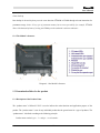
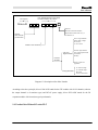
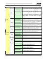
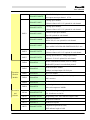


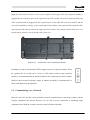
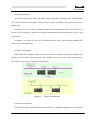
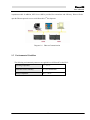
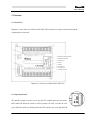
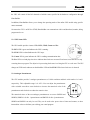
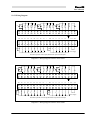
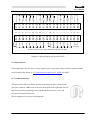
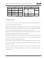

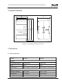

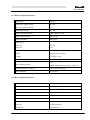
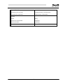

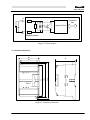


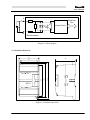
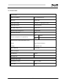

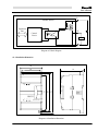


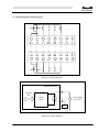
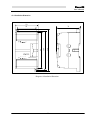


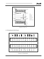

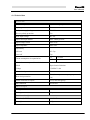

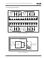


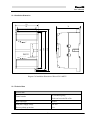
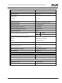


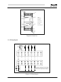
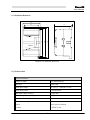
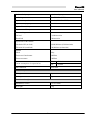


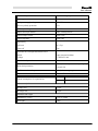
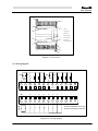
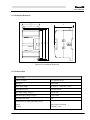


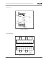
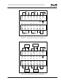
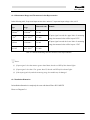
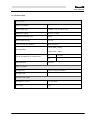


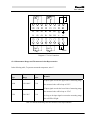


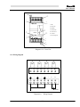

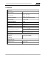


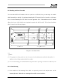
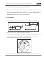


![Model DO402G Dissolved Oxygen Converter [Style: S3]](http://vs1.manualzilla.com/store/data/005725233_1-bd7e4c5bf258da59a958f30153ff00ea-150x150.png)