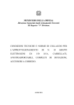
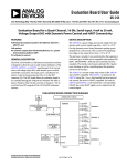
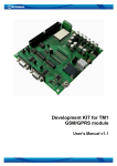
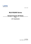
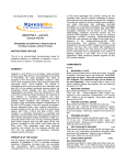
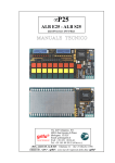
1
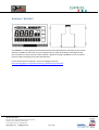
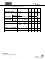
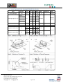
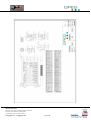
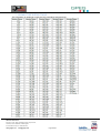
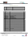
 KickStart
KS008A5
2Line
BigDigitLCD
Product Specification GPEG International Ltd Issue 1.0.0 GPEG International Ltd KickStart™KS008A5
The KS008A5 is a 292‐segment monochrome demonstration/development LCD driven by the unique KickStart™ KS480 LCD controller driver IC. Designed for use with the KickStart™ Development Kit, this LCD allows for demonstration of the KickStart™ platform’s design capabilities or can be used to perform rapid prototyping for product development. For full information on KickStart™ and its LCD design tools visit: http://www.gpegint.com/products/custom_lcd/kickstart/specification GPEG International Ltd 9 Gunnery Terrace, Duke of Wellington Avenue, Royal Arsenal, Woolwich, London. SE18 6SW, United Kingdom Ph: +44 8704 931 433, Fax: +44 208 181 6751 www.gpegint.com [email protected] Page 2 of 14
CONTENTS Contents
KickStart™ KS008A5 ................................................................................................................................ 2 1. FEATURES ................................................................................................................................ 4 2. MECHANICAL SPECIFICATIONS ................................................................................................ 4 3. ELECTRICAL SPECIFICATION ..................................................................................................... 4 3.1. Absolute Maximum Ratings (VSS = 0V) ................................................................................ 4 3.2. Electrical Characteristics (VSS = 0V) ..................................................................................... 5 4. ELECTRO‐OPTICAL CHARACTERISTICS OF LCD ......................................................................... 6 5. TERMINAL FUNCTION .............................................................................................................. 7 6. LCD DRAWINGS ....................................................................................................................... 8 7. SEGMENT DEFINITION TABLE ................................................................................................ 10 8. COMMAND SUMMARY .......................................................................................................... 11 9. RELIABILITY ............................................................................................................................ 12 10. HANDLING PRECAUTIONS ..................................................................................................... 13 GPEG International Ltd 9 Gunnery Terrace, Duke of Wellington Avenue, Royal Arsenal, Woolwich, London. SE18 6SW, United Kingdom Ph: +44 8704 931 433, Fax: +44 208 181 6751 www.gpegint.com [email protected] Page 3 of 14
1. FEATURES
* Display mode: FSTN / Positive / Transflective * Backlight: White LED, 500cd/m2 * Display Format: Digital with 7 & 16 segment characters, bar and icons. * IC: KickStart™ KS480 * Interface Input Data: I2C, SPI (4 Wire) * Driving Method: 1/8 Duty, 1/4 Bias * Viewing Direction: 6 ’CLOCK 2. MECHANICALSPECIFICATIONS
Item Specification Unit Dimensional Outline 75L x 50W x 4.8H mm LCD Size 75L x 45/50W x 2.0H MAX mm Viewing Area 69.94 x 37.72 mm Character Font Digital ‐ Operating Temp. ‐20~+70 °C Storage Temp. ‐30~+80 °C Weight 28 g 3. ELECTRICALSPECIFICATION
3.1.
AbsoluteMaximumRatings(VSS=0V)
Item Symbol
Supply Voltage For Logic VDD‐VSS Supply Voltage For LCD Drive V0‐VSS Input Voltage Range Vin Standard Value Unit Min. Typ. Max. ‐ ‐ <6.0 V 3.8 4 4.2 V ‐0.5 ‐ VDD+0.5 V Note 1) VDD based on VSS = 0V GPEG International Ltd 9 Gunnery Terrace, Duke of Wellington Avenue, Royal Arsenal, Woolwich, London. SE18 6SW, United Kingdom Ph: +44 8704 931 433, Fax: +44 208 181 6751 www.gpegint.com [email protected] Page 4 of 14
3.2.
ElectricalCharacteristics(VSS=0V)
Item Symbol
Test Condition ‐ Logic Supply Voltage VDD – VSS
LCD Drive Voltage ‐ VLCD (Recommended Voltage) “H” Level VIH VDD=3.0V+5%
Input Voltage “L” Level VIL Min. Typ. Max. Unit
2.6 3 3.6 V 3.8 4 4.2 V 2.0 ‐ ‐ 0 ‐ 0.8 3.5 1.0 V “H” Level VOH “L” Level VOL Operating current SLEEP current (LCD on, no wakeup) SLEEP current (LCD on, RTC on, autoprint) SLEEP current (LCD off , RTC on) DEEPSLEEP current IOP VDD = 3V ‐ ISLEEP3 VDD = 3V ‐ 26 ‐ µA ISLEEP2 VDD = 3V ‐ 28 ‐ µA ISLEEP1 VDD = 3V ‐ 6 ‐ µA IDEEPSLEEP VDD = 3V ‐ 0.8 1 µA Output Voltage VDD=3.0V+5%
V 1700 2000 µA GPEG International Ltd 9 Gunnery Terrace, Duke of Wellington Avenue, Royal Arsenal, Woolwich, London. SE18 6SW, United Kingdom Ph: +44 8704 931 433, Fax: +44 208 181 6751 www.gpegint.com [email protected] Page 5 of 14
4. ELECTRO‐OPTICALCHARACTERISTICSOFLCD
Item Symbol Driving Voltage VOP Temp. Min. Typ. Max.
25 θ(Φ=0°) Viewing Angle (Cr ≥2) θ(Φ=180°) θ(Φ=90°) 25 θ(Φ=270°) 25 4.0 4.l2 ‐ ‐ 40 ‐20 ‐ ‐ ‐40 ‐ ‐ ‐ ‐ 35 Unit Conditions Note V ‐ Note 1 Degree
‐ Note 1
Note 2 Contrast Ratio Cr 25 ‐ 4 7 ‐ ‐ Note 3 Frame Frequency Ff 25 32 64 128 Hz ‐ ‐ Response Time (rise) Tr 25 ‐ 80 160 50 ‐ 50 100 ms ‐ 25 ‐ 100 200 50 ‐ 60 120 Response Time (fall) Tf 4.7
5
Note 4 ms ‐ 5.3
GPEG International Ltd 9 Gunnery Terrace, Duke of Wellington Avenue, Royal Arsenal, Woolwich, London. SE18 6SW, United Kingdom Ph: +44 8704 931 433, Fax: +44 208 181 6751 www.gpegint.com [email protected] Page 6 of 14
5. TERMINALFUNCTION
Pin Symbol Function Description
1 GND Ground
2 GND Ground
3 VCC Supply for IC logic voltage +3.3V
4 VCC Supply for IC logic voltage +3.3V
5 BUSMODE Interface select
6 CS/SDA IC select or data input
7 CK Clock input
8 DI/LED3 Data input
9 D0/LED4 Data input
10 EVENT Data input
11 KEYIN1 Switch input
12 KEYIN2 Switch input
13 KEYIN3 Switch input
14 KEYIN4 Switch input
15 KEYIN5 Switch input
16 LED1/BL BL or LED input
17 LED2 LED input
18 BUZZER/LED5
BUZZER or LED input
19 BUZZER/LED6
BUZZER or LED input
20 NC (Factory use only)
GPEG International Ltd 9 Gunnery Terrace, Duke of Wellington Avenue, Royal Arsenal, Woolwich, London. SE18 6SW, United Kingdom Ph: +44 8704 931 433, Fax: +44 208 181 6751 www.gpegint.com [email protected] Page 7 of 14
6. LCDDRAWINGS
GPEG International Ltd 9 Gunnery Terrace, Duke of Wellington Avenue, Royal Arsenal, Woolwich, London. SE18 6SW, United Kingdom Ph: +44 8704 931 433, Fax: +44 208 181 6751 www.gpegint.com [email protected] Page 8 of 14
GPEG International Ltd 9 Gunnery Terrace, Duke of Wellington Avenue, Royal Arsenal, Woolwich, London. SE18 6SW, United Kingdom Ph: +44 8704 931 433, Fax: +44 208 181 6751 www.gpegint.com [email protected] Page 9 of 14
7. SEGMENTDEFINITIONTABLE
This information is needed to access the LCD controller at segment level.
GPEG International Ltd 9 Gunnery Terrace, Duke of Wellington Avenue, Royal Arsenal, Woolwich, London. SE18 6SW, United Kingdom Ph: +44 8704 931 433, Fax: +44 208 181 6751 www.gpegint.com [email protected] Page 10 of 14
8. COMMANDSUMMARY
Normal commands have a general format of:
command, length, payload[], checksum
Symbol
Length
Description
command
1 byte
Command code
length
1 byte
Length of payload[]
payload[]
length
Meaning depends on command code
checksum
1 byte
Sum of all bytes starting from command plus 128
List of commands Code
Symbol
Description
1
Cmd_Seg_Tbl
Load LCD Segment Table
2
Cmd_Obj_Tbl
Load LCD Object Table
3
Cmd_ScrollTxt
Load text for automatic scrolling
16
Cmd_LCD_cnf
Set commons of glass, bias, object count
17
Cmd_Contrast
Set LCD contrast level
18
Cmd_Statread
Read status bytes. Only for SPI mode!
19
Cmd_Reset
Reset KickStart™ LCD Controller
20
Cmd_Set_Seg
Set logical segment on
21
Cmd_Clr_Seg
Set logical segment off
22
Cmd_Obj_W
Write object without conversion
23
Cmd_7seg
Set a 7-segment object to a value
24
Cmd_14seg
Set a 14-segment object to a value
25
Cmd_16seg
Set a 16-segment object to a value
27
Cmd_Bar
Set a bar object to a value
28
Cmd_7seg_Str
Set a 7-segment component to a value
29
Cmd_14seg_Str
Set a 14-segment component to a value
30
Cmd_16seg_Str
Set a 16-segment component to a value
32
Cmd_Bar_Str
Set a bargraph component to a value
33
Cmd_Shift_L
Shifts the values of a component left by one object
34
Cmd_Shift_R
Shifts the values of a component right by one object
35
Cmd_Scroll2Hz
Controls automatic scrolling
36
Cmd_RTC
Set RTC mode, date/time, events, auto-display
37
Cmd_Attr
Set attribute of a component
38
Cmd_LED
Set one LED, including the backlight, on or off
39
Cmd_Buzz
Turn on/off buzzer, set output-mode, frequency
40
Cmd_LCD_OnOff
Turn the LCD on or off
41
Cmd_TestLED
Turn on or off the test functions of the LEDs
42
Cmd_AllSeg_On
Turn on all segments
43
Cmd_AllSeg_Off
Turn off all segments
44
Cmd_Sleep
Set KickStart™ power mode
45
Cmd_SleepLED1
Enable sleep mode indicator function of LED1
Full descriptions of the command set can be found in the KickStart™ User’s Manual. GPEG International Ltd 9 Gunnery Terrace, Duke of Wellington Avenue, Royal Arsenal, Woolwich, London. SE18 6SW, United Kingdom Ph: +44 8704 931 433, Fax: +44 208 181 6751 www.gpegint.com [email protected] Page 11 of 14
9. RELIABILITY
NO. Item Condition 1 High Humidity High Temperature Storage Low Temperature Storage 40°C, 90%RH, 96Hrs 2 3 4 Thermal Shock 60°C, 96Hrs ‐20°C, 96Hrs ‐20°C to 25°C to 60°C to 25°C (30Min)(5Min)(30Min)(5Min) 5Cycles Criterion All test conditions in state, not operating. Note: 1) For restricted products, the test conditions listed as above must be revised. GPEG International Ltd 9 Gunnery Terrace, Duke of Wellington Avenue, Royal Arsenal, Woolwich, London. SE18 6SW, United Kingdom Ph: +44 8704 931 433, Fax: +44 208 181 6751 www.gpegint.com [email protected] Page 12 of 14
10. HANDLINGPRECAUTIONS
1) Mounting Method The panel of the LCD Module consists of two thin glass plates with polarizers which easily get damaged since the module is fixed by utilising fitting holes in the printed circuit board. Extreme care should be taken when handling the LCD modules. 2) Caution when handling & cleaning the LCD When cleaning the display surface, use a soft cloth with solvent (recommended below) and wipe lightly: ‐ Isopropyl alcohol ‐ Ethyl Alcohol ‐ Trichlorotrifluoroethane Do not wipe the display surface with dry or hard materials that will damage the polarizer surface. Do not use the following: ‐ Water ‐ Acetone ‐ Aromatics 3) Caution against static charge The LCD module uses CMOS LSI drivers, so we recommend that you connect any unused input terminal to VDD or VSS, do not input any signals before power is turned on, ground your body, work/assembly table and assembly equipment to protect against static electricity. 4) Packaging ‐ Modules use LCD elements and must be treated as such. Avoid intense shock and falls from a height. ‐ To prevent modules from degradation, do not operate or store exposed directly to sunshine or high temperature/humidity. 5) Caution when operating ‐ It is essential to drive LCD within the specified voltage limit. Driving at a higher voltage will significantly shorten the LCD’s lifespan. An electrochemical reaction due to direct current causes LCD deterioration, avoid the use of direct current drive. ‐ Response time will be extremely delayed at lower temperatures than the operating temperature range. At higher temperatures, the LCDs will show dark colours in them. These phenomena do not mean a faulty LCD; it will return to its normal operation when back within the specified operating temperature range. ‐ If the display area is pushed hard during operation, some characters may be abnormally displayed. They will resume their normal condition after turning off the LCD once. ‐ A slight dew depositing on terminals is a cause for electrochemical reactions resulting in terminal open circuit. Usage under the relative condition of 40°C, 50%RH or less is required. 6) Storage In the case of storing for long periods of time (i.e. Years) for the purpose of replacement use, the following method is recommended. GPEG International Ltd 9 Gunnery Terrace, Duke of Wellington Avenue, Royal Arsenal, Woolwich, London. SE18 6SW, United Kingdom Ph: +44 8704 931 433, Fax: +44 208 181 6751 www.gpegint.com [email protected] Page 13 of 14
‐ Store in a sealed, airtight, polyethylene bag. Do not use desiccant. ‐ Store in a dark place away from exposure to direct sunlight. ‐ Store within the specified storage temperature range. ‐ Do not store with anything pressing on the polarizer surface. It is recommended to store the LCD as they have been contained in the inner container at the time of delivery. 7) Safety ‐ It is recommended to crush damaged or unnecessary LCDs into pieces and wash off the liquid crystal using solvents such as acetone and ethanol to be burned up later. ‐ Any liquid crystal from damaged glass that comes in contacts with hands must be washed off thoroughly with soap and water. GPEG International Ltd 9 Gunnery Terrace, Duke of Wellington Avenue, Royal Arsenal, Woolwich, London. SE18 6SW, United Kingdom Ph: +44 8704 931 433, Fax: +44 208 181 6751 www.gpegint.com [email protected] Page 14 of 14