1
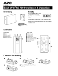
DYNAMIC ENGINEERING
150 DuBois St. Suite 3
831-457-8891 Fax 831-457-4793
http://www.dyneng.com
[email protected]
Est. 1988
User Manual
PCIBPMCX1
PCI, PCI-X 1 Slot PMC Compatible Carrier
Revision A2
Corresponding Hardware: Revision A/B
Fab number:10-2006-1501/2
PCIBPMCX1
PCI and PMC Compatible Carrier
This document contains information of
proprietary interest to Dynamic Engineering. It
has been supplied in confidence and the
recipient, by accepting this material, agrees that
the subject matter will not be copied or
reproduced, in whole or in part, nor its contents
revealed in any manner or to any person except
to meet the purpose for which it was delivered.
Dynamic Engineering has made every effort to
ensure that this manual is accurate and
complete. Still, the company reserves the right to
make improvements or changes in the product
described in this document at any time and
without notice. Furthermore, Dynamic
Engineering assumes no liability arising out of
the application or use of the device described
herein.
Dynamic Engineering
150 DuBois St Suite 3
Santa Cruz, Ca. 95060
831-457-8891
831-457-4793 FAX
The electronic equipment described herein
generates, uses, and can radiate radio
frequency energy. Operation of this equipment
in a residential area is likely to cause radio
interference, in which case the user, at his own
expense, will be required to take whatever
measures may be required to correct the
interference.
Dynamic Engineering’s products are not
authorized for use as critical components in life
support devices or systems without the express
written approval of the president of Dynamic
Engineering.
©2006-2007 by Dynamic Engineering.
Other trademarks and registered trademarks are owned by their
respective manufactures.
Manual Revision A2 Revised 9/24/07
Connection of incompatible hardware is likely to
cause serious damage.
Embedded Solutions
Page 2
Table of Contents
PRODUCT DESCRIPTION
5
Shunt Settings
6
DipSwitch Settings
7
Reserved Pins Routing
10
Options
10
PMC Module Backplane IO Interface Pin Assignment
11
APPLICATIONS GUIDE
12
Interfacing
12
Construction and Reliability
13
Thermal Considerations
13
WARRANTY AND REPAIR
14
Service Policy
Out of Warranty Repairs
14
14
For Service Contact:
14
SPECIFICATIONS
15
ORDER INFORMATION
16
Embedded Solutions
Page 3
List of Figures
FIGURE 1
PCIBPMCX1 PN4 INTERFACE STANDARD
Embedded Solutions
11
Page 4
Product Description
PCIBPMCX1 is part of the Dynamic Engineering PCI and PMC Compatible family
of modular I/O components. The PCIBPMC adapts a PMC to one PCI slot. The
PCIBPMCX1 uses a PCI-X compatible bridge and can operate with PCI-33,
66,100 or 133 speeds. The PMC can operate with a different bus speed, width,
or VIO than the primary bus.
The PCIBPMCX1 has programmable [switch] options for most features.
Special features:
• Universal PCI voltage
• PCI, PCI-X compatible
• Device Hiding and Opaque Memory options
• LED on PMC Busmode “Present”
• LED’s on plus 12V, minus 12V, plus 5V, plus 3.3V, and VIO
• 8A regulator for PMC 3.3V supply
• Selection switch for PCI3.3 or regulated 3.3
• Selectable secondary VIO.
• 32 or 64 bit operation on either bus
• 133, 100, 66 or 33 MHz operation.
• Front panel connector access through PCI bracket
• User IO [Pn4] available through SCSI II connector. Spare pins on SCSI
connector can be shunt selected to power or ground. Routing done as
differential pairs with 100 Ω differential impedance.
• Cooling cutout for increased airflow to PMCs
• Optional Fan(s) to increased airflow
• Optional JTAG programming support
The PCIBPMCX1 is ready to use with the default settings. Just install the PMC
onto the PCIBPMC and then into the system. There are a few settings to
optimize performance.
Embedded Solutions
Page 5
Shunt Settings
Select the appropriate VIO for your PMC. A PMC can be 3.3V or 5V or
“universal”. Please select the 3.3 or 5V VIO choice with the shunt J4. The
Voltage choices are marked. Install the shunt for 3.3V operation; open for 5V
operation.
The VIO plane is a reference for the IO level. The specification does not prohibit
larger current consumption from these pins. The PCIBPMCX1 design utilizes a
MOSFET to control the 5V or 3.3V rails onto the VIO plane. Max consumption
on the VIO rail is 3A. The factory setting is 3.3V on the secondary VIO rail.
Select the 3.3V source for your PMC. Some backplanes have 3.3 and some do
not. Sometimes the isolation provided by an inline power supply is useful.
Sometimes there is not enough 3.3V to supply all of the devices and it is handy
to convert some of the 5V rail to 3.3V. The PCIBPMCX1 has a switching DC/DC
power converter built in.
When shunt J1 is installed the switching regulator is enabled and the backplane
power path is disabled. The switching regulator controls a low impedance
MOSFET to pass the 5V onto the 3.3V rail. When the switching regulator senses
that the voltage is within tolerance the MOSFET is disabled. When the voltage
falls below the threshold the MOSFET is enabled. An inductor and several large
value tantalum capacitors are used to provide “clean” power to the PMCs. The
switching regulator is much more efficient than a linear regulator resulting in
lower heat dissipation and a higher MTBF. When shunt J1 is not installed, the
3.3V rail from the backplane is routed to the PMC. The factory setting is
installed.
Embedded Solutions
Page 6
DipSwitch Settings
Please note that the switch numbering and '1' and '0' definitions are per the silk
screen.
The dipswitches are numbered SW4, SW3, SW1, SW2 from top to bottom and
are located between the PMC connectors. SW3,4 are used to control the PMC
interrupt routing. SW2 is used for the GPIO port. SW1 controls the Bridge
operation. SW 3,4 are oriented with pin 1 to the right and SW1,2 are positioned
with pin 1 on the left [see “dot” in silkscreen]. The “on” position is the closed
position for the switch.
Switch 1: Special selections for the 31154 Bridge
For more information please refer to the Intel® documentation
Position 1 corresponds to S_MAX100. When closed the signal is ‘0’. When
open the signal is ‘1’. When set to ‘1’ the secondary [PMC] side is limited to 100
Mhz in PCI-X mode. The factory setting is ‘0’.
Position 2 corresponds to S_PCIXCAP. When closed the signal is ‘0’. When
open the signal is ‘1’. When set to ‘1’ PCI-X operation is enabled for the
secondary side. The factory setting is ‘0’.
Position 3 corresponds to OPAQUE_EN. When closed the signal is ‘0’. When
open the signal is ‘1’. When set to ‘1’ Opaque Memory is enabled to establish
the Base and limit registers used to create a private memory space. The factory
setting is ‘0’.
Position 4 corresponds to IDSEL_MASK. When closed the signal is ‘0’. When
open the signal is ‘1’. When set to ‘1’ hide the devices attached to the PMC slot
from the host after reset. The factory setting is ‘0’.
Position 5 corresponds to DEV_64BIT#. When closed the signal is ‘0’. When
open the signal is ‘1’. When set to ‘1’ 64 bit operation is enabled for the PMC
slot. The factory setting is ‘0’.
Position 6 is used to ground the Monarch pin J2-64. A pull-up holds the signal
high when the switch is not closed. Revision 2 and later boards are marked in
the silk-screen. Revision 1 boards have rework for this feature.
Embedded Solutions
Page 7
Position 7 corresponds to S_M66EN. When closed the signal is ‘0’. When open
the signal is ‘1’ assuming that the PMC does not pull the signal down. SM66EN
acts as an open drain signal with any of the nodes capable of reducing the clock
rate and all nodes required to operate at the higher rate. Select the secondary
side [PMC] PCI bus frequency. The options are to use the PCI bus speed
[primary] or to force 33 MHz on the secondary side. The PMC to be installed
must be 66 MHz compliant to use the 66 MHz secondary side option. ‘1’ = 66
MHz capable secondary side. ‘0’ = 33 MHz. Please note that PCI-XCAP will
override if set to enabled. The factory setting is ‘1’.
The SM66EN signal is also routed to the PMC connector pin M66EN. If the PMC
uses the M66EN as an input then the dipswitch can be used to control the
frequency. If the PMC uses the M66EN pin as a control, then the Switch may
have no effect. For example if the switch is in the ‘1' position and the PMC is
selecting M66EN = ‘0’ then the PMC will “win” and the signal will be at the 33
MHz setting. Both the dipswitch and the PMC M66EN have to be enabled for 66
MHz operation.
Position 8 corresponds to P_M66EN. When closed the signal is ‘0’. When open
the signal is ‘1’. Select ‘1’ to use the PCI bus speed and ‘0’ to force 33 MHz
operation. If the rest of the cards installed on the same PCI segment ,and the
segment itself are 66 MHz capable then the PCI primary speed will be 66 MHz.
If any device on the segment is set to 33 MHz only then the entire segment will
operate at 33 MHz. We recommend enabling the 66 MHz operation, and using
the bridge to switch to 33 MHz for the PMC. The factory setting is ‘1’.
Switch 2: GPIO
The 8 switch positions can be read in from the bridge via the configuration space
registers. The switch bits 8-1 correspond to the GPIO bits 7-0. The bits can be
used for any purpose – Card numbering etc. The GPIO bits are also connected
to a test point strip. If the GPIO bits are to be used as outputs be sure that the
corresponding switch is in the open position. The factory setting is open.
Embedded Solutions
Page 8
Interrupts from the PMC are connected from the PMC to the primary PCI bus.
INTA through INTD are mapped indirectly to the primary bus segment.
The IDSEL is set to AD20 for the PMC slot [secondary PCI].
The PCI reserved signals are routed to the PMC reserved pins in accordance
with the PMC specification to allow for future signal definitions or special user
signaling.
Embedded Solutions
Page 9
Reserved Pins Routing
PCI
A9
B10
A11
B14
A40
A41
B63
A92
B92
B93
A94
PMC
Pn2-8
Pn2-9
Pn2-10
Pn1-10
Pn1-41
Pn1-42
Pn3-1
Pn3-59
Pn3-63
Pn3-61
Pn3-64
In Addition Jn2 pins 58 and 64 are pulled up to VCC_IO with 4.7KΩ. Pin 60 is
open. This configuration works with most Monarch capable PMCs. Please
contact Dynamic Engineering if you need alternate settings.
Revision 2 and later boards have resistor jumpers for the Reserved pins to allow
for their isolation should your PMC need to be disconnected from the newer
signals. “-RSVD” removes these signals when added to the part number. For
revision 1 boards specific pins can be pulled at the PMC connector.
Options
The PCIBPMCX1 features cooling cutouts designed to support the addition of a
fan in one or two positions for the PMC. On PrPMC's and other PMCs with high
thermal loads the fan option is a good idea. On cards with a lower thermal profile
the fan(s) is not needed. The fan produces 8 CFM in a small area to create a
high LFM rating suitable for most cooling requirements. The fan used has a
relatively low noise rating for quiet operation. Position 1 is closest to the PCI
bezel and position 2 is closer to the PMC connectors.
Embedded Solutions
Page 10
PMC Module Backplane IO Interface Pin Assignment
The figure below gives the pin assignments for the PMC Module IO Interface –
from Pn4 to the PCIBPMCX1 connectors. Also see the User Manual for your
PMC board for more information.
SCSI II [P2,P4]
Pn4
35
36
1
1
2
3
37
38
5
3
4
7
39
40
9
5
6
11
41
42
13
7
8
15
43
44
17
9
10
19
45
46
21
11
12
23
47
48
25
13
14
27
49
50
29
15
16
31
51
52
33
17
18
35
53
54
37
19
20
39
55
56
41
21
22
43
57
58
45
23
24
47
59
60
49
25
26
51
61
62
53
27
28
55
63
64
57
29
30
59
65
66
61
31
32
63
33
67 Open, +5 or GND via J2 silk screen defined
34
68 Open, +5 or GND via J3
FIGURE 1
2
4
6
8
10
12
14
16
18
20
22
24
26
28
30
32
34
36
38
40
42
44
46
48
50
52
54
56
58
60
62
64
PCIBPMCX1 PN4 INTERFACE STANDARD
Read table:
P3-C1 = P2-1 = Pn4-1
P3-A1 = P2-35 = Pn4-2
etc.
Embedded Solutions
Page 11
Applications Guide
Interfacing
Some general interfacing guidelines are presented below. Do not hesitate to
contact the factory if you need more assistance.
Installation
The PMC is mounted to the PCIBPMCX1 prior to installation within the chassis.
For best results: with the PCI bracket installed, install the PMC at an angle so
that the PMC front panel bezel penetrates the PCI bracket then rotate down to
mate with the PMC [PnX] connectors.
There are four mounting locations per PMC. Two into the PMC mounting bezel,
and two for the standoffs near the PMC bus connectors.
Start-up
Make sure that the "system" can see your hardware before trying to access it.
Many BIOS will display the PCI devices found at boot up on a "splash screen"
with the VendorID and CardId for the PMC installed and an interrupt level. If the
information is not available from the BIOS then a third party PCI device
cataloging tool will be helpful
Watch the system grounds. All electrically connected equipment should have a
fail-safe common ground that is large enough to handle all current loads without
affecting noise immunity. Power supplies and power consuming loads should all
have their own ground wires back to a common point.
Power all system power supplies from one switch. Connecting external
voltage to the PCIBPMCX1 when it is not powered can damage it, as well as the
rest of the host system. This problem may be avoided by turning all power
supplies on and off at the same time. This applies more to the PMCs installed
onto the PCIBPMCX1 than the PCIBPMCX1 itself, and it is smart system design
when it can be achieved.
Embedded Solutions
Page 12
Construction and Reliability
The PCIBPMCX1 is constructed out of 0.062 inch thick FR4 material. Cooling
cutouts have been designed into the product for improved air flow to the PMC
sites. The components on the PCIBPMCX1 are tied into the internal power
planes to spread the dissipated heat out over a larger area. This is an effective
cooling technique in the situation where a large portion of the board has little or
no power dissipation.
A fan option is available for high thermal load PMCs or for a chassis with a lack
of air circulation.
Surface mounted components are used. The connectors are SMT for the PMC
bus and through hole for the IO.
The PMC Module connectors are keyed and shrouded with Gold plated pins on
both plugs and receptacles. They are rated at 1 Amp per pin, 100 insertion cycles
minimum. These connectors make consistent, correct insertion easy and reliable.
The PMC Module is secured against the carrier with the PMC connectors. It is
recommended, for enhanced security against vibration, that the PMC mounting
screws are installed. The screws are supplied with the PMC from the OEM.
Dynamic Engineering has screws, standoffs, blank bezels and other PMC
hardware available at a reasonable cost if your PMC was not shipped with some
of the required attachment hardware or if it has been misplaced.
Thermal Considerations
If the PMC installed has a large heat dissipation; forced air cooling is
recommended.
Embedded Solutions
Page 13
Warranty and Repair
Please refer to the warranty page on our website for the current warranty offered
and options.
http://www.dyneng.com/warranty.html
Service Policy
Before returning a product for repair, verify as well as possible that the suspected
unit is at fault. Then call the Customer Service Department for a RETURN
MATERIAL AUTHORIZATION (RMA) number. Carefully package the unit, in the
original shipping carton if this is available, and ship prepaid and insured with the
RMA number clearly written on the outside of the package. Include a return
address and the telephone number of a technical contact. For out-of-warranty
repairs, a purchase order for repair charges must accompany the return.
Dynamic Engineering will not be responsible for damages due to improper
packaging of returned items. For service on Dynamic Engineering Products not
purchased directly from Dynamic Engineering contact your reseller. Products
returned to Dynamic Engineering for repair by other than the original customer
will be treated as out-of-warranty.
Out of Warranty Repairs
Out of warranty repairs will be billed on a material and labor basis. The current
minimum repair charge is $100. Customer approval will be obtained before
repairing any item if the repair charges will exceed one half of the quantity one
list price for that unit. Return transportation and insurance will be billed as part of
the repair and is in addition to the minimum charge.
For Service Contact:
Customer Service Department
Dynamic Engineering
150 DuBois St. Suite 3
Santa Cruz, CA 95060
831-457-8891
831-457-4793 fax
InterNet Address [email protected]
Embedded Solutions
Page 14
Specifications
Logic Interfaces:
PCI, PCI-X Interface 33/32 <–> 133/64
Access types:
PCI bus accesses
CLK rates supported:
133, 100, 66, 33 MHz PCI clock rates
Software Interface:
transparent Bridge. 31154 registers in configuration space
Initialization:
switch selections for VIO, 3.3V source, primary and
secondary clock rates, bridge based features and cable
options
Interface:
PMC front bezel via PCI bracket and User IO connector via
DIN ribbon and or SCSI II connector
Dimensions:
1/2 length PCI board, single PCI slot width with PMC
installed
Construction:
High Temp FR4 Multi-Layer Printed Circuit, Through Hole
and Surface Mount Components.
Embedded Solutions
Page 15
Order Information
standard temperature range 0-70øC
PCIBPMCX1
1/2 length PCI,PCI-X card with PMC positions
-FAN(1,2,12 [fan installed in position 1 or 2 or
both 1 and 2]
-NC [SCSI connector not installed]
http://www.dyneng.com/PCIBPMCX1.html
-RSVD for no connections to PCI reserved pins
-ROHS for ROHS compliant processing
HDEterm68
http://www.dyneng.com/HDEterm68.html
68 pin SCSI II to 68 screw terminal converter
with DIN rail mounting.
All information provided is Copyright Dynamic Engineering
Embedded Solutions
Page 16