1
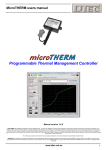
OptiCAL users manual
Manual version 1.0
Computer controlled clock analyser,
calibrator & precision timer
DISCLAIMER: THIS SOFTWARE IS PROVIDED "AS IS" WITHOUT WARRANTY OF ANY KIND, EITHER EXPRESS OR IMPLIED, INCLUDING, WITHOUT LIMITATION, ANY WARRANTY OF
MERCHANTABILITY AND FITNESS FOR A PARTICULAR PURPOSE. IN NO EVENT SHALL THE CREATORS OF THIS SOFTWARE BE LIABLE FOR ANY DIRECT, SPECIAL, INCIDENTAL OR
CONSEQUENTIAL DAMAGES ARISING OUT OF THE USE OR INABILITY TO USE THE SOFTWARE. THE CREATORS AND DISTRIBUTORS OF THIS SOFTWARE SHALL NOT BE LIABLE FOR
ANY LOSS, DAMAGES OR COSTS, ARISING OUT OF, BUT NOT LIMITED TO, LOST PROFITS OR REVENUE, LOSS OF USE OF THE SOFTWARE, LOSS OF DATA OR EQUIPMENT, THE
COSTS OF RECOVERING SOFTWARE, DATA OR EQUIPMENT OR CLAIMS BY THIRD PARTIES, DAMAGE TO EQUIPMENT, OR OTHER SIMILAR COSTS.
www.dtec.net.au
1
OptiCAL users manual
Table of Contents
Note: For your ongoing convenience this manual has been arranged in the order most frequently used. ‘One time only’
items such as software installation, specifications and registration are at the back!
Software Installation
Specifications & Requirements …………..…….
Installation steps ……………..………….….…….
Install notes ……………………………..…………
Registering …………………………………..…….
Simulation Mode ……………………………….….
16
17
18
19
19
Getting Started
Introduction & Features ………………...…..……. 3
Setting up for Testing ……………………….……. 4
Display Screen Overview
Mechanical Period (digital display) .…………..…
Mechanical Period Variation (graph) ……………
Adjusted Mechanical Period (digital display) ..…
Target Period Error % (digital display) ……….…
Adjusted Mechanical Period (graph) ……………
Target Period Error % (bar graph) ………………
Adjusted Mechanical Period (digital display) …..
Target Period Error % (digital display) ………….
Target Period Error % (bar graph) ………………
5
5
6
6
6
6
7
7
7
Tool Bar
Button FunctionsExit ……………………………………….. 8
Start/Stop Calibration ……………….….. 8
Edge Sound Off/On …………………..… 8
Status InformationTarget Period Data ……………………… 8
OptiCAL Hardware ……………………… 8
Menu Options
“File” menuPrint Statement ……………………..…… 9
Set Log File ……………………………… 11
View Log File ………………………….… 11
Log File Directory ……………………..… 11
“Setup” menuHardware ………………………………… 12
Software …………………………………. 12
“Target” menuSet Target ……………………………….. 13
Auto Set …………………………………. 13
“Averaging” menuAveraging cycles ………………………… 14
Clear Averages ………………………….. 14
Display update …………………………... 14
“Utilities” menuCalculator ………………………………… 14
Sync PC to Internet Time ………………. 15
“Help” menuOpen Manual ……………………………. 15
About …………………………………..…. 15
www.dtec.net.au
2
OptiCAL users manual
Getting Started
IntroductionOptiCAL is designed for reducing the tedious and time consuming task of calibrating mechanical
clocks, finally a tool to calibrate and analyse mechanical clocks in minutes, not over months. OptiCAL times
the motion of components instantly and to within 1 micro second for quick calibration.
The controller will accurately time the movement and display the result on a PC via the USB connection. The
supplied software will not only display the instantaneous and averaged period of movement but also allow
logging over long time periods to check for drift due to temperature, tolerances, binding or spring force
variations etc.
Simply locate the optical reflective sensor in a position to detect the movement of the pendulum or similar
component with cyclic motion (could even be a gear or escapement).
Of course, OptiCAL can be used for any precision timing purpose, so long as the sensor head can be located
to sense a suitable object moving in close proximity and were the maximum time measured is less than 10
seconds.
Features•
•
•
•
•
•
•
•
•
•
•
Fast, accurate adjustment due to instant reading of the period
Accuracy, each cycle is timed to the millionth of a second
Customer ‘statement of accuracy’ printed, based on recorded data
Averaged (smoothed) values are displayed as well as immediate
Display of the error from a target value and the variation from cycle to cycle
Digital displays, graphs and bar graphs to help visualise any trends
Records data for later viewing and analysis
Incorporates a remote mount optical sensor with software sensitivity adjustment
No external power required, only the USB connection
Compact dimensions 165L x 25W x 25H (mm)
Individually calibrated, microprocessor based, crystal timing
www.dtec.net.au
3
OptiCAL users manual
Setting up for TestingOptiCAL times the period of a component by sensing its position optically. The sensing ‘head’ contains an
infrared (invisible) light transmitter and a matched detector. The light beam is reflected from a suitable object
and processed to trigger the timing procedure.
Pendulum used as a target (view from the top)
Sensor positioned to detect edge of pendulumNote the focal length (approximately 3.8 mm from sensor)
Sensor can be rotated at any angle, so long as it is
perpendicular (90º) to the objects reflective edge.
OK
also
It is best to turn on the “Edge sound” (button in the ‘tool bar’ at top of the screen) when doing your initial setup.
This will allow audible indication that the object is being detected clearly each period and not ‘double
triggering’ as indicated by more than one ‘click’ sound.
The sensor head should ideally be positioned about 3.8mm from the object being sensed as this is sensors
‘focal’ point, normally you will find it is not critical and simply listening to the ‘edge sound’ to ensure good
object detection is all that’s required. It is best to detect the very edge of the object being timed rather than try
to trigger from some surface feature (such as a raised decorative section).
Mounting the sensor depends on the object being timed and its location. Suggestions are to use a simple wire
stand (bent from coat hanger wire), an engineers dial gauge stand, ‘blu tack’, tape or a stationary paper
clamp such as a ‘bull dog clip’. The main requirement is that the sensor is held stable in relation to the sensed
object. The sensor head can be rotated at any angle but should be perpendicular to the reflective edge being
detected.
As the sensor relies on reflection it is important to have good contrast between the object being detected and
the background.
OptiCAL has a sensitivity adjustment (“Photo Sensor Threshold”) in the ‘setup’ menu. This alters the optical
sensors response to reflective and non-reflective surfaces. Higher numbers (range is 0 – 16) increase the
sensitivity. For example, if the mechanical component being timed is a pendulum that has a matt finish
(tarnished perhaps) then the sensor may not detect it without the sensitivity being increased. Care must be
exercised when adjusting as an overly sensitive setting may cause triggering from surface features other than
the pendulum edge, like decorative contours! Higher settings will also cause issues if there is direct light (eg.
From a desk lamp) present when measuring.
www.dtec.net.au
4
OptiCAL users manual
Display Screen Overview
The main screen is used to display the measured values as they actually occur (‘immediate’) in the upper
panel; the lower panel displays smoothed data (‘averaged’ continually over a user set number of events). If
no hardware is detected OptiCAL will allow simulation mode, this is an excellent way to experiment and learn
the functions listed below!
‘Immediate’
values that
appear as
soon as they
are timed.
‘Averaged’
values that are
smoothed
before display.
Mechanical Period (digital display, 1st row LH)Actual period of the mechanical component (eg pendulum) measured by the optical sensor.
Mechanical Period Variation (graph, 1st row RH)Absolute variation (percentage difference) between each period measurement.
•
•
•
Right hand ‘slide control’ adjusts vertical scale (0% - 10%)
Left hand ‘button control’ sets time scale (200ms – 5min per division)
Over-range symbols can appear RH side to indicate variation is greater than the scale setting.
The small inset window shows the average of the variation (‘averaged’ continually over a user set number of
events)
www.dtec.net.au
5
OptiCAL users manual
Adjusted Mechanical Period (digital display, 2nd row LH)Measured period multiplied by a user multiplier, as selected in the “target” menu. The multiplier is often just
set to 1 as in the above example.
One of the main uses the multiplier is to provide a relationship between the measured component and the
actual time kept by the clock. For example, if the clock pendulum is designed to have a period of 0.5s and
you set the multiplier to 2, the errors displayed will be a percentage of 1 second, not 0.5s.
It is not needed (set to 1) if the data you are looking for does not have to relate to the actual time kept by the
clock. For example, you may be just interested in studying the cyclic behaviour of a gear, escapement or
pendulum to trace irregularities without immediate concern for the actual clocks time keeping error.
The multiplier feature is also of use if a certain number of timed events make up the period required, for
example, if the sensor is positioned to time the rotation of a gear (detecting spokes passing instead of a
pendulum swinging) you could allow for number of spokes sensed per revolution and even create a
relationship between this and the actual clocks time keeping.
Target Period Error % (digital display, 2nd row RH)The error between the ‘adjusted mechanical period’ and the ‘target period’. The target period is what the
period is expected or hoped to be, a target is needed or it’s impossible to display any relative error figure!
In cases were the clock characteristics are not known or you wish to work backwards and determine a target
period for a particular clock then we have provided an “auto set” in the “target” menu.
This “auto set” function calculates a revised ‘target period’ figure by applying a correction factor to your
existing target period. This calculation is based around the average errors; therefore it is best to choose a
large number of “averaging cycles” in the “averaging” menu for maximum accuracy.
Adjusted Mechanical Period (graph, 3rd row)Displays ‘adjusted mechanical period’ as a graph to allow easy viewing of any trends.
•
•
•
•
Right hand ‘slide control’ adjusts vertical scale mid point (50ms – 4950ms)
Inner left hand ‘button control’ sets time scale (200ms – 5min per division)
Outer left hand ‘button control’ sets vertical scale span (2ms – 100ms)
Over-range symbols can appear RH side to indicate period is greater than the scale setting.
A red reference line is displayed horizontally along the graph, this is the target period that you have selected
in the “target” menu.
•
Clicking your mouse on the graph gives the option to automatically vertically centre the red target
period line on the graph for easier scale set up.
Target Period Error % (bar graph, 4th row)Displays the error between the ‘adjusted mechanical period’ and the ‘target period’ to allow easy viewing of
the deviation and the error direction (fast or slow).
•
•
Lower ‘button controls’ adjust graph range (±0.001% – ±100%)
Over-range symbols can appear LH/RH side to indicate error is greater than the range setting.
www.dtec.net.au
6
OptiCAL users manual
Adjusted Mechanical Period (digital display, 5th row LH)This display operates exactly as its counterpart (2nd row LH) but displays smoothed data (‘averaged’
continually over a user set number of events). It has some additional characteristics:
•
•
Number of measurement cycles used to average over can be set in the “averaging” menu (10 – 300)
Display update rate can be set in “averaging” menu for easier interpretation (immediate – 10s)
Target Period Error % (digital display, 5th row RH)This display operates exactly as its counterpart (2nd row RH) but displays smoothed data (‘averaged’
continually over a user set number of events). It has some additional characteristics:
•
•
•
Display also functions as a progress indicator for the averaging process. When you first start timing
events the displays using the averaged data cannot operate until the number of events you have set
in the “averaging” menu have actually occurred.
Number of measurement cycles used to average over can be set in the “averaging” menu (10 – 300)
Display update rate can be set in “averaging” menu for easier interpretation (immediate – 10s)
Target Period Error % (bar graph, 6th row)This display operates exactly as its counterpart (4th row) but displays smoothed data (‘averaged’ continually
over a user set number of events). It has some additional characteristics:
•
•
Number of measurement cycles used to average over can be set in the “averaging” menu (10 – 300)
Display update rate can be set in “averaging” menu for easier interpretation (immediate – 10s)
www.dtec.net.au
7
OptiCAL users manual
Tool Bar
Button FunctionsThe ‘Buttons’ along the top of the screen activate unique functions and display their current operating state
(function active or inactive)
Exit:
Shuts down and exits OptiCAL
Start/Stop Calibration: OptiCAL will start to gather and display the data from the hardware. If the
hardware is not detected (unplugged or ports are configured incorrectly) then this button will display “start
simulation”, this will provide random input data within a small range. Simulation mode is provided as a
convenient way to learn the software functions without needed hardware to be set up.
Edge Sound Off/On: A sound can be produced each time the hardware detects the mechanical
component being timed. This function is invaluable in adjusting the optical sensor against the component and
ensuring it is only triggering as required (ie. not ‘double’ triggering off a nearby feature or component). It is
suggested that the sound be turned off once the hardware is configured as it may impact on the minimum
period that can be timed (the sound generation can ‘tie up’ the PC).
Log to disk Off/On: Logging to disk stores the displayed data to file, this allows later viewing, analysing the
data with other software (eg. a free Excel importing example can be found at DTec.net.au) and most
importantly, logged data is analysed and used to ensure an accurate ‘calibration certificate’ is produced. The
files can be viewed and the storage location set in the “file” menu. When logging, a small counter will appear
at the top of the main screen to keep track of how long the recording has been progressing.
Status InformationThe ‘status information’ along the top of the screen displays import information about the data being used to
calculate the ‘target’ period and the ‘adjusted mechanical period’, also the hardware status is revealed.
Target Period Data: The target period, used to calculate the ‘target period error’, is shown along with the
user set ‘mechanical period’ and ‘user multiplier’ (also used to calculate ‘adjusted mechanical period’). These
values are both entered in the “target” menu and will be discussed further in that manual section.
OptiCAL Hardware: A green ‘tick’ indicates the software is communicating with the hardware, a red ‘cross’
indicates that there is no communication. If this is the case, firstly check that the unit is plugged into the
computer correctly and then confirm that the “setup” menu has the correct port configuration.
www.dtec.net.au
8
OptiCAL users manual
Menu Options
“File” menuAn attractive ‘statement of accuracy’ certificate can be easily printed by OptiCAL, it is based on an analysis of
logged files. These are first checked to ensure they were recorded for of a sufficient duration to provide
accuracy in the report. Logged files also store the data for later viewing or for analysing the data with other
software (eg. a free Excel importing example can be found at DTec.net.au).
Print Statement: Opens a window that allows selection of a saved log file and entry of the appropriate
information required for printing a ‘statement of accuracy’ for the customer.
The “log duration” and “log cycles” recorded for the selected file is shown in Green (bottom LH) if they are
sufficient for an accurate result (minimum of 5 minutes test duration and 500 events). A warning message
appears if these conditions haven’t been met by the selected file, the text will be in Red and no statement will
be printed; a longer testing duration is therefore required.
The logged information used for the statement calculations are the ‘averaged’ values, not ‘immediate’ as this
provides a more realistic result.
A “certificate Number” (top RH) is automatically incremented for each printing and the current date is included
on the final printout. The “theoretical period” figure appearing on the statement comes from the ‘target’ value
that was set when the log file was created; it is automatically appended to your chosen file name when saving
(eg “@0.94980.txt” has been automatically added to “Ansonia – Josephine” in the example below).
www.dtec.net.au
9
OptiCAL users manual
The “print preview/print” button on the setup window allows viewing of the statement and the setup/selection
of printers, a separate print ‘help’ menu is revealed also when selecting a printer and this should be read!
A trial print on plain A4 should be done first before using parchment etc, if not aligned properly then the
“correction” menu will allow for the image to be shifted on the page when printed; most printers have a
positioning error to some extent. When aligning, the image will not alter its position on the screen, only on the
actual page printed.
www.dtec.net.au
10
OptiCAL users manual
Set Log File: Allows the naming of log files before saving and allocates a storage location for them on your
computer. Setting this file name should be the first step before saving any data when using OptiCAL!
When log files are viewed after saving you will see that your saved name has had additional characters
appended, these contain the ‘target period’ value that was set when the log file was created
(eg “@0.94980.txt”).
View Log File: Stored log files can be selected and viewed with this function; it shows all of the recorded
data in columns with a description, also displayed is the ‘target period’ used for the calculations.
Log File Directory: Displays the folders and files that are relevant for locating your logged files, it is more
convenient than windows ‘explore’ as it shows files of the correct log type only (“ .txt” text files).
www.dtec.net.au
11
OptiCAL users manual
“Setup” menuConfigures the hardware and allows the display aesthetics to be altered to your personal taste.
Hardware: OptiCAL software needs to know which PC port the hardware has been allocated to.
Unfortunately, when installing particular USB devices, modern PC’s allocate them to almost any port number
and will even change this depending on what USB socket is being plugged into.
The easiest way to set the “comms port No.” is to plug in the hardware and choose the “AutoFind Hardware”
option. It will step through all of the port options and try to establish communication with the hardware, be
patient as 99 different options are catered for and this can take some time. When found, the port setting is
automatically saved and should remain valid for the USB socket you have plugged into, if you use another
socket you may need to search again.
The communication port can also be manually chosen if it is known. Those with good computer skills can go
into windows ‘device manager’ and view the hardware settings for ports (com &LPT) to check what the PC
has done.
“Photo Sensor Threshold” relates to the optical sensors response to reflective and non-reflective surfaces.
Higher numbers (range is 0 – 16) increase the sensitivity. For example, if the mechanical component being
timed is a pendulum that has a matt finish (tarnished perhaps) then the sensor may not detect it without the
sensitivity being increased. Care must be exercised when adjusting as an overly sensitive setting may cause
triggering from surface features other than the pendulum edge, like decorative contours! Higher settings will
also cause issues if there is direct light (eg. From a desk lamp) present when measuring. Please read the
“setup” section of this manual for more hints on hardware setup.
Software: Display colour schemes can be tailored to your choice and will be stored permanently. A
‘standard’ colour pallet is shown but you can “define custom colours” from its sub menu, up to 32 million
colours are available (dependant on your PC display settings).
www.dtec.net.au
12
OptiCAL users manual
“Target” menuThe target period is what the period of the measured component is expected or hoped to be. A target period
is needed or it’s impossible to display any relative error figure such as the ‘target period error’, it is also used
to calculate the ‘adjusted mechanical period’!
Set Target: The target is composed of the user set ‘measured period’ multiplied by a ‘user multiplier’; the
multiplier is often just set to 1 as in the example below.
One of the main uses the multiplier is to provide a relationship between the measured component and the
actual time kept by the clock. For example, if the clock pendulum is designed to have a period of 0.5s and
you set the multiplier to 2, the errors displayed will be a percentage of 1 second, not 0.5s.
It is not needed (set to 1) if the data you are looking for does not have to relate to the actual time kept by the
clock. For example, you may be just interested in studying the cyclic behaviour of a gear, escapement or
pendulum to trace irregularities without immediate concern for the actual clocks time keeping error.
The multiplier feature is also of use if a certain number of timed events make up the period required, for
example, if the sensor is positioned to time the rotation of a gear (detecting spokes passing instead of a
pendulum swinging) you could allow for the number of spokes sensed per revolution and even create a
relationship between this and the actual clocks time keeping.
Auto Set: In cases were the clock characteristics are not known or you wish to work backwards and
determine a target period for a particular clock. This function calculates a revised ‘target period’ figure by
applying a correction factor to your existing target period. This calculation is based around the average errors;
therefore it is best to choose a large number of “averaging cycles” in the “averaging” menu for maximum
accuracy.
www.dtec.net.au
13
OptiCAL users manual
“Averaging” menuOptiCAL performs a ‘smoothing’ function to appropriate displays; this is done by averaging over a certain
number of events continually, this has the effect of displaying data that is not wildly changing due to small
cyclic mechanical component variations. Too large a number of events and timing disturbances that may be
of interest can be hidden.
Averaging cycles:
Chooses the number of events to average over (10 – 300 events)
Clear Averages: Resets all of the displays showing averaged data to zero, when re-started the displays
cannot operate again until the number of events you have set in the “averaging Cycles” menu have occurred.
Display update: Sets the time period used to update the displays showing averaged data. This can allow
easier interpretation of the displays if the numbers rapidly change (immediate – 10s)
“Utilities” menuOptiCAL provides some additional tools that may be of assistance in your workshop, they are not required for
the actual operation of OptiCAL.
Calculator:
A calculator is displayed for general purpose usage.
www.dtec.net.au
14
OptiCAL users manual
Sync PC to Internet Time: Allows PC synchronisation to an internet time server. Your computer does not
keep accurate time, sometimes varying by up to 30 seconds a day! Your PC can become a 'master clock',
accurate to one second absolute, with no progressive errors. Essential if you wish to use your PC to time
events (ie. referencing a clock against your PC) or to help calibrate equipment.
“Help” menuDirect link to the DTec web site, access to the user manual and software information.
Open Manual: Opens the OptiCAL manual, the manual must be in the ‘OptiCAL’ directory for this function
to operate. We suggest you download the latest manual version from the DTec web site (www.dtec.net.au)
and simply save it in the OptiCAL directory (default directory location is C:\Program Files\OptiCAL).
Of course, you can just download the manual from our website, save it where you please and view as any
other document!
About: Displays software version numbers and copyright
information.
www.dtec.net.au
15
OptiCAL users manual
Specifications
Displayed accuracy
± 1 microsecond at 21 ºC
Maximum period
10 second, software limited
Minimum period
< 0.02s typically, PC speed dependant as readings are updated in ‘real time’
Timer
Crystal oscillator, uniquely calibrated for manufacturing tolerances
Technology
Digital, microprocessor based
Optimal temperature
21 ºC
Communications
USB to computer
Power supply
Powered from computer via the USB connection
Sensor
Optical, infrared reflective transducer
Sensor focal length
3.8 mm optimally
Sensor sensitivity
Software adjustable threshold for contrast compensation
RequirementsOptiCAL is a hardware AND software system. One will not fully work without the other. This manual and
software are freely available for download from the DTec website (www.dtec.net.au). The interface unit
however must be purchased- once again from DTec.
OptiCAL is a ‘WIN32’ application, it should therefore run on Windows 98, ME, 2000, XP and Vista. Earlier
operating systems (such as Windows 95) may encounter issues with compatibility as they may not have the
required USB hardware and support. OptiCAL interface unit derives its power from the USB port (this is
common practice). The interface can run on USB1 or USB 2 ports. However, a small number of older USB 1
systems have limited power supply capabilities; this can be remedied by using a powered USB hub in this
unlikely situation.
A minimum screen resolution of 1024 x 768 is required to fully fit OptiCAL. A smaller resolution will result in
part of the display being outside the viewable area.
www.dtec.net.au
16
OptiCAL users manual
Software Installation
There are basically two parts to the install, the actual OptiCAL software and also a ‘driver’ needed for the
USB connection to your OptiCAL hardware. Just follow the steps below-
Step 1:
DO NOT plug in your hardware, DO close all windows programs.
Step 2:
Download the OptiCAL software (“OptiCAL Installer.exe”) from www.dtec.net.au and save on
your PC, simply execute the program and follow the prompts-
Read and follow the prompts.
Step 3:
You’ll be asked to select a folder in which to copy
the files. We recommend you allow the default
directory, but feel free to choose any.
After the installation above is completed and exited (it will give a completion message and
prompt to ‘exit’).The USB driver screen shown below appears next; if not visible then make
sure it is not ‘hidden’ behind any open windows. Please jump ahead to “Installation notes” if
there are any problems at this stage.
Press “install” button.
When this window appears, just close it and the one beneath it.
Full installation is now complete!
There will be a desktop icon created for you and OptiCAL will appear in your PC’s program list,
along with its uninstalling program that will completely remove the software from your PC.
www.dtec.net.au
17
OptiCAL users manual
Installation notes:
Most issues with the install revolve around the wide variety of PC’s in the market and the any versions of
Windows and its security settings.
Possible USB installation errors• Hardware was plugged in before the install (read step 1 again!).
• Computer requests shut down after OptiCAL installs, but before the USB driver menu appears.
• USB installation menu does not appear.
Solution- Don’t worry! The USB drivers are in the newly created OptiCAL folder (shown below). Just
restart the PC, plug in the hardware, Windows should automatically detect it and check the drivers are
installed, if not, a Windows menu appears and you can allow the PC to search for the driver amongst your
files.
Possible Windows Vista errors• Installation not allowed by Vista security (messages could relate to administration rights)
Solution- Vista has many inbuilt security features, heres some handy hints to help you live with Vista:
If you ‘right click’ on an icon or a program you can choose properties / compatibility tab and then set
“compatibility mode” to run as Windows 2000, also tick “privilege level” to run as an administrator (‘right click’
on an icon or a program will also allow option to run as an administrator directly). Your user account control
(UAC) can also block programs; go into start/ control panel/ user accounts/ turn user account control on or off.
An uninstall program is provided in your PC’s programs list. If there are any installation issues or if you have
been using OptiCAL without having entering the correct registration number (perhaps trialling in simulation
mode) then we suggest you simply uninstall and try again. If you have any problems then please contact us
for assistance!
www.dtec.net.au
18
OptiCAL users manual
RegisteringAfter Installing the Software the next step is to register. When OptiCAL is purchased a registration code is
provided on the invoice (if lost then please contact us for another copy). This code forms part of an internal
calibration sequence and it is very important, for accuracy, that it is entered correctly; every hardware unit has
its own matched number. You will be asked for this code only the first time OptiCAL is run.
In the above example the code provided on the receipt was “opti01-5069”
Simulation ModeIf you just wish to view the software and its functions, but do not posses the hardware, then enter the
following special registration code-
opti01 – 5000
OpiCAL will now allow simulation mode, this is also available with full registration (if the hardware is not
detected.
Note: If you have entered this special number and then purchase the hardware at a later date you will need
to uninstall the software and re-register with the new code as provided on the invoice.
www.dtec.net.au
19