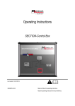
1
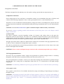
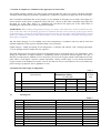
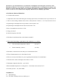
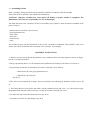
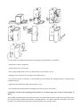
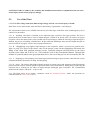
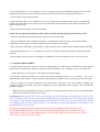
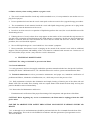
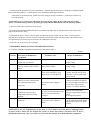
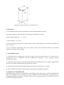
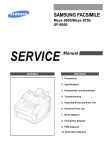
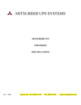
COOLING EQUIPMENT
«SPACE-CABIN»
USER MANUAL
Content
1.
2.
3.
4.
5.
6.
7.
8.
9.
10.
11.
12.
13.
14.
General indications
Description and the concept
Technical characteristics
Marking
Preparation for functioning and use
Safety instructions
Technical maintenance
Probable malfunctions and simple fix methods
Packing
Storage
Transportation
Warranty
Acceptance certificate
Conformity declaration
3
3
5
5
6
9
12
13
13
14
14
15
15
16
1. GENERAL INDICATIONS
The present USER MANUAL contains the description of the device, the concept of its funсtionality, its
technical characteristics and the user manual for the cooling device «SPACE CABIN» (hereinafter,
“Plant”). Also, it contains the necessary rules and regulations concerning the AC Electrical specifications
which must be followed while assembling and installing the Plant.
The Plant is designed for skin and body care, general skin tone improvement and is to be used in skin
care salons, in sport and fitness centers, resorts, sanatoriums, private use and so on.
The Plant by no means, and under no circumstances is to be considered to be medical equipment.
Thus the demands of instruction 93/42/ЕЕС do not apply.
The USER MANUAL is an integral part of the product and should be delivered to the Consumer
along with the delivery and the equipment installation.
Please read all the warnings in this manual carefully. You will find important information relating to the
safety of the Plant, its use and maintenance. Please keep this manual on-site and consult with it any time
you have questions on how to operate or maintain the Plant.
These warnings are designed to ensure the maximum safety of all during the use of the Plant. This manual
will help the Consumer observe the safety demands specified by the Manufacturer and to avoid mistakes,
omissions or problems which may occur during installation or use. The Consumer will take full
responsibility for any and all repair costs if it is determined that any errors or omissions have transpired
during installation or use of the Plant by the consumer.
Another purpose of these warnings, as referred to in this USER MANUAL is to alert the Consumer to pay
attention to safety considerations while the Plant is in use. The present USER MANUAL provides
information regarding detailed instructions of use, installation and maintenance of the Plant to ensure
maximum safety and continuous use of the Plant.
If the Plant is subject to resale or to be passed to another owner and/or it is to be relocated, the
Manufacturer/Dealer must be notified of such action so that a representative may consult and supervise
during the transition. Further, this same representative must take care of the installation of the Plant in its
new location.
The operations room must be at least 81 sq.ft. There are no special requirements for walls and ceiling so it
may be decorated with wallpaper or other finishes as desired by the Consumer. The room’s door frame
must be at least 30” in width. A special opening is to be provided in a wall, ceiling or window pane in
order to mount a crimp tube intended for the used nitrogen vapor expulsion – 5.12” diameter. Note: there
is no need to mount sewerage system or water supply piping. Electric power requirements are – 230-240
Volts, 2-phase. The power plug should be provided with a proper ground contact receptacle.
Only operators specially trained by Manufacturer/Dealer should be allowed to operate the Plant.
Before any maintenance or repair, the Plant should be unplugged.
If safety rules are violated during Plant’s functioning, there is a risk of an accident, serious injury.
2. DESCRIPTION OF THE CONCEPT OF THE PLANT
Designation of the Plant:
The Plant is designed for skin and body care, skin surface cooling, general skin tone improvement, etc.
Composition of the Plant
From a design point of view, the Plant is a monoblock, which is to be assembled at the place of final use and
consists of the following components: client’s cabin, gas preparation device, control board and so-on.
The blocks are to be assembled on common platform, joining each other by assembling bolts. Special seals and
packing ensure the hermetically sealed channels leading from the gas preparation device to the cabin and back
again.
CAUTION : in case of dis-hermetization, please consult the chapter entitled “Safety instructions”.
To view the warnings regarding possible dis-hermetization of the Plant please refer to the Chapter entitled
«Safety instructions».
2.1 Client cabin.
The cabin is destined to provide immediate cooling of a human’s skin surface down to the super low
temperature with the vapor nitrogen. The cabin is of a cylindrical construction which is to be sealed and to be
equipped with a door for the customer’s entrance and exit. Also, the cabin is equipped with system of channels
which ensure the uniform movement of gasiform nitrogen vapor currents within the cabin.
The upper part of the client’s cabin has a channel with a window for recirculation of the gas preparation device,
as well as a line for exhausted air and gasiform vapor evacuation.
The cabin is provided with an electrically-operated hoist (lift) to regulate the level of the client in the cabin
based on the height of the individual.
CAUTION: Client’s contact with liquid nitrogen inside the cabin is absolutely impossible as per its design.
2.2 Gas preparation device.
The device for gas preparation ensures supply and regeneration of gasiform nitrogen which is circulating
through the cabin and its total evacuation from the cabin when the session is over.
The gas preparation device includes: A short cycle contact heat exchange unit, which delivers gasiform nitrogen
into the cabin. The cooling down to temperature minus 200÷275 °F is ensured due to the liquid nitrogen
evaporation.
CAUTION: It is absolutely prohibited to open the gas preparation device cover while the Plant is functioning!
2.3 Cryogenic vessel.
The cryogenic vessel СК-25 or ХА 34 BМ is destined for storage and refilling of liquid nitrogen according to
the Plant’s needs.
CAUTION: All operating personnel must follow all safety measures relative to the storage and handling of
liquid nitrogen, stipulated in this manual for the vessel ХА34 БМ (as defined herein). When working with liquid
nitrogen vessels of a type “Dewar”, it is absolutely prohibited to allow nitrogen drops contact unexposed
human skin.
2.4 System of compulsory ventilation in the upper part of client cabin.
The gasiform nitrogen contains very little oxygen content and thus the zone of its contact with body should be
extremely limited. Hypoxia protection is guaranteed by compulsory ventilation of upper part of the client cabin.
The recirculation/ventilation unit of the system is to be mounted in the upper part of cabin. The height of a
client’s position in the cabin is regulated by hoist (lift unit) – the top of the client’s shoulders must align with
the upper cut of the cabin. There is a ventilation hole provided in the upper part of the cabin which is
facilitating the expulsion the overflow of gasiform nitrogen.
ATTENTION: When working with gasiform nitrogen, its mixture with ambient air (which surrounds us) may
occur in the zone where the operating personnel is stationed, this may cause a lowering of the oxygen content
of this ambient air, causing an oxygen deficiency for the operator. So, the cabin’s doors should not be opened
(unless it is absolutely necessary) until the procedure is over and the automatic evacuation of nitrogen vapor
from cabin is completed.
2.5. All liquid nitrogen is to be handled, stored and transported in accordance with any and all local and
national regulations of the region in which the Plant is to be operated.
Liquid nitrogen – liquid gas boiling at low temperature, is colorless and odorless, with a boiling temperature
77.35 К. Nitrogen itself is neither toxic nor explosive.
The main dangers that exist when working with liquid nitrogen are associated with its low temperature, since
during the evaporation of liquid nitrogen, a considerable portion of gasiform nitrogen appears. This gas, if
allowed to escape into the ambient air of a closed area can lower the oxygen content of the ambient air to the
point where it will impair a person’s normal respiration, causing serious injury or even death. Should the
oxygen content of the ambient air reach a value of less than 6%, loss of consciousness can occur without any
prior warning or symptoms, such as giddiness or such.
2.6. Dimensions and weight of components:
Table 1
Weight, lb,
no more
than
№
Denomination
1
2
3
4
2.7.
Client’s cabinet
Gas preparation device
Electric board
Stage
Dimensions (inch),
Width
30.1
23.6
9.45
20.47
No more than
High
68.9
86.02
31.5
12.6
Length
30.1
50.6
13.77
21.65
265
441
66
22
Packing List:
№№ п/п
1
2
3
4
5
6
7
8
9
10
Denomination
Platform for the power electric board
Gas preparation device
Client’s cabin
Cabin’s door
Control board
Stage
Cryogenic vessel
Fitting and assemblage materials
Extraction air conductor
User manual
Quantity
1
1
1
1
1
1
2+2 additional for extra cost
1 set
1
1
Table 2
Notes
Attention! As per the manufacturer’s specifications, all shipments and subsequent relocations of the
Plant must include the “User manual”, and must be rendered Russian or in English in accordance with
whichever region in which the plant is to be installed. The firmware and all the labeling which the Plant
carries, as well, are to be rendered in the language stipulated by the Shipping Agreement.
3. TECHICAL CHARACTERISTICS
3.1. Technical characteristics
1. Temperature in the client cabin during the executing of procedure is from minus 200 °F up to minus 275 °F
2. Time to reach working conditions in the client’s cabin (from 80 °F down to – 130 °F) not more than 30 sec.
3. Liquid nitrogen consumption for one procedure, not more than 6.6 lb.
4. Liquid nitrogen consumption for the start not more than 7.7 lb.
5. Power consumption not more than 1.5 kw.
9. Voltage 230-240 V
10. Network frequency 50/60 Hz.
3.2 The Plant is manufactured due to the climatic demand N.
3.3 The normal functioning requirements and conditions are as follows:
•
The environment temperature (indoor)
(60-80)°F;
•
Relative humidity (indoor)
(30-50)%;
3.4 The Plant’s construction has the safety level of manufacture IP54.
3.5 Time of uninterrupted service of the Plant 120 min.
3.6 The service term of the Plant is 10 years originating from the date of its manufacture.
3.7 The hoist lifts a client to the high not less than 11.8 inch.
3.7 Maximum weight the hoist lifts – up to 245 lb.
3.8 Recommended temperature in cooling device – from minus 184 to minus 274 °F.
3.9 Acoustic pressure – less, than 70dBa.
4. MARKINGS
4.1 Plant Markings
4.1.1. The Plant’s labeling is shown on label (pic 2).
This label is fixed on the electric board, which is close to the start device and contains the data as follows:
•
Denomination of the type of the Plant - «SPACE-CABIN»;
•
Cryocarrier – liquid nitrogen;
•
Power network voltage-230 - 240V;
•
Network frequency- 50/60Hz;
•
Consumption power not more than 1.5 kw;
•
Safety level IP;
•
Year of manufacture;
•
Serial number ;
•
Made in Ukraine
•
The Right to be marked CE is reserved
Manufacturer Company
"CRIOMED Ltd"
Cooling Plant
SPACE CABIN
~ 230-240 V 50/60 Hz; class І
Power consumption
1, 5 kw
Security level
ІР 54
Cryogenic-component
liquid nitrogen
Year of manufacturing
200___
made in Ukraine
Serial number
CE
Pic 2 The format of the marking label on the Plant.
4.1.2
4.1.3
The Manufacturer’s Company trademark is situated on the face part of gas preparation device.
The Dealer’s Company trade mark may be situated on the face part of gas preparation device.
5. PREPARATION FOR PLANT’S FUNCTIONING AND USE.
Plant’s assemblage, fitting and initial start-up should be realized by an authorized representative of the
Manufacturer/Dealer.
\
5.1. Assemblage Order
Plant’s assembly, fitting and initial start-up should be realized in compliance with the assembly
instruction, which is attached to the shipment documentation.
CAUTION! Improper Assembly may cause injury and damage to people, animals or equipment. The
Manufacturer does not bear responsibility for any such damages.
The Plant delivered to the Consumer consists of 6 modular pieces (blocks), which should be assembled at the
place of end use:
- platform (base) with electric power board;
- gas preparation device;
- client cabin;
- cabin door;
- control board;
- stage;
The assembly begins with the preparation of the site for cryosauina’s installation. This should be a flat, level
surface site with an inclination of no more than 0.5% (5 mm per 1m of length).
ASSEMBLY INSTRUCTION:
1. After the site has been prepared, the platform is to be mounted on the site being aligned as shown in Figure:
(Pos № 1) as illustrated below;
2. The gas preparation device is to be mounted on the platform been fixed by 4 bolts М10 х 22 (Pos № 2);
3. The platform (raised part) is destined for the client’s cabin and is to be fixed by:
- 3 bolts М10 х 60 to the gas preparation device;
- 3 bolts М10 х 40 to the base.
(Pos № 3);
4. The door is to be mounted on its hinges. The test of hermetic seal and integrity should be carried out (pos. №
4);
5. The control board is to be fixed to the cabin’s wall by combined screws М6 х 60 – 6 ps., then fix the wedgeshaped belt inside the board with section sq. А l=600 мм of tension ensured (pos. № 5);
6. To adjust the step to meet the cabin entry area (pos. № 6).
7. Attach by screws the air superchargers (pos.№ 7)
5.2 After Plant’s assembly been finished, the initial start-up and testing can commence:
- connection of electric equipment;
- ground connection (if necessary);
- test of wedge-shaped belts tension (by belts flexion not less than 0.6 inch);
- mounting of air conductor for evacuation of discharged gases;
- test start and control of efficiency of all mechanisms and including the operating abilities at idling motion
(without nitrogen);
- preparation and installation of the liquid nitrogen vessel;
- test of full operational functionality including trials in the presence of the Buyer.
CAUTION! An incorrectly mounted ground contact or its absence may cause a risk of serious injury or
death.
All assembly and installation work performed on the site and the Plant should be conducted by personnel whom
have been specially qualified and trained by the Manufacturer. The Plant should be connected to the power
network in accordance with national and regional regulations for consumer safety.
CAUTION! Failure to abide by the assembly and installation instructions as stipulated herein can cause
serious injury, death and/or property damage.
5.3.
Use of the Plant
CAUTION! The voltage used in the Plant is high voltage and can case serious injury or death!
5.3.1 There are two main modes, when the Plant is functioning: «Operational »; and «Drying».
The «Operational» mode serves to fulfill consecutively all of the stages of the flow sheet (technological cycle). It
consists of 4 sub-modes:
5.3.1. А – Refilling. The Plant is switched on, the aspiration pipe is placed in the upper position. The door is
opened at the base and the Dewar vessel of liquid nitrogen is rolled in on wheels until it is seated in its proper
receptacle. Check the match of the vessel’s mouth with air superchargers. When the lowering of aspiration pipe is
finished, the process of refilling is finished also. In the sub-mode «Refilling» about 8.8 lb of liquid nitrogen are
to be moved from cryogenic vessel to the gas preparation device.
5.3.1. B – «Supplying» step supplies liquid nitrogen to the evaporator, where it converts into gasiform state.
Then it is ready to be passed to the client’s cabin via the mixture system. In the «Supplying» sub-mode, the
filling of the cabin with gasiform nitrogen occurs. Gasiform nitrogen will drop down to the lower
sections of the cabin and in 20-30 sec., will reach the level of the recirculation channel. Through this
channel it’s partially taken to the gas preparation device, the rest of the gas is to be evacuated by the fan.
5.3.1. C – Pumping out. The pumping out of discharged gasiform nitrogen vapor from the cabin after the session
is finished should be facilitated via crimp, flexible piping.
5.3.1. D – Pause. The «Pause» Sub-mode indicates the state of certain aspects and operations of the Plant during
pauses between sessions. It means periods of personnel shift or short-term stand by. During these periods only the
extraction fan is working for the effect of liquid nitrogen discharged gases evacuation. The recommended
duration of the «Pause» sub mode – is up to 5 min.
5.3.2. The Plant works in two modes: “automatic” mode or “automatic-manual” mode. All operations are
controlled from the control board (dr. 3).
Millennium ICE, Inc
tel: 877-ICE-4395
1
4
2
5
3
1. REFLEXION OF TEMPERATURE IN CABIN
2. NITROGEN SUPPLY TIME PAUSE REFLEXION
3. REFLEXION OF PROCEDURE TIME OR TIME
TO THE PROCEDURE BEING FINISHE OR
TIME THE CURRENT MODE BE FINISHED
4. TIME THE CURRENT MODE BE FINISHED
INFORMATIONS DATA
5. THE STATE OF NITROGEN VOLUME
6. PLAN’S START
7. STOP
8. MAINTENANCE
9. DISCONECTION OF PLANT
10.START
11.HOIST (moveable floor of cabin ) UP
12.PIPE UP
13.TO INCREASE THE PROCEDURE TIME
14.PRIMERY COOLING OF THE PLANT
15.HOIST (moveable floor of cabin ) DOWN
16. PIPE DOWN
17.REDUCE THE PROCEDURE TIME
18.DRYING OF THE PLANT
19.INCREASE THE TIME OF NITROGEN SUPPLY
20.INCREASE THE PAUSE TIMEBETWEEN
NITROGEN SUPPLY
21.INCREASE THE TIME OF VENYILATION
AFTER PROCEDURE
22.MEMORY
23.REDUCE THE PAUSE TIME OF NITRIGEN
SUPPLYINGS
24.REDUCE THEPAUSE TIME ВРЕМЯ ПАУЗЫ
BETWEEN NITROGEN SUPPLYINGS
25.REDUCE THE VENTILATION TIME AFTER
PROCEDURE
Dr. 3. The layout of the control board.
5.3.3 GUIDELINES AND PROCEDURE FOR REFILLING PLANT WITH LIQUID NITROGEN.
-In connecting the Plant to an electric power source 230-240V 50/60Hz. Use a power plug with PROPER
GROUND connection only.
- To supply electric power, for this purpose displace the start switch of the Plant «Power» on the right side of the
Plant in the “up” position, press the red button (6) located on the control board. The liquid nitrogen vapor
evacuation fan starts working simultaneously with the start of this phase of operation.
- Lift the intake pipe by pressing down the button (12) on the control board to put the cryogenic vessel with liquid
nitrogen into the refilling compartment and press button (16) on the control board.
5.3.4. STARTING INSTRUCTIONS FOR THE PLANT «SPACE-CABIN»
- Put the switch «POWER» in upper position. Press the red button placed on the control board (6)
- Press button (18) «DRYING» for 5-10 minutes.
- Press button (7) “STOP”.
- Press button (12), after this, the liquid nitrogen pipe will be raised.
- Install the standard cryogenic vessel into the refilling compartment by pressing down button (16).
- Press button (14) for pre-cooling the Plant. If the Plant has been idle for more than 1 hour use pre-cooling
procedure again.
- By pressing down the (+) or (-) buttons: (13) or (17) located on the control board the operator can set-up the
planned time of the next session. New time of the session will be indicated on the monitor display (3).
- Ask the client to step inside the cabin.
- By pressing down the (^) or (v) buttons: (11) or (15) located on the control board the operator can adjust the
height of moveable floor to the proper level of elevation which is the alignment of the client’s shoulders with
upper cut of the cabin.
- Press button (10) «START» on the control board.
- NOTE: The operator must maintain verbal contact with the client throughout all the whole session.
- After the session has been finished, ask the client to step out of the cabin.
- After all sessions have been finished for the day, you should take off the cryogenic vessel from refilling
compartment, and the pipe for refilling should be returned to the lower position.
- Press button (18) «DRYING» for 60 minutes. After the time has been expired device switches off automatically.
- Press (and hold down for 1-1.5 sec.) button (9) “OFF”, wait for the control board monitor panel to switch off
(go dark).
- Switch off the electric power by switching the «POWER» switch on the right side to the “down” position.
5.3.5 SESSION PROCEDURES
- Set the desired time of the session and refer to display panel (3) situated on the control board. The available
time frame for each session is between 60 and 240 seconds. Labeled (+) or (-) buttons: (13) or (17) control this.
- Ask the customer to step inside the cabin and close the door tightly.
- If necessary, adjust the height of the client lift by using the height control (^) or (v) buttons: (11) or (15)
situated on the control block. Lift of lower the client until top of shoulders are level with the top cut of the cabin.
- Press the button (10) «Start» situated on the control block. After that starts, the automatic refilling with
cryogenic component working vessel will commence in the gas preparation device and the cabin will fill with
gasiform nitrogen.
-
When the session is finished the automatic evacuation of cold gas from the client’s cabin occurs and the Plant
returns to the readiness mode for next session.
CAUTION! Before using the device first time for the day and when all sessions are finished for the day (or after
every 20 sessions whatever is first) the operator should dry the gas preparation device. For this purpose, take off
the cryogenic vessel from the refilling compartment and lower the intake pipe to the low position. Press button
(18) «Drying».This will start drying procedure. The procedure will stop automatically in 60 minutes if not
terminated earlier by the operator.
DURING THE PROCEDURE IT IS NECESSARY FOR THE OPERATOR TO CONTROL THE
PROCESS OF REFILLING OF CABIN WITH GASIFORM NITROGEN AND TO OBSERVE AND
ASSESS THE CLIENT’S STATE THROUGHOUT THE ENTIRE PROCEDURE AND AT ALL TIME
WHEN THE CLIENT IS IN THE CABIN.
6.
SAFETY INSTRUCTIONS/PRECAUTIONS
…while operating Plant and while storing, moving and handling liquid nitrogen vessel type “Dewar”:
1. During the session, control of the cabin’s refilling with gasiform nitrogen vapor is very important.
2. At all times throughout the session, the operator should observe and asses the state of the client inside
the cabin.
3. It is the responsibility of the operator to insure that it is impossible for gasiform nitrogen to be inhaled
by the client by adjusting the movable floor lift of the cabin, and by having the client lift their head back to
avoid rising vapors if necessary.
4. In order to avoid overcooling of lower extremities it is the responsibility of the operator to ensure that
the client puts warm (wool or cotton only) socks and cotton pants (the same applies to women’s bra or
brazier if necessary) before being allowed to enter the cabin. During the session the client should move
slowly.
5. In order to avoid overcooling of upper extremities, the client should raise his hands up to the upper
level of cabin (put on the upper edge of cabin).
6. Do not open the cabin door (unless it is absolutely necessary) until a session been finished and
automatic evacuation of gasiform nitrogen from the cabin has completed.
7. In case of emergency opening of cabin (gasiform nitrogen discharges into the ambient air), a 1-2 min air
ventilation is highly recommended.
8. Under no circumstances should and liquid nitrogen come into contact with the skin. As such, the Dewar
vessels must be closed only with covers specially designed for this purpose.
9. It is prohibited to close the vessel’s mouth tightly because evaporation of liquid nitrogen creates excessive
pressure inside the vessel. The increased pressure creates the danger of vessel’s damage and/or unintended
discharge of liquid nitrogen.
10. In case of the contact of liquid nitrogen with skin, the affected area should be immediately washed with
large quantities of water.
The operating personnel should know and observe all safety instructions and precautions. Any violation
should be considered a violation of the discipline of the operator’s service, which should be met with
severe reprimand or disciplinary actions or even legal action in compliance with the Laws and regulations
of the region in which the Plant is being operated.
6.1 Rules of Safety when working with the cryogenic vessel
1. The vessel’s mouth should be closed only with its standard cover, it is not permitted to use another cover or
plug for this purpose.
2. It is not permitted to insert into the vessel cotton pads or other accessories for cryogenic therapy procedures.
3. The accumulation of such material inside the vessel with liquid nitrogen may generate an ice plug inside
the vessel and cause the destruction of the vessel.
4. In order to avoid an excessive evaporation of liquid nitrogen from the vessel, the vessel should be stored far
from heating devices.
5. If during the use of vessel «a hoar-frost» strip appears on the surface of the vessel and this strip increases in
size due to the evaporation of liquid nitrogen, this might indicate a vacuum loss. In this case, the liquid nitrogen
should be removed from the vessel and then the vessel must be heated and dried for 24 hours. After this
procedure, the vessel should be repaired.
6. Never refill liquid nitrogen in a vessel which has “lost vacuum” symptoms.
7. Please remember, that internal vessel is hanging on the mouth of the external vessel with no additional
supports. Thus all operations and handling of the vessel must be conducted with extreme care. Careless use of
the vessel (strikes, drops, and etc.) may cause the vessel’s destruction.
8. TECHNICAL MAINTENANCE
CAUTION! The voltage of 230-240V is present in the Plant!
7.1. General indications
7.1.1 Only personnel, who have thoroughly studied the operations manual and who have the Special Certificate,
issued by the Dealer: “Millennium ICE”, Inc. should be allowed to work on, operate and maintain the Plant.
7.2. Technical maintenance involves preventative maintenance and proper use, immediate rectification of
problems and failures, elimination of malfunctions, etc., which may occur in the process of use.
7.2.1. Daily maintenance includes dust elimination and simple cleaning of interior part of the cabin with soft
flannel cloth. The moveable floor cleaning with wet soaped flannel cloth should be done daily and any dirt
particles should be removed immediately.
7.2.2. Instructions for Maintenance and Service:
-
Examination and verification of the proper functioning of all components and operations of the Plant.
CAUTION! Before beginning any service or maintenance, the Plant must be unplugged from the 230V
power outlet.
FAILURE TO OBSERVE THIS SAFETY PRECAUTION MAY RESULT IN SERIOUS INJURY OR
DEATH.
7.2.3. A thorough service and maintenance should be performed after the first 14 months from the date of the
Plant’s manufacture. This work is to be fulfilled in accordance with the agreement of post-guarantee service.
This work includes:
- verification of the operation of electric equipment; - checking the hoist function; - changing of wedged shaped
belts of the hoists (lifts)в; - re-lubricate the screw mechanism of the pipe and hoist;
-
verification of the hermetically-sealed state of air chargers and air conductors - verification of three way
valve functioning.
CAUTION! In case of emergency shut down of electric power supply in the room where the cooling
device is installed during a session, operating personnel should immediately take the following actions:
1. Open the cabin’s door and let the client go out;
2. Switch off the automatic differential device (located on the right side of control board), remove the power
plug from the electric outlet;
3. Wait until the power will be restored, make sure the main power switch is in the “OFF” (down) position,
plug the power cord back into the electrical receptacle, switch on the Plant, lift take-in pipe, take off the vessel
of liquid nitrogen, lower the pipe and activate the «DRYING» function;
4. After this, the sessions may be continued.
8. PROBABLE MALFUNCTIONS AND RECTIFICATIONS”
8.1.Common solutions of probable malfunctions is indicated in table 1.
Table 1
№№
of order Description of malfunction
its symptoms
1
When the motor is working,
intake pipe will not lift
2
When the motor is working, the
client’s platform will not lift or
lower
3
Mechanisms will not switch on
4
5
6
After pressing down the red
button (6) on the control board,
the control board does not
switch on
The temperature in client’s
cabin does not lower up to
temperature indicated in this
manual.
The control board does not
switch on
Probable cause
Belt’s tension failure
Belt’s tension failure
power is not being supplied to the
Plant, or the automatic power
supply device is switched off.
.
The electric power supply is
absent
Means of elimination
Correct the belt’s tension to the
proper setting
Correct the belt’s tension to the
proper setting
Check that the power plug is
properly inserted into the wall
receptacle, switch on the main
power switch.
Open battery compartment
(situated inside the box behind
the control board below the grey
cover) and verify or fix the
contacts. Or replace batteries
Shortage of liquid nitrogen in the
Dewar vessel or bellows are
damaged.
Increase the expulsion of
nitrogen using button (19) in 1-2
values.
To change the bellows.
The electric power supply is
absent
Verify the switcher “POWER”
(on the right literal of the Plant),
which must be placed in upper
position.
CAUTION! In the case of malfunction of the Plant or severe failure, the Plant must be unplugged from
its power source. Please do not attempt any repair or direct intervention. Non-observance of abovementioned caution may cause sever injury or loss of life and damage of the Plant and other equipment.
Please seek the services of qualified personnel whom are authorized to repair and maintian of this
equipment by the Manufacturer.
9. PACKING
9.1 Each item to be shipped is to be placed on a pallet and packed in corrugated cardboard box or pressed
cardboard box. The dimensions of each packed piece, as to its length, width and high are indicated in table 2
below:
Table 2
Width W, mm,
High H, mm,
Length L, mm,
Denomination
Not more
Not more
Not more
1. Cabin
900
900
1800
2. Power block (gas generator) +
800
1200
1300
electric board + stage
3. Foot + 2 Dewar vessels
800
950
1300
9.2 All the technical and shipping documentation of the Plant to be delivered is involved in polyethylene bag
and placed in main box № 2 with the electric control board.
9.3 Each box carries inside a packing list, in accordance with table 3:
№
of place
1
2
3
Denomination
Quantity of pieces.
Notes
Cabin
1
-
1+1+1
-
1+2
-
wer block (gas generator) + electric board +
stage
foot + 2 Dewar vessels
9.4 The front part of the box carries the most important labeling and handling instructions:
•
•
•
•
•
•
Number of cargo pieces – indicated in fraction such as “number 1 of 3”
Information inscription:
Dimensions of piece in centimeters;
Net weight and gross weight in kilograms;
Volume of the piece in cubic meters;
The inscription «export», «made in Ukraine».
Handling Instructions:
•
«Handle with care, fragile»;
•
«Up»; |^|
•
«Keep Dry»;
•
«Lift here».
The box bears the trade mark of the Manufacturer.
The place of application of signs and inscriptions including lineal dimensions is shown in drawing 4 below:
Drawing 4. External appearance of packed block .
10. STORAGE
10.1 The Plant should be stored in packed form, in a heated and ventilated warehouse.
The storage conditions of the Plant should correspond to the demands as follows:
- Environmental temperature (15…24)°С;
- relative humidity (30…45)%;
10.2 The storage place must be free of harmful steams, acids, alkaline solutions, or any other agents which may
cause corrosion.
10.3 The maximum recommended term of the Plant’s storage when maintained under the above-stated
conditions is not more than 18 months.
11. TRANSPORTATION
11.1 The Plant may be transported by any kind of transport, except on an open decks of sea ship due to the
transportation rules in compliance with the transportation regulations in force regarding maritime
transportation of cargo.
11.2 Placement and securing of a packed Plant during transport should be free of any strikes, displacements,
inversion or any other potentially damaging conditions or actions.
11.3 The pallet allows loading /unloading/relocation by means of loading device i.e:. forklift.
11.4 The conditions of the Plant’s transportation are stipulated in the Shipment Ageement.
12. WARANTY OF THE DEALER
The Manufacturer guarantees the performance and reliability to the cooling device’s Technical Specifications
under the condition that the Consumer has fully complied with the manufacturer’s specifications for
transportation, handling, installation, assembly, initial start-up, testing and regular use as defined herein and in
the sales and shipping agreements.
The manufacturer shall warranty this product from defect for a period of 36 months from the date of receipt of
the Plant as per the delivery receipt or waybill, but not more, than 36 months from the date of shipment to the
Consumer.
The Plant must be used only in compliance with the indicated specifications and instructions for its usage. The
usage in any other manner will be considered as misuse. The DEALER or MANUFACTURER does not bear
any responsibility for any misuse or failure to follow the manufacturers recommended installation, testing,
regular usage, safety precautions, transportation, maintenance and repair.
During the above-stated term of the manufacturer warranty, any sub-system or component is defected by fault
of the manufacturer, the Consumer has the right to repair or replacement, free of charge. In this case the spares
to be repaired or changed during the guarantee term are ensured with guarantee for the rest of primary guarantee
term.
The Manufacturer does not bear any responsibility of guarantee and does not accept any gratis maintenance of
the Plant cases as follows:
А) There is evidence of non-qualified or unauthorized repair of the Plant.;
B) If the defect is caused by changes done in the construction or electric scheme not authorized by the
Manufacturer.
C) If alien objects such as: substances, liquids, insects, animals and so-on are found inside the Plant causing
damage.
D) Non observance of warnings, specifications and instructions as to the Plant’s regime of use as defined in this
present manual.
E) Unauthorized de-installation and relocation (transportation) to another place of operation without the
manufacturer’s knowledge.
F) If the cause of damage was determined to be due to an accident caused by power supply alterations,
lightning, fire, flooding and other natural causes or acts of God.
The guarantee term is not subject to extension, renewal or any other change if a consequent resale takes place.
13. ACCEPTANCE CERTIFICATE № _____ OF COOLING DEVICE (kept with the Consumer)
Technical characteristics:
1. Temperature inside the client cabin during the procedure is from minus 166°F up to minus 274°F.
2. Time to reach operation regime in client’s cabin: not more than 30 sеc.
3. Liquid nitrogen consumption for one procedure: not more than 6.6 lb.
4. Nitrogen consumption during primary cooling: not more than 7.7 lb.
5. Consumption power, not more than 1.5 kW; Power voltage 230-240 V; Power frequency 50/60 Hz.
Dimension:
-
Length – not more than 2000 мм; - Width – not more than 1900 мм; - Height – not more than 2300 мм.
The set of Plant «SPACE CABIN» fabrique № _____ year of manufacture _________, passed, assembled
_________________________________________ on its site. Cooling device received in the full set and in a
good working order. The personnel to work at the Plant has been fully trained as to its proper use, maintenance,
and shall observe all safety instructions and precautions as defined herein «User manual » with the Certificate
issued of the matter CERTIFITAE № ______.No claims and remarks.
This Acceptance Certificate of cooling device is composed of two copies, one copy for each party.
ON BEHALF OF DEALER
Millennium ICE, Inc
_________________________________
«
» _________________ 200___ г.
ON BEHALF OF THE BYUER
_______________________________
_______________________________
« » _________________ 200___ г.
Stamp
Stamp
-----------------------------------------------------------------------------------------------------------------------------------------13.1. ACCEPTANCE CERTIFICATE № _____ OF COOLING DEVICE (kept with Dealer)
Technical characteristics:
1. Temperature inside the client’s cabin during the procedure carrying out from minus 166 °F up to minus 274
°F.
2. Time to achieve operation regime in client’s cabin, not more than 30 sеc.
3. Liquid nitrogen consumption for one procedure, not more than 6.6 lb.
4. Nitrogen consumption during primary cooling, not more than 7.7 lb.
5. Consumption power, not more than 1.5 kW; Power voltage 230-240 V; Power frequency 50/60 Hz.
Dimension:
Length – not more than 2000 мм; - Width – not more than 1900 мм; - High – not more than 2300 мм.
The set of Plant «SPACE CABIN» fabrique № _____ year of manufacturing _________, passed,
assembled_________________________________________ on its site. Cooling device received in the full set
and in a good working order. The personnel to work at the Plant has been formed as for use, maintenance, and
main rules of safety measures due to the present «User manual » with the Certificate issued of the matter
CERTIFITAE № ______.No claims and remarks.
The present Cooling device Acceptance Certificate been composed in two copies, one copy for each part.
ON BEHALF OF DEALER
ON BEHALF OF THE BYUER
Millennium ICE, Inc
_______________________________
_________________________________
_______________________________
«
» _________________ 200___ г.
« » _________________ 200___ г.
Stamp
Stamp
14. CONFORMITY DECLARATION
We hereby the «CRIOMED» LTD declares than the Plant «SPACE-CABIN» corresponds to all the necessary
instructions, demands and standards:
98/37/EC
Demand for Machines
Standards: EN ISO 12100-1:2003, EN ISO 12100-2:2003, EN ISO 13732-3:2005
2006/95/ES Instructions for low voltage equipment
Standard: EN 60335-1: 2002
2004/108/EC Instruction for electric and magnetic coincidence
Standard: EN 61000-6-3:2001, EN 55014-1:2000, EN 61000-6-1:2001,
EN 61000-4-4:2004, EN 61000-4-5:1995, EN 61000-4-11:2004, EN 55014-2:1997