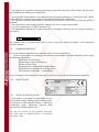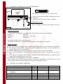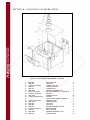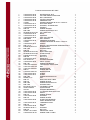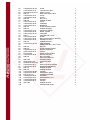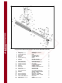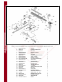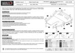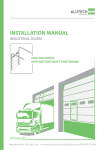
1
OPERATION MANUAL
WINTER MILLING MACHINE
SF 45 FST
WARNING!
The operator must thoroughly read this manual before operation.
Keep this manual for future reference.
Henrik Winter Holztechnik GmbH
Druckereistr. 8
04159 Leipzig
Tel: +49 (0)341/ 4619021 Fax: +49 (0)341/4618358 Funk: +49 (0)171/2820443
Em@il: [email protected] Internet: www.winter-holztechnik.de
MACHINE:
MILLING MACHINE
TYPE:
SF 45 FST
OPERATION MANUAL
T O O UR C UST O M E R S
This manual contains all the instructions required for the faultless operation of the machine and its respective maintenance, as well.
Thus, during the warranty period, you will receive for free all components that have
presented eventual defects.
The producer is always at your disposal for resolving of problems that machine operators may encounter during operation, and for delivery of spare parts, too.
Your recommendations related to this manual are valuable contribution to the improvement of the products offered by Winter Holztechnik GmbH to its customers.
Page 2
MACHINE:
MILLING MACHINE
TYPE:
SF 45 FST
OPERATION MANUAL
СONTENTS
SECTION A: GENERAL DATA
A.1. MANUFACTURER
A.2. INTRODUCTION
A.3. CORRESPONDENCE
A.4. NAME PLATE
A.5. FIELD OF APPLICATION
A.6. WORKING CONDITIONS AND REQUIREMENTS
A.7. ТECHNICAL CHARACTERISTICS
A.8. NOISE CHARACTERISTICS
SECTION B: SAFETY OF WORK
B.1. SAFETY INSTRUCTIONS
B.2. DESIGN MEASURES FOR ENSURING SAFETY FOR WORK
SECTION C: ASSEMBLY OF MACHINE
C.1. REQUIREMENTS TO THE WORKING AREA
C.2. UNLOADING OF MACHINE
C.3. DESLUSHING OF MACHINE
C.4. FOUNDATIONS LAYOUT
C.5. ASSEMBLY OF THE DISASSEMBLED UNITS
C.6. CONNECTION TO THE MAINS
C.7. CONNECTION TO THE ASPIRATION DEVICE
SECTION D: FITTING AND OPERATING OF MACHINE
D.1. OPERATING OF MACHINE
D.2. CONTROL PANEL
D.3. STARTING
D.4. STOPPING
SECTION E: DESCRIPTION OF MACHINE
E.1. TECHNOLOGICAL PART
E.2. ELECTRICAL PART
SECTION F: MAINTENANCE
F.1. CLEANING OF MACHINE
F.2. LUBRICATION OF MACHINE
F.3. CHECKING THE CONDITION OF SOME UNITS AFTER OPERATION
F.4. TROUBLE-SHOOTING
SECTION G: APPENDICES
G.1. WIRING DIAGRAM AND LIST OF THE ELECTRICAL COMPONENTS
G.2. ELECTRIC CABINET – LAYOUT OF COMPONENTS
SECTION H:
CATALOGUE OF SPARE PARTS
Page 3
MACHINE:
MILLING MACHINE
TYPE:
SF 45 FST
OPERATION MANUAL
SECTION A: GENERAL DATA
A.1. MANUFACTURER
Henrik Winter Holztechnik GmbH
Druckereistr. 8
04159 Leipzig
Tel: +49 (0)341/ 4619021 Fax: +49 (0)341/4618358 Funk: +49 (0)171/2820443
Em@il: [email protected] Internet: www.winter-holztechnik.de
A.2. INTRODUCTION
The present manual is designed for those who will operate the machine. You will find in it the necessary data for assembly, commissioning, maintenance and safety operation of the machine. The experience
of the company manufacturer and its experts in considered in the preparation of this manual.
We recommend you to consider with responsibility our recommendations concerning the safety of
work. The operations requiring disassembly of machine and electrical components should be performed
by authorized and qualified personnel only. Repairs and settings not described in the present manual
should not be performed. This manual is prepared by the manufacturer and is an integral part of the machine's delivery. The information contained herein is intended for specialists and is compulsory.
The manual defines the machine's field of application and contains all the information necessary for its
proper and safety operation.
The permanent and exact observation of the instructions contained in this manual ensure safety of personnel and machine, profitable work as well as long life of the machine itself.
For better clarity this manual is divided in separate parts in which are contained the more important
subjects.
The contents will allow you to find fast the specific subjects.
The important text is printed in bold and is marked by the following symbols:
WARNING
This means that you should proceed very carefully in order to avoid situations that could be dangerous to human life or may cause serious injury to the personnel.
ATTENTION
Provides information about situations that may occur during the life of the product, the system or
the equipment and that may cause injury to the personnel, damages on the machine, environmental
pollution or financial loss.
CAUTION
Means that you should be more cautious in order to avoid material damage.
i
INFORMATION
Very important instructions.
Some figures and information in this manual may not coincide with those of the machine purchased by
you.
Page 4
MACHINE:
MILLING MACHINE
TYPE:
SF 45 FST
OPERATION MANUAL
The producer is constantly working on the improvement and renovation of the product and may introduce modifications without prior notification.
At preparation of this manual are considered all the operations belonging to "normal servicing". Repair
works and other operations not mentioned in the manual should not be undertaken.
All operations requiring disassembly of machine parts should be carried out by technically qualified
personnel.
The instructions of this manual should be observed for correct usage of the machine.
Use only original spares of ZMM "Stomana" JSC.
The manufacturer should not be held responsible for damages caused by the use of spares which are
not original.
i
INFORMATION
The machine can be operated and serviced only by specially trained personnel, well acquainted
with this manual.
A.3. CORRESPONDENCE
In case of technical problem please contact the Seller or Service department.
In the correspondence or telephone call with them concerning the purchased machine please supply
the following information:
ß Machine serial number
ß Operating voltage and frequency
ß Date of production
ß Detailed description of the eventual failure
ß Detailed description of the working process
ß Total time of operation – working hours;
In case of enquiry concerning the electrical part is necessary to provide the data from the name plate.
A.4. NAME PLATE
A.5. FIELD OF APPLICATION
This machine is designed for longitudinal for profiling, prickle cutting, folding, pattern milling (copying) of wood or other materials similar to wood (e.g.
wooden-fibre plates, chipboards, plywood, laminated and non-laminated planes etc.)
You may not process on this machine materials,
other than those as indicated above, or materials
other than wood.
Page 5
MACHINE:
MILLING MACHINE
TYPE:
SF 45 FST
OPERATION MANUAL
A.6. WORKING CONDITIONS AND REQUIREMENTS
ATTENTION
The machine is designed for one operator only.
А – place of work during profiling, folding, pattern milling (copying).
В – place of work during work with moving table.
Tools that may be used:
May be installed and used on the machine tools comfig. 1
A-B
Working environment
The machine is designed for operation under the following environmental conditions:
Humidity
Max 90%
Temperature
Min +1°С Max +40°С
Altitude
Max 1000 м
The machine should not be open-air operated.
The machine should not be operated in environment presenting danger of explosions.
Defense to operate
ß The operation of the machine under conditions differing from those above mentioned is prohibited.
ß The operation of the machine without the protection devices provided, as well as the removal of
any part of those devices, is prohibited.
ß Materials differing from those described above may not be processed on the machine.
ß Pieces, whose dimensions differ from those described above, may not be processed on the machine.
ß Tools that do not comply with pr. ЕN847-1 and tools, whose dimensions do not comply with the
cutting disk shaft diameter may not be used.
ß Introduction of modifications in the machine is prohibited.
The sole and exclusive liability in case of injury of personnel and damages of the machine as a result
of processing of unspecified materials shall be borne by the machine operator.
A.7. ТECHNICAL CHARACTERISTICS
Dimensions of the working board
Dimensions of the mobile board
Mobile board run
- to the left
- to the right
Working table’s elevation above the floor
Exchangeable cutter arbour (Morse taper)
Diameter of the cutter arbour
Working length of the cutter arbour
mm.
mm.
mm
mm
mm
mm
mm
Т1002L
1000х650
1600х350
T1002S
1000x650
1150х350
1115
1115
850
МК4
ø30
125
730
730
850
МК4
ø30
125
Page 6
MACHINE:
MILLING MACHINE
TYPE:
SF 45 FST
OPERATION MANUAL
Vertical run of the spindle
Spindle tilting (backwards)
Aperture diameter of the working board
Maximal diameter of the tools:
- during profile milling
- during tongue milling
Max. depth of tool run ø 250 bellow the table surface
mm
(°)
mm
180
0°-45°
ø260
180
0°-45°
ø260
mm
mm
mm
ø250
ø300
60
ø250
ø300
60
Turning frequency of the spindle (with a 3-phase
3000/4000/5000/
3000/4000/5000/
min-1
motor)
6000/8000/10000
6000/8000/10000
Two-speed motor, 3-phase, 400V, 50 Hz
kW (HP)
3.2/4.0 (4.3/5.5)
3.2/4.0 (4.3/5.5)
Diameter of the rings, covering the aperture of the
mm
ø206, ø156, ø110, ø70 ø206, ø156, ø110, ø70
working board
Diameter of the aspiration hose
-above the working board
mm
ø120
ø120
- under the working board
mm
ø120
ø120
Tool protector for ø250mm with integral rulers
mm
2 х350
2 х350
Machine dimensions
mm
1350 х 1000 х 850
1800 х 1000 х 850
Machine weight, approximately
kg
446
430
Dimensions of the packing
mm
1750 х 1300 х 1100
1750 х 1300 х 1100
OPTIONS
Rotating ruler for milling without extension
Rotating ruler for milling with extension
Extension for the working board to the left, right
Extension for the working board to the
Console table
Tool protector for ø250mm with integral rulers
Changeable cutter arbours МК4
Left / right spindle rotation
Tenoning table and tenoning hood ø 320 mm
Horizontal and vertical pressing device “MORI”
Detachable control board
Feeding mechanism МХ38, МХ48
Two-speed motor, 3-phases
One-speed motor
One-speed motor
Spindle rotation for the one-speed motor
mm
mm
mm
mm
mm
mm
mm
kW (HP)
kW (HP)
kW (HP)
min-1
900
900
500х320
500х320
500х320
2 х500
ø1 ¼”, ø32, ø40, ø50
900
900
500х320
500х320
500х320
2 х500
ø1 ¼”, ø32, ø40, ø50
4.5/5.5 (6.1/7.4)
5.5 (7.4)
7.5 (10.1)
4000//6000/8000
4.5/5.5 (6.1/7.4)
5.5 (7.4)
7.5 (10.1)
4000//6000/8000
A.8. NOISE CHARACTERISTICS
ATTENTION
A continuous noise exposure over above 85 dВ (А) may result in health injury. That is why we
recommend to use in such cases noise protection devices like ear-plugs, earphones, etc.
Statement on the emitted noise:
1. /А/ weighed level of noise pressure at idle
LpfA = 74 dB
Indefiniteness К = 2 dB
2. /А/ weighed level of noise power at material processing
- LwA = 103 dB
Indefiniteness - К = 2 dB
At 95% probability
Page 7
MACHINE:
MILLING MACHINE
TYPE:
SF 45 FST
OPERATION MANUAL
SECTION B: SAFETY OF WORK
B.1. SAFETY INSTRUCTIONS
ATTENTION
Before commissioning, use, servicing, repair, cleaning or any other operations on the machine
read very carefully this manual.
The manufacturer shall not be liable for any damages on the machine or any injury of personnel
occurred as a result of failure to observe the operation, maintenance and safety instructions.
ß Only persons who have normal brains, are well grounded in exploitation of machine and dangers can
work on it.
ß Observe operation manual.
ß During activities for supporting preparation for work disconnect power cord from mains.
ß Before putting into operation always check safety devices.
ß Operating with gloves is forbidden.
ß After closing work clean machine from dust and chips.
ß Keep working space of the machine always clean.
ß Never clean machine with water neither when on nor when off.
ß Before starting operation remove from machine and working space all adjustment tools.
ß Always observe that machine is switched off when any electrical connection is due.
ß Use machine and tools for the correct application only.
ß Do not operate machine in humid spaces or leave machine exposed to rain or low temperatures.
ß Never leave machine operating without supervision when you are away.
ß Do not operate with widely clothing, free hair and long shawls.
ß Bracelets, watches, chains, etc. to be removed.
ß Operate machine with headphones to avoid noise.
ß Always use protective glasses, mask against dust or use other prescribed safety devices.
ß Keep children away from machine and take that children have no access to it.
ß Teenagers under 16 years may operate the machine under the supervision of experienced workers.
ß When machine is operated for longer periods a connection to aspirators for dust and chips removal is
recommended.
ß Before starting work check up details for defects like knots, nails and other foreign ingredients.
ß Use only perfectly sharpened tools.
ß Do not use cracked, damaged and irregular sharpened tools.
ß Observe always rotation of cutting tools used not to exceed maximum rotations prescribed by the respective tool manufacturer.
ß Clean joinable surface of tool carefully and check up for swellings and injured places on them.
ß Never clean tools with wire brush and water.
ß With tools use protective gloves.
ß Never open protective covers and doors when machine is operating.
ß Never hand or other parts of your body to moving parts or materials.
ß Operate only materials for which machine are intended.
ß When installing machine observe oncoming light (500 Lx) not to blind operator and avoid stroboscope
effects.
ß Transporting, installing and assembly of machine must be done only by skilled staff.
ß Only skilled staff can do all interventions in electrical equipment.
ß Never change electrical equipment.
ß Device for sucking out dust and chips must secure output least 1800 m3/h at speed 25-30 m/s.
ß Do not switch on machine at open covers of electrical equipment (electrical cupboard, desks, engines).
ß Around machine must have enough place to be sure worker wile be always out of dangerous places.
ß Regularly clean the table and the floor of dust and chips.
Page 8
MACHINE:
MILLING MACHINE
TYPE:
SF 45 FST
OPERATION MANUAL
ß When stopping machine to adjustment, repair, supporting, cleaning etc. put the main switch in position
“zero”, warn workers with plate and lock the main switch with padlock.
ß The key from the padlock must be in you self.
Training of servicing staff
All persons servicing machine must be trained for using and adjustment it.
The training must consist in:
- basic principles for moving of machine rules for using, adjustment of fulcrum ruler etc..
- correct operating with details during the work.
- position of hands toward tool during the work and after working.
Servicing staff must be inform about dangers during curing using the machine and about safety work.
Servicing staff must be trained for doing periodic checking of safety equipment.
Servicing staff must be informed about safety equipment.
Additional dangers
Despite all operation and safety rules contained in this Operation and service manual, the following
additional dangers may occur:
- Contact with the tool;
- contact with the rotating parts of the driving (pulleys, belts etc.)
- Back hit of the piece or parts thereof;
- Possible danger of dust when operating without aspiration device.
However, the safety depends mainly on yourself.
Bear in mind that you always undertake some risk when operating the machine.
B.2. DESIGN MEASURES FOR ENSURING SAFETY FOR WORK
The machine includes the following safety equipment and measures:
ß Milling support with fulcrum rulers and protective box.
Serve:
1. As support for precisely leading of the detail.
2. As protective box (safety lock) against touching unused during the work part of tool.
3. As collector of chips with tip for inclusion toward equipment for sucking out dust and chips from
working surface of the table.
Cover of the protective box can open upward and gives possibility for change of the tool without dismanting of the box.
The equipment for vertical and horizontal pressing of details toward the table can be assembled on the
protective box.
ß Set of hoops on the milling mandrel cover the whole height.
ß Insurance hoop on the milling mandrel prevents allocation of the tool during the stopping of turning.
ß Bolt for make fast the tool on milling mandrel.
ß Hoops cover the outlet in working table.
Give possibility for optimum covering of the outlet in the table.
ß Adjusting milling mandrel along height and slope from 90 to 45 with possibility of fixing in adjusted
position by blockade rods.
ß Blockading of milling mandrel against turning.
It secures immobility of mandrel at allocation and making fast of the bolt during the changing of tool.
ß Moving table with telescopic fulcrum ruler which can turn in borderlines -45 to +45 and device for
making fast the detail on the moving table.
Moving table secures safety work of details with big sizes.
ß Bracket table.
ß Irreproachably tools.
Page 9
MACHINE:
MILLING MACHINE
TYPE:
SF 45 FST
OPERATION MANUAL
Blunted and damaged tools create danger from opposite hit, overload the machine and create vibrations and bad surface of detail.
ß Helping equipment.
We recommend using helping equipment during the special operating:
1. Wood piece for pushing the detail at the end of operation.
2. Protective box for covering the tool during the prickle cutting.
3. Additional table with protective shields for prickle cutting, assembled on the moving table (carriage).
4. Cross supports for notch cutting.
5. Prolongations of the table for operating of long details.
6. Device for arched milling.
7. Feed gear etc..
Helping equipment must be always in good working order near the machine.
ELECTROEQUIPMENT
ß Electronic brake for electrodynamics stopping of engine.
It secures stopping of turning of mandrel for time less that 10 seconds after turning off the engine.
ß Minimum voltage protection.
After stopping of voltage the machine stops working, but at restoration of voltage it stays at rest.
ß Breakdown stop on main desk.
Turn off switch for control and interlock of milling mandrel during changing of tool. It prevents
starting of machine during the changing of tool.
ß Circuit breaker for choosing speed of rotation of mandrel.
ß Protective earthling.
ß Protection of engine against overloading (by built in thermocontacts).
ß Stage of protection of electrical apparatuses IP 54.
ß Turn off switch of back door.
It prevents starting of the machine at open door.
ß Light indication for shat revolution.
Page 10
MACHINE:
MILLING MACHINE
TYPE:
SF 45 FST
OPERATION MANUAL
SECTION C: ASSEMBLY OF MACHINE
C.1. REQUIREMENTS TO THE WORKING AREA
ß Choose suitable place for machine accordfig. 2
ingly moving of movable table.
ß Observe described in section 3 prescriptions.
ß Chosen in advance place for fixing the machine must secure convenient joining toward
electrical mains and device for sucking out
dust and chips.
ß Secure suitable lighting (500 Lx), which does
not blind eyes and avoids stroboscope effects.
ß Check up bearing ability of floor. Machine
must be leveled on four points of rest simultaneously.
ß Besides it is necessary to secure distance least
of 0.8 m / 31 ½ in. around the machine.
At input and output of the machine must be secured necessary space for handing and taking down of
long details.
C.2. UNLOADING OF MACHINE
The hoisting and shifting of the machine must be carried out by suitable personnel especially
trained for that kind of work and disposing of the required equipment.
WARNING
During loading and unloading operations the machine must be handled with extreme precaution
and hits and pushes must be avoided in order to prevent injury of personnel and damage of the
goods.
During hoisting and shifting there must be not people near to the load hung or within the operation scope of the crane
The shifting of the machine and its parts must be carried out only by transportation means that correspond to the weight of the machine, e.g.
- fork-lift truck;
- wheelbarrow;
- crane;
D
ATTENTION
A
C
For hoisting of the machine you will need a forklift truck with fork long at least 1200 mm.
- Ensure a fork-lift truck A with the required loading
capacity corresponding to machine’s weight.
- The fork B should be brought under the machine in
a way as presented in fig. 3.
B
In case you dispose of crane or other similar means,
act as follows:
- prepare 2 ropes or belts C with the required loading
capacity and length.
fig. 3
Page 11
MACHINE:
MILLING MACHINE
TYPE:
SF 45 FST
OPERATION MANUAL
- The ropes should be hung on the hook of crane D with loading capacity corresponding to that of machine’s weight.
- The ropes are hoisted by the crane and are hung on the four hooks provided for the hoisting of the machine.
WARNING
Check the secure fixing of the hoisting hooks to machine’s body.
ß Adjust the ropes well and, if required, the crane should move slightly apart in order to ensure the
stable vertical hoisting without inclination of the machine.
ß The machine must be hoisted slowly and with extreme precaution in order to avoid pushes and
swinging of the load.
ß After the machine is hoisted at 1 m height, stop the hoisting and mount the four leveling supports to
machine’s body.
ß Place the machine on the chosen location by means of the crane.
ß Level the machine by means of the four leveling supports in order to effect a stable state.
C.3. DESLUSHING OF MACHINE
Remove the anti-corrosion grease from all unpainted machine parts using kerosene, turpentine or ordinary cleaning products commercially available.
Do not use nitro- thinners or similar diluents and by no means use water.
C.4. FOUNDATIONS LAYOUT
The stable construction of the machine, ensuring precise leveling and vibration-free operation does not
require any foundations.
C.5.
ASSEMBLY OF THE DISASSEMBLED UNITS
With view to the transportation and packaging, some parts of the machine are delivered in unassembled condition
You will find hereafter instructions concerning the assembly of those parts.
C.5.1. Assembly of bracket table for support of details
E
D
F
A
G
B
C
H
Assembly guiding wedge A (fig. 4) (together
with washers B and handles C) in “T- channel”
D on the moving table E.
Widen bind fast handles C so that to hand up
bracket table F on the pins with thread of the
handles C.
After that bind fast handles C so that level the
bracket table with moving table by tuning screw
G.
Bind fast handles C finally to fix bracket table
F.
fig. 4
Page 12
MACHINE:
MILLING MACHINE
TYPE:
SF 45 FST
OPERATION MANUAL
C.5.2. Assembly of the handle for moving of the mould table its cover, support of details
Assembly of the handle for the moving of the movable table
D
H
G
E
F
C
- Remove the packing tape from lever N and screw O.
- Dismantle the transport screw and nut O
- Unscrew handle A (fig. 5) from feather B so it is necessary to enter feather B in “T- channel” C.
- After tuning in definite position in channel C bind
fast handle A again.
Assembly of cover with the handle
fig. 5
A
- Unscrew 4 number screw D /fig. 5/;
- Assemble cover with handle E toward mould table F.
- Screw and bind fast screws D again.
B
Assembly the support for circumcision
- Widen handle G /fig. 5/;
- Assemble feather H in one of channels J or I on the mould table F.
- After tuning of the support in definite position on the table, bind fast the handle G again.
C.5.3. Assembly of the fulcrum ruler with bind fast mechanism
- Fix feather A (fig.6) toward pad C centering along
spring pins;
- Screw column D and handle C in feather А;
- Put assembled ruler on the mould table E so that
feather A to move in one of the two channels В;
- After defining position of ruler toward mould table E
E bind fast column D with help of bracket F.
B
D
C.5.4. Assembly of the horizontal and vertical
pressing mechanism on the protective box (option)
C
A
B
C
G
A
fig. 6
- Unscrew fully nuts from bolts A (fig. 7) on the cover of protective
box В.
- Assemble pressing mechanism C on the cover of protective box B
and bind fast well by bolts A and nuts .
C.5.5. Assembly of the
protective box with
pressing mechanism on
the work table
fig. 7
- Put centering plank D
(fig. 8) so that pins enter
E
A
B
in outlets C on working table B.
- Put the protective box A on the working table B so that its
channel to enter in centering plank D.
- bind fast protective box A toward working table B by handles
Е.
fig. 8
D
C
Page 13
MACHINE:
MILLING MACHINE
TYPE:
SF 45 FST
OPERATION MANUAL
C.5.6. Assembly of the protective box during the cutting of prickle (option)
During cutting of prickles it is necessary to use special protective box.
- Dismantle the protective box for work with fulcrum
rulers from the table.
- Put protective box A (fig.9) for work cutting of prickle
on the working table B and center it toward thread outlets С.
- Bind fast protective box A toward working table
B by handles D.
C.5.7. Assembly of the cutting board on the format board (option)
A
D
B
C
fig. 9
С
H
В
- insert nut A in the lateral T-shaped groove B of
the format board C (fig. 10).
- Install the guide D to the format board C by
means of the tightening lever E and nut A.
- insert key F along with the screw G inside the
L
groove H of the format board C.
A
- install the cutting board I on the format board
J
C in a way to make the groove J coincide with
М
the threaded aperture K of the key F, and the
F
guide D to enter in the groove L of board I.
D
- screw up the axle-guide M in the threaded apG
К I
erture K of the key F without completely fastenО
A N
fig. 10
Е
ing it.
- now you can move the cutting board along the length of the format board in the required location.
- by means of screw G fix the key F in the groove H.
- check the motion of the cutting board in transversal direction compared to the format board. Provided
the motion is not perpendicular to the format board length
- release counter-nuts N.
- you can adjust, by means of screws O, the cutting board
I towards the format board C or towards the parallel rulers
of the milling cutter’s rest.
- Tighten again the counter-nuts N.
А
C.5.8. Mounting of the detachable control board (option)
Fix the carrying pipe А (fig. 11) to the machine's board В
through the screws and the washers C.
B
C
fig. 11
Page 14
C.5.9. Mounting of the extension table (option)
Two persons are required for this operation.
Mount the extension table D to the fixed
table В through the levers А and the washers.
Tighten slightly the levers А.
You can level, if necessary, the front rim of
the extension table to the fixed table through
the screws F and C ; fix it in this position
with the nuts E.
Tighten finally through the levers А.
D
F
B
C.6. CONNECTION TO THE MAINS
ATTENTION
А
The connection of the machine to the
electric mains, as well as all subsequent
checks, must be carried out by electrical
technician only.
E
C
Фиг. 12
ß Check by suitable apparatus the good condition of the nullifying and earthing device.
ß Check whether the supply voltage and frequency of the current correspond to the data stated on machine’s plate.
The deviation of the supply voltage must not exceed
+ 5 %. (for instance: a machine operating under supply voltage of 400V can work within 370 to 420 V).
ß In order to define the required section of the supply cable, refer to the data of the amperage, stated on
machine’s plate, as well as to the table below:
Electric current (А)
Up to 10
from 10 to 14
from 14 to 18
from 18 to 22
from 22 to 28
from 28 to 36
From 36 to 46
Section of the cable
2.5 mm2
2
4.0 mm
6.0 mm2
6.0 mm2
10.0 mm2
10.0 mm2
16.0 mm2
Fuse
12А АМ
16А АМ
20А АМ
25А АМ
32А АМ
40А АМ
50А АМ
ß We do recommend to use a rubber insulated supply cable type
H07RN (WDE0282) and to take the necessary measures for its
protection from mechanical damages.
ß Connect the supply cable to the respective terminals in the incoming electric board (L1,L2,L3,N,PЕ) (fig. 13).
ß Provided there is CEE socket available (380V, 16A), the connection to the mains is carried out by means of respective CEE
plug (L1,L2,L3,N,PЕ).
ATTENTION
During initial commissioning and after each modification of the
fig. 13
connection to the three-phase mains, check whether the direction of rotation of the shaft corresponds to that indicated on the plate. Provided the rotation is in
the opposite direction, change the connection points of the three-phase cables L1 and L2.
Page 15
C.7. CONNECTION TO THE ASPIRATION DEVICE
The chip and dust aspiration device must ensure a minimal rate of air delivery of 1800 m3/h at a speed of
25-30 m/sec.
ATTENTION
The dust and chips aspiration device must be switched on
simultaneously with the motor of the machine.
The machine is supplied with two tips for sucking out dust and
chips. The first tip A, with diameter ø100 mm, is sucking out
dust and chips under working surface of the machine table
/fig.12/.
The other tip B, with diameter ø120 mm, is sucking out dust
and chips from protective box over the working surface of the
A
machine table /fig.13a/.
Connect rubber materials toward tips A and B and bind fast Фиг. 13а
them with clamps.
The device for sucking out dust and chips must have two tips or to use special fork-joint.
B
Page 16
SECTION D: FITTING AND OPERATING OF MACHINE
D.1. OPERATING OF MACHINE
D.1.1.General instructions during the milling operation
ß Before starting the work with the milling mandrel be sure that the tool is assembled correctly toward to turning direction and it is binded fast hardly.
ß Be sure that milling mandrel is turning freely by hand.
ß Putting at the position of the mandrel at height must be done always from down to up to avoid the
influence of eventual windages.
ß Milling must always starts and finishes along the wood fiber direction.
ß The feed of detail must do uniformly without pushing’s.
ß Tool must be covered as it is possible /by hoops in the machine table and by safety equipment/.
fig. 14
fig. 15
ß Tool must be binded fast lower
on the mandrel to avoid vibrations
/fig. 14 and fig. 15/.
G
D
E
Recommended
Do not recommended
C
ATTENTION
B
ß Use only suitable for the machine tools. Observe data of the
producer (diameter – revolutions).
ß Observe correct fixing of the tool accordingly the turning
direction of the mandrel.
ß Use only well – sharpened tools. Blunted tools increase the
danger from opposite hit.
ß If there is vibration check up the balance of the tool.
- Use alwaysy intended safety equipment and support them in good
working order. Observe operating manual..
D.1.2. Fixation and adjustment of the tools
A
fig. 16
H
Before proceeding to fixation and adjustment operation disconnect the machine from the power
supply.
The machine has an exchangeable cutter arbour А, which is to be fixed to the spindle H through the
Morse taper and a differential nut В. (fig. 16)
On the cutter arbour there is a set of distance rings C, which cover the whole operation length of the
cutter arbour. Above the set of rings there is a pressing ring D with two spring pin Е. The ring D prevents
self-loosening of the tool during rotation start and stop.
The tightening of the tool is done by means of the ring D and the screw G.
Mounting and exchange of the tools can be done in the following way.
Page 17
D.1.2.1. Assembly and adjustment of the tool
Before starting any assembly and adjusting of the tool make sure that the machine is switched
off the electric mains.
- Lift the cover A of the protection box B (fig. 17).
B
A
- If necessary, shift the protection box B backward or comC
pletely remove it in order to work more conveniently
- Remove from the board C the rings D that cover the hole.
- Release the fixing lever E (fig. 18) and position, by means of
hand wheel F, the cutting spindle G in 90o towards the operation board.
O
D
P
fig. 17
G
Q
- Release the fixing handle H and position, by
means of hand wheel I, the cutting spindle G
in the upper position.
- Open door J in order to provide for access to
L
J
handle K, blocking the cutting spindle against
rotation.
- Pull handle K and rotate it until the pin L enters in the deeper groove M.
F
- Turn the spindle G by hand until the handle
H
K blocks its rotation.
E
M
I
K
- Unscrew the screw O and remove the securing ring P and the spacer rings Q.
- Clean thoroughly the connection surfaces of
fig. 18
all aforesaid parts of the machine and the cutting spindle.
- Choose the suitable tool, clean it thoroughly and make sure that the surface is clean of dints, fissures,
cracks and other defects.
- Chose the most suitable spacer rings and install the needed tool on the spindle, observing the direction
of rotation as indicated on machine plate.
D.1.2.2. By dismounting of the exchangeable
cutter arbour
Move the milling spindle (fig. 19) as described
above in section D.1.2.1. For better access you can
tilt the spindle to 20º - 30º.
Clean thoroughly the cone surface of the milling
spindle and the surface of the changeable cutter
arbour; check for dents, swellings, cracks or other
defects. Clean the threads of the spindle and the
cutter arbour by means of a soft brush.
Mount carefully the exchangeable cutter arbour
with the attached tool to the milling spindle;
tighten the differential nut by means of a suitable
hook spanner.
i
fig. 19
INFORMATION
Follow the rule that between the exchangeable
should be a distance of X= 2 - 3 mm.
cutter arbour and the differential nut there
Page 18
WARNING
For correct use of the machine the tool must be installed as lower as possible on the spindle in
order to reduce vibrations and get better processing surface. (fig. 20 and fig. 21).
Recommended.
fig. 20
To avoid
fig. 21
- Never forget to install the securing ring P, which prevents the self-release during the stop.
- Tighten again screw O.
- Pull again the handle K and turn it again at 90o until the pin L enters the more shallow groove for unblocking of spindle rotation.
- Actuate the spindle by hand to make sure that it turns freely and that the tool does not touch any
part of the protection box or the machine.
- Place in board’s hole rings with most suitable inner diameter so that the distance between the tool and
the ring is as short as possible.
- By means of hand wheels F and I position the spindle to the desired inclination and height and block it
in this position through handles E and H.
i
INFORMATION
In order to avoid eventual clearance the adjustment of the spindle in height should always be
carried out down up.
- Assemble or adjust again the protection box with the support rules towards the tool;
- Actuate again the spindle by hand to make sure that it turns freely and that the tool does not
touch any part of the protection box and the support rulers or the machine.
D.1.3. Choice of rotations of the spindle
ß The speed of rotation of the spindle depends on the tool, the type of the wood and the processing.
ß The lower recommended speed is 40 m/sec, and the highest is 70 m/sec.
In the table below you will find approximate values of the cutting speed according to the kind of the
material processed and the material of the tool
Material of tool
Processed material
Soft wood
Hard wood
Pressed plates
Fibre plates
HSS
HM
m/s
50 to 80
40 to 60
m/s
60 to 80
50 to 80
60 to 80
35 to 50
Page 19
Fig. 22 shows the dependence between the speed of cutting, the diameter of the tool and the rotation of
the spindle.
Diameter of tool (mm)
Raised danger from opposite hit
Danger from breakdown, raised sound
loading
Spindle rotation speed min-1
Optimal cutting speed
fig. 22
- hard material tool, cutting speed 60-70 m/s
- monolithic tool of steel and chromium allow, cutting speed 50-60 m/s
- tool with mechanical fixing of the knives made out of steel, cutting speed 40-50 m/s
Page 20
ß The maximum permissible number of rotations of the spindle depends on (fig. 23)
- diameter of the spindle
- the maximum used length of the spindle
- cutting width
- diameter of the circle of cutting of the instrument
d1;
l1;
b;
d2;
l1 = 125
fig. 23
ATTENTION
The operating rotations of the spindle must not exceed the maximum permissible ones as recommended be the producer.
In order to adjust the required rotations you have to make the following:
Page 21
ATTENTION
Disconnect the machine from the electric mains (pull out the plug), turn the switch in position
“0” and lock it.
- Release handle A and open door B in order to provide for convenient access to the rotations adjustment device of the spindle (fig. 24)
- Move the spindle in the upper position towards the
operation board.
- Release handle C (fig. 25) in order to loose the belt
D. Move the belt on the pulleys as per the instructions on the information plate E for the rotations of
the spindle, situated at the internal side of the door.
- position the handle F so that to correspond to the
number of rotations chosen.
A
B
ßDraw the belt and tighten the motor by means of
fig. 24
handle C.
ßActuate the pulleys by hand to
make sure that the belt does not enter
into contact with the handle F.
ßClose the door B and screw again
handle A.
ßConnect the machine to the electric
mains.
ßTurn the main switch in position
“1” (ON).
ßCheck, through the light indication
on the el. Board whether you have
adjusted the rotations of the spindle in
the proper way.
E
C
G
D
F
fig. 25
D.1.4. Adjustment of the protection box and support rulers
In order to enable you to adjust the protection box and supporting rulers A and B (fig. 26), you
must:
C
A
ß Release the handles C and D.
ß Adjust roughly by hand the box in the
desired position and screw again the handle D. The fine adjustment is made by
turning of handle E and afterwards by
tightening of handles C.
ß Release the fixing levers F and adjust the
rulers A and B according to the diameter
of the tool. The distance between both
rulers should be as short as possible.
C
B
F
F
D
E
N
fig. 26
Page 22
ß Tighten again the levers F.
ß You can adjust the ruler B towards the tool and the ruler A by means of the handle N.
CAUTION
Both rulers should be adjusted in a way to guarantee the secure support of the piece at the inlet and outlet section of the
machine.
For profiling of the whole
length of the piece the ruler B
should be adjusted leveled to
the tool (fig. 27).
fig. 27
If the profiling is not done along the whole length of the piece,
both supporting rulers will level. (fig. 28)
fig. 28
D.1.5. Adjustment of the ruler
F
J
N
It is possible during the assembly or during the
B
work to unscrew handle C /fig. 29/ and this to
change the position of ruler A toward base B.
P
C
You must tune the ruler in following way:
М
K
- Assemble the ruler so that by turning around
G
E
D
column J does not touch the ruler of safety device P;
A
- Bind fast handles C, turn the ruler thus that to
stay perpendicularly on moving of mould table
and bind fast handle N;
H
- Bind fast movable support D by handle M;
fig. 29
- Under review value at level G must fit of distance E. If it is not performed unscrew the screw F and remove ruler K to necessary direction;
- Bind fast screw F.
D.1.6. Operating of the milling machine
At the milling machine can be done following working operations:
1. Cutting of prickle.
2. Folding.
3. Pattern milling (copying);
4. Profiling.
Page 23
Cutting of prickle
B
By this operation details are operated
for joining by groove “A” and gibe ”B”
/fig. 30/.
A
To do this operating it is necessary to
use following safety equipment:
B
B
A
fig. 30
ß Moving table;
ß Additional table for bind fast of the detail;
ß Protective box without fulcrum rulers /ø
250 mm / 9 7/8” max. /;
ß Device for bind fast of the detail;
ß Adjustment protective screens;
ß Across support ruler;
ATTENTION
ß Use only suitable for the machine tools.
ß Observe data from producer of the tools (revolutions, diameter).
ß For maximum admissible number of revolutions see section 5.2
Folding
For outside profiling “A” use this operation (for example window-frame) /fig. 31/.
To do this operation it is necessary to use following safety equipment:
- Protective box with fulcrum rulers /ø 250 mm / 9 7/8” max. /;
- Moving table;
- Device for bind fast of the detail;
- Fulcrum telescopic ruler;
ß If the details are long they must be put on the moving table.
A
A
ß Fulcrum rulers must be parallel with the moving of the movable table and fulcrum telescopic ruler on the table must be turned at 90 .
fig. 31
ß It is recommended to start with one across lath and after that the frame is
turned at 90 to remove the fevers from the previous operation.
ß Work is done along direction of wood fibers /fig.32/
Pattern milling (copying)
fig. 32
By this operation is done milling at curved line with help of pattern.
To do this operation it is necessary to use following safety equipment:
- Protective box with fulcrum rulers;
- Horizontal and vertical pressing device;
- Pushing rod or pushing wood block;
ß Milling tool and copying hoop are put on the milling mandrel.
ß Milling support with fulcrum rulers must be fully dragged back to details and the pattern can move frely /fig. 33/.
Page 24
Milling tool
Copying hoop
Milling tool
Copying hoop
Pattern with pressing
device
fig. 33
ATTENTION
ß Pattern must be mode from hard material (e.g. – slab from many layers).
ß Pattern must not be made from metal.
ß Pattern must have pressing device to bind fast detail steadily.
Profiling
fig. 34
It serves as milling profilers on long and straight details along wood fibers direction /fig. 34/.
ß The detail is lie with one side on the table and with other side (perpendicularly) of the first one) is lie
on the fulcrum rulers of the milling support.
ß The operation starts from the one side of the detail and finishes to the other one.
ß During the feed the whole length of the detail must contact to fulcrum rulers.
ß Fulcrum rulers must be turned thus so that to guarantee steady lieing of the detail.
ß At profiling of the whole side of the detail fulcrum ruler “B” is
tuned at the one level with the tool /fig. 35/.
ß If the profiling will not done at the whole side of the detail the two
fulcrum rulers are at the equal level /fig. 36/.
ß The adjustment of the rulers is checked up by pattern, which controls the milling profile in the detail.
ß If there is not such a pattern must start milling with little chip but
then must check the height and the depth of the profile and if it necessary tune the ruler additionally.
ATTENTION
fig. 35
ß At operating of short de-
tails always use pushing rod.
ß Do the milling with constant speed of feed without pushes.
ß Always when it is possible use feed gear.
ß Use only suitable milling tools sharpened well.
fig. 36
fig. 37
ß During the blind milling on the short details must use reflect protective supports fixed on the milling
support /fig. 37/.
Page 25
At operation follow this way:
- Preparing the machine for work
- Turn on the milling machine
- The wood detail rests in support “A” and presses toward the tool
- After that detail is pushed toward support “B”
Profiling with bending mandrel
The machine has a bending mandrel which can bend without stage in borderlines 90 45 . This permits to make different profiles with good surface (e.g. archshaped profiles of the doors).
Operating can be done by tool A fixed on the vertical
turned milling mandrel toward the working table /fig. 38/
At figure 34 can see that the cutting speed in point C is
bigger than cutting speed in point B, because R2>>R1.
This leads to difference in property of working surface D and
can lead overheating of tool.
This defect can be decreased by bending of milling manfig. 38
drel at 45 and using of suitable tools. /fig. 39/
At fig. 39 can
see that cutting speed in points B and C are approximately
equal because R1 R2, and properly of working surface D is
equal along the whole profile.
To do profiling with bending mandrel safety it is necessary:
ß To assemble protective box A with fulcrum rulers on the
working table В /see fig. 27/.
ß Assemble the tool on the milling mandrel /see fig. 18 and
19/.
ß If it is necessary bring out the hoops from the table when
cannot bend the mandrel.
fig. 39
ß Drop bind fast roods E and H /fig. 19/ to tune milling mandrel at height ant slope by hand wheels F and I.
ß Blockade this mandrel position by rods E and H.
ß Tune out the cutting depth by adjustment of the protective box and fulcrum rulers toward the tool.
ß Start the machine and make a test detail.
ß Check up the profile by test pattern and if is necessary tune the position of the mandrel and tool additionally.
Page 26
D.2. CONTROL PANEL
Operation functions
A - СЕЕ-socket/3Р+N+E; 400V;
I 16A/- for connection to and disconnection from the electric mains
through
CEE plug.
D
B - Main switch – serves as switch
on and off of the electrical supply of
C
the machine. There is possibility to
lock it in position “0” to avoid undeG
sired switch on of the machine.. Operated by turning. Position “1” – ON.
Position “0” – OFF.
C– Switch – it serves for choosing
the direction of the spindle turning. It
A
works through turning right to - rotating clockwise or through turning
left to to the other side. At passing
from position “1” to position “2” the
switch get through position “0”, at
B
which
the machinine turning off.
F
D - Emergency stop knob – operates
E
fig. 40
by pressing the button holds back
itself in pressing position. It can free by turning in right and dragging. If the button is not free the machine
can not turn on.
E– Switch at the door- for approach to milling knot-serves as locking starting of the machine. It stops at
opening the door.
F – Switch which locking starting of milling machine at locking milling shaft.
G- Red knob – to normally stop the machine. Operated by pressing.
H- Green knob – to start the machine. Operated by pressing.
I – Signal lamp for choosing the direction of the spindle rotation. It light at position “2” when the spindle turns clockwise.
J - Speed selector. (only for two-speed motors).
H
D.3. STARTING
ATTENTION
Always check the protection devices before commissioning. Follow the safety instructions according to the service manual.
The commissioning is made, as follows:
1. Put the mains switch B into position ”1”.
2. The switch С is turned before into the required position.
3. If the machine is equipped with a two-speed motor, then the direction of rotation is to be chosen by
the speed selector J.
4. Push the green button START H.
Page 27
D.4. STOPPING
Normal stop
The stop of the machine is effected by pressing the red knob G, thus actuating the electrodynamics
brake of the motors.
Emergency stop
The emergency stop is effected by pressing the emergency knob D, thus actuating the electrodynamics
brake of the motors.
ATTENTION
Do not stop the machine by means of the mains switch B , by means of the direction selector C or
the speed selector, because in this case the electrodynamic braking of the motor is not active.
Page 28
SECTION E: DESCRIPTION OF MACHINE
E.1. TECHNOLOGICAL PART
16
14
16
15
17
18
20
8
10
12
9
13
7
11
6
18
5
1
19
4
2
3
Фиг. 41
Main components
1. Body
10. Device for tightening of the workpiece *
11. Protection rings
2. Blocking device for the milling spindle during
12. Milling spindle
tool exchange
13. Exchangeable cutter arbour
3. Device for inclination adjustment of the mill14. Detachable control board
*
ing spindle
15. Protection box for milling with support rulers
4. Device for height adjustment of the milling
16. Vertical and horizontal clamp device *
spindle
17. Protection box for tongue milling *
5. Console table
*
18. Extension tables
*
6. Controls
19. Table for tongue milling
*
7. Formatting table
20. Hand guard
*
8. Working board
9. Support ruler
*
*1) - Upon special request
The milling machine has a welded steel body with stable working board made of cast iron and polished
surface mounted above.
Page 29
The mechanisms for setting of the milling spindle in vertical direction and for tilting, as well as the
drives are placed inside the body of the machine; they are protected against accidental touch by the operator.
The machine has a mobile board, which is running on cylinder guides.
The mobile board is equipped with a support ruler and with a clamp device for fixation of the workpiece.
On the working board, there is a milling stop with support rulers and a protection box, which covers
the free operation part of the tool.
The protection box has a hose for chip and dust collection above the working board.
The machine has a hose for chip and dust collection bellow the working board.
The milling spindle is adjustable in vertical direction and at angle between 0° and 45°; the position is
fixed by means of tightening levers.
The milling spindle can be locked against turning during tool exchange.
The milling spindle can descend beneath the level of the working board and the aperture is covered
with rings.
The processed material is placed on the working board; the feeding is done manually but it is possible
to use feeding device.
The larger workpieces can be placed on the mobile board; the mobile board is being operated manually during processing.
E.2. ELECTRICAL PART
The machine is equipped with:
- light indication of spindle rotation speed;
- electronic brake for electrodynamic braking of the motor rotation;
- door switch for interrupting of the startup circuit;
- lock switch for interrupting of the startup when the milling shaft is blocked;
- thermal protection of the electric motor;
- CEE - socket for the power supply;
- IP54 protection against dust and moisture;
- reverse switch;
- speed selector with two-speed motor;
Page 30
SECTION F: MAINTENANCE
F.1.
CLEANING OF MACHINE
Every evening clean thoroughly the machine and its internal space from chips and dust by means of the
aspiration system ; all remaining contamination are to be removed with a jet of compressed air.
Remove the side covers in order to get access to the internal space for cleaning at least once per six
months or after 500 working hours.
i
INFORMATION
Before starting any cleaning operations on the machine or its components you must turn the
mains switch to position ZERO.
F.2.
LUBRICATION OF MACHINE
A
Clean all belts after every 500 hours of operation by means of
a soft brush in order to remove the dust and chips.
E
Clean thoroughly the machine with compressed air and apply
a thin film of oil to all moving parts and connections.
B
Protect the belts and pulleys from oil and grease.
The milling spindle А (fig. 42) rotates on two precise highspeed ball bearings B and C; they are lubricated through the
nipples D and E. After every 1000 hours of operation the
bearings need additional lubrication.
F
H
I
For lubrication make use of grease Arcanol (produced by
FAG): ARCA, GREASE.SPEED 2.6 (new label), L75 (old
label) or grease produced by SKF with labels: LGLC 2 or
LGLT 2.
C
D
G
fig. 42
Needed amount: approximately 8 – 9 g of grease for each bearing.
In order to lubricate the bearings proceed as follows:
- Disconnect the machine from the mains.
- Turn off the mains switch (position 0) and lock it by means of a padlock.
- Put a warning plate “REPAIR!” on the machine.
- Move the milling spindle to the most bottom position in order to get better access to the greasing nipples D and E.
- Open the side door of the machine.
- Clean all accessible parts by means of compressed air and a soft brush; proceed with special attention
to the apertures where the nipples D and E are placed.
- Remove the protection cap of the aperture F in order to get access to the nipple Е. It may be reasonable to unscrew the nut G and to lift the pivot H.
- Grease the bearings by means of suitable device.
- Clean again the nipples access area.
- Put on the protection cap into the aperture F.
- Tighten the nut G in a way that the pivot H can turn in the aperture I.
- Use the opportunity to apply a thin layer of grease to all remaining moving parts of the machine and
to check the tightening of the belts; clean the belts by means of soft brush or cloth.
Page 31
ATTENTION
Protect the belts and pulleys against contamination with oil and grease.
F.3.
CHECKING THE CONDITION OF SOME UNITS AFTER OPERATION
Before starting any maintenance works on the machine disconnect the electric supply, unplugging it from the mains.
Drawing of belts
After the first 10 work hours it is necessary to check up the stretching of the driving belts.
B
A
For this purpose do following:
ß Open the door A by handle B /fig. 43/
ß Drop the handle D /fig. 44/.
ß Stretch belt by turning the
electric motor around bolt C
and bind fast handle D.
At every six months it is
necessary to
check up
stretching
of
the
driving
belts
fig. 43
again.
The belts must not be stretched much strongly to not overload
bearings.
Much strong stretching leads to lengthening of the belts and its
fast wearing out.
Pollution of the belts with oil, lubricant, solvent, paint etc., must
be avoided.
The driving belts and channels of belt pulleys are clean and dry
with soft brush only and woolen or paper towel.
Never use solvent and water.
А
В
Фиг. 44
Control of the electronic brake for electrodynamics stopping of engine
The machine has electronic brake for electrodynamics stopping of engine.
The time for full stopping of the tool turning must not surpass 10 seconds from switching of the engine.
This stopping time must be controlled every month.
If it is more than 10 seconds electrician must check up the brake.
The frequency of the switching on of this brake must be most 10 for on hour.
Control of safety equipment
Safety work depends on safety equipment (see section B.2.).
Checking of protective box with fulcrum
Before beginning check:
Fixing of protective box with fulcrum rulers on the table;
Page 32
For cracks and breakings of protective box;
Fixing of the fulcrum rulers on the box;
Bending of the rulers;
Cracked and broken boxes must not be used.
Bended or defected fulcrum rulers must not be used.
Every week check up the work of the switches on the doors of the milling unit. If the doors are open
machine must not start.
Control of the horizontal and vertical pressing device.
- For cracked, broken or worn out vertically pressing shoe
- If there is whole pusher;
- If there all handles for adjustment and if they are in order.
Cracked, broken and worn out details must be change with new ones.
GENERAL PROVISIONS
Check regularly for availability of warning plates on the machine and their good condition.
The plates must be available and legible.
It concerns especially the plate “Safety instructions”.
Removal from operation, storage – disassembly (rejection) of the machine
Switch off all electrical equipment during removal of the machine.
Provided the machine would not be use for some time, after switching off of all electrical equipment,
clean it thouroughly and process the operation board, the shaft of the circular disk and the other unpainted
parts by roof-protection product.
You should not store the machine in damp places and must protect it from environmental effects.
The machine is produced by non-toxic and safe materials. Upon rejection divide the metal and plastic
parts and smash them afterwards.
Emergency situations /states/
Switch off the electric supply immediately in case of flood of the operation area.
Before re-operation of the machine, it must be checked by trained authorized technician.
Switch off the electric supply in case of fire and use fire extinguishers.
Direct the jet to the base of the flame.
Before re-operation of the machine, it must be checked by trained authorized technician.
The operation area around the machine (please refer to Section C.1.) must always be unoccupied.
You must not operate the machine in environment presenting danger of explosion.
F.4.
TROUBLE-SHOOTING
WARNING
Before starting any repair works switch off the electric supply of the machine.
The machine has been tested in the production plant and you can freely operate it.
The incorrect and out of function use of the machine may result in damages.
Fault:
The machine does not start
Reason:
-The main switch is in position zero ”0”.
Repair:
Turn the main switch in position one ”1”.
Page 33
-Some button for breakdown stopping is turn Turn off the breakdown stop by dragging and turning
on.
it to right.
-The safety fuse in the operating circuit is bro- Change the fuse. Remove the cause of fuse breaking.
ken.
-Automatic switch is turn off.
Restore the automatic switch.
Remove the cause.
-The door of the milling unit is not closed well. Check the door and close it.
-Falling the current of one or more phases.
Check the voltage of the all-3 phases.
- The handle blocks the milling shaft and Unblocked milling shaft.
switch is operated.
Fault:
The machine is stopping during the work
Reason:
-Falling the current of one or more phases.
-The safety fuse in the operating circuit is broken.
-Heavy work more than 4 kW /overloading/
thermo-contactor of the engine is turned off.
Repair:
Check the voltage of the all-3 phases.
Change the fuse. Remove the cause of fuse breaking.
Wait for some time to engine become cool.
Do not overload the machine.
Fault:
The site of the operating detail does not conform to the turned size of the fulcrum ruler
Reason:
- The ruler is displaced.
- The scale is displaced.
Repair:
Tune the ruler. /see section 5.4. /
Tune the scale.
Fault:
Vibration during the work
Reason:
- Misbalanced tool.
Repair:
- Sharpen the tool corrected.
- Bind fast rods for blockading mandrel position at
height and at slope.
- Level machine well on the four rest points.
- Check the balance of the tool.
Fault:
Jamming of the material at the beginning or at the end of feed during milling
Reason:
- Irregularly planed material.
Repair:
Plane the material again, to reach a good planning.
Page 34
SECTION G: APPENDICES
G.1. WIRING DIAGRAM AND LIST OF THE ELECTRICAL COMPONENTS
Page 35
G.2. ELECTRIC CABINET – LAYOUT OF COMPONENTS
Page 36
MACHINE:
MILLING MACHINE
TYPE:
SF 45 FST
OPERATION MANUAL
SECTION H: CATALOGUE OF SPARE PARTS
T1002.51.00.00.00 BODY AND BOARD – MF ZHX
1
2
3
4
5
6
7
8
9
10
11
12
13
14
15
16
17
18
19
20
DIN 933
DIN 934
T1002.51.01.00.00
DIN 912
DIN 134
DIN 7980
SF2.50.17.00.00
T1002.01.00.03.00
ISO 7380
T1002.50.00.00.22-01
T1001.01.00.00.04
DIN 125A
DIN 934
DIN 985
DIN 913
Т1004.01.00.00.13
DIN 931
DIN 7980
DIN 134
BOLT М16Х40
NUT М16
CORPS - MF ZHX
SCREW М 6Х20
WASHER M 6
SPRING WASHER 2-6Н
FRONT COVER SF2 -Т1002-ZHX
COVER
SCREW М 6Х10
COVER
COVER POLYAMIDE 150х80х6
HANDLE STAR
WASHER АМ 8
NUT М12
NUT М 12
FIXING SCREW М12x100
REAR COVER
BOLT М12X50
SPRING WASHER 2-12Н
WASHER M12
4
4
1
4
4
4
1
1
16
2
2
1
1
4
2
2
1
5
5
9
Page 37
MACHINE:
MILLING MACHINE
TYPE:
SF 45 FST
OPERATION MANUAL
21
22
23
24
25
26
27
28
ST01.01.00.00.13
T1002.01.00.02.01
T1002.01.00.01.02
DIN 1481
T1002.01.00.02.03
KPF.00.03
SF2300.01.00.02.05
SF2300.01.00.02.06
HOLLOW BOLT
BOARD
RING Ø210
SPRING PIN Ø 5Х12
RING Ø160
RING Ø105
RING Ø65
COVER
5
1
1
5
1
1
1
1
Page 38
MACHINE:
MILLING MACHINE
TYPE:
SF 45 FST
OPERATION MANUAL
Т1002.02.00.00.00 MILLING UNIT
Page 39
MACHINE:
MILLING MACHINE
TYPE:
SF 45 FST
OPERATION MANUAL
Т1002.02.00.00.00 MILLING UNIT
1
2
3
4
5
6
7
8
9
10
11
12
13
14
15
16
17
18
19
20
21
22
23
24
25
26
27
28
29
30
31
32
33
34
35
36
37
38
39
40
41
42
43
44
45
46
47
48
50
51
51
52
53
54
55
56
57
58
59
60
61
T1002.02.00.00.29
T1002.02.35.00.00
T1002.02.00.00.28
T1002.02.00.00.25
T1002.02.00.00.38
T31884
T1002.02.00.00.41
T1002.02.00.00.42
T1002.02.00.00.36
DIN 912
DIN 7980
SF250M.02.00.00.09
T1002.02.00.00.18
T1002.02.00.00.14
T1002.02.00.36.00
DIN 6885A
T1002.02.00.00.39
T31626
T1002.02.00.00.24
DIN 71412
F250M.02.00.00.74
DIN 125A
DIN 934
SF250M.02.00.00.05
SF250M.02.00.00.06
F250M.02.00.00.52
DIN 985
T1002.02.00.00.61
PAP 2020 P10
T1002.02.00.00.62
DIN 1481
T1001.02.106.00.03
T1001.02.106.01.02
T1001.02.106.02.01
DIN 84
T1002.02.106.01.01
T1001.02.00.00.81
T1001.02.00.00.91
DIN 7980
КРМЩ.11.07
DIN 471
DIN 912
DIN 7980
DIN 125A
EFN.95.S.D.20-C1
A583-63-М8-20
UN 732
T1001.02.00.00.78
T1001.02.00.00.86
DIN 912
T1001.02.00.00.85
DIN 912
T1001.02.00.00.80
T1001.02.00.00.79
DIN 934
T1001.02.00.00.96
S2300.02.00.00.17
DIN 934
UL808.1-20-12-62E
T1002.02.00.00.121
DIFFERENTIAL NUT
CUTTER ARBOR А4Х30Х125
NUT LABYRINTH
COVER LABYRINTH
PRESSING NUT
SPINDLE BEARING B 7210 C.T.P4S-UL
DISTANCE RING
WASHER, SUPPORTING
SPINDLE
SCREW М10Х35
SPRING WASHER 2-10Н
LEFT SECTION
BODY
SUPPORT
CHIP COLLECTOR
KEY 10Х8Х70
PRESSING BUSHING
SPINDLE BEARING B 7208 C.T.P4S-UL
PINOLE
NIPPLE FOR PRESSURE GREASING M6-7
GUIDING KEY
WASHER АМ12
NUT М12
RIGHT SECTION
STUD М10Х70
WASHER
NUT М 10
GEAR Z=11
SLIDING BUSHING
INPUT SHAFT
SPRING PIN Ø5Х20
TELESCOPIC SHAFT Ø20
KEY
BUSHING Ø20
SCREW М6 Х10
BUSHING Ø36
STRAP
GUIDE
SPRING WASHER 2-8Н
PIN
RING FOR SHAFT Ø20
SCREW М 6Х16
SPRING WASHER 2-6Н
WASHER АМ 6
FOLDABLE LEVER
LEVER М8Х20
WASHER Ø9хØ35х2,5
FLY WHEEL Ø200 WITH PIN
SHAFT
SCREW М 6Х20
WASHER
SCREW М 8Х20
GUIDE FOR BEARING
AXIAL BEARING 8104
THREADED PIVOT
NUT М8
FORK
WASHER
NUT М10
UNIVERSAL JOINT
SCREW FOR TILTING
1
1
1
1
1
1
1
1
1
4
13
1
1
1
1
1
1
1
1
2
1
1
3
1
2
2
5
1
1
1
6
1
2
1
4
1
2
1
14
2
2
4
6
2
2
2
4
2
2
2
4
8
1
2
1
2
1
2
1
3
1
Page 40
MACHINE:
MILLING MACHINE
TYPE:
SF 45 FST
OPERATION MANUAL
62
64
65
66
67
68
69
70
71
72
73
74
75
76
77
78
79
80
81
82
83
84
85
86
87
88
89
90
91
92
93
94
95
96
97
98
99
100
101
102
103
104
105
106
107
108
109
T1002.02.00.00.122
T1001.02.00.73.00
SF250M.02.52.00.13
DIN 471
T1002.02.00.75.01
T1002.02.00.00.56
DIN 985
DIN 912
T1001.02.00.00.44
T1002.02.00.00.50
T1001.02.00.00.47
DIN 915
DIN 912
T1001.02.00.71.00
T1002.02.00.96.00
T1001.02.00.00.101
DIN 94
T1001.02.00.98.00
T1001.02.07.00.00
T1002.02.00.00.99
DIN 912
T1002.02.00.00.100
DIN 934
DIN 914
T1002.02.00.51.00
T1001.02.00.00.40
I108-32-M12
T1002.02.00.00.06
DIN 933
DIN 125A
A583-80-М10-20
SF250M.02.00.00.38
T1002.02.00.00.71
T1002.02.00.00.81
DIN 912
DIN 912
T1002.02.00.00.080
T1002.02.00.00.66
PAP 2015 P10
T1002.02.00.00.63
T1002.02.00.00.61
T1002.02.00.00.69
T1002.02.00.00.70
ISO 7380
STUD
TELESCOPIC NUT
SMALL PIVOT
RING FOR SHAFT Ø12
PIVOT
PLATE
NUT М 12
SCREW М 8Х60
PIVOT
CARRIER
BUSHING
STOP SCREW М 6Х30
SCREW М10Х30
CONSOLE GUIDE
BASE - GUIDE
FIXATION
COTTER PIN 3. 2х25
STEM
ROTATION DISPLAY DEVICE
SPINDLE PULLEY
SCREW М10Х25
END WASHER
SERRATED BELT 7M L=1000
NUT М6
STOP SCREW М 8Х20
MOTOR CARRIER
LEVER
PEAR LEVER 38 М12
MOTOR PULLEY
BOLT М12Х25
ELECTRIC MOTOR
WASHER АМ10
LEVER М10X20
NUT
SHAFT LIFTING SCREW
BUSHING LABYRINTH
SCREW М 8Х30
SCREW М 8Х25
COVER
GEAR BOX BODY
SLIDING BUSHING
WASHER
GEAR WHEEL Z=11
GASKET
COVER
SCREW М 6Х10
ASPIRATION HOSE
1
1
1
3
1
1
1
1
1
1
1
2
4
1
1
1
1
1
1
1
1
1
2
3
1
1
1
1
1
4
1
3
1
1
1
1
3
4
1
1
1
2
1
1
1
8
1
Page 41
MACHINE:
MILLING MACHINE
TYPE:
SF 45 FST
OPERATION MANUAL
Т1002.02. 35.00.00. CUTTER ARBOR А4Хø30Х125
1
2
3
4
5
6
7
8
9
10
T1002.02.35.00.01
SF250M.02.00.18.01
SF250M.02.00.18.02
SF250M.02.00.18.03
SF250M.02.00.18.04
SF250M.02.00.18.05
SF250M.02.00.18.06
T1004.02.00.00.25A
DIN 1481
DIN 7991
CUTTER ARBOR А4Хø30Х125
DISTANCE BUSHING ø30Х5
DISTANCE BUSHING ø30Х8
DISTANCE BUSHING ø30Х10
DISTANCE BUSHING ø30Х16
DISTANCE BUSHING ø30Х25
DISTANCE BUSHING ø30Х40
PRESSING BUSHING
SPRING PIN ø5Х12
SCREW М16x60
1
2
1
1
2
1
1
1
2
1
Page 42
MACHINE:
MILLING MACHINE
TYPE:
SF 45 FST
OPERATION MANUAL
Т1002.02.08.00.00. MILLING CUTTER INCLINATION ANGLE READING DEVICE
1
2
3
4
5
6
7
8
9
10
11
12
13
14
15
16
17
18
19
20
21
22
23
LD-Е1Х71-Z-H1770
T1001.02.00.04.21
DIN 7980
DIN 912
DIN 934
T1001.02.00.04.16
T1002.02.00.08.17
DIN 985
DIN 125A
T1001.02.00.04.01
T1001.02.00.04.02
T1001.02.00.04.03
T1001.02.00.04.09
DIN 934
T1001.02.00.04.12
SF250M.02.60.00.18
T1001.02.00.04.08
T1001.02.00.04.06
SF250M.02.60.00.22
DIN 7980
DIN 912
T1001.02.00.04.07
STEEL ROPE Ø1.4
SCREW
SPRING WASHER 2-6Н
SCREW М 6Х25
NUT М8
SECTOR
BUSHING
NUT М 8
WASHER АМ 8
DISTANCE BUSHING
ROLLER Ø40
LONG AXIS
PLATE
NUT М6
ARROW
BOLT М6Х14
WASHER Ø20ХØ8,5Х3
ROLLER Ø26
TERMINAL А 6,0
SPRING 15Х11 L=166
SPRING WASHER 2-8Н
SCREW М8х20
SHORT AXIS
1
1
2
2
1
1
2
2
2
2
2
2
1
2
1
2
2
2
1
1
2
2
2
Page 43
MACHINE:
MILLING MACHINE
TYPE:
SF 45 FST
OPERATION MANUAL
Т1002.02.07.00.00 ROTATIONS INDICATION DEVICE
1
2
3
4
5
6
7
8
9
10
11
12
13
14
15
16
17
18
19
20
T1001.02.05.00.01
DIN 84
T1001.02.05.00.03
T1001.02.05.00.05
ISO 7380
T1001.02.05.00.04
DIN 319-KU-25-M8-C
T1001.02.05.00.18
DIN 913
T1002.02.07.13.00
T1001.02.05.00.12
DIN 7980
DIN 912
W830.VB08
DIN 471
T1002.02.05.14.00
T1002.02.05.00.11
DIN 913
T1002.02.07.08.00
T1002.02.05.00.09
COVER
SCREW М 4x8
ARROW
GASKET
SCREW М 6Х10
PLATE
HANDLE BALL ø25
STUD
FIXING SCREW М 4Х 6
INDEXING DISC
DISTANCE WASHER
SPRING WASHER 2-6Н
SCREW М 6Х16
SPRING FIXING
RING FOR SHAFT Ø12
SUPPORT
CHAIN WHEEL Z=18
FIXING SCREW М6Х8
LIMITER
GUIDE
1
2
1
1
4
1
1
1
2
1
2
2
2
1
1
1
1
1
1
2
Page 44
MACHINE:
MILLING MACHINE
TYPE:
SF 45 FST
OPERATION MANUAL
5
4
1
2
3
6
7
SF250M.08.00.00.00 BRACKET TABLE FOR FULCRUM OF DETAIL (OPTION)
1
2
3
4
5
6
7
S315.109.00.01.00
DIN 7934
A583-73-M10-30
S315.32.01.00.00
DIN 914
DIN 551
DIN 555
COTTER
WASHER АМ10
HANDLE
EXTENSION TABLE500Х320
FIXING SCREW М6Х16
FIXING SCREW М8Х20 -POLYAMIDE
NUT М8 - POLYAMIDE
1
2
2
1
2
2
2
Page 45
MACHINE:
MILLING MACHINE
TYPE:
SF 45 FST
OPERATION MANUAL
S315.50.00.00.00 ELONGATION TABLE 500Х320 MM (OPTION)
1
2
3
4
S315.32.01.00.00
DIN 125A
DIN 912
DIN 913
ELONGATION TABLE 500х320
WASHER М10
SCREW М10Х30
FIXING SCREW М6Х16
1
2
4
2
Page 46
MACHINE:
MILLING MACHINE
TYPE:
SF 45 FST
OPERATION MANUAL
LVF.00.00.00.00 REVOLVING RULER FOR MILLING MACHINE (OPTION)
1
2
3
4
5
6
7
8
9
10
11
12
13
14
15
16
17
18
19
20
21
22
24
25
DIN 1481
LVF 00.00.00.03
LVF 00.00.00.05
DIN 125A
DIN 912
LVF 00.00.00.10
ТАБ.113
UN 732
A583-65-М8-35
S315.46.00.00.05
LVF 00.11.00.09
LVF 00.11.00.00
DIN 912
DIN 7980
DIN 125A
LVF 00.12.00.01
S315.46.00.00.05
DIN 551
S315.47.00.00.07
S315.47.00.00.06
LVC 1219U-35.00.07
LVC1219U-35.00.06
DIN 7337 A
SPRING PIN Ø 5Х12
COTTER
PAD
WASHER АМ 8
SCREW М8х25
BASE
RULER ARROW
WASHER ø35хø9х2,5
HANDLE М8Х35
COTTER QUADRATIC
COLUMN
CLAMPING DEVICE
SCREW М 8Х12
SPRING WASHER 2-8Н
WASHER M8
PROTECTOR
COTTER QUADRATIC
FIXING SCREW М 4Х5
RULER 0 - 900
RIM15x3, L=900ММ
PROFILE T4564, L=900
RIM 15Х3
TUBE
BLIND RIVET Ø4Х8
2
1
1
2
2
1
1
1
1
2
1
1
2
2
2
1
2
1
1
1
1
1
1
2
Page 47
MACHINE:
MILLING MACHINE
TYPE:
SF 45 FST
OPERATION MANUAL
26
27
28
29
30
31
32
33
34
35
36
37
38
39
40
41
42
43
44
45
46
H 110 - 2000L
S2300.13.00.00.10-01
LVF 00.01.00.32
DIN 7991
DIN 913
LVC1219 X.00.00.09
LVC 600U-35.00.01
S315.46.00.00.05
F178-40-M08-40
S2300.13.00.00.18
U.00.07
TS315.21.02.02.11
ISO 7380
TS315.21.02.02.01
U.00.06-00
DIN 934
F175-50-М8
TS315.21.02.02.07
DIN 913
DIN 134
DIN 985
RULER 0-2000 LEFT - RIGHT
PLATE
PLATE
SCREW М 8Х16
FIXING SCREW М 8Х16
COTTER QUADRATIC
SHORT PROFILE
COTTER QUADRATIC
HANDLE STAR М8X40
WASHER
PLATE
ARROW
SCREW М 6Х10
SLIDER
SCREW
NUT М8
HANDLE STAR М8
STOP
FIXING SCREW М12х40
WASHER M12
NUT М 12
1
1
1
2
2
1
1
1
1
1
1
1
1
1
1
1
1
1
1
1
1
Page 48
MACHINE:
MILLING MACHINE
TYPE:
SF 45 FST
OPERATION MANUAL
PF180-00.00.00-01 PROTECTION DEVICE ø180MM WITH INTEGRAL RULERS (OPTION)
1
2
3
4
5
6
7
8
9
10
11
12
13
14
15
16
17
18
19
20
21
22
23
24
25
26
27
28
29
30
31
DIN 9021 A
A582-65-М8
PF180-00.04.00
PF180-00.00.12
PF180-00.01.00
DIN 985
DIN 125 A
DIN 934
PF180-00.00.06
DIN 9021 A
PF180-00.10.00
PF180-00.25.00
PF180-00.27.00
ISO 7380
DIN 985
PF180-00.11.00
DIN 934
PF180-00.00.24
A583-65-М8-40
PF180-00.00.19
PF180-00.00.16
PF180-00.00.23
DIN 985
PF180-00.22.00
PM 625
DIN 933
DIN 125A
PF180-00.16.00
PF180-00.02.00
PF180-00.03.00
PF180-00.32.00
WASHER M 8
HANDLE М8
SLIDER
AXIS
CORPS
NUT М 8
WASHER АМ 6
NUT М6
BLOCK
WASHER М12
SCREW М10Х145
CENTERING PLATE
FLANGE
SCREW М6Х16
NUT М10
SCREW М10Х110
NUT М10
BLOCK
HANDLE М8Х40
SCREW
NUT
WASHER Ø32ХØ13Х5
NUT М 6
HANDLE М12
HANDLE STAR 25М6x16
BOLT М6 x16
WASHER M6
COVER FOR INTEGRAL RULER
INTEGRAL RULER RIGHT
INTEGRAL RULER LEFT
PLATE С SCREW
4
2
1
2
1
2
2
2
1
2
1
1
1
4
2
1
6
1
1
2
1
2
3
2
1
2
2
1
1
1
2
Page 49
MACHINE:
MILLING MACHINE
TYPE:
SF 45 FST
OPERATION MANUAL
MSH .00.00.00 TENONING TABLE FOR MACHINES WITH FORMAT BOARD (OPTION)
1
2
3
4
5
6
7
8
9
10
11
12
13
14
15
16
17
18
19
20
21
22
23
24
25
26
MSH.25.01.00
DIN 913
DIN 934
A583-65-М8-25
MSH.25.00.02
MSH.00.00.21
DIN 913
MSH.00.00.22
MSH.00.00.09
S315.46.00.00.05
MSH.00.01.00
MSH.00.00.02
DIN 963A
A582-65-М8
DIN 912
MSH.00.00.03
DIN 7980
DIN 934
MSH.00.00.14
A583-65-М8-35
UN 732
T1304
DIN 7337 A
A583-65-М8-20
DIN 125A
LVF 00.00.00.10
GUIDE
FIXING SCREW М 6
NUT М6
HANDLE М8Х25
NUT
COTTER
FIXING SCREW М 8Х10
AXIS - GUIDE
MOBILE TABLE
COTTER QUADRATIC
SUPPORT
PROTECTOR
SCREW М 6Х20
HANDLE М8
SCREW М 6Х16
V-SHAPE
SPRING WASHER 2-6Н
NUT М6
COLUMN
HANDLE М8Х35
WASHER ø35хø9х2,5
SCALE 60˚ – 0˚ – 60˚
BLIND RIVET Ø2,4Х6
HANDLE М8Х20
WASHER M8
BASE
1
2
2
1
1
1
1
1
1
2
1
2
4
2
3
2
8
4
1
1
1
1
2
2
2
1
Page 50
MACHINE:
MILLING MACHINE
TYPE:
SF 45 FST
OPERATION MANUAL
27
28
29
30
31
32
33
34
35
36
37
38
39
40
41
42
43
44
45
46
DIN 933
DM5-401.91.50.22
LVC600.27.00.00
MSH.00.11.24
MSH.00.11.25
DIN 551
F178-40-M8-30
S315.46.00.00.05
TS315.21.02.02.00
DIN 7337A
S2300.13.00.00.22
DIN 913
LVC1219 X.00.00.09
DIN 7991
MSH.00.11.32
S2300.13.00.00.10-01
MSH.00.11.02
MSH.00.11.06
BOLT М6Х10
ECCENTRIC
CLAMPING DEVICE
RULER L=550
RIM 15Х3 L=548
FIXING SCREW М 4Х5
RULER 0 - 600 LEFT - RIGHT
HANDLE STAR Ø40 М8X30
COTTER QUADRATIC
STOP
BLIND RIVET Ø4Х8
SHORT PROFILE
FIXING SCREW М 8Х16
COTTER QUADRATIC
SCREW М 8Х16
SUPPORT
PLATE
RIM 15Х30 L=630
RECTANGULAR PIPE
RULER 0-600 LEFT - RIGHT
1
1
1
1
1
1
1
1
1
2
2
1
2
1
2
1
1
1
1
1
Page 51
MACHINE:
MILLING MACHINE
TYPE:
SF 45 FST
OPERATION MANUAL
FDM5-321.90.00.00 TENONING HOOD ø320
1
2
3
4
5
6
7
8
9
10
11
12
FDM5-321.90.00.11
FDM5-321.90.00.03
F175-40-M8-25
DIN 125A
FDM5-321.90.00.13
DIN 7981
FDM5-321.08.00.12
F178-40-M8-20
FDM5-321.90.00.03
FDM5-321.90.10.00
F178-40-M8-30
DIN 934
RIGHT ANGLE
FRONT COVER
HANDLE STAR Ø40 М8X25
WASHER АМ 8
LEFT ANGLE
SCREW FOR WOOD 4Х10
COTTER
HANDLE STAR Ø40 М8X20
UPPER COVER
CORPS
HANDLE STAR Ø40 М8X30
NUT М8
1
1
2
6
1
8
2
2
1
1
2
2
Page 52
MACHINE :
MILLING MACHINE
TYPE:
T1000L / T1000S
OPERATION MANUAL