1
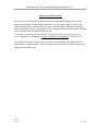
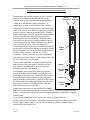
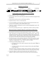
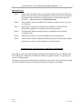
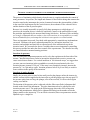
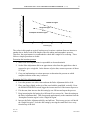
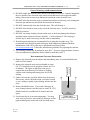
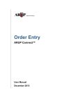
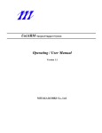
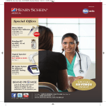
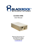
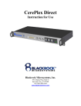
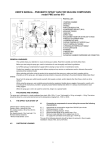
PNEUMATICALLY-ACTUATED IMPULSE ARRAY INSERTER USER MANUAL REV 1.00 391 CHIPETA WAY, SUITE G UNIVERISTY RESEARCH PARK SALT LAKE CITY, UT 84108 TEL: +1(801) 582-5533 Rev 1.00 LB-0219 March 2009 2 PNEUMATICALLY-ACTUATED IMPULSE ARRAY INSERTER (V1.00) PREFACE AND DISCLAIMER The surgical procedures that have been developed to insert the Blackrock Microsystems microelectrode arrays into the nervous system have evolved over a number of years. The method described here is the only effective way to insert the array as high-speed insertion prevents indentation of the cortical surface. The original publication on the impulse insertion process for high density microelectrode arrays is “A method for pneumatically inserting an array of penetrating electrodes into cortical tissue”, Rousche PJ, Normann RA, Annals of Biomedical Engineering, 20 (1992) 413-22. We would be interested to hear of your experiences in implanting arrays and any ideas for modifications or improvements. Unless you request otherwise, we would like to share such information with other users. Rev 1.00 LB-0219 March 2009 3 PNEUMATICALLY-ACTUATED IMPULSE ARRAY INSERTER (V1.00) OVERVIEW OF THE INSERTER SYSTEM OPERATION The pneumatically-actuated impulse inserter is designed to deliver a repeatable momentum and travel to the electrode array to allow its insertion into neural tissue. A diagram of the insertion wand is given here. A combination of compressed air and vacuum is used to control the movement of a piston mass in the shaft of the wand. The vacuum holds the mass at the top of the wand when the system is running in standby mode. When the implantation trigger is pushed, an insertion pressure pulse is delivered to the piston pressure line to propel the piston mass down to the inserter tip. When the piston mass strikes the inserter tip, it quickly transfers some of its momentum to the tip, which pushes the array into the cortex in less than 1msec. The travel distance or insertion depth of the inserter tip is mechanically limited by the spacer positioned between the tip assembly and the barrel (two spacers have been provided with the inserter: one for 1.0 mm electrodes, and one for 1.5 mm electrodes). After the insertion, a vacuum is applied to return the piston mass to the top of the inserter wand, and the tip is retracted by a weak spring, To prevent the wand from expelling air pressure pulses onto the surgical field, the inserter wand has an outer sleeve that is constantly held at vacuum at all times during the operation of the system. The adjustable air pressure in the tank of the inserter system determines the momentum transferred from the piston mass to the inserter tip. The length of the pressure pulse delivered can also be adjusted so that the piston mass is promptly retracted after a single hit of the inserter tip. Insertion pressure pulses that are too long allow the piston mass to bounce at the bottom of the wand and strike the inserter tip a second time. Sleeve Pressure Piston Pressure Piston Mass Spacer Insertion depth Inserter Tip Insertion depth During the insertion process, the wand must be rigidly held by an external apparatus such as a stereotaxic frame or a system of support bars and clamps. The quick acceleration forces on the inserter wand make it impossible to support wand by hand. To prevent accidental firing of the inserter, the system is equipped with an ENABLE/DISABLE safety button. This button is pressed to toggle the enable status of the inserter trigger, and the inserter can only be fired when the system is enabled and the ENABLE/DISABLE button is lit. Rev 1.00 LB-0219 March 2009 4 PNEUMATICALLY-ACTUATED IMPULSE ARRAY INSERTER (V1.00) ASSEMBLY OF THE WAND End piece Piston Inner tube Spacer Tip assembly Exploded diagram of the wand (outer tube or sleeve omitted). Choose either the 1.0 mm or 1.5 mm spacer. Screw the inner tube into the end of the spacer that has the shoulder and tighten firmly by hand only. Put the piston into the inner tube, small-diameter end first. Slip the outer tube or sleeve over the inner tube. Screw the manifold on to the outer tube, making sure that the ends of the tube seats securely on to the shoulder on the manifold and the spacer. Tighten the assembly by holding the outer tube by hand and gripping the spacer with the wrench provided. Screw the tip assembly into the spacer. Tighten firmly with the wrenches provided. PNEUMATIC IMPULSE INSERTER CHECKLIST AND OPERATING PROCEDURE Insure that the travel of the tip of the insertion wand is exactly 1.0 mm or 1.5 mm by using a micrometer (or an optical reticule) and a dissecting microscope. Observe the tip under the microscope, pull it out to its maximum extension, and verify this travel with the micrometer. Insure that the tip of the insertion wand is normal to the axis of the insertion wand and that it has not been bent by inappropriate handling. Check that the power switch at the back of the box is in the OFF (0) position. Attach the power cord to the control unit. Check that the correct voltage is being used (the control box is marked either 110 VAC ONLY or 220 VAC ONLY). Attach the twin flexible tubing to the wand: the long metal tube on the wand is connected to the socket marked „Piston‟ on the control box; the short metal tube on the wand is connected to the socket marked „Sleeve‟ on the control box. The flexible tubing is attached by pushing it into the red plastic connector all the way. To remove it, push the red plastic towards the control box and gently pull the tubing. Rev 1.00 LB-0219 Prepare the surgical site and rest the electrode array on the neural tissue to be implanted. Make sure that all wiring for the electrode array has been positioned. March 2009 5 PNEUMATICALLY-ACTUATED IMPULSE ARRAY INSERTER (V1.00) Position the wand with a stereotaxic device (such as a Kopf type device or a simple system made with ½-inch aluminum rods and circle clamps) to be parallel with the electrodes and centered on the electrode array. Back the inserter off of the electrode array by at least 2 mm before turning on the inserter to make sure the wand does not move and hit the array when the piston mass is initially drawn to the top of the piston. The pressure regulator on the front side of the control box is used to adjust the pressure of the compressed air, and hence the insertion force. The maximum pressure obtainable is about 30 psi. Insure the pressure reading is zero before turning on the power (If necessary, release pressure in the tank by turning the regulator counterclockwise. If there is a residual pressure in the tank, the compressor motor will not rotate and this can cause the unit to overheat.) NOTE: The pressure control regulator on the front of the instrument is unlocked by pulling the knob out and locked by pushing the knob back in. Connect the push-button trigger switch to the control box and lock the connector ring. Turn on the power switch. Dial the pressure control valve from zero up to the desired insertion pressure, and make sure the pulse adjustment control is set to the appropriate pressure pulse width for the selected insertion pressure (determination of the proper pressure and pulse width settings are discussed in the following section). Make a final check that the wand is accurately aligned over the array. Lower the wand until its tip just touches the back of the array. For cortical implants, position the wand so that it contacts the array at the peak of cortical pulsations caused by respiration and heart beats. Press the „ENABLE‟ button to activate the trigger. In a chronic implantation, carefully watch the movement of the array caused by heart pulsation and respiration. At a point when the array just touches the tip of the wand, press the trigger to make the insertion. Remove the wand from the surgical field and turn off the inserter system. Before storing the inserter, Clean the wand and tubing as needed. Unplug the twin tubing and the trigger cable. Release residual pressure in the tank by turning the pressure control valve counterclockwise until the tank pressure reaches zero. Rev 1.00 LB-0219 March 2009 6 PNEUMATICALLY-ACTUATED IMPULSE ARRAY INSERTER (V1.00) Important Notes Note 1. Before each use of the inserter, insure all the sections of the barrel and the tip of the inserter are firmly screwed together as, after repeated use, the impact of the plunger may loosen the screwed connections. Two small wrenches are provided . . . take care not to over tighten the threads. Note 2. Do not run the unit for more than 30-40 minutes at a time in order to prevent over-heating. Note 3. No warranty is expressed or implied and no liability is assumed for the information, suggestions, and surgical procedures given here. Note 4. The Pneumatic Impulse Insertion System is intended for use in animal experiments only. Note 5. Make sure the wand is correctly assembled (see the details above). Note 6. Ensure that the wand is rigidly held during insertion or else the impact during insertion may cause it to twist and make a skewed insertion. STERILIZATION AND CLEANING OF THE WAND AND TRIGGER The stainless steel wand and flexible twin tubing may be sterilized by heat or ethylene oxide. The wand can be cleaned with a mild bleach solution, enzymatic cleaners, or any other noncorrosive cleaning agents. The trigger switch can be sterilized only with ethylene oxide, and it can be cleaned by wiping it with a mild bleach solution or mild soap solution; don‟t immerse it in liquids. Rev 1.00 LB-0219 March 2009 7 PNEUMATICALLY-ACTUATED IMPULSE ARRAY INSERTER (V1.00) CONTROL OF IMPACT INSERTION AND INSERTER CALIBRATION PROCEDURE The process of implanting a high density electrode array is complex and under the control of many parameters: air pressure, the length and diameter of the flexible tubing that connects the insertion wand to the instrument, the precise clearances between the piston and the cylinder in the wand, the load imposed by the cortical tissues, the mechanics of the solenoid valves and the duration of the air pressure pulse. Because it is virtually impossible to specify fully these parameters to a high degree of precision, the insertion process is basically empirically „tuned‟ to the particular device and the particular application by the neuroscientist using each device. Because of this variability, we strongly recommend that you conduct a few trial insertions in an expendable or recently deceased animal before you attempt the insertion in an expensive or trained animal. These are important issues and, if not dealt with appropriately, unsatisfactory implantations can result. Problems with poorly adjusted parameters are: incomplete insertion, over insertion, and multiple insertions due to repeated recoil of the mechanical stop in the insertion wand. We present below the two variables that are most important in controlling this process and that are under the direct control of the experimenter. We describe how they are controlled and recommend starting positions. Insertion air pressure This is a particularly important parameter and is set by the regulator on the front side of the inserter. Insufficient pressure results in incomplete insertion and excessive pressure can cause cortical tissue trauma. For cortical insertions of 100-electrode arrays, we suggest that you start your test insertions in the expendable or recently deceased animal with a low insertion pressure (around 15-20 psi). If the array is not completely inserted, increase the pressure by 3 to 5 psi and try again. Insertion pressures below 10 psi are likely to result in some variation in the quality of the insertions. Insertion air pulse duration Ideally, the pressure pulse is timed to last until just after the plunger strikes the inserter tip, and the vacuum is then reapplied to the inner tube to pull the plunger up to the top again. If the pressure pulse lasts too long, the plunger, after it has recoiled, it is driven down again causing a second hit. The duration of the pressure pulse is adjusted with the fifteen turn Pulse Adjustment dial located on the front of the instrument. The pulse duration needs to be adjusted for each insertion pressure used. The graph on the following page shows the effect of insertion pressure and potentiometer setting (Pulse Adjustment Setting) on the number of hits the plunger makes on the inserter tip. For an effective insertion, these two parameters must be adjusted to give a single hit. Rev 1.00 LB-0219 March 2009 8 PNEUMATICALLY-ACTUATED IMPULSE ARRAY INSERTER (V1.00) Pulse Adjustment Setting 5 4 Double hit region 3 Single hit region 2 Incomplete insertion region 1 0 5 10 15 20 25 30 Pressure [psi] The values in this graph are typical, but there may be minor variations from one inserter to another due to factors such as the length of the twin tubing and atmospheric pressure. Therefore, the experimenter is recommended to check that a single hit is occurring. There follows a simple procedure to do this. Determine the insertion pressure 1. Make some trial implantations in expendable or deceased animals. 2. Set the Pulse Adjustment dial to an approximate value from the graph above that is expected to give a single hit. In the absence of prior data, assume a pressure of about 15-20 psi. 3. Carry out implantations at various pressures to determine the pressure at which complete insertion of the array is assured. Determine the Pulse Adjustment setting 4. Leave the pressure set at this value and turn the Pulse Adjustment dial to 0.00. 5. Place your finger lightly on the tip of the wand with the wand held vertically. Press the ENABLE/DISABLE switch, trigger the inserter and feel if the inserter tip moves. 6. If it does not, then increase the dial setting by one full turn and repeat the process 7. Keep increasing the dial setting by a full turn till you sense a hit. Note the setting on the Pulse Adjustment dial. This corresponds approximately to the transition from the „Incomplete insertion region‟ to the „Single hit region‟. 8. Increase the Pulse Adjustment dial by one half turn. This insures you are well inside the „Single hit region‟. Lock the dial setting by moving the small black lever away from the top of the dial. Rev 1.00 LB-0219 March 2009 9 PNEUMATICALLY-ACTUATED IMPULSE ARRAY INSERTER (V1.00) 9. Repeat the dummy implantation to the insertion pressure is still optimal. If you make changes to the inserter— for example, you replace or shorten the twin tubing that connects the insert control box to the wand—or if you use an array with a different number of electrodes, you should check the calibration of the system Reuse of electrode arrays Microelectrode Arrays used in acute experiment can be reused with proper care and cleaning. We do not find it practical to reuse arrays used from chronic experiments due to the polymers and cements used during initial implantation. Acute electrode assemblies from Blackrock Microsystems can be re-used for an average of 5 to 10 experiments and sometimes more with proper cleaning and storage between experiments. Suggested cleaning practices are summarized on the following page: Rev 1.00 LB-0219 March 2009 10 PNEUMATICALLY-ACTUATED IMPULSE ARRAY INSERTER (V1.00) General Warnings and Recommendations DO NOT handle the electrode array directly with fingers or tweezers. Instead, manipulate the wire bundle of the electrode array with tweezers that have been wrapped in rubber tubing. Bare metal tweezers may damage the insulation on the electrode wires. DO NOT allow the electrode to tap or contact hard surfaces as this may crack, damage the electrode tips and this may also break the electrodes in the array. DO NOT ultrasonically clean the electrode array. This will destroy it. DO NOT allow blood or tissue to dry out on the electrode array. It will be extremely difficult to remove. DO NOT use strong cleaning solvents on the array as these may damage the polymer insulation on the electrode and wire assembly. A weak solution of <20% isopropyl alcohol may be used if necessary, but this is not recommended. Weak detergent solutions are recommended for cleaning the electrode array. We recommend using Enzol Enzymatic Detergent from Johnson and Johnson (Medical Manufacturer code #2254), this may be purchased from Henry Schein (www.henryschein.com). Follow the manufacturer guidelines for preparing the solution. The cleaning solution may be warmed to up to 60ºC. If you are using enzymatic cleaners, refer to manufacturers guidelines (Enzol cannot be used above 40ºC). RECOMMENDED CLEANING PROCEDURE 1) Remove the electrode from the subject and immediately place it in clean distilled water until it will be cleaned. Acute Connector 2) Immerse the electrode array and wire bundle in warm (30-35ºC) distilled water or enzymatic cleaner for 15 to 60 minutes. The figure at right shows one way to suspend the electrode array in a beaker of cleaning solution with a heating and stirring plate for SLOW stirring. 3) Under a microscope, check for debris stuck in the array. If necessary, remove the debris with a soft artist‟s brush or use a syringe to gently squirt cleaning solution into the array. 4) Rinse with distilled water. If you used a detergent in your cleaning solution, soak the array in warm (30-35ºC) distilled water for an additional 30 minutes and rinse again. 5) Let the array dry in air at room temperature. You may wick away excess rinse water with soft Kimwipe or filter paper touched gently to the side of the electrode array. Rev 1.00 LB-0219 Mixer Heater and/or magnetic stirring plate March 2009