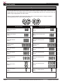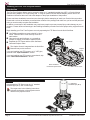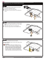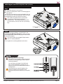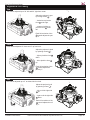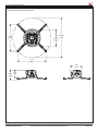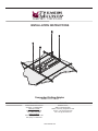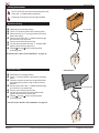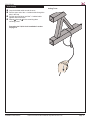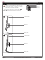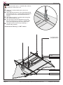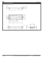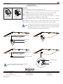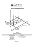
1
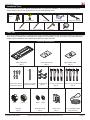
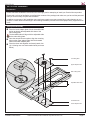
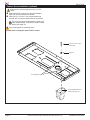
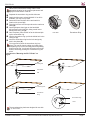
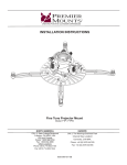
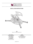
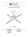
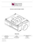
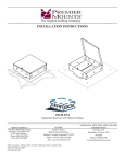
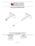
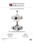
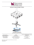
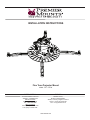
INSTALLATION INSTRUCTIONS Fine Tune Projector Mount Model: FTP / FTPW NORTH AMERICA 3130 East Miraloma Avenue Anaheim, CA 92806 USA USA and Canada Phone: 1.800.368.9700 Fax: 1.800.832.4888 Other Locations Phone: (001).714.632.7100 Fax: (001).714.632.1044 EUROPE Swallow House, Shilton Industrial Estate, Shilton, Coventry, England CV79JY Phone: +44 (0) 2476 614700 Fax: +44 (0) 2476 614710 9530-090-001-08 Fine Tune Projector Mount Contents Weight Limit............................................................................................................................................................... 2 Warning Statements.................................................................................................................................................. 2 Installation Tools........................................................................................................................................................ 3 Parts List................................................................................................................................................................... 3 Mounting Hardware................................................................................................................................................... 4 Lock-It™ Security Hardware Pack............................................................................................................................ 4 Features.................................................................................................................................................................... 5 Installing the Fine Tune Projector Mount................................................................................................................... 6 Introduction................................................................................................................................................... 6 Pipe Installation............................................................................................................................................ 6 Wood Stud Installation.................................................................................................................................. 8 Attaching the Universal Projector Plate................................................................................................................... 10 Selecting the Mounting Hardware.............................................................................................................. 10 Multiple Mount Point Installation................................................................................................................. 11 Single Mount Point Installation................................................................................................................... 13 Securing the Quick Set Base.................................................................................................................................. 14 Attaching the Projector to the Mount....................................................................................................................... 14 Alignment & Fine-Tuning......................................................................................................................................... 15 Locking in the Adjustments...................................................................................................................................... 16 Securing the Fine Tune Projector Mount................................................................................................................. 16 Technical Specifications.......................................................................................................................................... 17 Warranty.................................................................................................................................................................. 18 Disclaimer................................................................................................................................................................ 18 Weight Limit Maximum Projector Weight: 65 lbs. THE CEILING STRUCTURE MUST BE CAPABLE OF SUPPORTING AT LEAST FIVE TIMES THE WEIGHT OF THE PROJECTOR. IF NOT, THE CEILING STRUCTURE MUST BE REINFORCED. Warning Statements PRIOR TO THE INSTALLATION OF THIS PRODUCT, THE INSTALLATION INSTRUCTIONS MUST BE READ AND COMPLETELY UNDERSTOOD. KEEP THESE INSTALLATION INSTRUCTIONS IN AN EASILY ACCESSIBLE LOCATION FOR FUTURE REFERENCE. PROPER INSTALLATION PROCEDURE BY A QUALIFIED SERVICE TECHNICIAN MUST BE FOLLOWED, AS OUTLINED IN THESE INSTALLATION INSTRUCTIONS. FAILURE TO DO SO COULD RESULT IN PROPERTY DAMAGE, SERIOUS PERSONAL INJURY, OR EVEN DEATH. SAFETY MEASURES MUST BE PRACTICED AT ALL TIMES DURING THE ASSEMBLY OF THIS PRODUCT. USE PROPER SAFETY EQUIPMENT AND TOOLS FOR THE ASSEMBLY PROCEDURE TO PREVENT PERSONAL INJURY. PREMIER MOUNTS DOES NOT WARRANT AGAINST DAMAGE CAUSED BY THE USE OF ANY PREMIER MOUNTS PRODUCT FOR PURPOSES OTHER THAN THOSE FOR WHICH IT WAS DESIGNED OR DAMAGE CAUSED BY UNAUTHORIZED ATTACHMENTS OR MODIFICATIONS, AND IS NOT RESPONSIBLE FOR ANY DAMAGES, CLAIMS, DEMANDS, SUITS, ACTIONS OR CAUSES OF ACTION OF WHATEVER KIND RESULTING FROM, ARISING OUT OF OR IN ANY MANNER RELATING TO ANY SUCH USE, ATTACHMENTS OR MODIFICATIONS. At least two qualified people should perform the assembly procedure. Personal injury and/or property damage can result from dropping or mishandling the projector. If mounting to wall studs or ceiling studs, make sure that the mounting screws are anchored into the center of the wall studs or ceiling studs. Use of an edge-to-edge stud finder is recommended. Be aware of the mounting environment. If drilling and/or cutting into the mounting surface, always make sure that there are no electrical wires in wall. Cutting or drilling into an electrical line may cause serious personal injury. Make sure there are no water or natural gas lines inside the wall where the mount is to be located. Cutting or drilling into a water or gas line may cause severe property damage or personal injury. This product is intended for indoor use only. Use of this product outdoors could lead to product failure and/or serious personal injury. Do not install near sources of high heat. Do not install on a structure that is prone to vibration, movement or chance of impact. Contact Premier Mounts with any questions: (800) 368-9700 [email protected] Page 2 Visit the Premier Mounts website at http://www.mounts.com Installation Instructions Fine Tune Projector Mount Installation Tools The following tools may be required depending upon your particular installation. They are not included.. Electronic Stud Finder Hand Held Drill Pencil Protective Eyewear Phillips Tip Screwdriver 2 1 Socket Wrench Socket Wrench Extension ⅛˝ Wood Drill Bit Ladder Tape Measure Parts List Make sure your Premier Mounts product has the following hardware and components before beginning installation. If there are parts missing and/or damaged, stop the installation and call Premier Mounts at (800) 368-9700. Fine Tune Projector Mount Hardware FTP Dome (Qty 1) Quick Set Base (Qty 1) Universal Projector Plate (Qty 1) Mounting Legs - Short (Qty 2) Mounting Legs - Long (pre-installed) (Qty 4) Barrel Caps (Qty 8) Fine Tune Projector Base Box Mounting Hardware #14 x 3˝ Wood Screws (Qty 2) M5 Allen Wrench (Qty 1) M6 x 6mm Security Set Screw (Qty 1) Installation Instructions M3 Security Allen Wrench (Qty 1) M6 x 8mm Security Screw (Qty 4) Installation Disk (Qty 1) M5 x 12mm Security Screw (Qty 1) Visit the Premier Mounts website at http://www.mounts.com Page 3 Fine Tune Projector Mount Parts List (cont’d) Mounting Hardware Lock-It™ Security Hardware Pack Your Premier Mounts Fine Tune Projector Mount comes with the option of using Lock-It™ Security Screws. Simply replace any of the Phillips head screws with the corresponding sized Lock-It™ Security Screws and tighten using the appropriate size Allen wrench. When you see the graphics below associated with a step, you have the option of using the standard mounting hardware or the Lock-It Security hardware. Standard Hardware Page 4 Lock-It™ Security Hardware M2.5 x 10mm Screw (Qty 4) M2.5 x 10mm Security Screw (Qty 4) M2.5 x 12mm Screw (Qty 4) M2.5 x 12mm Security Screw (Qty 4) M3 x 16mm Screw (Qty 4) M3 x 16mm Security Screw (Qty 4) M3 Flat Washer (Qty 10) M3 Flat Washer (Qty 10) M4 x 10mm Screw (Qty 4) M4 x 10mm Security Screw (Qty 4) M4 x 12mm Screw (Qty 4) M4 x 12mm Security Screw (Qty 4) M5 x 12mm Screw (Qty 4) M5 x 12mm Security Screw (Qty 4) M6 x 12mm Screw (Qty 4) M6 x 12mm Security Screw (Qty 8) ¼-20 x 5/16″ Screw (Qty 1) ¼-20 x 5/16″ Security Screw (Qty 1) Visit the Premier Mounts website at http://www.mounts.com Installation Instructions Fine Tune Projector Mount Features Multiple Mounting Options You can install your Fine Tune Projector mount to 1½˝ NPT pipe or a ceiling stud. Lock-It™ Security Hardware Protect your projector by installing specialized hardware at critical mounting points. Mounting Legs Both long and short mounting legs, combined with the numerous Universal Projector Plate Mounting Slots, allow for near infinite mount configurations. Mounting Slots Allows you to choose from a variety of mounting options and projector mount-point configurations. Installation Disk Versatile tool allows you to rapidly install your Fine Tune Projector mount on to 1½˝ NPT pipe by using a socket wrench and socket wrench extension, or you can use it as a mounting bracket for ceiling stud installation. Adjustable Leveling Barrels You can quickly level the mounting legs without any specialized tools. Fine-Tune Controls Without needing any tools to loosen mounting hardware, you can adjust: Roll up to 5˚ to either side. Pitch up to 15˚ down and 5˚ up. Yaw up to 20˚ left and right. Security Leveling Barrel Allows the user to easily secure the mount with a padlock or a steel-cable locking system (PCB-CSL1). The locks (sold separately) would make it nearly impossible for anyone to remove the projector from the mount. Projector Direction Arrows Inscribed on the underside of the FTP Dome and on the top of the Quick Set Base, you can always know for certain which way your projector will be pointing while you are installing your Fine-Tune Projector mount. Quick Set Base If your projector ever needs service, you can quickly detach and attach it without having to uninstall the entire mount or re-align the projector to the screen. Installation Instructions Visit the Premier Mounts website at http://www.mounts.com Page 5 Fine Tune Projector Mount Installing the Fine Tune Projector Mount Introduction The Fine Tune Projector Mount may be secured to either a 1½˝ standard threaded pipe (NPT), a Premier Mounts optional ceiling adapter, or a single ceiling stud. If using an optional Premier Mounts adapter, please refer to the installation instructions that come with each adapter on the proper installation of that product. Please read these installation instructions once thoroughly before attempting to install your Premier Mounts product. Please take a minute to familiarize yourself with the contents of the package and make sure you have all the parts and tools you need to safely complete the installation. In addition, some steps of this installation may require two people to prevent personal injury and/or damage to your projector. Please observe all warnings in the following installation procedure and utilize proper safety equipment at all times. Begin installing your Fine Tune Projector mount by separating the FTP Dome from the Quick Set Base. Use Phillips screwdriver to remove the M5 x 12mm ®® ¯¯ screw. Place the M5 x 12mm Security Screw in a safe location. Use your thumb and forefinger, or a screwdriver (Phillips or slotted), to loosen the Captive Screw. Separate the FTP Dome and the Quick Set Base / Universal Projector Plate. FTP Dome The Captive Screw is integrated into the Quick Set Base and may not be removed. Captive Screw If you are installing your FTP mount to a 1½˝ NPT pipe, proceed to the “Pipe Installation” section. If you are installing your FTP mount to a wood stud, skip to the “Wood Stud Installation” section. Quick Set Base / Universal Projector Plate M5 x 12mm Screw Pipe Installation Step 1 Hand-thread the FTP Dome onto the 1½˝ standard threaded pipe (NPT) until it is hand-tight. 1½˝ Standard Threaded Pipe (NPT) The target arrow in the following instructions indicates the direction of the projector screen relative to the projector mount. Page 6 Visit the Premier Mounts website at http://www.mounts.com Installation Instructions Fine Tune Projector Mount Installing the Fine Tune Projector Mount (cont’d) Step 2 Attach a 6˝ or longer socket wrench extension onto a socket wrench. ®® Insert the end of the socket wrench extension into the center of the Installation Disk, then insert the Installation Disk into the underside of the FTP Dome. Note the arrow inscribed inside of the FTP Dome. Inscribed Arrow FTP Dome as Viewed from Below Step 3 Tighten the FTP Dome until the inscribed arrow on the underside of the FTP Dome points in the direction in which the projector will be facing. If the FTP Dome becomes too tight to turn and the inscribed arrow is pointing away from the projector screen by more than 5˚, loosen the FTP Dome one (1) rotation until the inscribed arrow points towards the projector screen. The “Alignment & Fine-Tuning” section of this manual describes how you can fine-tune the roll, pitch, and yaw of the projector. Remove the Installation Disk and store it in a safe location. Step 4 Secure the FTP Dome to the pipe with one (1) M6 x 6mm set screw and tighten it using the M3 Allen wrench. You can use either the standard hardware or Lock-It™ security hardware. Proceed to the “Attaching the Universal Projector Plate” section. Installation Instructions Visit the Premier Mounts website at http://www.mounts.com Page 7 Fine Tune Projector Mount Installing the Fine Tune Projector Mount (cont’d) Wood Stud Installation Step 1 Use a stud finder to locate a ceiling stud closest to ®® ¯¯ your desired installation location. Identify the center of the ceiling stud. Use a pencil to mark the location of the ceiling stud center. CeStud nte r Step 2 Place the Installation Disk against the ceiling with the ®® mounting holes aligned with the center of the ceiling stud. Use a pencil and mark two (2) mounting hole locations through the holes in the Installation Disk. Step 3 Remove the Installation Disk and set it aside. Drill a pilot hole in the center of each mark using a power drill and 1/8˝ drill bit. Pilot Holes When a screw is driven into a material, such as wood, it can act as a wedge, generating outward pressure which can cause many materials to split. Drilling a small pilot hole in the material into which the screw will be driven causes less ‘wedging’ to take place, thereby reducing the likelihood of the material being split. It also reduces the possibility of the screw head from being sheared off by torque. Page 8 Visit the Premier Mounts website at http://www.mounts.com Installation Instructions Fine Tune Projector Mount Installing the Fine Tune Projector Mount (cont’d) Step 4 Insert the Installation Disk into the underside of the FTP Dome. Note the arrow inscribed inside of the FTP Dome; make sure that it is pointed in the same direction that your projector will be pointed. Inscribed Arrow FTP Dome as Viewed from Below Step 5 Insert one (1) #14 x 3˝ screw through each of the holes in the bottom of the Installation Disk and into the pilot ®® holes. Tighten each screw until the FTP Dome and Installation Disk are secure against the ceiling. Do not overtighten the mounting screws. Proceed to the “Attaching the Universal Projector Plate” section. Installation Instructions Visit the Premier Mounts website at http://www.mounts.com Page 9 Fine Tune Projector Mount Attaching the Universal Projector Plate Selecting the Mounting Hardware Insert a small straw or toothpick into the threaded ®® ¯¯ °° ±± inserts found on the bottom or top of the projector. Use a pencil to mark the depth of the threaded insert on the small straw or toothpick. Mark the straw or toothpick 1/8” above the depth of the threaded insert, as shown in Figure 1. Insert the small straw or toothpick into the remaining threaded inserts to compare and verify their depth using the straw or toothpick’s 1/8” allowance mark. Locate the correct diameter screw for the threaded insert. If the screw you selected is longer than the 1/8” allowance mark on the small straw or toothpick, as shown in Figure 2 and Figure 3, do not use this screw. The screw length must not bypass the mark. Marking the 1/8” Allowance ²² Test each size of the screws provided. Small Straw or Toothpick The correct screws should thread easily into the mounting point and not pull out when tension is applied. Does your projector have multiple mount points or a single mount point? If your projector has multiple mount points, proceed to the “Multiple Mount Point Installation” section. Small Straw or Toothpick Depth Plus 1/8” Allowance Mark Small Straw or Toothpick Depth Plus 1/8” Allowance Mark If your projector has a single mount point, remove the pre-installed mounting legs on the universal projector plate and skip to the “Single Mount Point Installation” section. Page 10 Visit the Premier Mounts website at http://www.mounts.com Installation Instructions Fine Tune Projector Mount Attaching the Universal Projector Plate (cont’d) Multiple Mount Point Installation Step 1 Locate the projector’s mount points. ®® Position an appropriate number of mounting legs on the projector. The four long mounting legs come pre-installed, but you can use three (3) or four (4) long and/or short mounting legs depending on what your projector requires. The number and placement of mount points on projectors varies between projector manufacturers. This example projector has five (5) mount points, but only uses four (4) mounting legs. Projector plate not shown Step 2 Insert the mounting hardware, as determined in the “Selecting the Mounting Hardware” section, through the leveling barrels of the mounting legs into the thread insert of the projector. You can use either the standard Phillips head or Lock-It™ security hardware. Do not tighten the mounting hardware at this time. Mounting Hardware Too Long? The depth of some projector mount points may prevent you from tightening the M2.5 and M3 mounting hardware. You can reduce the length of the M2.5 and M3 mounting hardware by stacking up to a maximum of five (5) M3 flat washers inside the leveling barrel. Avoid stacking too many M3 washers; the mounting hardware must thread into the projector mount point at least four (4) complete turns. Installation Instructions Visit the Premier Mounts website at http://www.mounts.com Page 11 Fine Tune Projector Mount Attaching the Universal Projector Plate (cont’d) Step 3 Raise or lower each of the mounting legs, by rotating the leveling barrels, until all of the mounting legs are at an equal height. •Lower the mounting leg by rotating the leveling barrel counter-clockwise. •Raise the mounting legs by rotating the leveling barrel clockwise. Step 4 Identify the projector’s approximate front-to-back ®® ¯¯ center of gravity. Place your hands on each side of the projector and gently lift it an inch from the surface on which it is resting. Carefully adjust your grip on the projector until it seems balanced from front-to-back. Mentally note the apparent center of gravity. Identify the projector’s approximate side-to-side center of gravity. Place your hands on the front and back of the projector and gently lift it an inch from the surface on which it is resting. Carefully adjust your grip on the projector until it seems balanced from side-to-side. Mentally note the apparent center of gravity. Place the Universal Projector Plate (if not already attached) on top of the mounting legs with the center hole as close as possible to the projector’s center of gravity. Side-to-Side Center of Gravity Front-to-Back Center of Gravity Step 5 Verify that the mounting legs are at an equal height. ®® Return to Step 3 if they are not at an equal height or the Universal Projector Plate is not level. Verify the position of the integrated sliding M6 square nut in the mounting leg relative to a nearby slot on the Universal Projector Plate. If the M6 square nut is not aligned with any slot, you can use any thin implement, such as a toothpick, to nudge it into alignment. Page 12 Visit the Premier Mounts website at http://www.mounts.com Sliding M6 Square Nut Installation Instructions Fine Tune Projector Mount Attaching the Universal Projector Plate (cont’d) Step 6 Tighten the mounting screws to the projector. Do not overtighten the mounting screws. Step 7 Attach the Universal Projector Plate (if not already attached) to each of the mounting legs by inserting and tightening one (1) M6 x 12mm screw through the Universal Projector Plate into the M6 square nut on each of the mounting legs. Do not overtighten the mounting screws. You can use either the standard Phillips head or Lock-It™ security hardware. ®® Insert one (1) Barrel Cap into the end of each leveling barrel (except the security leveling barrel). Proceed to the “Securing the Quick Set Base” section. Single Mount Point Installation A single ¼-20 x 5/16″ screw must be used to attach the Universal Projector Plate to the projector if your projector has only one mounting point. Do not overtighten the mounting screws. You can use either the standard Phillips head or Lock-It™ security hardware. Proceed to the “Securing the Quick Set Base” section. Installation Instructions Visit the Premier Mounts website at http://www.mounts.com Page 13 Fine Tune Projector Mount Securing the Quick Set Base You had the option of installing Lock-It™ security hardware during several of the previous steps. You may also exchange the screws which secure the Universal Projector Plate to the Quick Set Base. Remove the four (4) Phillips head M6 x 8mm screws ®® ¯¯ which secure the Quick Set Base to the Universal Projector Plate. Replace each M6 x 8mm Phillips head screw with one (1) M6 x 8mm Security screw. Tighten all screws. Do not overtighten the mounting screws. Proceed to the “Attaching the Projector to the Mount” section. Attaching the Projector to the Mount If your projector is heavy and/or bulky, two people may be required to safely attach your projector to the FTP Dome. If your projector is to be mounted higher than shoulder height, you may need to use one or more ladders to safely attach your projector to the FTP Dome. Verify that the FTP Dome is in the factory-default position prior to attempting to attach the Quick Set Base/ projector assembly. Serious damage to property or severe personal injury could occur if the FTP Dome is not at the factory-set position. Raise the projector (with the Quick Set Base and Universal Projector Plate securely attached) and slide the Quick ®® ¯¯ Set Base onto the FTP Dome. Do not release the projector. Use your thumb and forefinger to thread the Captive Screw into the FTP Dome until it is hand-tight. Insert the M5 x 12mm screw into the location shown and tighten it using a Phillips screwdriver. You can use either the standard Phillips head or Lock-It™ security hardware. Do not overtighten the M5 x 12mm screw. Proceed to the “Alignment & Fine-Tuning” section. Captive Screw Page 14 Visit the Premier Mounts website at http://www.mounts.com Installation Instructions Fine Tune Projector Mount Alignment & Fine-Tuning Yaw Yaw can be adjusted up to 20° left and 20° right from center. Adjust the projector’s yaw by turning control ... ...clockwise to pivot the front to the right. ...counter-clockwise to pivot the front to the left. Each full revolution of the control adjusts the yaw by 4°. Pitch Pitch can be adjusted 15° down and 5° up from level. Adjust the projector’s pitch by spinning control ... ...right to pitch the front down. ...left to pitch the front up. Each full revolution of the control adjusts the pitch by 1°. Roll Roll can be adjusted up to 5˚ to either side from level. Adjust the projector’s roll by spinning control ... ...left to roll the right side up. ...right to roll the right side down. Each full revolution of the control adjusts the roll by 1°. Installation Instructions Visit the Premier Mounts website at http://www.mounts.com Page 15 Fine Tune Projector Mount Locking in the Adjustments After you have finalized your yaw, pitch, and roll adjustments, you can lock them in to prevent them from being accidentally changed. FTP Support Sphere Finger-tighten the knurl knob until it makes firm contact with the FTP Support Sphere (Figure 1). The M6 set screw on the front of the FTP Dome provides tension for the roll, pitch and yaw adjustments. This is a factory setting which you should not change (Figure 2). Figure 1 Figure 2 Securing the Fine Tune Projector Mount Your FTP mount includes one pre-installed Security Leveling Barrel in a mounting leg which can provide additional theft deterrence for your projector. Shown below is an example of how you can route a PCB-CSL1 Security Cable through the Security Barrel. The Security Cable is routed through the Security Barrel after the standard leveling barrel is replaced by the Security Barrel and the projector mount is securely attached to the projector as per the installation instructions. The PCB-CSL1 kit also includes a Cable Looper which you can use to create a tight loop for cable management. The PCB-CSL1 kit, which contains one (1) 18" braided cable, one (1) chassis sleeve, one (1) cable looper, one (1) cylinder lock, and two (2) cylinder lock keys, is sold separately. Additional cylinder locks, additional Security Barrels, and longer cables are also sold separately. Page 16 Visit the Premier Mounts website at http://www.mounts.com Installation Instructions Fine Tune Projector Mount Technical Specifications All measurements are in inches [mm]. 11.09 [282] ø 6.94 [176] ø 16.43 [417] 12.12 [308] 4.76 [121] 4.05 [103] 3.28 [83] Installation Instructions Visit the Premier Mounts website at http://www.mounts.com Page 17 Fine Tune Projector Mount Warranty PREMIER MOUNTS LIMITED LIFETIME WARRANTY What and Who is Covered by this Limited Warranty and for How Long Premier Mounts warrants this product to be free from defects in material and workmanship for the lifetime of the original owner of this product. The limited warranty is valid only for the original purchaser of the product. What Premier Mounts Will Do At the sole option of Premier Mounts, Premier Mounts will repair or replace any product or product part that is defective. If Premier Mounts chooses to replace a defective product or part, a replacement product or part will be shipped to you at no charge, but you must pay any labor costs. What is Not Covered; Limitations PREMIER MOUNTS DISCLAIMS ANY LIABILITY FOR DAMAGE TO MOUNTS, ADAPTERS, DISPLAYS, PROJECTORS, OTHER PROPERTY, OR PERSONAL INJURY RESULTING, IN WHOLE OR IN PART, FROM IMPROPER INSTALLATION, MODIFICATION, USE OR MISUSE OF ITS PRODUCTS. PREMIER MOUNTS DISCLAIMS ALL OTHER WARRANTIES, EXPRESS OR IMPLIED, INCLUDING WARRANTIES OF MERCHANTABILITY AND FITNESS FOR A PARTICULAR PURPOSE. PREMIER MOUNTS IS NOT RESPONSIBLE FOR INCIDENTAL OR CONSEQUENTIAL DAMAGES, INCLUDING BUT NOT LIMITED TO, INABILITY TO USE ITS PRODUCTS OR LABOR COSTS FOR REMOVING AND REPLACING DEFECTIVE PRODUCTS OR PARTS. SOME STATES DO NOT ALLOW THE EXCLUSION OR LIMITATION OF INCIDENTAL OR CONSEQUENTIAL DAMAGES, SO THE ABOVE LIMITATION OR EXCLUSION MAY NOT APPLY TO YOU. What Customers Must Do for Limited Warranty Service If you discover a problem that you think may be covered by the warranty you MUST REPORT it in writing to the address below within thirty (30) days. Proof of purchase (an original sales receipt) from the original consumer purchaser must accompany all warranty claims. Warranty claims must also include a description of the problem, the purchaser’s name, address, and telephone number. General inquiries can be addressed to Premier Mounts Customer Service at 1-800368-9700. Warranty claims will not be accepted over the phone or by fax. Premier Mounts Attn: Warranty Claim 3130 East Miraloma Ave. Anaheim, CA 92806 How State Law Applies THIS WARRANTY GIVES YOU SPECIFIC LEGAL RIGHTS, AND YOU MAY ALSO HAVE OTHER RIGHTS WHICH VARY FROM STATE TO STATE. Disclaimer Premier Mounts intends to make this manual accurate and complete. However, Premier Mounts makes no claim that the information contained herein covers all details, conditions or variations, nor does it provide for every possible contingency in connection with the installation or use of this product. The information contained in this document is subject to change without notice or obligation of any kind. Premier Mounts makes no representation of warranty, expressed or implied, regarding the information contained herein. Premier Mounts assumes no responsibility for accuracy, completeness or sufficiency of the information contained in this document. ©Premier Mounts 2010 Page 18 Visit the Premier Mounts website at http://www.mounts.com Installation Instructions INSTALLATION INSTRUCTIONS Suspended Ceiling Adapter Model: PP-FCTA-QL NORTH AMERICA 3130 East Miraloma Avenue Anaheim, CA 92806 USA USA and Canada Phone: (800) 368-9700 Fax: (800) 832-4888 Other Locations Phone: (001) 714-632-7100 Fax: (001) 714-632-1044 EUROPE Swallow House, Shilton Industrial Estate, Shilton, Coventry, England CV79JY Phone: +44 (0) 2476 614700 Fax: +44 (0) 2476 614710 9533-030-001-06 PP-FCTA-QL Contents Weight Limit...................................................................................................................................................................... 2 Warning Statements......................................................................................................................................................... 2 Installation Tools............................................................................................................................................................... 3 Parts List.......................................................................................................................................................................... 3 Features........................................................................................................................................................................... 4 PP-FCTA-QL Installation.................................................................................................................................................. 5 Camera Screw Installation (optional)............................................................................................................................... 6 Cutting the Access Hole................................................................................................................................................... 7 Mounting the PP-FCTA-QL............................................................................................................................................... 8 Securing the Ceiling Plate................................................................................................................................................ 9 Electrical Box Cut-out Removal........................................................................................................................................ 9 Ceiling Attachment......................................................................................................................................................... 10 Quick Lock Installation................................................................................................................................................... 12 Securing 1 ½˝ NPT to the PP-FCTA-QL......................................................................................................................... 15 Securing the Camera (optional)..................................................................................................................................... 15 Technical Specifications................................................................................................................................................. 16 Warranty......................................................................................................................................................................... 17 Disclaimer....................................................................................................................................................................... 17 Weight Limit Maximum Projector Weight: 50 lbs. THE CEILING STRUCTURE MUST BE CAPABLE OF SUPPORTING AT LEAST FIVE TIMES THE WEIGHT OF THE PROJECTOR. IF NOT, THE CEILING STRUCTURE MUST BE REINFORCED. Warning Statements PRIOR TO THE INSTALLATION OF THIS PRODUCT, THE INSTALLATION INSTRUCTIONS MUST BE READ AND COMPLETELY UNDERSTOOD. KEEP THESE INSTALLATION INSTRUCTIONS IN AN EASILY ACCESSIBLE LOCATION FOR FUTURE REFERENCE. PROPER INSTALLATION PROCEDURE BY A QUALIFIED SERVICE TECHNICIAN MUST BE FOLLOWED, AS OUTLINED IN THESE INSTALLATION INSTRUCTIONS. FAILURE TO DO SO COULD RESULT IN PROPERTY DAMAGE, SERIOUS PERSONAL INJURY, OR EVEN DEATH. SAFETY MEASURES MUST BE PRACTICED AT ALL TIMES DURING THE ASSEMBLY OF THIS PRODUCT. USE PROPER SAFETY EQUIPMENT AND TOOLS FOR THE ASSEMBLY PROCEDURE TO PREVENT PERSONAL INJURY. PREMIER MOUNTS DOES NOT WARRANT AGAINST DAMAGE CAUSED BY THE USE OF ANY PREMIER MOUNTS PRODUCT FOR PURPOSES OTHER THAN THOSE FOR WHICH IT WAS DESIGNED OR DAMAGE CAUSED BY UNAUTHORIZED ATTACHMENTS OR MODIFICATIONS, AND IS NOT RESPONSIBLE FOR ANY DAMAGES, CLAIMS, DEMANDS, SUITS, ACTIONS OR CAUSES OF ACTION OF WHATEVER KIND RESULTING FROM, ARISING OUT OF OR IN ANY MANNER RELATING TO ANY SUCH USE, ATTACHMENTS OR MODIFICATIONS. At least two qualified people should perform the assembly procedure. Personal injury and/or property damage can result from dropping or mishandling the projector. This product is intended for indoor use only. Use of this product outdoors could lead to product failure and/or serious personal injury. Do not install near sources of high heat. Do not install on a structure that is prone to vibration, movement or chance of impact. Contact Premier Mounts with any questions: (800) 368-9700 [email protected] Page 2 Visit the Premier Mounts website at http://www.mounts.com Installation Instructions PP-FCTA-QL Installation Tools The following tools may be required, dependent upon your particular installation. These tools are not provided by Premier Mounts, but you can purchase them at your local hardware store. Ladder Hand Held Drill 1/8˝ Drill Bit Pencil 1/4” Concrete Drill Bit Phillips Tip Screwdriver Protective Eyewear Hammer Hole Saw Parts List Your Premier Mounts product is shipped with all proper installation hardware and components. Make sure that none of these parts are missing and/or damaged before beginning the installation. If there are parts missing and/or damaged, please stop the installation and contact Premier Mounts at (800) 368-9700. PP-FCTA-QL Mount Hardware Main Ceiling Plate (Qty 1) M5 x 16mm Combo Head Screw (Qty 5) Lower Adapter Plate (Qty 1) ¼-20 x 2¾” Combo Head Screw (Qty 1) ¼-20 Wing Nuts (Qty 5) Upper Adapter Plate (Qty 1) ¼˝ x 3˝ Eye Lag Screws (Qty 4) M6 x 2.4˝ Eye Lag Anchors (Qty 4) Quick Lock Cable Kit White Hole Saw (Qty 2) Installation Instructions Black White Black Escutcheon Ring (Qty 2) Quick Locks (Qty 4) Visit the Premier Mounts website at http://www.mounts.com 1 /16˝ x 25′ Braided Cable (Qty 4 Strands) Page 3 PP-FCTA-QL Features Adjustability Up to 9˝ of lateral shift Variety Fits all 1 ½˝ NPT pipe Camera Screw Hole Use a 1/4”-20 screw to mount a camera alongside the projector Electrical Access Knockouts for electrical or signal junction boxes Includes the Quick Lock Cable Kit Escutcheon Ring with integrated hole saw Page 4 Visit the Premier Mounts website at http://www.mounts.com Installation Instructions PP-FCTA-QL PP-FCTA-QL Installation Introduction Please read these installation instructions once thoroughly before attempting to install your Premier Mounts product. Please take a minute to familiarize yourself with the contents of the package and make sure you have all the parts and tools you need to safely complete the installation. In addition, some steps of this installation may require two people to prevent personal injury and/or damage to your projector. Please observe all warnings in the following installation procedure and utilize proper safety equipment at all times. Ceiling Plate Assembly Place the lower adapter plate with the threaded studs facing up through the adjustable slide slots of the main ceiling plate. The threaded studs will align with the adjustable slide on the main ceiling plate. ®® Once the two pieces are together, align the mounting ¯¯ holes on the upper adapter plate with the threaded studs of the lower adapter plate. Place the three units together and loosely attach four (4) ¼-20 wing nuts onto the threaded studs (see inset below). ¼-20 Wing Nuts Upper Adapter Plate Main Ceiling Plate Adjustable Slide Slots Threaded Studs Lower Adapter Plate Installation Instructions Visit the Premier Mounts website at http://www.mounts.com Page 5 PP-FCTA-QL Camera Screw Installation (optional) Make sure the camera supports one (1) 1/4”-20 screw. Determine which screw hole on the upper adapter ®® plate you will use to attach the camera. Insert one (1) 1/4”-20 x 2 3/4” combo head screw through one (1) wing nut and the desired screw hole. The screw should go through both the upper and lower adapter plates. It will later be used to mount the camera (see page 15). Do not overtighten the mounting screw. Proceed to the ″Cutting the Access Hole″ section. 1/4”-20 x 2 3/4” combo head screw Wing nut 1/4”-20 optional holes 1/4”-20 threaded insert on camera (see page 15) Page 6 Visit the Premier Mounts website at http://www.mounts.com Installation Instructions PP-FCTA-QL Cutting the Access Hole Observe the room and the ceiling; find the most appropriate location for the projector placement and lightly mark the bottom of the tile. Separate the escutcheon ring and the hole saw. ®® Attach the hole saw to a hand held drill. If no drill is available, you may turn by hand. ¯¯ Determine where the hole will be and mark this location with a pencil (A). °° Place the hole saw over the spot where the mark was made (B). ±± Carefully depress the trigger on the hand held ²² ³³ ´´ drill and begin to drill the hole, being careful not to damage the ceiling tile (B). Once complete, place the drill off to the side and pick up the escutcheon ring. Line the escutcheon ring up with the drilled hole in the ceiling tile (C). Insert the escutcheon ring into the hole and gently push it into place (D). Escutcheon Ring Hole Saw You may need to pinch the escutcheon ring into place. This can be done by taking your index finger and placing it up into the mounting hole and pressing down from the top. Your thumb will press up from the bottom, effectively pinching the escutcheon ring into place. Proceed to the ″Mounting the PP-FCTA-QL″ on page 8. (A) (B) Ceiling Tile Hole Cutter Drill (C) Mounting Hole (D) Escutcheon Ring Escutcheon Ring Hand The escutcheon ring has been designed for use with 1-½˝ and 2˝ NPT. Installation Instructions Visit the Premier Mounts website at http://www.mounts.com Page 7 PP-FCTA-QL Mounting the PP-FCTA-QL Pre-set four (4) M5 x 16mm combo screws on the ®® ¯¯ °° ±± ceiling plate assembly (two on each end of the plate). Remove any of the 24˝ x 24˝ or 24˝ x 48˝ tiles that are surrounding the marked tile. Measure 3˝ from the edge of the t-bar frame to the inside of the tile (do this for all four edges of the ceiling tile). The mounting hole should be located in the center-most location of the ceiling tile. Once the mounting hole has been cut, place the ceiling plate assembly on the t-bar rails. Proceed to ″Securing the Ceiling Plate″ section. 1/4”-20 camera screw holes M5 x 16mm Screws Ceiling Plate Assembly Upper Adapter Plate 3˝ 3˝ Mounting Hole 3˝ 3˝ T-Bar Frame Ceiling Tile Page 8 Visit the Premier Mounts website at http://www.mounts.com Installation Instructions PP-FCTA-QL Securing the Ceiling Plate Once the ceiling plate assembly is resting on the t-bar ®® ¯¯ frame rails, use a screwdriver to tighten the four (4) M5 x 16mm combo screws. Slide the upper plate assembly over the hole that was cut in the tile and center it over the hole. Tighten all four (4) wing nuts. Do not overtighten the mounting screws. Upper Plate Assembly Upper Plate Assembly Proceed to the ″Electrical Box Cut-out Removal″ section below. T-Bar Frame Rails M5 x 16mm Combo Screw Tiles Electrical Box Cut-out Removal Electrical installation should be done in accordance to local codes and regulations. Cut the tile where the electrical box is going to be ®® ¯¯ secured. Using (commercially available) hardware depending on electrical installation environment, install the electrical box and secure it to the ceiling plate assembly. Make all electrical connections at this time. Proceed to the ″Ceiling Attachment″ section. Electrical Box Cut-out Electrical Box (Commercially Available) Installation Instructions Visit the Premier Mounts website at http://www.mounts.com Page 9 PP-FCTA-QL Ceiling Attachment The PP-FCTA-QL must be secured using the Quick Locks and 1/16˝ braided cables (supplied). Wood Stud Anchoring eye bolts are commercially available. Wood Stud Ceiling Determine the mounting location. ®® Use a 1/8˝ drill bit to pre-drill the mounting holes. ®® Secure the four (4) ¼˝ eye lag screws to the wood °° ±± ²² ³³ Eye Lag Bolt stud in the ceiling. Run the open end of the 1/16˝ braided cable through the hole in the eye lag screw. Run the open end through the loop. Pull the open end down until the 1/16˝ braided cable tightens around the eye lag screw. Repeat through for the remaining three mounting points. Proceed to the ″Quick Lock Installation″ on page 12. Concrete Ceiling Solid Surface Determine the mounting location. ®® Use a ¼˝ concrete drill bit to pre-drill the mounting holes. ¯¯ Place the concrete anchor into the pre-drilled hole °° ±± ²² ³³ and gently tap into place using a rubber mallet or hammer. Run the open end of the 1/16˝ braided cable through the hole in the eye anchor bolt. Run the open end through the loop. Pull the open end down until the braided cable tightens around the eye anchor bolt. Repeat through for the remaining three mounting points. Eye Anchor Bolt Proceed to the ″Quick Lock Installation″ on page 12. Page 10 Visit the Premier Mounts website at http://www.mounts.com Installation Instructions PP-FCTA-QL Truss Ceiling Loop the braided cable around the truss. ®® Run the open end of the / ˝ braided cable through the 1 ¯¯ °° Ceiling Truss 16 hole in the loop. Pull the open end down until the 1/16˝ braided cable tightens around the truss. Repeat through for the remaining three mounting points. Proceed to the ″Quick Lock Installation″ section on page 12. Installation Instructions Visit the Premier Mounts website at http://www.mounts.com Page 11 PP-FCTA-QL Quick Lock Installation Step 1 Feed the 1/16˝ braided cable into the Quick Lock (see directional input arrows). To release the 1/16˝ braided cable, slide the release pin to disengage. Please follow the steps below in numerical order ( , and ) to correctly install the Quick Lock Cable Kit. Cable Output Cable Input Release Pin , /16˝ Braided Cable 1 Release Pin Mounting Hole /16˝ Braided Cable 1 Release Pin Mounting Hole Page 12 Visit the Premier Mounts website at http://www.mounts.com Installation Instructions PP-FCTA-QL /16˝ Braided Cable 1 Release Pin Mounting Hole /16˝ Braided Cable 1 Release Pin Mounting Hole Installation Instructions Visit the Premier Mounts website at http://www.mounts.com Page 13 PP-FCTA-QL Step 5 To relieve tension on the 1/16˝ braided cable, slide the release pin on the Quick Lock. Adjust the ®® ¯¯ °° ±± /16˝ braided cable tension, but do not overtighten. When adjusting the tension of the weight-bearing side of the Quick Lock, the 1/16˝ braided cable must be pulled through the Quick Lock until the desired tension is attained. Once attained, pull the 1/16˝ braided cable through the other side of the Quick Lock. Once the tension has been adjusted, be sure that there is a minimum of 6” of excess 1/16˝ braided cable on the non-weight bearing side of the Quick Lock. Use cable cutters to remove any remaining 1/16˝ braided cable (optional). 1 Proceed to the ″Securing 1 ½˝ NPT” section. /16˝ Braided Cable To Ceiling Attachment 1 Excess 1/16˝ Braided Cable Quick Lock T-Bar Frame Ceiling Tile Page 14 Visit the Premier Mounts website at http://www.mounts.com Installation Instructions PP-FCTA-QL Securing 1 ½˝ NPT to the PP-FCTA-QL Secure the 1 ½″ (NPT) pipe to the ceiling plate and tighten by using one (1) M5 x 16mm combo head screw to the plate. The M5 x 16mm combo head screw must be used to stabilize the 1 ½″ (NPT) pipe. 1-½˝ Pipe M5 x 16mm Screw Ceiling Plate Assembly Tiles T-Bar Frame Rails Securing the Camera (optional) Attach the camera to the bottom of the ¼-20 x 2¾” combo head screw. The screw should be extending down through the ceiling tile next to the mounting hole. ®® Use the screw’s wing nut to tighten the camera against the tile. Installation Instructions Visit the Premier Mounts website at http://www.mounts.com Page 15 PP-FCTA-QL Technical Specifications All measurements are in inches. 1.18 (1.00) 1.18 23.36 4.5 4.02 8.43 4.21 11.37 14.87 24.75 8.43 .81 1.18 1.00 24.75 Page 16 Visit the Premier Mounts website at http://www.mounts.com 3.25 6.50 .75 Installation Instructions PP-FCTA-QL Warranty PREMIER MOUNTS LIMITED LIFETIME WARRANTY What and Who is Covered by this Limited Warranty and for How Long Premier Mounts warrants this product to be free from defects in material and workmanship for the lifetime of the original owner of this product. The limited warranty is valid only for the original purchaser of the product. What Premier Mounts Will Do At the sole option of Premier Mounts, Premier Mounts will repair or replace any product or product part that is defective. If Premier Mounts chooses to replace a defective product or part, a replacement product or part will be shipped to you at no charge, but you must pay any labor costs. What is Not Covered; Limitations PREMIER MOUNTS DISCLAIMS ANY LIABILITY FOR DAMAGE TO MOUNTS, ADAPTERS, DISPLAYS, PROJECTORS, OTHER PROPERTY, OR PERSONAL INJURY RESULTING, IN WHOLE OR IN PART, FROM IMPROPER INSTALLATION, MODIFICATION, USE OR MISUSE OF ITS PRODUCTS. PREMIER MOUNTS DISCLAIMS ALL OTHER WARRANTIES, EXPRESS OR IMPLIED, INCLUDING WARRANTIES OF MERCHANTABILITY AND FITNESS FOR A PARTICULAR PURPOSE. PREMIER MOUNTS IS NOT RESPONSIBLE FOR INCIDENTAL OR CONSEQUENTIAL DAMAGES, INCLUDING BUT NOT LIMITED TO, INABILITY TO USE ITS PRODUCTS OR LABOR COSTS FOR REMOVING AND REPLACING DEFECTIVE PRODUCTS OR PARTS. SOME STATES DO NOT ALLOW THE EXCLUSION OR LIMITATION OF INCIDENTAL OR CONSEQUENTIAL DAMAGES, SO THE ABOVE LIMITATION OR EXCLUSION MAY NOT APPLY TO YOU. What Customers Must Do for Limited Warranty Service If you discover a problem that you think may be covered by the warranty you MUST REPORT it in writing to the address below within thirty (30) days. Proof of purchase (an original sales receipt) from the original consumer purchaser must accompany all warranty claims. Warranty claims must also include a description of the problem, the purchaser’s name, address, and telephone number. General inquiries can be addressed to Premier Mounts Customer Service at (800) 368-9700. Warranty claims will not be accepted over the phone or by fax. Premier Mounts Attn: Warranty Claim 3130 East Miraloma Ave. Anaheim, CA 92806 How State Law Applies THIS WARRANTY GIVES YOU SPECIFIC LEGAL RIGHTS, AND YOU MAY ALSO HAVE OTHER RIGHTS WHICH VARY FROM STATE TO STATE. Disclaimer Premier Mounts intends to make this manual accurate and complete. However, Premier Mounts makes no claim that the information contained herein covers all details, conditions or variations, nor does it provide for every possible contingency in connection with the installation or use of this product. The information contained in this document is subject to change without notice or obligation of any kind. Premier Mounts makes no representation of warranty, expressed or implied, regarding the information contained herein. Premier Mounts assumes no responsibility for accuracy, completeness or sufficiency of the information contained in this document. ©Premier Mounts 2010 Installation Instructions Visit the Premier Mounts website at http://www.mounts.com Page 17 HCER/HCERW HCER/HCERW Hole Cutter/Escutcheon Ring Directions Escutcheon Ring (Qty 1) Hole Cutter (Qty 1) Step 1. Separate the escutcheon ring and the hole cutter. Step 2. Attach the hole cutter to a portable drill. If no drill is available, you may turn by hand. Step 3. Determine where the hole will be and mark this location with a pencil (A). Step 4. Place the hole cutter over the spot where the mark was made (B). Step 5. Carefully depress the trigger on the portable drill and begin to drill the hole, being careful not to damage the ceiling tile (B) Step 6. Once complete, place the drill off to the side and pick up the escutcheon ring. Step 7. Line the escutcheon ring up with the drilled whole in the ceiling tile (C). Step 8. Insert the escutcheon ring into the hole and gently push it into place (D). You may need to pinch the escutcheon ring into place. This can be done by taking your index finger and placing it up into the mounting hole and pressing down from the top. Your thumb will press up from the bottom, effectively pinching the escutcheon ring into place. (A) (B) Ceiling Tile Hole Cutter Drill (C) Mounting Hole (D) Escutcheon Ring Escutcheon Ring The escutcheon ring has been designed for use with 1-1/2” and 2” NPT. NORTH AMERICA 3130 East Miraloma AvenueAnaheim, CA 92806 USA USA and Canada – Phone: 800-368-9700Fax: 800-832-4888 Other Locations – Phone: (001)-714-632-7100; Fax: (001)-714-632-1044 ©Premier Mounts 2008 9533-555-001-00 EUROPE Swallow House, Shilton Industrial Estate, Shilton, Coventry, England CV79JY Phone: +44 (0) 2476 614700 Fax: +44 (0) 2476 614710 Hand AUSTRALIA, NEW ZEALAND, OCEANIA (DISTRIBUTOR) P.O. Box 295 Mordialloc Victoria 3195 Australia Phone: 039586 6330 www.premiermounts.com.au