1
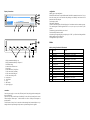
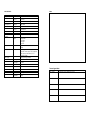
Version: 2008-04-02
Multi-IQ
Firmware:
(Serial Number / Seriennummer)
RS232-Data Manager for UPS
4 x RS232 / 1 x LAN-Contacts
flash upgradeable
User manual
Manual English
MANUAL ENGLISH .......................................................................................... 2
GENERAL PROPERTIES: .........................................................................................
2
Description: .................................................................................................... 2
Display / Connections: .................................................................................... 3
connection: ..................................................................................................... 3
configuration: ................................................................................................. 3
TABLES: .............................................................................................................. 3
table 1: pinning / functions of LAN-contacts: .................................................. 3
table 2 : DIP-switch functions ......................................................................... 4
system start: .................................................................................................... 4
Firmware upgrades ......................................................................................... 4
troubleshooting: .............................................................................................. 4
technical details: ............................................................................................. 5
Notes: ............................................................................................................. 5
Firmware Upgrade Notes: ............................................................................... 5
general properties:
Description:
Multi-IQ is a data manager for controlling and monitoring one ups by multiple computers with RS232communications, comparable to a multiplexer but with enhanced communications and security functions.
Multi-IQ is connected to the serial port of the ups and reads out all ups parameters about one time a second.
Data is requested and transmitted with the ups specific protocol, using the same security options as the ups
(i.e. checksums, error messages).
Data is cached in an internal RAM to be able to serve several requests for data simultaneously.
The status information for the LAN-contacts are generated from the cached ups-data.
The LAN-contacts on output 5 can be used to integrate older components or software that does not support
RS232-communications. The optocoupler input for ups-shutdown is integrated in the ups-shutdown process
of Multi-IQ
The serial outputs 1-4 emulate the communication with a single ups, using the data transmitted from the ups
to the Multi-IQ and the protocol supported by the ups.
UPS commands are transmitted to the ups, executed by the Multi-IQ or, in case of critical commands such
as „ups off“, transmitted to the ups depending on all active systems’ commands.
Critical commands have to be given by all active systems and the LAN-contact (if enabled), in order to be
transmitted to the ups.
A system is considered „active“ as soon as it has sent one byte with the correct baud rate.
Is there no communication an a port for more then 2 minutes, the system is considered „inactive“ and is not
longer integrated in the ups shutdown process.
Additional Multi-IQs can be connected to each serial output to supply more then 4 computer systems with
RS232 communications. This way up to 2 generations of Multi-IQs (or up to 64 computers) can be served.
Display / Connections:
configuration:
Multi-IQ input- / output configuration
With the DIP switches on the rear panel different modes for the RS232 communication can be set. You can
choose the connect speed, a turbo mode when daisy chaining several Multi-IQ’s and activate the UPS
shutdown for the LAN contact port.
For the settings see table 1
LAN-contacts configuration:
The DB-15 connector (output5) of the Multi-IQ supplies 7 semiconductor switches to monitor ups status.
The 4 standard signals for AS400 applications can be set to „active open“ or „active closed“ by DIPswitches.
The remaining 3 signals are defined as „active closed“.
For functions and pin numbers see table 1.
A shutdown signal is supported by the optocoupler input (3-12 VDC = ups off) and can be integrated in the
Multi-IQ shutdown routine by DIP-switch.
For configuration of output 5 see table 2.
tables:
table 1: pinning / functions of LAN-contacts:
1 - display communication Multi-IQ / ups
2 - display communication Multi-IQ / computer 1-4
3 - load default settings
4 - communication- / hardware-error
5 - power supply
6 - LAN-contact closed „Utility Failure“
7 - LAN- contact closed„Low Battery“
8 - LAN- contact closed„On Bypass“
9 - LAN- contact closed„ups O.K.“
10 - to computer 1-4
11 - LAN-contacts
12 - to ups
13 - DIP-switches
14 - power supply input
connection:
Connect the power supply to a secure socket (UPS) and put the 3,5mm jack plug into the mounting on the
back side of Multi-IQ.
Connect the ups serial port and the input of the Multi-IQ. Use the cable that is normally used to connect
UPS and computer. Connect output 1 - 4 with the included 1:1-cable to a COM-port of the computers or
network interfaces.
The LAN-contacts of output 5 can be connected to either monitoring boards, contact multiplexers or pc’s
running a software for ups monitoring with dry contacts. A ups shutdown signal can be supported.
Pin #:
function:
options:
1
utility fail 1
standard function = „active closed“
2
low battery 1
standard function = „active closed“
3
on bypass 1
standard function = „active closed“
4
ups O.K. 1
standard function = „active closed“
5
signal ground 1
for above signals
7
ups-shutdown + , 3-12 VDC
enable ups shutdown by DIP-switch 2
8
ups-shutdown ground
9
utility fail 2
not configurable, „active open“
10
low battery 2
not configurable, „active open“
11
ups O.K. 2
not configurable, „active closed“
12
signal ground 2
for non-configurable signals
table 2 : DIP-switch functions
troubleshooting:
If there are errors while starting or running Multi-IQ, check these points:
DIP
function:
settings::
1
programm (for service only)
OFF = normal operation *
(don’t change)
2
ups shutdown at output 5
ON = not active *
OFF = active
3
sets the PC ports to the highest / lowest connect speed
supported by the ups software
ON = hihgest connect speed
OFF = lowest connect speed *
4
38.400 Baud connection between 2 Multi-IQ
ON = turbo mode for UPS port,
OFF = standard speed *
5
38.400 Baud connection between 2 Multi-IQ
ON = turbo mode for PC port 1
OFF = standard speed *
6
38.400 Baud connection between 2 Multi-IQ
ON = turbo mode for PC port 2
OFF = standard speed *
7
38.400 Baud connection between 2 Multi-IQ
ON = turbo mode for PC port 3
OFF = standard speed *
8
38.400 Baud connection between 2 Multi-IQ
ON = turbo mode for PC port 4
OFF = standard speed *
symptom:
possible cause:
what to do:
„ERROR“ blinks, no
communication between
Multi-IQ and ups
serial port of ups is not configured
correctly.
configure ups port
cable not connected correctly.
connect correctly
cable damaged
replace
ups serial port does not communicate
(check directly, without Multi-IQ)
contact manufacturer
cable between computer and MultiIQ damaged or not connected
correctly.
Connect correctly or replace
Interfaces of computer and Multi-IQ
work with different baud rates
set equal values for both
interfaces
Multi-IQ not connected to power
supply
connect
Multi-IQ has no connection to ups
(„ERROR“ blinks).
Check this point
ups shutdown for one or more
computers not activated (software
settings).
Activate this function.
Shutdown time preset too long.
Set shorter (or shortest
possible) time.
Shutdown signal for output 5 enabled
though no hardware is installed or
doesn’t support ups shutdown
disable shutdown at output 5
Software reports „no
communication with
ups“
* = default settings
system start:
Connect the Multi-IQ with the power supply. Now the Multi-IQ contacts the ups and starts collecting data.
The transmission is monitored with LED’s in the front. The status LED’s monitor the actual condition of the
LAN contacts at output 5.
Start the computers / network interfaces and ups software and choose the right ups model. Configure the
COM-port for the baud rate you have chosen for the output of the Multi-IQ. Note: Multi-IQ doesn’t support
hardware handshake in the current version.
Save the configuration and start the ups software. The software now starts communicating with the MultiIQ.
The data transmission is monitored with LED’s in the front for each output.
Firmware upgrades
The firmware of the Multi-IQ can be upgraded directly via a serial connection on port 1. This may be
necessary if there are changes in the existing communication protocols or when new ups protocols are
introduced.
The upgrade tool is a small EXE file which runs under Windows or DOS. It is supplied by your dealer or
can be downloaded from your dealer’s Internet site.
To upgrade Multi-IQ, connect port 1 of the multiplexer to COM2 on any DOS or Windows pc with a 1-1
connected 9-pin cable. Run the EXE file which supports the new firmware version and follow the on screen
instructions.
ups shutdown is not
executed after computers
have shut down
technical details:
ups input:
serial output 1-4:
LAN-Contacts
(output 5):
Notes:
connector:
DB9, male
protocol:
auto detect
connector:
DB9, female
settings:
1.200 Baud to 38.800 baud
protocol:
Xon/Xoff, 8N1
connector:
DB15, female
signals:
- utility failure
- low battery
- on bypass
- ups O.K.
high-level, 3-12 VDC (enable / disable via DIPswitch)
Contacts may be used with up to 48V DC, max
0.25A DC. The max. power is 3W. Example: At
48V is the max. current 62mA (I = P/U ->
3VA/48V=62,5mA)
plug-in power supply included
ups shutdown:
power supply:
mechanical data:
AC-voltage
110 - 240 VAC / 47 - 63 Hz
DC-voltage:
7,5 VDC
DC-current:
2A
size (HxWxD)
61x290x203 mm
weight:
ca. 1 kg
temperature:
0-40°C
Firmware Upgrade Notes:
Date / Datum
Upgraded to version / aktualisiert auf Version: