1
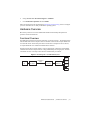
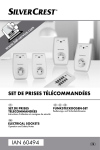
INSTALLATION GUIDE HDD-8265 This guide describes the HDD-8265, lists what you need to get started, and explains how to set up and get started with your hardware. Contents Safety Information .................................................................................................................... 2 Rack Mount Safety Information ....................................................................................... 3 Sicherheitshinweise .................................................................................................................. 4 Sicherheitshinweise zum Einbau in Gestellrahmen.......................................................... 6 Introduction .............................................................................................................................. 7 About the HDD-8265 Series............................................................................................. 7 Description and Features .......................................................................................... 7 HDD-8265 x4 System .............................................................................................. 7 What You Need to Get Started ......................................................................................... 7 Unpacking......................................................................................................................... 7 Hardware Installation and Use ................................................................................................. 8 Hardware Installation for x4 PXI Express Solution ......................................................... 8 Installing an NI 8262 ................................................................................................ 8 Cabling...................................................................................................................... 9 Powering Up the HDD-8265 for PXI Express System............................................. 9 Powering Down the HDD-8265 for PXI Express System........................................ 9 Driver Installation............................................................................................................. 9 Partitioning and Formatting.............................................................................................. 10 Windows XP Hosts................................................................................................... 10 Instructions for Windows 7 Hosts ............................................................................ 10 Virtual Disk Configuration............................................................................................... 11 Reconfiguring the HDD-8265 Virtual Disk for PXI Express Systems .................... 11 Factory Default Configuration.................................................................................. 12 Hardware Overview.................................................................................................................. 13 Functional Overview ........................................................................................................ 13 LED Indicators ................................................................................................................. 14 RAID Card Manufacturer ................................................................................................. 14 Cable Options ................................................................................................................... 14 Accessories ....................................................................................................................... 15 Specifications............................................................................................................................ 15 Physical............................................................................................................................. 15 Environment ..................................................................................................................... 15 Operating Environment ............................................................................................ 15 Storage Environment ................................................................................................ 15 Acoustic Emissions................................................................................................... 16 Cleaning............................................................................................................................ 16 Safety ................................................................................................................................16 Electromagnetic Compatibility ......................................................................................... 16 CE Compliance ................................................................................................................. 16 Online Product Certification ............................................................................................. 17 Environmental Management............................................................................................. 17 Electromagnetic Compatibility Information ............................................................................. 17 Worldwide Support and Services ............................................................................................. 18 Important Information............................................................................................................... 19 Warranty ........................................................................................................................... 19 Copyright .......................................................................................................................... 20 End-User License Agreements and Third-Party Legal Notices........................................ 20 Trademarks ....................................................................................................................... 20 Patents ............................................................................................................................... 21 Export Compliance Information ....................................................................................... 21 WARNING REGARDING USE OF NATIONAL INSTRUMENTS PRODUCTS ....... 21 Safety Information The following section contains important safety information that you must follow when installing and using the module. Do not operate the module in a manner not specified in this document. Misuse of the module can result in a hazard. You can compromise the safety protection built into the module if the module is damaged in any way. If the module is damaged, return it to National Instruments for repair. Do not substitute parts or modify the module except as described in this document. Use the module only with the chassis, modules, accessories, and cables specified in the installation instructions. You must have all covers and filler panels installed during operation of the module. Do not operate the module in an explosive atmosphere or where there may be flammable gases or fumes. If you must operate the module in such an environment, it must be in a suitably rated enclosure. Clean the module with a soft, nonmetallic brush. Make sure that the module is completely dry and free from contaminants before returning it to service. To avoid risk of explosion, use only the correct type of replacement batteries. Dispose of used batteries according to the instructions. Operate the module only at or below Pollution Degree 2. Pollution is foreign matter in a solid, liquid, or gaseous state that can reduce dielectric strength or surface resistivity. The following is a description of pollution degrees: • Pollution Degree 1 means no pollution or only dry, nonconductive pollution occurs. The pollution has no influence. • Pollution Degree 2 means that only nonconductive pollution occurs in most cases. Occasionally, however, a temporary conductivity caused by condensation must be expected. • Pollution Degree 3 means that conductive pollution occurs, or dry, nonconductive pollution occurs that becomes conductive due to condensation. 2 | ni.com | HDD-8265 Installation Guide You must insulate signal connections for the maximum voltage for which the module is rated. Do not exceed the maximum ratings for the module. Do not install wiring while the module is live with electrical signals. Do not remove or add connector blocks when power is connected to the system. Avoid contact between your body and the connector block signal when hot swapping modules. Remove power from signal lines before connecting them to or disconnecting them from the module. Operate the module at or below the measurement category1 marked on the hardware label. Measurement circuits are subjected to working voltages2 and transient stresses (overvoltage) from the circuit to which they are connected during measurement or test. Measurement categories establish standard impulse withstand voltage levels that commonly occur in electrical distribution systems. The following is a description of measurement categories: • Measurement Category I is for measurements performed on circuits not directly connected to the electrical distribution system referred to as MAINS3 voltage. This category is for measurements of voltages from specially protected secondary circuits. Such voltage measurements include signal levels, special equipment, limited-energy parts of equipment, circuits powered by regulated low-voltage sources, and electronics. • Measurement Category II is for measurements performed on circuits directly connected to the electrical distribution system (MAINS3). This category refers to local-level electrical distribution, such as that provided by a standard wall outlet (for example, 115 AC voltage for U.S. or 230 AC voltage for Europe). Examples of Measurement Category II are measurements performed on household appliances, portable tools, and similar modules. • Measurement Category III is for measurements performed in the building installation at the distribution level. This category refers to measurements on hard-wired equipment such as equipment in fixed installations, distribution boards, and circuit breakers. Other examples are wiring, including cables, bus bars, junction boxes, switches, socket outlets in the fixed installation, and stationary motors with permanent connections to fixed installations. • Measurement Category IV is for measurements performed at the primary electrical supply installation (<1,000 V). Examples include electricity meters and measurements on primary overcurrent protection devices and on ripple control units. Rack Mount Safety Information Due to the device weight, two people should work together to mount the device in a rack. Caution Caution Install the unit as low as possible in the rack to maintain a lower center of gravity and prevent the rack from tipping when moved. 1 2 3 Measurement categories, also referred to as installation categories, are defined in electrical safety standard IEC 61010-1. Working voltage is the highest rms value of an AC or DC voltage that can occur across any particular insulation. MAINS is defined as a hazardous live electrical supply system that powers equipment. Suitably rated measuring circuits may be connected to the MAINS for measuring purposes. HDD-8265 Installation Guide | © National Instruments | 3 Follow these safety guidelines when installing the device in a rack: • Elevated Operating Ambient—If installed in a closed or multi-unit rack assembly, the operating ambient temperature of the rack environment may be greater than room ambient temperature. Therefore, you should install the equipment in an environment compatible with the maximum ambient temperature (Tma) of 40 °C. • Reduced Air Flow—When installing the equipment in a rack or cabinet, do not compromise the amount of airflow required for safe operation of the equipment. • Mechanical Loading—When mounting the equipment in the rack or cabinet, avoid uneven mechanical loading that could create a hazardous condition. • Circuit Overloading—When connecting the equipment to the supply circuit, avoid overloading the circuits. Refer to equipment nameplate ratings to avoid damaging over current protection and supply wiring. • Reliable Earthing—Maintain reliable earthing of rack-mounted equipment, especially when using supply connections other than direct connections to the branch circuit (for example, power strips). • Redundant Power Supplies—Where redundant power supplies are provided with the equipment, connect each power supply to a separate circuit to optimize the equipment redundancy. • Servicing—Prior to servicing the equipment, disconnect all power supplies. Sicherheitshinweise Im folgenden Abschnitt finden Sie wichtige Sicherheitshinweise, die beim Einbau und bei der Verwendung des Geräts unbedingt zu befolgen sind. Es sind keine Abweichungen von den nachfolgenden Richtlinien zulässig. Beim falschen Umgang mit dem Gerät kann es zu Schäden kommen. Bei einem defekten Gerät sind die eingebauten Schutzvorrichtungen unter Umständen nicht mehr wirksam. Alle defekten Geräte sollten daher an National Instruments zurückgesendet und umgetauscht werden. Soweit nicht anders beschrieben, dürfen keine Veränderungen am Gerät vorgenommen werden. Das Gerät darf nur zusammen mit den in der Installationsanleitung aufgeführten Chassis, Modulen, Kabeln und Zubehör-teilen genutzt werden. Beim Betrieb des Geräts müssen alle Blenden und Abdeckungen angebracht sein. Das Gerät darf nicht an Orten genutzt werden, an denen Explosionsgefahr besteht oder an denen entzündliche Gase oder Dämpfe auftreten können. Kann auf den Einsatz an einem solchen Ort nicht verzichtet werden, muss das Gerät mit einem vorschriftsmäßigen Schutzgehäuse versehen werden. Das Gerät sollte mit einer weichen, nicht metallischen Bürste gereinigt werden. Bevor das Gerät nach der Reinigung wieder eingesetzt wird, muss es vollständig trocken und frei von Verschmutzungen sein. 4 | ni.com | HDD-8265 Installation Guide Wenn die Batterien ersetzt werden müssen, sind stets die vorgeschriebenen Batterietypen zu verwenden. Falsche Batterietypen erhöhen die Explo-sionsgefahr. Die alten Batterien sind wie beschrieben zu entsorgen. Das Gerät sollte in einer Umgebung verwendet werden, die maximal den Verschmutzungsgrad 2 aufweist. Als Verschmutzung gelten alle flüssigen, festen und gasförmigen Fremdstoffe, die die Leitfähigkeit der ansonsten nicht leitenden Oberfläche erhöhen können. Nachfolgend sind alle Verschmutzungsgrade im Einzelnen beschrieben: • Verschmutzungsgrad 1 bedeutet keine Verschmutzung oder geringe Verschmutzung durch trockene, nicht leitende Partikel. Diese Kategorie hat keinen Einfluss auf das Gerät. • Verschmutzungsgrad 2 bedeutet, dass die meisten Schmutzpartikel nicht leitend sind. Bisweilen muss jedoch mit Kriechströmen durch Kondenswasser gerechnet werden. • Verschmutzungsgrad 3 bedeutet, dass die Schmutzpartikel selbst oder in Verbindung mit Kondenswasser Kriechströme verursachen können. Alle angeschlossenen Leitungen, an denen die maximale Eingangsspannung für das Gerät zu erwarten ist, müssen isoliert sein. Die maximal zulässigen Eingangswerte des Geräts dürfen auf keinen Fall überschritten werden. Stellen Sie keine Verbindungen her, während das Gerät in Betrieb ist. Solange das Gerät an ein Netzteil angeschlossen ist, dürfen keine Anschlussblöcke eingesteckt oder herausgezogen werden. Wenn Sie Geräte ohne Ausschalten des Chassis auswechseln müssen, achten Sie darauf, dass Sie nicht mit dem Anschlussblock in Berührung kommen. Trennen Sie alle Leitungen zunächst von der Signalquelle, bevor Sie sie vom Gerät trennen oder an das Gerät anschließen. Das Gerät darf maximal in der Messkategorie1 betrieben werden, die auf dem Etikett verzeichnet ist. Jeder Messkreis hat eine bestimmte Arbeitsspannung2. Daneben können jedoch durch den Stromkreis, an den das Messgerät angeschlossen ist, vorübergehende Spitzen (Überspannungen) auftreten. Messkategorien stellen einen Standard für die Belastbarkeit auf Spannungsspitzen dar. Nachfolgend sind alle Messkategorien im Einzelnen beschrieben: • Messkategorie I gilt für Messungen an Schaltungen, die nicht direkt mit dem Stromnetz3 verbunden sind, also keine Netzspannung führen. In diese Kategorie fallen alle Spannungsmessungen in Nebenstromkreisen mit speziellen Schutzschaltungen. Dazu zählen Pegel-messungen sowie Messungen an speziellen Geräten, Bauteilen mit begrenzter Spannung, Schaltkreisen mit Niederspannungsquellen und elektronischen Schaltungen. • Messkategorie II gilt für Messungen an Schaltungen, die direkt mit dem Stromnetz3 verbunden sind. In diese Kategorie fallen alle ortsveränderlichen Elektroanschlüsse, z. B. Haushaltssteckdosen (230 V~). Zur Messkategorie II zählen beispielsweise Messungen an Haushaltsgeräten oder tragbaren Werkzeugen. 1 2 3 Messkategorien (auch als Installationskategorien bezeichnet) sind im IEC-Standard 61010-1 bzw. der deutschen Entsprechung DIN EN 61010-1, “Sicherheitsbestimmungen für elektrische Mess-, Steuer-, Regel- und Laborgeräte”, definiert. Die Arbeitsspannung ist die höchste zulässige Effektivspannung, für die die Isolierung ausgelegt sein muss. Das Stromversorgungsnetz ist definiert als Energieversorgungssystem für technische Geräte, das unter einer für den Menschen gefährlichen Spannung steht. An das Stromversorgungsnetz dürfen nur entsprechend ausgelegte Messgeräte und -leitungen angeschlossen werden. HDD-8265 Installation Guide | © National Instruments | 5 • Messkategorie III gilt für Messungen an Elektroinstallationen von Gebäuden. In diese Kategorie fallen alle Messungen an ortsfesten Elektroanlagen wie Verteilern oder Schutzschaltern. Zu dieser Kategorie zählen ebenfalls Elektrokabel, Stromschienen, Abzweigdosen, Schalter, Steckdosen ortsfester Elektroinstallationen sowie Elektromotoren, die fest an Elektroinstallationen angeschlossen sind. • Messkategorie IV gilt für Messungen an Starkstromanlagen mit Nennspannungen bis 1000 V. In diese Kategorie fallen Stromzähler, Messungen an Starkstromsicherungen und Rundsteueranlagen. Sicherheitshinweise zum Einbau in Gestellrahmen Wegen seines Gewichts sollte das Gerät immer zu zweit in einen Gestellrahmen eingebaut werden. Vorsicht! Bestücken Sie jeden Gestellrahmen von unten nach oben, so dass der Schwerpunkt des Rahmens möglichst tief liegt und er beim Anstoßen nicht umkippt. Vorsicht! Beim Einbau in einen Gestellrahmen sind folgende Sicherheitsrichtlinien zu befolgen: • Betriebstemperatur—In einem geschlossenen Gestell oder einem Gestell für mehrere Geräte kann die Betriebstemperatur höher als die Umgebungstemperatur sein. Bauen Sie das Gerät daher nur dort ein, wo die maximale Umgebungstemperatur (tma) 40 °C nicht übersteigt. • Belüftung—Sorgen Sie beim Einbau in ein Gestell oder Gehäuse für genügend Belüftung, um den sicheren Betrieb des Geräts zu gewährleisten. • Lastverteilung—Sorgen Sie beim Einbau in ein Gehäuse oder Gestell für gleichmäßige Lastverteilung. • Überlast—Achten Sie beim Anschließen des Geräts an die Stromversorgung darauf, dass die maximal zulässigen Werte für Strom und Spannung nicht überschritten werden. Die technischen Daten finden Sie auf dem Etikett des Geräts. Bei Überlastung können die Überstromschaltung und die Kabel beschädigt werden. • Erdung—Achten Sie darauf, dass alle in Gestelle eingebauten Geräte ordnungsgemäß geerdet sind. Das gilt insbesondere, wenn die Geräte nicht direkt an die Stromversorgung angeschlossen sind, sondern beispielsweise über Mehrfachsteckdosen). • Redundante Stromversorgung—Wenn es für das Gerät mehrere Netzteile gibt, schließen Sie jedes Netzteil zur Steigerung der Ausfallsicherheit an einen separaten Stromkreis an. • Instandhaltung—Alle Geräte sind vor der Instandhaltung von der Stromversorgung zu trennen. 6 | ni.com | HDD-8265 Installation Guide Introduction The HDD-8265 series are applications of cabled PCI Express technology. These products leverage commercially available enterprise class RAID controllers and hard drives. About the HDD-8265 Series Description and Features The HDD-8265 is a 2U chassis specifically designed for streaming to and from disk applications by National Instruments. This chassis supports up to 12 enterprise class SATA hard drives controlled by a 12-port PCI Express RAID controller. This system is preconfigured as RAID 0; however, the system also is validated to perform well under RAID5. The RAID card also supports additional modes such as RAID 1, RAID 6, RAID 10, RAID 50, and JBOD, but NI has not specifically validated these RAID modes for performance. Refer to the included RAID controller user manual or guide for more information about these modes. HDD-8265 x4 System The RAID system consists of an NI 8262 in a PXI Express or CompactPCI Express chassis, connected to the HDD-8265. This system can use the full bandwidth of PCI Express x4 (Generation 1) technology and can write sequentially at approximately 700 Mbytes/s across the entire array. Using RAID5, the HDD-8265 can sustain write speeds of approximately 600 Mbytes/s over the entire array. Sequential reads are sustainable at over 700 Mbytes/s for RAID0 and RAID5. What You Need to Get Started To set up and use your HDD-8265 for PXI Express, you need the following hardware and software to use with your PXI Express chassis and controller: • Host: PXI Express controller and chassis • RAID array: HDD-8265 • Host connection: NI 8262 • Cable: PCI Express x4 • Software: RAID drivers (on the included CD) Note Certain PXI Express controllers and chassis are preferred for optimal performance. Refer to Knowledgebase 57ECR5HB at ni.com/support for more information about controller and chassis use with the HDD-8265. Unpacking Your HDD-8265 system is preassembled and preconfigured for use. You need only to remove the HDD-8265 RAID storage chassis from the shipping box and assemble your system. There is no need to open your HDD-8265 chassis. The system is preconfigured and sealed. HDD-8265 Installation Guide | © National Instruments | 7 Your HDD-8265 system is sensitive to electrostatic damage (ESD). ESD can damage several components on the system. Caution Caution Never touch the exposed pins of connectors. Doing so may damage the device. To avoid such damage in handling the device, take the following precautions: • Ground yourself using a grounding strap or by holding a grounded object. • Touch any antistatic packaging to a metal part of the chassis before removing the device from the package. Hardware Installation and Use This section explains how to install and use the HDD-8265 for PXI Express. Hardware Installation for x4 PXI Express Solution The following are general instructions for installing the HDD-8265 for PXI Express system. Consult your computer user manual or technical reference manual for specific instructions and warnings. Installing an NI 8262 Complete the following steps to install the NI 8262 in your PXI Express or CompactPCI Express chassis: 1. Power off your PXI Express or CompactPCI Express chassis, but leave it plugged in while installing the NI 8262. The power cord grounds the chassis and protects it from electrical damage while you install the module. 2. Locate an available PXI Express or CompactPCI Express slot in the chassis (x4 or greater). The NI 8262 must not be installed in the controller slot (slot 1 in a PXI Express chassis). To protect both yourself and the chassis from electrical hazards, leave the chassis off until you finish installing the NI 8262. Caution 3. Remove or open any doors or covers blocking access to the slot where you intend to install the NI 8262. 4. Touch the metal part of the case to discharge any static electricity that might be on your clothes or body. 5. Make sure the injector/ejector handle is in its downward position. Be sure to remove all connector packaging and protective caps from retaining screws on the module. Align the NI 8262 with the card guides on the top and bottom of the system controller slot. Do not raise the injector/ejector handle as you insert the NI 8262. It will not insert properly unless the handle is in its downward position so that it does not interfere with the injector/ejector rail on the chassis. Caution 8 | ni.com | HDD-8265 Installation Guide 6. Hold the handle as you slowly slide the module into the chassis until the handle catches on the injector/ejector rail. 7. Raise the injector/ejector handle until the module firmly seats into the backplane receptacle connectors. The front panel of the NI 8262 should be even with the front panel of the chassis. 8. Tighten the bracket-retaining screws on the top and bottom of the front panel to secure the NI 8262 to the chassis. 9. Replace or close any doors or covers to the chassis. Cabling Connect the cabled PCI Express x4 cable to both NI 8262 and the HDD-8265 chassis. The cables have no polarity, so you can connect either end to either the card or chassis. Caution Do not remove the cable after the system is powered on. Doing so can hang or cause errors in applications communicating with devices. If a cable becomes unplugged, plug it back into the system. (You may need to restart your computer.) Note For more information about cables, refer to the RAID Card Manufacturer section. Powering Up the HDD-8265 for PXI Express System Follow these steps to power up the HDD-8265 for PXI Express system: 1. Turn on the HDD-8265 chassis. The power switch is on the power supply on the back of the chassis. The system should not power on when this switch is turned on. Turning this switch to the ON position enables the chassis to be powered on by the host controller when the host is powered on. 2. Power-on the host. The HDD-8265 chassis now should turn on. Powering Down the HDD-8265 for PXI Express System Because operating systems and drivers commonly make the assumption that PCI devices are present in the system from power-up to power-down, it is important not to power off the HDD-8265 chassis independently. Powering off the HDD-8265 chassis while the host still is on can cause data loss, crashes, or hangs. When you shut down the host controller, the HDD-8265 is sent a signal over the cabled PCI Express link to shut down also. Driver Installation For driver installation information, consult the driver installation chapter of the included RAID controller user manual or guide. The included CD includes both a scsiport and storport driver for the RAID card. Use the scsiport driver, although you can install the storport driver under Windows 7/Vista. The scsiport driver is more stable and yields higher performance in testing. If your CD does not include a Windows 7 driver, refer to the RAID card manufacturer Web site for updates. HDD-8265 Installation Guide | © National Instruments | 9 Partitioning and Formatting The Areca RAID card in the HDD-8265 has a feature called Variable Sector Size, used to create the RAID0 virtual disk. This allows the RAID card to present disks to Windows XP that are larger than 2 TB. Windows XP Hosts Complete the following steps when using a Windows XP host: 1. Open your disk management console by pressing <Windows-R>. 2. Enter diskmgmt.msc and press <Enter>. The Initialize Disk window should open automatically. If it does not, right-click the minus symbol within a red circle on the disk you are trying to initialize and select Initialize Disk. 3. Ensure that your virtual disk is selected for initialization and click OK. Your disk now shows up as unallocated in the Disk Management utility with a black bar across the top. 4. Right-click on the unallocated disk and select New Partition to launch the New Partition Wizard. 5. Select Next to move to Partition Type. Choose your partition type and click Next. 6. In Specify Partition Size, the maximum partition size is chosen by default. Click Next. 7. In Assign Drive Letter or Path, you may assign a drive letter to your partition. Choose a drive letter and click Next. 8. In Format Partition, change the Allocation Unit size to 64 KB, which improves performance in sequential read and write applications. 9. Select Perform a quick format and click Next. 10. Click Finish to exit the New Partition Wizard. Note In Windows XP, the maximum volume size is 16 TB. For any HDD-8265 variants larger than 16 TB, the default configuration consists of multiple volumes of 16 TB or less. Instructions for Windows 7 Hosts Complete the following steps when using a Windows 7 host: 1. Open your disk management console by pressing <Windows-R>. 2. Enter diskmgmt.msc and press <Enter>. The Initialize Disk window opens. 3. Choose GPT and click OK. Your disk now shows up as unallocated in the Disk Management utility with a black bar across the top. 4. Right-click on the unallocated disk. 5. Select New Simple Volume to launch the New Simple Volume Wizard. 6. In Specify Volume Size, the maximum volume size is chosen by default. Click Next. 7. In Assign Drive Letter or Path, you may assign a drive letter to your new volume. Choose a drive letter and click Next. 8. In Format Partition, change the Allocation Unit size to 64 KB, which improves performance in sequential read and write applications. 10 | ni.com | HDD-8265 Installation Guide 9. Ensure that Perform a quick format is selected and click Next. 10. Click Finish to exit the New Simple Volume Wizard. Note For any HDD-8265 variants larger than 16 TB, the default configuration consists of multiple volumes of 16 TB or less. If you require the entire array capacity in a single volume, enter the RAID utility to configure the RAID volume for maximum capacity. If you have multiple HDD-8265 chassis in your system, Windows 7 gives you the option to combine these disks into spanned (stacked), stripped (RAID0), or mirrored (RAID1) volumes. Using the stripped mode, you can combine the sum capacity of your HDD-8265 chassis to a single drive letter. You will incur a slight performance penalty for using this mode, but it may greatly simplify your programming. Note Powering off the HDD-8265 chassis while the host still is on can cause data loss, crashes, or hangs. When you shut down your host computer, your HDD-8265 turns off. Virtual Disk Configuration Reconfiguring the HDD-8265 Virtual Disk for PXI Express Systems The HDD-8265 systems are preconfigured in RAID0 for performance reasons. The systems are validated to function well using RAID0 and RAID5. The RAID card supports additional RAID modes; however, NI has not specifically validated the performance of these additional RAID modes. Refer to Appendix F of the included RAID controller user manual for definitions of various RAID modes. Reconfiguring your RAID arrays erases all data on your system. Back up all data before reconfiguring. Caution There are two methods of reconfiguring the RAID arrays: • Shortly after powering on your host system, follow the onscreen directions for entering the option ROM configuration menu. • Install the RAID management software from within Windows. The RAID management utility is on the included CD or from the RAID controller manufacturer’s Web site. Refer to Chapters 5 and 6 of the included RAID controller user manual for more information about installing and using the management software. To reconfigure your HDD-8265 from its default state of RAID0 to a fault-tolerant mode of RAID5, complete the following steps. These instructions use the ArcHTTPGUI browser-based RAID management console. Refer to Chapters 5 and 6 of the included RAID controller user manual for more information about installing and using this software. 1. Delete any previous RAID sets by clicking Delete RAID Set under RAID Set Functions. 2. Click Create RAID Set under RAID Set Functions. HDD-8265 Installation Guide | © National Instruments | 11 3. Select all 12 drives. Check Confirm the Operation and click Submit. 4. Click Create Volume Set under Volume Set Functions. 5. Click Submit to create a volume set on the RAID set you just created. 6. Change Volume RAID Level to RAID5. 7. Change Greater Two TB Volume Support to 4 K Block. 8. Change Volume Initialization Mode to Background Initialization. 9. Click Confirm the Operation and click Submit. For best performance in fault-tolerant RAID modes, set Volume Cache Mode to Write Back, which is its default value. While using Write Back mode, the RAID card holds data in local memory that has not been written to disk. This can cause a loss of data if you have a sudden power failure during a write operation. To ensure the integrity of your data through a power failure, you can purchase and install the battery backup accessory, which keeps the data fresh in memory for about 72 hours. Refer to Appendix B and the Data Protection section in Appendix F of the included RAID controller user manual for more information about the battery backup module. You can purchase the battery backup module (part number 781468-01) from National Instruments. Follow the instructions in this guide under the Partitioning and Formatting section to configure your new virtual disk for use with your Windows operating system. When reconfiguring the HDD-8265, you must choose 4 KB sector block size to see virtual disks larger than 2 TB in Windows. For Areca RAID controllers, you can find this setting under Greater Two TB Volume Support while creating a volume. Note Booting from the HDD-8265 has not been validated and is not supported. Factory Default Configuration If you need to reset your HDD-8265 to factory default settings, complete the following steps when creating your virtual disk. Unless otherwise noted below, leave other settings at their default values These instructions use the ArcHTTPGUI browser-based RAID management console. Refer to Chapters 5 and 6 of the included RAID controller user manual for more information about installing and using this software. Delete any previous RAID sets by clicking Delete RAID Set under RAID Set Functions. 1. Click Create RAID Set under RAID Set Functions. 2. Select all 12 drives. Click Confirm the Operation and click Submit. 3. Click Create Volume Set under Volume Set Functions. 4. Click Submit to create a volume set on the RAID set you just created. 5. Change Volume RAID Level to RAID0. 12 | ni.com | HDD-8265 Installation Guide 6. Change Greater Two TB Volume Support to 4 K Block. 7. Click Confirm the Operation and click Submit. Follow the instructions in this guide under the Partitioning and Formatting section to configure your new virtual disk for use with your Windows operating system. Hardware Overview This section presents an overview of HDD-8265 hardware functionality and explains the operation of each functional unit. Functional Overview The HDD-8265 is based on PCI Express technology, as shown in Figure 1. The NI 8262 paired with the HDD-8265 uses PCI Express redrivers to enable control of a PCI Express RAID card in an external chassis. The PCI Express redriver architecture is transparent to device drivers, so only the RAID driver is needed for the HDD-8265 to function. The link between the PC and the chassis is a x4 PCI Express link. This link is a dual-simplex communication channel comprised of low-voltage, differentially driven signal pairs. The link can transmit at a rate of 10 Gbps in each direction simultaneously in x4 mode. Figure 1. Block Diagram of an HDD-8265 System SATA Drive 1 Host PC PCI Express Re-Driver PCI Express Cable PCI Express Re-Driver PCI Express RAID Card SATA Drive 2 SATA Drive 3 SATA Drive n HDD-8265 Installation Guide | © National Instruments | 13 LED Indicators The LEDs on HDD-8265 cards give status information about power supplies and link state. The back of the HDD-8265 has two LEDs, one for power supply status and one for link state. Table 1 describes the meaning of the LEDs on the back of the HDD-8265. Table 1. NI HDD-8265 Back Panel Status LED Messages LED Color LINK Off Green PWR Meaning Link not established Link established Off Power off Green Power on Each hard drive on the front of the HDD-8265 has two LED indicators. Table 2 describes the meaning of the LEDs on the front of the hard drives. Table 2. NI HDD-8265 Hard Drive Status LED Messages LED Color Meaning PWR Off Drive not available or powered off Blue Drive powered on Off No read or write activity Blue Read or write in process Red Error or locate drive ACTIVITY RAID Card Manufacturer Manufacturer.....................................................Areca Model ................................................................ARC-1231ML Web site............................................................. www.areca.com.tw Cable Options The HDD-8265 systems support only the 3 m cable length. Table 3 shows the cable available from National Instruments. Table 3. National Instruments x4 Cable for Use with NI 8262 and HDD-8265 Cable Length (Meters) Description 3m Cabled PCI Express x4 copper cable (part number 779725-03) 14 | ni.com | HDD-8265 Installation Guide Accessories You can purchase a battery backup module for fault-tolerant RAID modes (part number 781468-01). Specifications This section lists the system specifications for the HDD-8265 series. These specifications are typical at 25 °C, unless otherwise stated. Physical Dimensions HDD-8265 ................................................ 2U × 440 × 558.8 mm (2U × 17.3 × 22.0 in.) Maximum cable length ..................................... 3 m Weight HDD-8265 6/12 TB ............................................. 19.87 kg (43.8 lb) typical 24 TB ................................................ 20.63 kg (45.48 lb) typical Power requirements Specification ............................................. 100 to 240 V, 7 to 3.5 A Measured, Peak Inrush ............................. 280 W Measured, Idle .......................................... 150 W Measured, Active...................................... 175 W Environment Maximum altitude............................................. 2,000 m (800 mbar) (at 25 °C ambient temperature) Pollution Degree ............................................... 2 Indoor use only. Operating Environment Ambient temperature range 6/12/24 TB................................................ 5 to 40 °C Relative humidity range.................................... 10 to 90%, noncondensing Storage Environment Ambient temperature range .............................. -20 to 70 °C Relative humidity range.................................... 5 to 95%, noncondensing HDD-8265 Installation Guide | © National Instruments | 15 Acoustic Emissions1 Sound pressure level Operator position ......................................53.7 dBA Sound power .....................................................60.8 dBA Cleaning Clean the HDD-8265 with a soft nonmetallic brush. Make sure the device is completely dry and free from contaminants before returning it to service. Safety This product is designed to meet the requirements of the following standards of safety for information technology equipment: • IEC 60950-1, EN 60950-1 • UL 60950-1, CSA 60950-1 For UL and other safety certifications, refer to the product label or the Online Product Certification section. Note Electromagnetic Compatibility This product meets the requirements of the following EMC standards for electrical equipment for measurement, control, and laboratory use: • EN 61326 (IEC 61326): Class A emissions; Basic immunity • EN 55011 (CISPR 11): Group 1, Class A emissions • AS/NZS CISPR 11: Group 1, Class A emissions • FCC 47 CFR Part 15B: Class A emissions • ICES-001: Class A emissions Note For the standards applied to assess the EMC of this product, refer to the Online Product Certification section. Note For EMC compliance, operate this device with shielded cabling. CE Compliance This product meets the essential requirements of applicable European Directives as follows: • 2006/95/EC; Low-Voltage Directive (safety) • 2004/108/EC; Electromagnetic Compatibility Directive (EMC) 1 Tested in accordance with ISO 7779; meets MIL-PRF-28800F requirements. These values reflect a system with 1 TB (6/12 TB actual size) drives. Systems with 2 TB drives (24 TB actual size) are marginally louder. 16 | ni.com | HDD-8265 Installation Guide Online Product Certification Refer to the product Declaration of Conformity (DoC) for additional regulatory compliance information. To obtain product certifications and the DoC for this product, visit ni.com/ certification, search by model number or product line, and click the appropriate link in the Certification column. Environmental Management NI is committed to designing and manufacturing products in an environmentally responsible manner. NI recognizes that eliminating certain hazardous substances from our products is beneficial to the environment and to NI customers. For additional environmental information, refer to the Minimize Our Environmental Impact web page at ni.com/environment. This page contains the environmental regulations and directives with which NI complies, as well as other environmental information not included in this document. Waste Electrical and Electronic Equipment (WEEE) At the end of the product life cycle, all products must be sent to a WEEE recycling center. For more information about WEEE recycling centers, National Instruments WEEE initiatives, and compliance with WEEE Directive 2002/96/EC on Waste and Electronic Equipment, visit ni.com/environment/ weee. EU Customers ⬉ᄤֵᙃѻક∵ᶧࠊㅵ⧚ࡲ⊩ ˄Ё RoHS˅ Ёᅶ᠋ National Instruments ヺড়Ё⬉ᄤֵᙃѻકЁ䰤ࠊՓ⫼ᶤѯ᳝ᆇ⠽䋼ᣛҸ (RoHS)DŽ݇Ѣ National Instruments Ё RoHS ড়㾘ᗻֵᙃˈ䇋ⱏᔩ ni.com/ environment/rohs_chinaDŽ (For information about China RoHS compliance, go to ni.com/environment/rohs_china.) Electromagnetic Compatibility Information This hardware has been tested and found to comply with the applicable regulatory requirements and limits for electromagnetic compatibility (EMC) as indicated in the hardware’s Declaration of Conformity (DoC)1. These requirements and limits are designed to provide reasonable protection against harmful interference when the hardware is operated in the intended electromagnetic environment. In special cases, for example when either highly sensitive or noisy hardware is being used in close proximity, additional mitigation measures may have to be employed to minimize the potential for electromagnetic interference. While this hardware is compliant with the applicable regulatory EMC requirements, there is no guarantee that interference will not occur in a particular installation. To minimize the potential for the hardware to cause interference to radio and television reception or to experience unacceptable performance degradation, install and use this hardware in strict accordance with the instructions in the hardware documentation and the DoC1. 1 The Declaration of Conformity (DoC) contains important EMC compliance information and instructions for the user or installer. To obtain the DoC for this product, visit ni.com/certification, search by model number or product line, and click the appropriate link in the Certification column. HDD-8265 Installation Guide | © National Instruments | 17 If this hardware does cause interference with licensed radio communications services or other nearby electronics, which can be determined by turning the hardware off and on, you are encouraged to try to correct the interference by one or more of the following measures: • Reorient the antenna of the receiver (the device suffering interference). • Relocate the transmitter (the device generating interference) with respect to the receiver. • Plug the transmitter into a different outlet so that the transmitter and the receiver are on different branch circuits. Some hardware may require the use of a metal, shielded enclosure (windowless version) to meet the EMC requirements for special EMC environments such as, for marine use or in heavy industrial areas. Refer to the hardware’s user documentation and the DoC1 for product installation requirements. When the hardware is connected to a test object or to test leads, the system may become more sensitive to disturbances or may cause interference in the local electromagnetic environment. Operation of this hardware in a residential area is likely to cause harmful interference. Users are required to correct the interference at their own expense or cease operation of the hardware. Changes or modifications not expressly approved by National Instruments could void the user’s right to operate the hardware under the local regulatory rules. Worldwide Support and Services The National Instruments website is your complete resource for technical support. At ni.com/ support you have access to everything from troubleshooting and application development self-help resources to email and phone assistance from NI Application Engineers. Visit ni.com/services for NI Factory Installation Services, repairs, extended warranty, and other services. Visit ni.com/register to register your National Instruments product. Product registration facilitates technical support and ensures that you receive important information updates from NI. A Declaration of Conformity (DoC) is our claim of compliance with the Council of the European Communities using the manufacturer’s declaration of conformity. This system affords the user protection for electromagnetic compatibility (EMC) and product safety. You can obtain the DoC for your product by visiting ni.com/certification. If your product supports calibration, you can obtain the calibration certificate for your product at ni.com/calibration. National Instruments corporate headquarters is located at 11500 North Mopac Expressway, Austin, Texas, 78759-3504. National Instruments also has offices located around the world. For telephone support in the United States, create your service request at ni.com/support or dial 512 795 8248. For telephone support outside the United States, visit the Worldwide Offices section of ni.com/niglobal to access the branch office websites, which provide up-to-date contact information, support phone numbers, email addresses, and current events. 18 | ni.com | HDD-8265 Installation Guide Important Information Warranty NI devices are warranted against defects in materials and workmanship for a period of one year from the invoice date, as evidenced by receipts or other documentation. National Instruments will, at its option, repair or replace equipment that proves to be defective during the warranty period. This warranty includes parts and labor. The media on which you receive National Instruments software are warranted not to fail to execute programming instructions, due to defects in materials and workmanship, for a period of 90 days from the invoice date, as evidenced by receipts or other documentation. National Instruments will, at its option, repair or replace software media that do not execute programming instructions if National Instruments receives notice of such defects during the warranty period. National Instruments does not warrant that the operation of the software shall be uninterrupted or error free. A Return Material Authorization (RMA) number must be obtained from the factory and clearly marked on the outside of the package before any equipment will be accepted for warranty work. National Instruments will pay the shipping costs of returning to the owner parts which are covered by warranty. National Instruments believes that the information in this document is accurate. The document has been carefully reviewed for technical accuracy. In the event that technical or typographical errors exist, National Instruments reserves the right to make changes to subsequent editions of this document without prior notice to holders of this edition. The reader should consult National Instruments if errors are suspected. In no event shall National Instruments be liable for any damages arising out of or related to this document or the information contained in it. EXCEPT AS SPECIFIED HEREIN, NATIONAL INSTRUMENTS MAKES NO WARRANTIES, EXPRESS OR IMPLIED, AND SPECIFICALLY DISCLAIMS ANY WARRANTY OF MERCHANTABILITY OR FITNESS FOR A PARTICULAR PURPOSE. CUSTOMER ’S RIGHT TO RECOVER DAMAGES CAUSED BY FAULT OR NEGLIGENCE ON THE PART OF NATIONAL INSTRUMENTS SHALL BE LIMITED TO THE AMOUNT THERETOFORE PAID BY THE CUSTOMER. NATIONAL INSTRUMENTS WILL NOT BE LIABLE FOR DAMAGES RESULTING FROM LOSS OF DATA, PROFITS, USE OF PRODUCTS, OR INCIDENTAL OR CONSEQUENTIAL DAMAGES, EVEN IF ADVISED OF THE POSSIBILITY THEREOF. This limitation of the liability of National Instruments will apply regardless of the form of action, whether in contract or tort, including negligence. Any action against National Instruments must be brought within one year after the cause of action accrues. National Instruments shall not be liable for any delay in performance due to causes beyond its reasonable control. The warranty provided herein does not cover damages, defects, malfunctions, or service failures caused by owner’s failure to follow the National Instruments installation, operation, or maintenance instructions; owner’s modification of the product; owner’s abuse, misuse, or negligent acts; and power failure or surges, fire, flood, accident, actions of third parties, or other events outside reasonable control. HDD-8265 Installation Guide | © National Instruments | 19 Copyright Under the copyright laws, this publication may not be reproduced or transmitted in any form, electronic or mechanical, including photocopying, recording, storing in an information retrieval system, or translating, in whole or in part, without the prior written consent of National Instruments Corporation. National Instruments respects the intellectual property of others, and we ask our users to do the same. NI software is protected by copyright and other intellectual property laws. Where NI software may be used to reproduce software or other materials belonging to others, you may use NI software only to reproduce materials that you may reproduce in accordance with the terms of any applicable license or other legal restriction. End-User License Agreements and Third-Party Legal Notices You can find end-user license agreements (EULAs) and third-party legal notices in the following locations: • Notices are located in the <National Instruments>\_Legal Information and <National Instruments> directories. • EULAs are located in the <National Instruments>\Shared\MDF\Legal\ license directory. • Review <National Instruments>\_Legal Information.txt for more information on including legal information in installers built with NI products. Trademarks Refer to the NI Trademarks and Logo Guidelines at ni.com/trademarks for more information on National Instruments trademarks. ARM, Keil, and µVision are trademarks or registered of ARM Ltd or its subsidiaries. LEGO, the LEGO logo, WEDO, and MINDSTORMS are trademarks of the LEGO Group. ©2013 The LEGO Group. TETRIX by Pitsco is a trademark of Pitsco, Inc.©2013 FIELDBUS FOUNDATION™ and FOUNDATION™ are trademarks of the Fieldbus Foundation. EtherCAT® is a registered trademark of and licensed by Beckhoff Automation GmbH. CANopen® is a registered Community Trademark of CAN in Automation e.V. DeviceNet™ and EtherNet/IP™ are trademarks of ODVA. Go!, SensorDAQ, and Vernier are registered trademarks of Vernier Software & Technology. Vernier Software & Technology and vernier.com are trademarks or trade dress. Xilinx is the registered trademark of Xilinx, Inc. 20 | ni.com | HDD-8265 Installation Guide Taptite and Trilobular are registered trademarks of Research Engineering & Manufacturing Inc. FireWire® is the registered trademark of Apple Inc. Linux® is the registered trademark of Linus Torvalds in the U.S. and other countries. Handle Graphics®, MATLAB®, Real-Time Workshop®, Simulink®, Stateflow®, and xPC TargetBox® are registered trademarks, and TargetBox™ and Target Language Compiler™ are trademarks of The MathWorks, Inc. Tektronix®, Tek, and Tektronix, Enabling Technology are registered trademarks of Tektronix, Inc. The Bluetooth® word mark is a registered trademark owned by the Bluetooth SIG, Inc. The ExpressCard™ word mark and logos are owned by PCMCIA and any use of such marks by National Instruments is under license. The mark LabWindows is used under a license from Microsoft Corporation. Windows is a registered trademark of Microsoft Corporation in the United States and other countries. Other product and company names mentioned herein are trademarks or trade names of their respective companies. Patents For patents covering National Instruments products/technology, refer to the appropriate location: Help»Patents in your software, the patents.txt file on your media, or the National Instruments Patent Notice at ni.com/patents. Export Compliance Information Refer to the Export Compliance Information at ni.com/legal/export-compliance for the National Instruments global trade compliance policy and how to obtain relevant HTS codes, ECCNs, and other import/export data. WARNING REGARDING USE OF NATIONAL INSTRUMENTS PRODUCTS (1) NATIONAL INSTRUMENTS PRODUCTS ARE NOT DESIGNED WITH COMPONENTS AND TESTING FOR A LEVEL OF RELIABILITY SUITABLE FOR USE IN OR IN CONNECTION WITH SURGICAL IMPLANTS OR AS CRITICAL COMPONENTS IN ANY LIFE SUPPORT SYSTEMS WHOSE FAILURE TO PERFORM CAN REASONABLY BE EXPECTED TO CAUSE SIGNIFICANT INJURY TO A HUMAN. (2) IN ANY APPLICATION, INCLUDING THE ABOVE, RELIABILITY OF OPERATION OF THE SOFTWARE PRODUCTS CAN BE IMPAIRED BY ADVERSE FACTORS, INCLUDING BUT NOT LIMITED TO FLUCTUATIONS IN ELECTRICAL POWER SUPPLY, COMPUTER HARDWARE MALFUNCTIONS, COMPUTER OPERATING SYSTEM SOFTWARE FITNESS, FITNESS OF COMPILERS AND DEVELOPMENT SOFTWARE USED TO DEVELOP AN APPLICATION, INSTALLATION ERRORS, HDD-8265 Installation Guide | © National Instruments | 21 SOFTWARE AND HARDWARE COMPATIBILITY PROBLEMS, MALFUNCTIONS OR FAILURES OF ELECTRONIC MONITORING OR CONTROL DEVICES, TRANSIENT FAILURES OF ELECTRONIC SYSTEMS (HARDWARE AND/OR SOFTWARE), UNANTICIPATED USES OR MISUSES, OR ERRORS ON THE PART OF THE USER OR APPLICATIONS DESIGNER (ADVERSE FACTORS SUCH AS THESE ARE HEREAFTER COLLECTIVELY TERMED “SYSTEM FAILURES”). ANY APPLICATION WHERE A SYSTEM FAILURE WOULD CREATE A RISK OF HARM TO PROPERTY OR PERSONS (INCLUDING THE RISK OF BODILY INJURY AND DEATH) SHOULD NOT BE RELIANT SOLELY UPON ONE FORM OF ELECTRONIC SYSTEM DUE TO THE RISK OF SYSTEM FAILURE. TO AVOID DAMAGE, INJURY, OR DEATH, THE USER OR APPLICATION DESIGNER MUST TAKE REASONABLY PRUDENT STEPS TO PROTECT AGAINST SYSTEM FAILURES, INCLUDING BUT NOT LIMITED TO BACK-UP OR SHUT DOWN MECHANISMS. BECAUSE EACH END-USER SYSTEM IS CUSTOMIZED AND DIFFERS FROM NATIONAL INSTRUMENTS' TESTING PLATFORMS AND BECAUSE A USER OR APPLICATION DESIGNER MAY USE NATIONAL INSTRUMENTS PRODUCTS IN COMBINATION WITH OTHER PRODUCTS IN A MANNER NOT EVALUATED OR CONTEMPLATED BY NATIONAL INSTRUMENTS, THE USER OR APPLICATION DESIGNER IS ULTIMATELY RESPONSIBLE FOR VERIFYING AND VALIDATING THE SUITABILITY OF NATIONAL INSTRUMENTS PRODUCTS WHENEVER NATIONAL INSTRUMENTS PRODUCTS ARE INCORPORATED IN A SYSTEM OR APPLICATION, INCLUDING, WITHOUT LIMITATION, THE APPROPRIATE DESIGN, PROCESS AND SAFETY LEVEL OF SUCH SYSTEM OR APPLICATION. 22 | ni.com | HDD-8265 Installation Guide Refer to the NI Trademarks and Logo Guidelines at ni.com/trademarks for more information on National Instruments trademarks. Other product and company names mentioned herein are trademarks or trade names of their respective companies. For patents covering National Instruments products/technology, refer to the appropriate location: Help»Patents in your software, the patents.txt file on your media, or the National Instruments Patents Notice at ni.com/patents. You can find information about end-user license agreements (EULAs) and third-party legal notices in the readme file for your NI product. Refer to the Export Compliance Information at ni.com/legal/export-compliance for the National Instruments global trade compliance policy and how to obtain relevant HTS codes, ECCNs, and other import/export data. © 2010–2013 National Instruments. All rights reserved. 373142D-01 Dec13