1
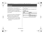
User Manual Airfonix R Series Wireless Receiver Models: AFX-19AR050 AFX-19PR001 Airfonix T Series Wireless Transmitter Models: AFX-19PT002 AFX-19PT102 EN Important Safety Instructions TO REDUCE THE RISK OF FIRE, ELECTRICAL SHOCK OR PRODUCT DAMAGE, DO NOT EXPOSE THE BOTTOM OF THE TRANSMITTER OR RECEIVER TO RAIN, MOISTURE, DRIPPING OR SPLASHING. PLEASE ENSURE THAT NO OBJECTS FILLED WITH LIQUIDS, SUCH AS VASES, ARE PLACED ON THE TRANSMITTER OR RECEIVER. FOR YOUR SAFETY, READ AND RETAIN ALL SAFETY AND OPERATING INSTRUCTIONS. FOLLOW ALL WARNINGS IN THIS MANUAL AND ON THE UNIT. POWER SOURCE To avoid any malfunctions of the unit, and to protect against electrical shock, fire or physical injury, please observe the following: • This system has been designed to work with 100-240 volt AC current. Connection to a line voltage other than that may create a safety and fire hazard and may damage the system. If you are unsure of the type of power supply to your home, consult your local dealer or power company. • Do not defeat the purpose of the polarized plug. A polarized plug has two blades, with one wider than the other. The wide blade is provided for your safety. If the provided plug does not fit into your outlet, consult an electrician for replacement of the obsolete outlet. • Do not run power cords under rugs or carpets or place heavy objects on them. • Damaged or deformed power cords are hazardous and should be replaced immediately by a qualified service technician. LOCATION • Air vents are provided in the cabinet to prevent the build up of excessive temperatures inside the unit. Do not place the unit in closed spaces, cover it with anything, or otherwise block the vents. • Keep the units away from heat sources such as fire pits, heating vents, central heating radiators and electric heaters. Never expose to continuous direct sunlight. • Keep the unit away from strong magnetic fields. CARE • The unit is splash proof only. Do not submerge in water. • Do not insert or drop anything into the unit through the air vents as this could cause serious damage, possibly resulting in fire. • Do not place any object containing water or other liquids on the unit. In the event that liquid should enter the cabinet, unplug the unit at once and contact the retailer or service center immediately. • Do not remove the cabinet. Touching parts inside the cabinet could result in electrical shock and damage to the unit. • Unplug the unit and the AC power adapter from the electrical outlet during lightning storms or when unused for long periods of time to prevent damage. • To avoid electrical shock and/or damage to the unit, do not handle the transmitter, receiver, external antenna, connecting cables or AC power adapter with wet hands. • The AC power adapter receives power as long as it is connected to the electrical outlet, even if the power switch on the unit is turned off. Always remove the AC power adapter from the electrical outlet before inspecting the adapter. • Use only the AC power adapter suppiled with the unit. This adapter is designed specifically for the unit. NON-USE PERIODS • ALWAYS turn the power OFF when not in use. When left unused for long periods of time, the unit should be unplugged from the AC outlet. VOLUME CONTROL • Do not turn up the volume while listening to a portion with very low level input or no audio signal. The speaker may be damaged when a peak level portion is played. CLEANING • Clean only with a dry or slightly damp cloth. Do not use any cleansing agents or solvents. Unplug the product from the wall outlet before cleaning. SERVICE • Do not open the cabinet of any components. There are no user-serviceable components in the product. Opening the cabinets may present a shock hazard, and any modification to the product will void your warranty. • Do not attempt to service the unit yourself. If water or any metal objects such as paper clips, wire or staples accidentally fall inside, disconnect the unit from the power source immediately and consult an authorized service center. SAVE THESE INSTRUCTIONS 2 www.airfonix.com EN Introduction Thank you for purchasing your Airfonix™ dual band Smart Channel™ wireless system. Airfonix professional wireless audio products offer the flexibility to arrange your wireless audio system to suit your current needs. You can easily expand your system by adding models to accommodate specific venues or location requirements. Use a combination of at least two of these products (one T Series wireless transmitter with one R Series wireless receiver) to create the perfect wireless solution. This manual covers the features, setup, and use for the following models: Airfonix R Series AFX-19AR050: Dual Band, two-channel wireless 50W mono/25+25W stereo receiver for passive speakers. AFX-19PR001: Dual Band, two-channel wireless receiver for active speakers. NOTE: Active speakers have built in amplifiers, while passive speakers do not have built in amplifiers. Airfonix T Series AFX-19PT002: Dual Band, two-channel wireless transmitter with dual balanced and SPDIF input jacks. AFX-19PT102: Dual Band, two-channel wireless transmitter with high-level and SPDIF input jacks. In addition to this manual, you will find a Quick Start Guide for each component you have purchased. Although these products are designed for easy operation, before you start we suggest you take the time to review these manuals to fully understand and take advantage of all the features in this system. About Airfonix Wireless Airfonix redefines wireless audio with the industry’s most advanced products for the professional and semi-pro audio markets. The products deliver uncompressed, 24-bit HDTV-compliant audio at 48 KHz sampling rate and are designed to retrofit any active or passive speaker, thereby bringing the freedom of wireless capability to any wired audio system. Airfonix products boast Smart Channel capability, a patent-pending technology developed by SST that automatically searches for and selects an uncongested channel from both the 2.4 GHz and 4.9-5.8 GHz ISM bands. Because of this unique dual-band operation and Smart Channel capability, Airfonix products are virtually impervious to interference from co-located wireless equipment. The result is clean, true HDTV audio delivered wirelessly with the industry’s most sophisticated transmission system developed especially for the stringent demands of professional users. Creating Your Airfonix Wireless System Every wireless system consists of at least two components–a transmitter and a receiver, both of which must be paired and tuned to the same channel. Select the T Series transmitter that suits your audio source input preferences, either model AFX-19PT002 or AFX-19PT102. You may connect two different audio sources to each of these models and switch between them by remote control or by using the button on the top of the unit. The Airfonix R Series receivers are designed to retrofit any active or passive speaker, bringing the freedom of wireless capability to any wired audio system. If your venue is large, with the speakers placed far apart, dock a receiver to each speaker. The R Series receivers can be mounted to your speakers with the included hardware or sit vertically using the stands. If your speakers are close together, select either R Series model AFX-19PR001 for active (powered) speakers or R Series model AFX-19AR050 for passive speakers. If your speakers are placed farther apart, use one R Series receiver for each speaker. All units will be secure when you properly pair your transmitter with your receivers. You may use two receivers with each transmitter and setup different channels for up to four wireless systems within a 150 foot range. The system will accommodate 4 to 8 ohms output. Any system with 70V will not work with these products. www.airfonix.com 3 EN Table of Contents Important Safety Instructions��������������������������������������������������������������� 2 About Airfonix Wireless����������������������������������������������������������������� 3 Creating Your Airfonix Wireless System����������������������������������������������������� 3 Introduction����������������������������������������������������������������������������� 3 Table of Contents������������������������������������������������������������������������ 4 Unpacking������������������������������������������������������������������������������ 5 Tools Necessary����������������������������������������������������������������������� 5 Overview AFX-19AR050 Receiver������������������������������������������������������������ 6 Overview AFX-19PR001 Receiver������������������������������������������������������������ 7 Overview AFX-19PT002 Transmitter���������������������������������������������������������� 8 Overview AFX-19PT102 Transmitter���������������������������������������������������������� 9 Planning Your Installation�������������������������������������������������������������� 10-12 Scenario 1: One Transmitter with One AFX-19AR050 Passive Receiver, One Zone Stereo������������� 10 Scenario 2: One Transmitter with Two AFX-19AR050 Passive Receivers, Two Zones Mono������������ 10 Scenario 3: One Transmitter with Two AFX-19AR050 Passive Receivers, Two Zones Stereo������������ 11 Scenario 4: One Transmitter with One AFX-19PR001 Active Receiver, One Zone Stereo�������������� 11 Scenario 5: One Transmitter with Two AFX-19PR001 Active Receivers, Two Zones Mono������������� 12 Scenario 6: One Transmitter with Two AFX-19PR001 Active Receivers, Two Zones Stereo������������� 12 Before You Begin��������������������������������������������������������������������� 13-14 Pairing Transmitters and Receivers: Setup Sequence����������������������������������������� 13 Setting Zone Codes for Your Installation��������������������������������������������������� 14 Placement and Mounting Options���������������������������������������������������������� 15 Mounting to Speakers or Walls���������������������������������������������������������� 15 Using the Stands���������������������������������������������������������������������� 15 Preparing Components for Use������������������������������������������������������������� 16 Install External Antenna���������������������������������������������������������������� 16 Preparing for Outdoor Use�������������������������������������������������������������� 16 Connecting the Receivers�������������������������������������������������������������� 17-20 Scenario 1: Connect One AFX-19AR050 Active Receiver to 4 ohm, 25W One Zone, Stereo������������ 17 Scenario 1: Connect One AFX-19AR050 Active Receiver to 8 ohm, 25W One Zone, Stereo������������ 17 Scenario 2: Connect Two AFX-19AR050 Active Receivers to 4 ohm, 50W One Zone, Mono������������ 17 Scenario 2: Connect Two AFX-19AR050 Active Receivers to 8 ohm, 36W One Zone, Mono������������ 18 Scenario 3: Connect Two AFX-19AR050 Active Receivers to 4 ohm, 25W Two Zones, Stereo����������� 18 Scenario 3: Connect Two AFX-19AR050 Active Receivers to 8 ohm, 36W Two Zones, Stereo����������� 18 Scenario 4: Connect One AFX-19PR001 Passive Receiver to Active Speakers, One Zone, Stereo������� 19 Using RCA Cables������������������������������������������������������������������ 19 Using XLR Cables������������������������������������������������������������������� 19 Scenario 5: Connect Two AFX-19PR001 Passive Receivers to Active Speakers, Two Zones, Mono������� 19 Using RCA Cables������������������������������������������������������������������ 19 Using XLR Cables������������������������������������������������������������������� 20 Scenario 6: Connect Two AFX-19PR001 Passive Receivers to Active Speakers, Two Zones, Stereo������ 20 Connecting the Transmitter������������������������������������������������������������ 20-21 Connecting Transmitter to One Source���������������������������������������������������� 21 Connecting Transmitter to Two Sources��������������������������������������������������� 21 Operation����������������������������������������������������������������������������� 22 Using the Remote��������������������������������������������������������������������� 22 Using the IR Extender������������������������������������������������������������������ 22 Troubleshooting Guide������������������������������������������������������������������� 23 Regulation Information ������������������������������������������������������������������� 25 R Series Specifications�������������������������������������������������������������������� 26 T Series Specifications�������������������������������������������������������������������� 27 4 www.airfonix.com EN Unpacking Please check to make sure the following accessories are included in each package for: T Series models AFX-19PT002 or AFX-19PT102 Wireless Transmitters External Antenna x1 Stand x2 IR Extender x1 1/4” Screw x 4 Remote Control x1 1” Screw x 4 Mounting Bracket x 2 Nylon Anchor x 4 9V Power Adapter x1 Optical Cable with SPDIF adaptor plug x1 User Manual x1 Quick Start Guide x1 R Series models AFX-19AR050 or AFX-19PR001 Wireless Receivers External Antenna x1 Stand x2 ! User Manual x1 1/4” Screw x 4 1” Screw x 4 Mounting Bracket x 2 Rain Cover x1 Nylon Anchor x 4 9V Power Adapter (AFX-19PR001) x 1 OR 24V Power Adapter (AFX-19AR050) x 1 Quick Start Guide x1 IMPORTANT: If you suspect transit damage or if anything is missing please contact Customer Service at (888) 778-2446 or www.airfonix.com immediately. Keep the shipping cartons and materials. Tools Necessary 1 Very Small Flat Screwdriver (similar to an eyeglass screwdriver) Phillips Screwdriver Pencil 2 Tape Measure www.airfonix.com 5 EN Overview AFX-19AR050 Receiver R Series model AFX-19AR050 Top Bottom Setting OFF PWR LINK 1 2 1 2 3 4 5 6 7 3 4 L R 5 ON 6 7 ANTENNA: Included external antenna attaches into this SMA jack. PWR LED: Lights green when linked and red in standby mode. Lights orange in pairing mode (see page 13). PWR BUTTON: Press to switch from standby to OFF. When in standby mode, the unit will power ON when linked to a transmitter. LINK LED: Lights green when units are linked. SPEAKER 4Ω L and R: Output connections 5-way binding posts use speaker cables to connect to passive speakers. NOTE: For use with 8 ohm speakers see Setting Zone Codes on page 14. Setting OFF/ON: Used to pair units and set zone codes. See pages 12 and 13 for more information. DC IN 24V: Used to connect supplied 24V AC adapter to an AC power source. NOTE: When connecting one receiver to one speaker the output will be 50W per channel. When connecting both speakers it will be 25W per channel. See Setting Zone Codes on page 14. 6 DC IN 24V www.airfonix.com EN Overview AFX-19PR001 Receiver R Series model AFX-19PR001 Top Bottom AUX BALANCE OUT L TRIGGER Setting OFF R PWR 1 2 1 2 3 4 5 6 7 8 L LINK 3 4 ON R 5 DC IN 9V 6 7 8 ANTENNA: Included external antenna attaches into this SMA jack. PWR LED: Lights green when linked on and red in standby mode. Lights orange in pairing mode (see page 13). LINK LED: Lights green when units are linked. TRIGGER JACK: Passes a low voltage (9V with 1K ohm series resistance) control signal to the trigger input jack of connected power amplifier. Connects using cable with a mini-phone plug. BALANCE OUT L and R: VAR level audio outputs for balanced left and right XLR-3M socket. AUX L and R: Analog output for left and right RCA jacks. Setting OFF/ON: Used to pair units and set zone codes. See pages 12 and 13 for more information. DC IN 9V: Used to connect supplied 9V AC adapter to an AC power source. ! IMPORTANT: To prevent signals mixing together, do not connect source to both the AUX L and R RCA jacks and the BALANCE IN sockets simultaneously. www.airfonix.com 7 EN Overview AFX-19PT002 Transmitter T Series model AFX-19PT002 Top Bottom 9 1 BALANCE IN IR PWR SOURCE MUTE VOLUME EXT IR AUX L SPDIF + 2 1 2 3 4 5 6 7 8 9 10 11 12 13 14 15 16 4 5 6 7 L LINK AUX 8 10 11 12 ON R 13 DC IN 9V 14 15 16 ANTENNA: Included external antenna attaches into this SMA jack. PWR LED: Lights green when powered on and red in standby mode. PWR BUTTON: Press to switch between standby mode and to power ON. VOLUME + and VOLUME – BUTTONS: Press to increase or decrease volume. MUTE LED: Lights red when mute mode is on. MUTE BUTTON: Press to mute or unmute audio. SPDIF and AUX LED: SPDIF LED lights green when audio source connected to SPDIF input source is powered on and selected. AUX LED lights green when audio source connected to the left and right RCA inputs marked AUX input OR the Balance In inputs and is powered on and selected. SOURCE BUTTON: Press to switch between SPDIF and AUX sources. IR SENSOR: Receives infrared signal from remote control. LINK LED: Lights green when units are linked. Blinks green while sending pairing signals (see page 13). EXT IR: Connects included IR extender. SPDIF: Use supplied optical cable or (coaxial cable not included) to connect this digital input jack with optical or digital output in your HDTV. BALANCE IN L and R: Connects to an audio source using XLR audio cables. AUX L and R: Connects to an analog audio source using RCA cables. Setting OFF/ON: Used to pair units and set zone codes. See pages 12 and 13 for more information. DC IN 9V: Used to connect supplied 9V AC adapter to an AC power source. ! 8 3 Setting OFF R SPDIF IMPORTANT: www.airfonix.com • To prevent signals mixing together, do not connect source to both the AUX L and R RCA jacks and the BALANCE IN sockets simultaneously. • When connecting an audio source using the SPDIF input, it must use either 44.1KHz or 48KHz sampling rates. Check the owner’s manual for your audio source if you are unsure. Overview AFX-19PT102 Transmitter EN T Series model AFX-19PT102 Top Bottom 9 1 HI-LEVEL IN INPUT IR PWR VOLUME MUTE L SOURCE SPDIF + 2 1 2 3 4 5 6 7 8 9 10 11 12 13 14 15 16 17 3 4 SPDIF Setting LINK EXT IR AUDIO TRIM AUX 5 6 7 R 8 10 11 12 R L 13 AUX 14 OFF DC IN 9V ON 15 16 17 ANTENNA: Included external antenna attaches into this SMA jack. PWR LED: Lights green when powered on and red in standby mode. PWR BUTTON: Press to switch between standby mode and to power ON. VOLUME + and VOLUME – BUTTONS: Press to increase or decrease volume. MUTE LED: Lights red when mute mode is on. MUTE Button: Press to mute or unmute audio. SPDIF and AUX LED: SPDIF LED lights green when audio source connected to SPDIF input source is powered on and selected. AUX LED lights green when audio source connected to the Hi-Level In inputs OR the left and right RCA inputs marked AUX input is powered on and selected. SOURCE BUTTON: Press to switch between SPDIF and AUX sources. IR SENSOR: Receives infrared signal from remote control. LINK LED: Lights green when units are linked. Blinks green while sending pairing signals (see page 13). EXT IR: Connects included IR extender. AUDIO TRIM: Dial turns to adjust input signal levels of audio sources connected to AUX and HI-LEVEL IN. NOTE: Make sure the audio trim is set to its lowest position before powering up. HI-LEVEL IN: Connects to an audio source using speaker cables. AUX L and R: Connects to an analog audio source using RCA cables. SPDIF: Use supplied optical cable or (coaxial cable not included) to connect this digital input jack with optical or digital output in your HDTV. Setting OFF/ON: Used to pair units and set zone codes. See pages 12 and 13 for more information. DC IN 9V: Used to connect supplied 9V AC adapter to an AC power source. ! IMPORTANT: • To prevent signals mixing together, do not connect source to both the AUX L and R RCA jacks and the HI-LEVEL IN sockets simultaneously. • When connecting an audio source using the SPDIF input, it must use either 44.1KHz or 48KHz sampling rates. Check the owner’s manual for your audio source if you are unsure. www.airfonix.com 9 EN Planning Your Installation The following examples will illustrate the versatility of the Airfonix wireless system. These illustrations are designed to demonstrate some of the many installations possible. Since all receivers are lightweight, compact and designed with a rugged, weatherized industrial chassis for outdoor use, you can easily move the components from indoor to outdoor sites and reconfigure them for different venues or situations. The R Series receivers include weather shields to further protect your components. All models can be easily mounted to speakers or walls with the included mounting hardware, rest on a flat surface such as a rack mount or stand vertically using the included stands. Each T Series transmitter has two channels, allowing you to connect two audio sources and switch back and forth with the included remote control. Most of the illustrations show this option, however in many situations you will only use one source. Possible Audio Sources include stereo receivers, DVD players, CD players, digital TVs, professional mixing consoles, gaming products, computers, iPods, MP3s or any product with a speaker output connection. Scenario 1: One Transmitter with One AFX-19AR050 Passive Receiver, One Zone Stereo T Series Remote Control Connected using digital (SPDIF) input HDTV Connected using analog (AUX) input R Series Audio Source 2 AFX-19AR050 Passive Speakers 4 ohm or 8 ohm 25W per channel Scenario 2: One Transmitter with Two AFX-19AR050 Passive Receivers, Two Zones Mono T Series Remote Control Connected using digital (SPDIF) input Connected using analog (AUX) input HDTV Audio Source 2 R Series AFX-19AR050 Passive Speaker 4 ohm or 8 ohm 25W per channel ! 10 www.airfonix.com R Series Outdoor open wireless range is up to 300 feet AFX-19AR050 Passive Speaker 4 ohm or 8 ohm 25W per channel IMPORTANT: The analog (AUX) inputs include Hi-Level In, Balance In and L and R RCA jack inputs. Connect your audio source to ONLY one of these inputs. EN Planning Your Installation Scenario 3: One Transmitter with Two AFX-19AR050 Passive Receivers, Two Zones Stereo T Series Remote Control Connected using digital (SPDIF) input Connected using analog (AUX) input HDTV Audio Source 2 Room 1 R Series AFX-19AR050 Indoor wireless range is between 100 to 150 feet. Room 2 NOTE: The range may vary significantly when using within walls constructed of solid brick, metal or concrete. AFX-19AR050 Passive Speakers 4 ohm or 8 ohm 25W per channel R Series Passive Speakers 4 ohm or 8 ohm 25W per channel NOTES: • The R Series receivers and T Series transmitters conveniently dock and undock to speakers or walls using the included mounting brackets. • You may pair a maximum of two receivers to each transmitter and use three sets of transmitters within a 150 foot range without conflict. • Rain shield covers are included with each receiver for protection in outdoor installations. Scenario 4: One Transmitter with One AFX-19PR001 Active Receiver, One Zone Stereo T Series Remote Control Connected using digital (SPDIF) input HDTV R Series AFX-19PR001 Active Speaker ! Connected using analog (AUX) input Audio Source 2 Active Speaker IMPORTANT: The analog (AUX) inputs include Hi-Level In, Balance In and L and R RCA jack inputs. Connect your audio source to ONLY one of these inputs. www.airfonix.com 11 EN Planning Your Installation Scenario 5: One Transmitter with Two AFX-19PR001 Active Receivers, Two Zones Mono T Series Remote Control Connected using digital (SPDIF) input Connected using Balance In analog input HDTV Mixing Console R Series R Series AFX-19PR001 AFX-19PR001 Active Speaker Active Speaker Scenario 6: One Transmitter with Two AFX-19PR001 Active Receivers, Two Zones Stereo T Series Remote Control Connected using digital (SPDIF) input Connected using analog (AUX) input HDTV Indoor wireless range is between 100 to 150 feet. Room 1 R Series AFX-19PR001 Active Speakers ! Audio Source 2 NOTE: The range may vary significantly when using within walls constructed of solid brick, metal or concrete. Room 2 R Series AFX-19PR001 Active Speakers IMPORTANT: The analog (AUX) inputs include Hi-Level In, Balance In and L and R RCA jack inputs. Connect your audio source to ONLY one of these inputs. NOTES: • The R Series receivers and T Series transmitters conveniently dock and undock to speakers or walls using the included mounting brackets. • You may pair a maximum of two receivers to each transmitter and use three sets of transmitters within a 150 foot range without conflict. • Rain shield covers are included with each receiver for protection in outdoor installations. 12 www.airfonix.com EN Before You Begin Pairing Transmitters and Receivers: Setup Sequence ! IMPORTANT: Before you begin, follow the sequence of six steps to PAIR each of the receivers with the transmitter in your installation. You may pair one transmitter with up to two receivers. You will need the remote control and a small screwdriver for these steps. Step 1 Step 2 Receiver(s) Transmitter Setting OFF Transmitter Setting OFF Receiver(s) DC IN DC IN Setting 9V OFF ON Setting 9V OFF ON ON ON For transmitter: All dip switches must be in OFF position. For all receivers: Push the third dip switch to ON position to enter pairing mode. Step 3 Connect the power for all units. Step 4 Receiver(s) Receiver(s) R PW lights orange. Transmitter R PW K LIN Press PAIRING LIN lights green PWR LED R Press PWR twice PWR LED PW Transmitter K K LIN K Pow Vol - Sou rce er Vol + Pai ring Mu te LIN Receivers are in pairing mode. PWR LED lights orange. Press the PWR button on transmitter to power ON. ! IMPORTANT: Complete steps 3 and 4 within 10 seconds. Watch the LINK LEDs to make sure the pairing is successful. Step 5 With the remote pointing at the transmitter, press the PAIRING button. Watch the LINK LEDs. • The transmitter LINK LED flashes for three seconds and then turns OFF. • The receiver(s) LINK LED light for one second and then turn OFF. Step 6 Transmitter Receiver(s) Setting OFF Setting OFF ON ON For transmitter: All dip switches must be in OFF position. For all receivers: Push the third dip switch to OFF position to exit pairing mode. The ID code has now been copied to each of the units and they are paired together. Follow the instructions for Setting Zone Codes for your installation on page 14 to complete setup. NOTE: The LINK LEDs on all paired units will light green AFTER you have set the zone codes and all units are powered ON again. www.airfonix.com 13 EN Before You Begin Setting Zone Codes for Your Installation The Airfonix R and T Series are highly versatile. The six scenarios illustrated on pages 10 through 12 require corresponding zone codes that you will now set. If you have any questions please contact Customer Service at at (888) 778-2446 or www.airfonix.com. First go through the bulleted list to determine if you are using: • • One or Two Receivers. Active or Passive Speakers. NOTE: Follow the black heading for passive and the blue heading for active speakers on the chart below. One or Two Zones. Power of Each Connected Speaker. NOTE: Scenarios 1 through 3 use different codes for setup with 4 ohm or 8 ohm speakers. LEFT Mono, RIGHT Mono, or Stereo Channels. • • • Use the charts below to determine the correct settings for each unit: 1 Transmitter/1 Receiver 1 ZONE Scenario 1 (4 ohm) Transmitter Receiver Stereo 1 Transmitter/2 Receivers 1 ZONE Scenario 2 (4 ohm) Transmitter 4 ohm, 25W/ch Receiver Receiver Mono LEFT Mono RIGHT 4 ohm, 50W 4 ohm, 50W 1 Transmitter/2 Receivers 2 ZONES Scenario 3 (4 ohm) Transmitter Receiver Receiver Stereo Stereo 4 ohm, 25W/ch 4 ohm, 25W/ch Setting OFF Setting OFF Setting OFF Setting OFF Setting OFF Setting OFF Setting OFF Setting OFF ON ON ON ON ON ON ON ON 1 Transmitter/1 Receiver 1 ZONE 1 Transmitter/2 Receivers 1 ZONE Scenario 1 (8 ohm) Transmitter Receiver Stereo 8 ohm, 25W/ch Scenario 2 (8 ohm) Transmitter Receiver Receiver mono LEFT mono RIGHT 8 ohm, 36W 8 ohm, 36W 1 Transmitter/2 Receivers 2 ZONES Scenario 3 (8 ohm) Transmitter Receiver Receiver Stereo Stereo 8 ohm, 25W/ch 8 ohm, 25W/ch Setting OFF Setting OFF Setting OFF Setting OFF Setting OFF Setting OFF Setting OFF Setting OFF ON ON ON ON ON ON ON ON 1 Transmitter/1 Receiver 1 ZONE 1 Transmitter/2 Receivers 1 ZONE Scenario 4 Transmitter Scenario 5 Receiver Stereo Active Speakers Transmitter Receiver Receiver Mono LEFT Mono RIGHT Active Speakers Active Speakers Setting OFF Setting OFF Setting OFF Setting OFF ON ON ON ON 1 Transmitter/2 Receivers 2 ZONES Scenario 6 Transmitter Receiver Stereo Active Speakers Receiver Stereo Active Speakers Setting OFF Setting OFF Setting OFF Setting OFF ON ON ON ON Use a small screwdriver to set the correct codes for each unit: Setting OFF ON Setting OFF ON ! 14 Disconnect the power from all units. Locate the three dip switches on the bottom of each unit. Use a small flat screwdriver to push the first and second dip switches to ON or leave in OFF position to match the code for your installation. ! IMPORTANT: Do not adjust the third dip switch. Leave it in the OFF position after pairing. The factory default position is OFF for all switches. IMPORTANT: Pay close attention when making these connections. The receiver set with the left channel codes connects to your speaker using the left output connectors and the receiver set with the right channel codes connects to your speaker using the right output connectors. The system will not work unless these connections are correct. www.airfonix.com Placement and Mounting Options EN These units are designed to easily adapt to any location. Either lay them on a flat surface or use the included accessories to stand or mount vertically. Mounting to Speakers or Walls 4x 1/4” Screw 4x 1” Screw Rest the unit face down and place one of the mounting brackets facing the bottom on the back of the unit. Line up holes in the bracket with holes in the unit. Use a Phillips screwdriver to secure bracket with four 1/4” included screws. Place the other bracket face up a 1/2” from desired placement position on wall or speaker. Using the bracket as a template, mark the holes with a pencil. If necessary, use a drill to drill holes and use a Phillips screwdriver to secure bracket with four 1” included screws. Slide unit onto bracket attached to wall or speaker, making sure the top of the bracket fits into the bottom bracket. NOTE: The mounting brackets are identical. One is installed facing down to interlock with the other. Using the Stands Fit each of the two included stands into the outside slot on each side of the bottom of the unit. The unit sits vertically on a flat surface. NOTE: The stands are identical. One fits into the slots on the bottom left side of the unit and the other fits into the bottom right side. www.airfonix.com 15 EN Preparing Components for Use Install External Antenna Connect the supplied external antenna to the SMA jack on the top of each unit and turn clockwise to screw into place. The antenna folds down to a 90 degree angle and rotates 180 degrees at the base to adjust for better reception. Preparing for Outdoor Use The receivers are designed with a rugged, weatherized industrial chassis for outdoor use. In addition, we have included rain covers with each R Series receiver. These are designed to extend over the wires to protect them from direct contact with water. Before connecting your speakers, turn the receiver upside down and fit the rain cover into the inside slots on each side. Slide it into place. NOTE: The rain covers may also be used in indoor installations to conceal connections and create a cleaner look. 16 www.airfonix.com EN Connecting the Receivers You may use up to two Airfonix R Series wireless receivers with each T Series transmitter. This is useful when the speakers are spaced far apart. Follow the installation diagrams for the six scenarios. Make sure to set the correct zone codes for your installation. AFX-19AR050: Designed for use with semi-pro or home audio equipment. Use speaker cables to connect either two passive speakers at 25W per channel or one passive speaker at 50W per channel with banana plug connectors. AFX-19PR001: Designed for use with professional active speakers. Connect using XLR audio cables or RCA stereo audio jacks. ! IMPORTANT: Make sure all your equipment is unplugged from the power source and all volume, level and gain controls are lowered before making connections. Scenario 1: Connect One AFX-19AR050 Passive Receiver to 4 ohm, 25W One Zone, Stereo DC IN 24V Zone Code: SW OFF ON L R Setting OFF speaker cables L L R ON R Scenario 1: Connect One AFX-19AR050 Passive Receiver to 8 ohm, 25W One Zone, Stereo DC IN 24V Zone Code: SW OFF ON L R Setting OFF speaker cables L L R ON R Scenario 2: Connect Two AFX-19AR050 Passive Receivers to 4 ohm, 50W One Zone, Mono DC IN 24V DC IN 24V SW OFF SW OFF ON L ON R L speaker cables speaker cables LEFT Zone Code: L R Setting OFF ON ! R RIGHT Zone Code: Setting OFF L R ON IMPORTANT: Your system will not work properly unless the dip switches on each unit are set to the correct positions for your installation. See Setting Zone Codes on page 14 for more information. www.airfonix.com 17 EN Connecting the Receivers Scenario 2: Connect Two AFX-19AR050 Active Receivers to 8 ohm, 36W One Zone, Mono DC IN 24V L DC IN 24V SW OFF SW OFF ON ON R L L R speaker cables speaker cables LEFT Zone Code: RIGHT Zone Code: Setting OFF Setting OFF ON ON R L R Scenario 3: Connect Two AFX-19AR050 Active Receivers to 4 ohm, 25W Two Zones, Stereo DC IN 24V L DC IN 24V SW OFF SW OFF ON ON L R speaker cables L Zone Code: R R speaker cables L R L Zone Code: R Setting OFF Setting OFF ON ON L R NOTE: The range may vary significantly with walls constructed of solid brick, metal or concrete. Scenario 3: Connect Two AFX-19AR050 Active Receivers to 8 ohm, 36W Two Zones, Stereo DC IN 24V L DC IN 24V SW OFF SW OFF ON ON L R speaker cables L R Zone Code: R speaker cables L R L R Zone Code: Setting OFF Setting OFF ON ON L R NOTE: The range may vary significantly with walls constructed of solid brick, metal or concrete. ! 18 IMPORTANT: Your system will not work properly unless the dip switches on each unit are set to the correct positions for your installation. See Setting Zone Codes on page 14 for more information. www.airfonix.com EN Connecting the Receivers Scenario 4: Connect One AFX-19PR001 Passive Receiver to Active Speakers, One Zone, Stereo Using RCA Cables AUX BALANCE OUT L TRIGGER SW OFF R L DC IN 9V Zone Code: ON R Setting OFF RCA audio cables ON OR L R AUX BALANCE OUT Using XLR Cables L TRIGGER Setting OFF R L R DC IN 9V Zone Code: ON Setting OFF XLR audio cables ON R L BALANCED IN BALANCED IN NOTE: Use either XLR or RCA audio cables when connecting speakers to one AFX-19PR001 receiver. Do not use both for the same installation. Scenario 5: Connect Two AFX-19PR001 Passive Receivers to Active Speakers, Two Zones, Mono Using RCA Cables AUX BALANCE OUT Setting OFF R L RCA audio cables R L DC IN 9V Setting OFF TRIGGER R ON L LEFT Zone Code: RIGHT Zone Code: Setting OFF Setting OFF R DC IN 9V ON RCA audio cables L R ON ! AUX BALANCE OUT L TRIGGER ON IMPORTANT: Your system will not work properly unless the dip switches on each unit are set to the correct positions for your installation. See Setting Zone Codes on page 14 for more information. www.airfonix.com 19 EN Connecting the Receivers Scenario 5: Connect Two AFX-19PR001 Passive Receivers to Active Speakers, Two Zones, Mono Using XLR Cables AUX BALANCE OUT Setting OFF R L R XLR audio cables AUX BALANCE OUT L TRIGGER L DC IN 9V TRIGGER Setting OFF R ON L LEFT Zone Code: RIGHT Zone Code: Setting OFF Setting OFF ON ON R DC IN 9V ON XLR audio cables R L BALANCED IN BALANCED IN NOTE: Use either XLR or RCA audio cables. Do not use both for the same installation. Scenario 6: Connect Two AFX-19PR001 Passive Receivers to Active Speakers, Two Zones, Stereo L Setting OFF R L R AUX BALANCE OUT AUX BALANCE OUT TRIGGER L DC IN 9V TRIGGER SW OFF R ON L R DC IN 9V ON RCA audio cables XLR audio cables Zone Code: L BALANCED IN Setting OFF ON ! R R BALANCED IN Zone Code: L Setting OFF ON IMPORTANT: Your system will not work properly unless the dip switches on each unit are set to the correct positions for your installation. See Setting Zone Codes on page 14 for more information. Connecting the Transmitter Airfonix T Series wireless transmitters may be connected to any audio product with a speaker output connection such as stereo receivers, digital TVs, DVD players, CD players, professional mixing consoles, gaming products, computers, iPods or MP3 players. AFX-19PT002: Designed for use with professional audio equipment. Connect using XLR audio cables into Balance In, optical cable into digital SPDIF input jack or RCA stereo cable into RCA jacks. AFX-19PT102: Designed for use with semi-pro or home audio equipment. Connect using speaker cables into Hi-Level IN push terminals, RCA stereo cable into RCA jacks or optical cable into digital SPDIF input jack. 20 www.airfonix.com EN Connecting the Transmitter Connecting Transmitter to One Source Unplug the power to the audio components before making any of these connections. Depending on the audio inputs on your audio source, select one of the following methods for connection: AFX-19PT002 BALANCE IN AFX-19PT102 AUX L L SW OFF R L EXT IR AUDIO TRIM L R AUX Analog Analog OR coaxial cable DC IN SPDIFSW OFF 9V R ON R OR ON OR optical cable XLR audio cables coaxial cable RCA audio cables DIGITAL OUTPUT (SPDIF) ANALOG OUTPUT DIGITAL OUTPUT (SPDIF) ANALOG OUTPUT HI-LEVEL OPTICAL R Digital OR speaker cables RCA audio cables optical cable INPUT DC IN 9V SPDIF Digital HI-LEVEL IN OPTICAL L L R R L COAXIAL COAXIAL BALANCED R L Connecting Transmitter to Two Sources Follow the directions above for connecting to one source to connect a second audio source to your transmitter. NOTE: You may only switch between an audio source connected to one of the analog input sources (Hi-Level In, Balance In or RCA L and R inputs labeled AUX) and another audio source connected to the digital input source (SPDIF). Set the Zone Codes For Your Installation: One Transmitter with One Receiver One Zone Zone Code: Setting OFF ON One Transmitter with Two Receivers One Zone OR Zone Code: Setting OFF One Transmitter with Two Receivers Two Zones OR Zone Code: ON Setting OFF ON When you have finished, plug your transmitter and the audio sources into the AC outlet and turn them on. You may use one audio source at a time. Power on the desired audio source and press the POWER button on top of your T Series to power it on. Push the SOURCE button to switch between SPDIF (digital) and AUX (analog) sources. The corresponding green LED indicators light when each source is selected. You may also use the remote control to power on and switch sources. See page 22. ! IMPORTANT: Your system will not work properly unless the dip switches on each unit are set to the correct positions for your installation. See Setting Zone Codes on page 14 for more information. www.airfonix.com 21 EN Operation Using the Remote The remote is shipped with a thin plastic insert which prevents the battery from charging until ready for use. Firmly pull the plastic tab to remove insert and activate battery. Power Mute Source Pairing Vol - Vol + Power Button: Press to power your T Series ON or OFF. Mute Button: Press to mute or unmute the audio. Source Button: Press to switch between audio sources connected to the SPDIF (digital) or AUX (analog) input sources. NOTE: audio sources must be powered on. Pairing Button: Use to pair R Series with T Series. See page 13. Volume + Button: Press to increase the volume by 1 decibel. Hold to continuously increase volume. Volume – Button: Press to decrease the volume by 1 decibel. Hold to continuously decrease volume. T Series IR Sensor To use, point the remote at the IR Sensor on the top of your T Series and press desired button. The remote will function properly up to 15 feet away and facing the IR sensor within a range of +/– 30 degrees. Using the IR Extender The included IR extender allows you to hide your unit or put it inside a cabinet. Plug the IR extender into mini-jack on the top of your T Series and position the IR sensor so it is in direct line of sight. The T Series remote will control volume levels and mute of your T and R Series and the components connected to them, even when all the units are not in line of sight. 22 www.airfonix.com EN Troubleshooting Guide If you’re having trouble using the R and T Series, look for a solution here. Some issues may be caused by a connected component. Refer also to the manuals for your other components. If you can’t resolve the issue yourself, contact Airfonix Customer Service at (888) 778-2446 or www.airfonix.com. ! IMPORTANT: During normal operation the LINK LED lights green, the POWER LED lights green and either the AUX LED or the SPDIF LED lights green. Check the status of all the LEDs when using this Troubleshooting Guide to help you quickly solve your problem. ISSUE The units do not power ON. Check LED Status: Go Through the Solutions: POWER LED is not lit: • Make sure the supplied AC adaptor is plugged securely into the DC IN jack on the bottom of the unit and into a working AC outlet. • Press the POWER button to turn the units on. No sound or faint sound. POWER LED is lit red: • Either the transmitter and/or the receiver is in standby mode. Press the POWER button on the transmitter to power ON. The POWER LED on the receivers light green when linked with the transmitter. POWER LED is lit green: • Make sure connected audio source is plugged into a working AC outlet, turned on, and working. LINK LED is lit green: • Make sure the correct source is selected on the transmitter. When the unit is powered on, it will default to AUX and the AUX LED lights green. Press the SOURCE button to switch to sources. The SPDIF LED lights green indicating the source connected using the digital SPDIF input is selected. The AUX LED lights green indicating the source connected using one of the analog sources is selected, either using the L and R RCA inputs (marked AUX) OR the Hi-Level In inputs OR the L and R Balance In inputs is selected. AUX LED is lit green: NOTE: you may only switch between an audio source connected to one of the analog input sources (Hi-Level In, Balance In or AUX) and another audio source connected to the digital input source (SPDIF). See pages 18-19 for Connecting the Transmitter. • Check the volume level on your transmitter. • Check the speaker connections to the receivers. See pages 16-18 for Connecting the Receivers. • If the connected speakers are active, make sure they are plugged into a working AC outlet and powered on. • Make sure the codes are set correctly for your installation. See page 14 for Setting Zone Codes. www.airfonix.com 23 EN Troubleshooting Guide ! IMPORTANT: During normal operation the LINK LED lights green, the POWER LED lights green and either the AUX LED or the SPDIF LED lights green. Check the status of all the LEDs when using this Troubleshooting Guide to help you quickly solve your problem. ISSUE No sound or faint sound. Check LED Status: Go Through the Solutions: LINK LED is not lit: • Make sure all units are powered ON. • Move the transmitter closer to the receiver to check the link status. If the LINK LED lights solid green, then reorient the units or adjust the external antennas see page 16. • If the LINK LEDs are still not lit, go through the sequence of steps on page 13 for Pairing Transmitters and Receivers. • Make sure the zone codes are correctly set for your installation. See page 14. • Make sure your SPDIF input source is well connected with proper signal. No sound from one speaker. MUTE LED is lit red: • Press the MUTE button on your transmitter to unmute the volume. SPDIF LED is lit green: • Make sure the connected audio source uses either a 44.1KHz or 48KHz. MUTE LED is not lit: • Make sure the speaker is correctly connected to the receiver. LINK LED is lit green: • If it is an active speaker, make sure it is plugged into a working AC outlet and powered on. AUX or SPDIF LED is lit green: Distorted audio or unwanted noise. • Make sure the codes are set correctly for your installation. See page 14 for Setting Zone Codes. POWER LED is lit green: • Make sure the audio from the source is not distorted. LINK LED is lit green: • Make sure you have connected only one audio source to the analog inputs on your transmitter. See pages 20-21. AUX or SPDIF LED is lit green: The remote control isn’t working. • Check the speaker balance on your audio source. • If you are using AFX-19PT102, try adjusting the audio trim. See page 9. • Try reorienting the units. It is best to maintain a clear line of site between units. POWER LED is lit green: • Use the buttons on each unit to make sure the equipment is working properly. LINK LED is lit green: • Make sure the third dip switch on the transmitter is in the OFF position. The remote will not function if it is in the ON position. See pages 13-14. AUX or SPDIF LED is lit green: • Make sure the remote is in line of sight of the IR sensor on the transmitter. If not, attach the IR extender and adjust it so it is in direct line of sight. See page 22. • Change the battery. 24 www.airfonix.com EN Regulation Information Federal Communication Commission Interference Statement This equipment has been tested and found to comply with the limits for a Class B digital device, pursuant to Part 15 of the FCC Rules. These limits are designed to provide reasonable protection against harmful interference in a residential installation. This equipment generates, uses and can radiate radio frequency energy and, if not installed and used in accordance with the instructions, may cause harmful interference to radio communications. However, there is no guarantee that interference will not occur in a particular installation. If this equipment does cause harmful interference to radio or television reception, which can be determined by turning the equipment off and on, the user is encouraged to try to correct the interference by one of the following measures: • Reorient or relocate the receiving antenna. • Increase the separation between the equipment and receiver. • Connect the equipment into an outlet on a circuit different from that to which the receiver is connected. • Consult the dealer or an experienced radio/TV technician for help. FCC Caution Any changes or modifications not expressly approved by the party responsible for compliance could void the user’s authority to operate this equipment. • This device complies with Part 15 of the FCC Rules. Operation is subject to the following two conditions: 1) This device may not cause harmful interference. 2) This device must accept any interference received, including interference that may cause undesired operation. • This device and its antenna must not be co-located or operating in conjunction with any other antenna or transmitter. • If this device is going to be operated in 5.15 ~ 5.25GHz frequency range, then it is restricted in indoor environment only. FCC Radiation Exposure Statement This equipment complies with FCC radiation exposure limits set forth for an uncontrolled environment. This equipment should be installed and operated with minimum distance 20cm between the equipment and your body. Recycling Information This symbol on the product or on its packaging indicates that this product shall not be treated as household waste. Instead please deliver it to the applicable collection point for the recycling of electrical and electronic equipment. By recycling this product correctly, you will help conserve natural resources and prevent potential negative environmental consequences. For more detailed information about recycling of this product, please contact your local city office, your household waste disposal service or the shop where you purchased the product. Technical Support and additional information Please visit www.airfonix.com for: • Information and help with troubleshooting and support issues. • To contact customer service. • United States customers may contact customer service at (888) 778-2446. For other countries, visit www. airfonix.com to find the correct telephone number for your country. • For the latest product documentation, as well as the Airfonix License Agreement and Limited Warranty. NOTE: this document contains information that is subject to change without notice. For the latest product documentation, as well as the Airfonix License Agreement and Limited Warranty go to www.airfonix.com. Copyright © 2008, Airfonix. All rights reserved. www.airfonix.com 25 EN R Series Specifications R Series model AFX-19AR050 Features Performance Dimensions Weight Outputs MONO Mode Stereo Mode RF Performance Frequency of Operation Channel Spacing Transmitter Output Power Range Audio Quality Pulse-code Modulation Sampling rates THD+N/SNR @ Analog I/O Frequency response S/N RF Latency Security Operating Temperature 158mm, Height: 51mm, Depth: 131mm 0.55 Kg, 1.21 lbs 5-way binding posts 50 watts RMS/mono at less than 1%THD rated at 35 to 20 Khz 25 watts RMS/ch at less than 1%THD rated at 35 to 20Khz License-free bands (see table) 20 MHz 15 dBm, typical 50m minimum for one-room applications, up to 100m for line-of-sight applications Up to 24-bits resolution, PCM) bits compatible with 16-bits stereo 48 kHz Tx to Rx, THD+N = 0.4% (1W) 20Hz~20KHz +/-0.5dB A-weighted better than 70dB@1W 10 ms 6 Bytes (48 bits) of IEEE 802.3-like MAC address 0 to +60º C R Series model AFX-19PR001 26 Features Performance Dimensions Weight Outputs RF Performance Frequency of Operation Channel Spacing Transmitter Output Power Range Audio Quality Pulse-code Modulation Sampling rates Frequency response S/N RF Latency Security Operating Temperature 158mm, Height: 51mm, Depth: 85mm 0.35 Kg, 0.77 lbs. RCA line out, XLR balanced OUT www.airfonix.com License-free bands (see table) 20 MHz 15 dBm, typical 50m minimum for one-room applications, up to 100m for line-of-sight applications Up to 24-bits resolution, PCM) bits compatible with 16-bits stereo 48 kHz 20Hz~20KHz +/-0.5dB A-weighted better than 90dB@full scale 10 ms 6 Bytes (48 bits) of IEEE 802.3-like MAC address 0 to +70º C EN T Series Specifications T Series model AFX-19PT002 Features Dimensions Weight Inputs SPDIF source RF Performance Frequency of Operation Channel Spacing Transmitter Output Power Range Audio Quality Pulse-code Modulation Sampling rates RF Latency Security Operating Temperature Performance Width: 158mm, Height: 51mm, Depth: 85mm 0.35 Kg, 0.77 lbs RCA line in, XLR balanced IN, and coaxial/optical SPDIF Non-compressed 44.1KHz or 48KHz sampling rate License-free bands (see table) 20 MHz 15 dBm, typical 50m minimum for one-room applications, up to 100m for line-of-sight applications Up to 24-bits resolution, PCM) bits compatible with 16-bits stereo 48 kHz 10 ms 6 Bytes (48 bits) of IEEE 802.3-like MAC address 0 to +60º C T Series model AFX-19PT102 Features Dimensions Weight Inputs SPDIF source RF Performance Frequency of Operation Channel Spacing Transmitter Output Power Range Audio Quality Pulse-code Modulation Sampling rates RF Latency Security Operating Temperature Performance Width: 158mm, Height: 51mm, Depth: 85mm 0.35 Kg, 0.77 lbs RCA line in, Dual High-level input (spring terminal), and coaxial/optical SPDIF Non-compressed 44.1KHz or 48KHz sampling rate License-free bands (see table) 20 MHz 15 dBm, typical 50m minimum for one-room applications, up to 100m for line-of-sight applications Up to 24-bits resolution, PCM) bits compatible with 16-bits stereo 48 kHz 10 ms 6 Bytes (48 bits) of IEEE 802.3-like MAC address 0 to +70º C www.airfonix.com 27