1
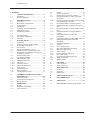
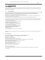
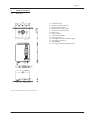
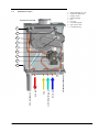
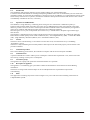
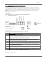
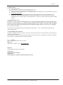
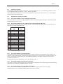
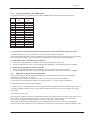
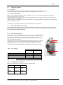
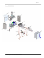
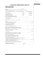
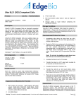
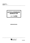
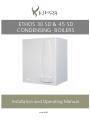
ETHOS 30 SD & 45 SD
CONDENSING BOILERS
Installation and Operating Manual
Issue 01/07
Combustion fan
CONTENTS
1
1.1
1.2
SAFETY GUIDELINES .............................1
Conditions .....................................................1
General guidelines.........................................1
2
2.1
2.2
2.3
2.4
2.5
2.6
2.7
2.8
2.9
2.10
2.11
TECHNICAL DATA ...................................2
Front view .....................................................2
Description of components............................3
Technical data................................................4
Introduction...................................................5
Operation of the ETHOS Boiler ....................5
Methods of control ........................................5
Combustion products ....................................5
.............................................5
Circulation pump...........................................5
Description of appliance ...............................5
Ethos SD........................................................5
3
3.1
3.2
3.3
3.4
3.5
3.6
3.7
INSTALLATION.........................................6
Unpacking .....................................................6
Selecting a location in the property ...............6
Suspending the appliance..............................6
Flue System...................................................7
Supply and discharge system ........................7
Influence of flue system on heat input ..........7
Classification according to evacuation of
combustion products .....................................8
Ethos resistance table ....................................9
Condensate discharge..................................10
CH and DHW circuit...................................10
Attention! Important....................................10
CH circuit....................................................10
Expansion Vessel.........................................10
Main Cold Water Inlet.................................10
Pump circuit ................................................11
Circulation pump.........................................11
Frost protection ...........................................11
Connecting the gas pipe ..............................11
3.8
3.9
3.10
3.10.1
3.10.2
3.10.3
3.10.4
3.11
3.11.1
3.12
3.13
4
4.1
4.2
4.3
ASSEMBLY INSTRUCTIONS FOR
ELECTRICIAN ........................................12
Mains connection ........................................12
Terminal block connections ........................12
Wiring diagram ...........................................13
5
5.1
5.2
5.2.1
OPERATION.............................................14
Display ........................................................14
Diagnosis mode display ..............................14
Control buttons............................................14
5.3
5.4
5.5
5.5.1
5.7
5.7.1
5.7.2
5.8
5.8.1
5.8.2
5.8.3
5.8.4
5.9
5.10
5.11
Sensors ........................................................15
Installer programme ....................................17
Explanation of options for installer.............17
Programme number J1: Max. CH supply
temperature .................................................17
Programme number J2: Max. CH heat output
(fan speed during CH mode) .......................17
Programme number J3: Pump operation .....17
Programme number J4: Pump CH overrun
time .............................................................17
Programme number J5: Pump DHW overrun
time .............................................................17
Programme number J6: Step modulation
Control ........................................................18
Programme number J7: Hot water
temperature .................................................18
Programme number J8: Max. DHW output 19
Filling and bleeding the boiler and
installation...................................................19
Starting the appliance..................................21
General........................................................21
First commissioning ....................................21
Heat input adjustment and setting ...............21
Max. heat input setting................................21
CO2 settings..............................................21
Checking the max CH input........................21
Min. input setting ........................................22
Conversion for different gas type................22
DHW temperature .......................................22
Shutting down .............................................22
6
6.1
6.2
FAILURES.................................................23
Cause of failure ...........................................24
Table of solutions ........................................26
7
7.1
7.2
7.3
MAINTENANCE ......................................28
General........................................................28
Inspection....................................................28
Maintenance................................................29
8
USER INSTRUCTIONS...........................30
9
EXPLODED VIEW ..................................31
10
PARTS LIST..............................................32
11
BENCHMARK commissioning checklist…34
5.5.2
5.5.3
5.5.4
5.5.5
5.5.6
5.5.7
5.5.8
5.6
Only original ETHOS parts must be used for service purposes.
Page 1
1
SAFETY GUIDELINES
1.1
Conditions
ETHOS BOILERS shall not be liable for any damages caused by non-compliance with the assembly instructions and
hence strongly recommend that these installation instructions are studied carefully. Only original ETHOS parts must
be used for services purposes.
1.2
General guidelines
It is a statutory requirement that all gas appliances are installed in accordance with the manufactures instructions and
all current regulations in force, all instructions should be fully read before installing or using the appliance.
All installations should be carried out by competent persons as described in the Gas Safety (Installation & Use)
Regulations. i.e. CORGI registered and holding current certification.
The work must be carried out by a competent person as described in the I.S. 813 Domestic Gas Installations with
reference to the following codes of practices.
The Manufacturers instructions MUST NOT be taken in any way as overriding statutory obligations.
This boiler has been tested and certified to comply with all necessary European directives, latest building regulations
and efficiency requirements for the SEDBUK scheme and as been approved with an efficiency band rating of A and
is CE marked and complies with
92/42/EEC Efficiency of Hot Water Boilers Directive
90/396/EEC Gas Appliance Directive
93/68/EEC Low Voltage Directive (was 73/23)
92/31/EEC Electromagnetic compatibility Directive
I.S. 813 Domestic Gas Installations
The boiler should be installed in compliance with
The building regulations (Scotland-consolidated)
Building Regulations (Northern Ireland)
Building Regulations
Water fittings regulations or water bylaws in Scotland
The boiler should not be modified in any way. Any modifications will invalidate the gas approval and invalidate the
warranty.
Codes of Practice
BS 7593:1992 Treatment of water in domestic hot water central heating systems
BS5546:1990 installation of hat water supplies for domestic purposes
BS5440 part 1: 2000 flues
BS5440 part 2: 2000 Ventilation
BS5449:1990 Forced circulation hot water systems
BS6798:2000 installation of gas fired hot water boilers of rated inputs not exceeding 70kW
BS6891:1989 Installation of low pressure gas pipe up to 28mm
BS7671:2001 IEE wiring regulations
BS4814:1990 Specification for expansion vessels
BS5482:1994 installation of LPG
BS7671 requirements for electrical installations
BS5955 -8 plastic pipe work installations
ATTENTION: High Voltage
Before opening the boiler casing for maintenance or servicing the 230VAC main supply to the boiler must be
disconnected!!
Page 2
2
TECHNICAL DATA
2.1
Front view
452
120
120
106
12
11
13
50
552
57
10
350
125
106
100
50 50
89
37
55
126
1+8
2
3
4
5
67
9
Figure 1 Dimensional sketch of CH boiler connections
1 = Condensate Trap
2 = CH Flow connection 22mm
3 = Gas connection 15mm
4 = DHW cylinder return 22mm
5 = CH return connection 15mm
6 = Drain Cock
7 = Pressure gauge
8 = Condensate discharge
9 = Cable glands (3x)
10 = Air supply (alternative 80mm 2 pipe)
11 = Air supply, concentric
12 = Flue discharge
13 = Air supply (alternative 80mm 2 pipe)
Page 3
2.2
Explanation of parts
1
2
3
4
5
6
7
8
9
Concentric terminal
1
2
3
4
5
6
7
8
9
= heat exchanger air vent
= high limit thermostat
= supply sensor
= heat exchanger
= fan
= air vent
= circulation pump
= gas control valve
= condensate trap
Condensate discharge
CH return
DHW cylinder return
Gas
CH flow
Condensate trap
Page 4
2.3
Technical data
General
EC product ID number
Dimensions (HxWxD)
Category
Type of appliance
CH water content of appliance
Weight (empty)
CH supply/return connections
DHW cylinder return connection
Gas connections
Flue connection
Air supply
Concentric
Power consumption
Power consumption, partial heat input
Power consumption, standby
IP-classification
Central heating
Nominal Heat Input (net)
Nominal Heat Input (gross)
Max. gas consumption
Efficiency at 50/30°C, full heat input
Efficiency at 50/30°C, partial heat input
Nominal heat output at 80/60°C
Nominal heat output at 50/30°C
Sedbuk rating
NOx-emission
CO- emission
Technical data
Max. flue gas volume
Boiler class (evacuation /air supply)
Flue gas CO2 content
Flue gas dew point
Flue temperature at 80/60°C (at ambient temperature of 20°C)
Flue material temperature class
Permitted maximum resistance of flue system *
Condensation pH value
Available CH pump pressure at ∆T20°C (in meter Water Gauge)
Max. CH supply temperature
CH water pressure (min./max.)
NOx class
Required gas pressure (Natural Gas G20 )
( LPG G31)
mm
litre
kg
mm
mm
mm
mm
mm
mm
W
W
W
kW
kW
m³/hr
%
%
KW
KW
mg/kWh
mg/kWh
m3/hr
%
°C
°C
Pa
MWG
°C
Bar
mbar
mbar
CE 0063 BQ 3034 (2005)
550 x 450 x 350
II2L3P
Ethos 45SD
Ethos 30SD
2,1
30
22
22
15
80
80
80/125
180
100
5
IP44
2,7
32
22
22
15
80
80
80/125
200
135
5
IP44
6,6 – 28,5
7,3 – 31,7
3,0
105,0
108,1
6,3 – 27,6
7,1 – 29,9
A
<15
<20
9,9 – 42,5
11,0 – 47,2
4,5
105,4
108,5
9,6– 41,1
10,7– 44,8
A
<15
<20
60,0
40,0
B23, C13, C33, C43, C53, C63, C83
9
52
75
T 120
150*
4 tot 5,5
2,0
1,5
90
0,5 – 3
5
5
10 - 25
30 - 50
Table 1 Specifications
* With this resistance value the heat output will remain within the specifications indicated on the data plate; if the
.
resistance is higher, the heat output will drop, see par3.6
Installation and Operation manual ETHOS 36C and ETHOS 54C –1206/06
Issue 2
Page 5
2.4
Introduction
This Installation and Operating manual is for the installer and the user of the ETHOS boiler.
It contains essential information for installing and adjusting ETHOS boilers. We recommend that you first consult this
installation manual, to ensure that the installation is carried out correctly. In addition, it is required that the end user of the
boiler be fully instructed on its operation, and that the installation and operation manual be left near the boiler to make
it immediately available for later use, if necessary.
2.5
Operation of ETHOS Boiler
This ETHOS; is a high efficiency, condensing, boiler. Flue gases are cooled below condensation point by a
Spiranox heat exchanger made of stainless steel. This recovers additional heat which will contribute to the boiler
efficiency, which is in excess of 107%. The European calculation method assumes 100% efficiency for appliances
which do not condense and efficiencies higher than 100% for condensing appliances.
Since flue gases are very low in temperature (lower than 75°C), a stainless steel or PP plastic approved flue pipe
must be used.
The appliance is manufactured in according with the European approved requirements (EC) and has the following
Dutch Gastec Gaskeur quality marks: Clean combustion (SV) – 107% High Efficiency (HR) – Comfort Hot Water
(CW) –,High Efficiency Hot Water (HRww) and – Solar Boiler Reheater (NZ).
2.6
Control
The boiler can be controlled using a conventional volt free time clock, room thermostat or by a modulating
‘OpenTherm’ control.
The boiler is fully modulating and accurately balances heat output to the load of the property and for the hot water
production demand.
2.7
Combustion products
Due to the modulating premix burner, the combustion complies with the strictest European standards.
2.8
Combustion fan
A speed-controlled fan is used to reduce power consumption: when the heat requirement is low, the fan will rotate
more slowly, resulting in lower power consumption.
2.9
Circulation pump
The appliance has a pump with speed switch which should be set at speed III
2.10
Description of appliance
The appliance is a ccondensing gas system boiler suitable for both domestic and commercial Central Heating
installations.
The boilers are range rated. The heat output can be set and adjusted to the requested heat output of the
central heating.
2.11
Ethos
This appliances are heating only boilers with an integral 3 way valve and control unit including connections for
a Rapide DHW cylinder.
Page 6
3
INSTALLATION
246
246
552
3.1
Unpacking
This appliance is supplied with:
− Installation and Operating manual;
− a user manual with warranty card;
− a air vent key;
− a hanging bracket;
− Condensation trap with condensate discharge hose.
Check the appliance immediately on receipt.
Any damages must be reported to the supplier immediately.
All appliances are completely assembled.
Ethos condensing boilers are adapted to natural gas G20
3.2
Selecting a location in the property.
The front and bottom side of the appliance have to be accessible
for maintenance and service.
20
452
20
Figure 2 Dimensional sketch of clearances
Both sides must be placed at least 20 mm from the wall or cabinet wall.
452
226
170
226
170
12,5
57
The following facilities must be present and readilty available:
a) A permanent 230 volt single phase power supply with the boiler being
protected by a double pole switch with minimum openings of 3mm
and fused at 3 amp.
b) Drain connection suitable for condensate discharge.
c) Wall which can support the boiler weight.
8x15
Ø8
8x15
552
The assembly location should be dry and protected from adverse weather
conditions such as frost and freezing.
The appliance has a built-in fan which will causes low levels of noise depending
on the load: choose a location in the property where this sound production will
not cause nuisance, preferably against a brick wall.
12,5
3.3
Suspending the appliance
Mark off the holes for the hanging bracket and determine the location for
connecting the supply and discharge pipes.
Figure 3 Dimensional sketch of wall bracket
Page 7
3.4
Flue System
General
Air supply material: PP plastic or stainless steel
Flue discharge material: plastic (temperature resistant up to 120° C, air flushed) or stainless steel with sealed joints.
Attention!
First connect all pipework and flue pipes, fill up and vent the installation before commissioning the boiler.
The high flue gas temperature protection for plastic discharge material is built into the boiler as a safety feature. This
protection cuts off the gas supply as soon as the preset maximum flue temperature is exceeded, after which the
appliance is interlocked and error code 't0' starts to flash.
There are two types of connections
• Concentric connection (80mm / 125mm with one pipe inside the other)
• Two Pipe system (80mm air intake with a separate 80mm Flue outlet)
Concentric connection (standard)
The concentric connection kit is standard: diameter air supply pipe 125 mm and flue pipe 80 mm.
Always ensure that the grey plastic adaptor is sited in the flue connection correctly before installing the connecting
flue pipework
Two Pipe System (optional)
The optional connection for air supply and flue pipes is suited to a stainless steel or plastic discharge
system.
The connection diameter for the flue pipe is 80 mm and for the air supply pipe also 80 mm.
The air supply pipe can be placed on the left or right side of the flue pipe by moving the connection sockets.
3.5
Supply and discharge system
The Ethos boiler is a room sealed appliance with the air needed for combustion being drawn in from outside. The
casing jacket is sealed airtight to the back plate, so the air can only be supplied through the air supply pipe. Therefore,
always make sure that the front door is correctly fitted on the appliance when the boiler is operating.
Attention!
Note that any horizontal flue pipe must incorporate a fall sloped back toward the boiler at a rate of 10mm per 1 metre.
If not,condensation can accumulate in the flue pipe, and may result in water damage to the boiler.
3.6
Influence of flue system on heat input
The diagram shows the ratio between the kW input and the flue systems resistance. For the maximum
Boiler output a maximum resistance of 150 Pa or less is required.
Should the flue resistance be more than 150Pa the boilers output will be reduced; for further information contact the
technical department.
60
DHW heat input (Net) [kW]
CH heat input (Net) [kW]
55
50
45
30SD
40
45SD
35
30
25
20
0
50
100
150
200
250
300
Pressure drop [Pa]
350
400
450
500
Diagram 1 influence of pressure loss on heat input
Page 8
3.7
Class
B23
C13
C33
C43
C53
Classification according to evacuation of combustion products
System description
• Non-room sealed application; flue connected
to outside but combustion air is being drawn
directly from room where boiler is installed.
• Room sealed premix appliance with
horizontal outlet
• Air intake and flue gas discharge through
concentric exterior wall terminal
• Room sealed premix appliance with vertical
outlet terminal
• Air intake and flue gas discharge through
concentric exterior roof terminal
• Room sealed premix appliance with
collective supply and discharge
•
Comments:
• Appliance complies with Class C
• Max. back pressure 1mbar (100Pa)
•
•
•
Type exterior wall duct
Max. resistance 150 Pa
Ducts sloped to drain toward boiler (1cm/m)
•
•
Type roof duct
Max. resistance 150Pa
•
•
•
Room sealed premix appliance with separate •
supply from exterior wall and separate
discharge through roof
•
•
•
•
C63
•
C83
•
Room sealed premix appliance with separate •
approved and marketed system
•
Room sealed premix appliance with separate •
supply from exterior wall and collective
•
discharge
•
Vertical terminal
Max. resistance 150Pa
Ducts sloped to drain toward boiler (1cm/m)
Collective discharge with under pressure
Air terminal not provided by boiler
manufacturer
Roof terminal not provided by boiler
manufacturer
Max. resistance 150Pa
Ducts sloped to drain toward boiler (1cm/m)
Supply and discharge to be installed on the
same side of the building
Only connect to UK approved discharge
material
Max resistance 150Pa
Type exterior wall duct not provided
Max. resistance 150Pa
Ducts sloped to drain toward boiler (1cm/m)
Horizontal terminaL
Page 9
3.8
Ethos resistance table
By using different flue installations, either concentric or the 2 pipe system different flue lengths can be achieved, Up
to a resistance of 150 Pa. At this pressure the heat input will be equal (±5%) to the heat input specified on the data
plate of the appliance. When a concentric system is used, its length should not exceed 12 meters, this is not due to
resistance but to the preheating of the combustion air.
Concentric Flue System
Part
(mm) Component Resistances [Pa]
ETHOS 30SD ETHOS 45SD
Vertical Terminal
Horizontal Terminal
straight pipe/m
45° bend
90° bend
80/125
80/125
80/125
80/125
80/125
12
23
3,4
2,6
3,9
26
50
7,4
5,7
8,5
80
1,1
2,3
45° bend R=0,5D
80
1,3
2,8
90° bend R=1,0D
80
2,1
4,5
80
80
80
12
36
1,4
26
50
2,9
45° bend R=0,5D
80
1,6
3,5
90° bend R=1,0D
80
2,5
5,4
Two Pipe System
Air Inlet
Part
straight pipe/m
Flue Gas Outlet Vertical terminal
Horizontal terminal
straight pipe/m
Table 3 Flue discharge resistance
Example of calculation
boiler type: Ethos 45SD
Concentric pipe 80/125mm vertical 5m + horizontal 1m=total 6m concentric straight pipe
2x Concentric 90° bend ;
2x Concentric 45° bend ;
Vertical terminal 80/125.
Concentric pipe 80/125: 6m
Concentric 90° bends : 1 pieces
Concentric 45° bends : 2 pieces
Vertical terminal 80/125
Total Resistance
6 x 7,4
1 x 8,5
2 x 5,7
Resistance
44,4 Pa
8,5 Pa
11,4 Pa
26,0 Pa
90,3 Pa
Total resistance is 90,3 Pa, so the boiler output is not changed by the resistance (lower than 150 Pa) and total
concentric length is less than maximum allowed 12 metres.
Page 10
3.9
Condensate discharge
The condensate discharge must be installed during the assembly. Install the condensate discharge as follows:
Slide the supplied cup bottle trap over the two condensate hoses under the boiler, so the arrows are facing each
other. Then push the cup against the bottom of the boiler.
Turn the trap in position until the condensate discharge faces the desired direction. Attach the condensate discharge
hose to the trap with a plastic swivel and seal. The connection is linked to a suitable drain via the flexible hose.
Only use plastic parts for the condensation discharge. Metal pipes will corrode and are not acceptable.
Attention!
If this discharge is blocked, the appliance may be damaged.
3.10
CH and DHW circuit
Figure 4 CH boiler piping connections
=
3.10.1 Attention! Important
If plastic central heating pipe is used on the system, it should be
barrier protected against oxygen diffusion.
On existing installations, the system should be fully cleaned and
flushed, with a suitable strainer being installed in the return pipe work
before being connected to the boiler.
3.10.2 CH circuit
The feed and return connections are based on connecting the
installation by using compression fittings.
These connections are located at the bottom of the appliance.
It is essential to install the isolation valves which are suppiled. The
appliance has a drain cock at the bottom, so it can be easily drained.
2
1
=
3
4
5
9
6
1= Condensate trap
2= CH & DHW primary flow
3= Gas
4= DHW primary return
5= CH return
6= Drain Cock
7= Pressure gauge
8= Cable glands 3 x
9= Condensate trap outlet
ATTENTION ! ( Safety Relief Valve )
The appliance is not equipped with a prefitted pressure relief valve; A
suitable valve with a max. 3 bar setting must be installed in the installation's pipe work, in the immediate vicinity of
the appliance.
ATTENTION ! ( System Bypass )
The appliance is not equipped with an internal bypass. A suitable automatic bypass valve should be fitted in
accordance with current regulations, and at such a distance from the boiler as to allow suitable flow rates.
Before the installation is operated for the first time, it must be thoroughly flushed and treated with suitable system
cleaners and inhibiters.
3.10.3 ATTENTION ! ( Expansion Vessel )
The boiler is not fitted with an internal expansion vessel; so an expansion vessel should be sized to suit the volume
of water in the central heating installation and static pressure. The expansion vessel should be connected to the
return pipe work. Please contact our technical department for advise on expansionvessel sizing.
8
7
Page 11
3.11
Pump circuit
Depending on the boiler version, several types of pumps can be found inside the appliance; a built-in Grundfos UPS
15-60 HB pump(Ethos 30 SD only) or a Grundfos UPS 15-70 HB pump (Ethos 45SD only).
3.11.1 Circulating pump
The pump has a speed switch which is factory-adjusted to the
highest position.
Position
Attention!
The pump speed should not be adjusted
The appliance has a built-in pump overrun timer.
Ι
ΙΙ
ΙΙΙ
Ethos 30SD
X
Right
Right
Ethos 45SD
X
X
Right
3.12
Frost protection
The boiler has a built-in frost protection for activating the central heating pump when the boiler water temperature is
8°C. When the boiler water temperature is 5°C, it will also ignite the burner until the supply temperature is 10°C.
Attention!
Any other parts of the installation that may be subjected to frost or freezing should have additional protection fitted.
3.13
Connecting the gas pipe
At the planning stages it may be necessary to contact the local gas supplier to ensure an adequate supply of gas is
available.
An existing service pipe must not be used without first contacting the local gas supplier.
All gas pipe work should be installed by a competent person and in accordance with all current standards and
regulations.
The boilers gas pipe should be calculated and sized to supply adequate gas working inlet pressure of 20mbar
(minimum) for natural gas and 30mbar (minimum) for LPG.
All gas pipe work should be tested for gas tightness.
Installation and Operation manual ETHOS 36C and ETHOS 54C –1206/06
Issue 2
Page 12
4
ASSEMBLY INSTRUCTIONS FOR ELECTRICIAN
4.1
Mains connection
The boiler requires an earthed 230 volt 50 Hz single phase supply and must be connected in accordance with all
current regulations and requirements. A permanent supply to the boiler is needed at all times to the boiler, which
should be protected by a maximum 3 Amp double-poled isolator with at least 3mm of contact separation on both
poles.
The single phase cable colour coding should be wired correctly, although the boiler is not polarity sensitive
All control switching is volt free.
ATTENTION!
AT NO TIME SHOULD 230 VOLT BE USED TO SWITCH THE BOILER.
PC
COM
Cylinder Sensor
Outside Sensor
Timeclock or
room thermostat
Terminal block connections
Opentherm
control
4.2
12345678
PE N L
FUSE 2AT
CODE KEY
N L
ALARM
Figure 6 Electric terminals
The following parts can be connected to the terminal block, see illustration
PC COM
1-2
3-4.
5-6.
7-8
PE. N. L
CODE
KEY
ALARM
PC communication. The manufacturer can use this connection for reading-out or modifying data or
settings by using a PC and connecting cable.
OpenTherm control. Can be used to fully modulate the boiler.
On/off room thermostat / time clock. For connecting clock or conventional room thermostats. The
heat acceleration element of the on/off thermostat must be set at 0.12A; the max. permissible
resistance of the room thermostat circuit should not exceed 10 ohm.
Attention! Do not connect an OpenTherm control to this terminal.
Outside temperature sensor. If an OpenTherm control with weather dependent control is
used, the outside temperature sensor must be connected to terminals 5 and 6. The OpenTherm
control contains the settings for weather dependent control.
External DHW cylinder. The external water heater can be connected to the boiler with a sensor
(NTC) or thermostat; if a sensor is used, the boiler display can show the water heater temperature.
Only applicable for Ethos …SD boilers
Power supply connection 230V. Connection for earthed cable.
PE= earth N= Neutral L= phase 230V 50Hz
Code key. A code key is a small PCB which contains the settings per boiler type. When the burner
control unit is replaced, the code key must be installed in the new burner control unit.
External failures. This connection can be used for showing external messages by using a relay on
terminals 1 and 3. A LED can be connected to terminals 2 and 3.
Table 4 Explanation of electrical connections
Page 13
Wiring diagram
See Diagram 4.2
4.3
Page 14
5
OPERATION
5.1
Display
The display has two digits, which indicate the supply temperature of the central heating water in the boiler:
By pressing the Info button, the operating status can be displayed. If the Info button is pressed twice, the display will
show the water temperature of the central heating water. If the display shows a code that starts with a (t), the boiler
will temporarily shut down, except for code t4 and t5. If these are active, the boiler will run an emergency
programme. If a (t) condition is automatically restored, the boiler will operate normally again.
.0 Standby
.2 Fan start
.3 Fan pre-purge
.4 Ignition
.5 CH mode heat demand or CH pump overrun
.6 DHW operation
.7 DHW preheating or DHW pump overrun
t0 High limit thermostat >opened 30sec.
t1 Supply temperature too high during CH demand or anti-recycle timer
t2 Supply temperature too high during hot water mode
t3 Hot water temperature too high
t4 Supply sensor interrupted / short-circuited
t5 N/A
t7 Room thermostat anti-recycle timer active
t8 Vent programme active
t9 VKK check error None UK code
tc Temperature Delta-T during start too low
Figure 1 Display
5.2
Diagnosis mode display
In this menu various current settings and the last 10 failures or interlocks can be consulted, without using a laptop.
If no failures are saved in the burner control unit memory, the display shows ’- -’.
By pressing the ’-’ button (approx. 1 sec.), the diagnostic menu is shown. By pressing the Info button, the following
information is shown:
D1 = current supply temperature
D2 = domestic hot water temperature
D3 = N/A
D4 = outside temperature
D5 = N/A
D6 = pump on 1 /pump off 0
D7 = three-way valve position C = CH / T = DHW
D8 = ionisation current (micro Amp)
D9 = not active
E0 = --last failure … E1--E9= other stored failures
5.2.1
Control buttons
These buttons give access to different options for adjusting and checking the appliance; by pressing a button or a
combination of buttons, the following functions can be performed:
1. Switching DHW production on or off
By pressing the ’+’ button (3 sec.), the DHW function can be activated.
H1/ - - alternately shown on display: DHW is switched off.
H1/ t a alternately shown on display: DHW is switched on.
By pressing the Info button again, a selection can be made between the Eco or Comfort mode for keeping the
internal DHW heat exchanger warm.
Page 15
2. Installer menu:
To access the Installer menu.
First press the ’-’ and ’Info’ buttons simultaneously (3 sec.).
After pressing these buttons, the window will show a ’0’.
Then enter code ’8’ by using the ’+’ or ’-’ buttons and press the Info button to access the Installer menu (see
5.4 Installer programme).
Exit this Installer menu by pressing the Info button until the display shows the central heating water
temperature. Then the modified parameters will be automatically saved. If you do not wish to save the
modifications, wait 1 minute and you will automatically exit this service menu without saving the modified
settings.
3. Adjusting the gas valve:
Pressing the ’–’ and ’+’ buttons simultaneously (3 sec.) = Gas valve adjusting mode for 20 minutes, (display shows
an ’H’ or ’L’). By pressing the ’+’ or ’–’ buttons again, the high and low setting speeds can be accessed. The display
alternately shows the speed in thousandths (Ethos 30SD= H 6000/6.0 rpm L 1500/1.5 rpm Ethos 45SD= H 6000/6.0
rpm L 1650/1.6 rpm) and an ’H’ for max CH output. The display alternately shows an ’L’ and e.g.1.5 (1,500 rpm)
for the minimum CH output.
Cancel the gas valve adjusting mode by simultaneously pressing the ’+’ and ’–’ buttons and the appliance will
operate automatically.
4. Programming with a computer:
The boiler is equipped with a pc-interface. The boiler control unit of the boiler can be linked to a pc using a special
cable interface and software
This option can be used to read-out information from the burner control unit or programme new settings or updated
boiler software. Contact Mikrofill for further information.
5.3
Sensors
The following temperature sensors are used:
10K NTC:
supply sensor (Number: 36, par 9 Exploded view)
12K NTC:
outside temperature sensor (if installed)
Temperature
Sensor 10 K NTC resistance
Temperature
Sensor 12K NTC resistance (outside temperature sensor)
Installation and Operation manual ETHOS 36C and ETHOS 54C –1206/06
Issue 2
Page 16
Table 5 Resistance table for sensors
Resistance
Resistance
Temperature
sensor
Temperature
[°C]
10K NTC
[°C]
[Ohm]
sensor
12K NTC
(outside temperature sensor)
[Ohm]
0
32550
-30
171800
5
25340
-25
129800
10
19870
-20
98930
15
15700
-15
76020
20
12490
-10
58880
25
10000
-5
45950
30
8059
0
36130
35
6535
5
28600
40
5330
10
22800
45
4372
15
18300
50
3605
20
14770
55
2989
25
12000
60
2490
30
9804
65
2084
35
8054
70
1753
40
6652
75
1481
45
5522
80
1256
85
1070
90
915
95
786
High limit thermostat:
In addition, the appliance has a high limit thermostat which is placed on top of the distribution pipe, on the right side
of the stainless steel exchanger (Number: 11-1, 9 Exploded view).
Page 17
5.4
Installer programme
If the installer code is entered (after pressing the ’-’ and ’Info’ buttons for 3 sec.), the following parameters can be
set or modified (modify by using the ’+’ and ’–’ buttons). See table 7.
After modifying the parameters, you can exit this programme by pressing the ’Info’ button (3 sec.). The modified
settings will be saved automatically.
5.5
Explanation of options for installer
5.5.1
Programme number J1: Max. CH supply temperature
This option is used to set the max. supply temperature of the central-heating boiler during the central heating mode.
Settings range from 10°C to 90°C.
5.5.2
Programme number J2: Max. CH heat output (fan speed during CH mode)
This option can be used to increase or decrease the max. central heating heat output (40/30°C) as specified on the
data plate, according to the table below:
99%
95%
90%
85%
80%
75%
70%
65%
60%
55%
50%
45%
40%
35%
30%
Ethos 30SD
kW
30
28
27
25
24
22
21
19
18
16
15
13
12
10
9
Ethos 45SD
kW
45,0
43
41
38
36
34
32
29
27
25
23
20
18
16
14
Table 6 CH heat output
5.5.3
Programme number J3: Pump operation
This option is used to select a continued central heating pump circulation for the installation. This setting has no
influence on the continued pump circulation after tapping hot water: this overrun time is recorded in parameter ’J5’.
Enter '0' for the pump overrun time for the central heating installation. The length of the pump overrun time is
recorded in parameter ’J4’.
If the pump must operate continuously (e.g. for floor heating), enter ’1’.
5.5.4
Programme number J4: Pump CH overrun time
This option is used for setting the pump overrun time after the heat demand for central heating has finished. Settings
range from 0 to 30 minutes; the default setting is 3 minutes.
5.5.5
Programme number J5: Pump DHW overrun time
This option is used for adjusting the pump-overrun time after heating up the built-in hot water supply.
Settings range from 0 to 30 minutes; default pump overrun time is 1 minute.
Page 18
Programme
number
Programme description
Setting range
Default setting
*J1
*J2
*J3
Installer code
Max. CH supply temperature
Max. CH heat output
Pump operation
Installer code is 8
85°C
80%
0
*J4
*J5
*J6
Pump overrun time for CH mode
Pump overrun time for DHW mode
Step modulation
*J7
*J8
DHW temperature
Max. DHW heat output
0 – 99
10°C – 90°C
30% - 99%
0 = pump overrun time active
1 = pump continuous
0…30 min.
0…30 min..
0= Step modulation, CH off
1= Step modulation, CH active; 5
minute steps
2= ditto, 10 minute steps
3= ditto, 20 minute steps
55°C - 65°C
30% - 99%
3 min.
1 min.
1
60°C
99%
Table 7 parameter settings
5.5.6
Programme number J6: Step modulation Control
This parameter can be used to increase the heat output in steps while heating the installation, so the appliance is
condensing continuously, generating a high efficiency. This step programme consists of 6 steps, each with an
adjustable interval:
J6- 0 = no steps, so on/off, based on the room thermostat
J6- 1= 6 steps, each with a 5 minute interval (factory setting)
J6- 2= 6 steps, each with a 10 minute interval
J6- 3= 6 steps, each with a 20 minute interval
With each step the heat output is increased with 20%, starting with the min. heat output.
The boiler will start with the lowest heat output and increase this with 20% every ’5, 10 or 20’ minutes until the
max. heat output is reached or the boiler ends this programme because the installation has reached the set
temperature.
a. When using an on/off room thermostat:
If there is no heat demand, this programme will count backwards with the same intervals until a renewed heat
demand is present; the appliance will then start with a heat output corresponding to the deducted interval.
Consequently, the boiler efficiency during heating will always be higher than 100% and the boiler will always have
an optimal heat output during the daytime period. This prevents undesirable fluctuations of the room temperature.
b. When using an ’OpenTherm’ control
If the calculated water temperature of the thermostat is reached, the step programme will be stopped and the
’OpenTherm®’ thermostat will take over the boiler control. The boiler heat output is adjusted to the heat
requirement: the boiler will modulate optimally and a steady room temperature will be maintained
5.5.7
Programme number J7: Hot water temperature
Use this parameter to adjust the hot water temperature of the tap water between 55 – 65°C.
Warning!
Do not set DHW temperature lower than 60°c for anti legionella purposes.
Page 19
5.5.8
Programme number J8: Max. DHW output
This parameter enables you to adjust the heat output for DHW. Based on flow/return temperatures 80/60
99%
95%
90%
85%
80%
75%
70%
65%
60%
55%
50%
45%
40%
35%
30%
Ethos 30SD
kW
28
27
25
24
22
21
20
18
17
15
14
13
11
10
8
Ethos 45SD
kW
41
39
37
35
33
31
29
27
25
23
21
18
16
14
12
1. An ‘OpenTherm’ control with a built-in outside temperature control and outside temperature sensor
Connect the OpenTherm control to terminals 1 and 2 of the terminal block in the boiler.
Connect the outside temperature sensor to terminals 5 and 6 of the terminal block in the boiler. Except for adjusting
the combustion line, which is pre-programmed by the manufacturer, no parameters have to be modified.
2. Connecting a room or clock thermostat to the boiler
• Connect the room thermostat to terminals 3 and 4 of the terminal block in the boiler.
• Except for adjusting the values pre-programmed by the manufacturer, no parameters have to be modified.
3. Connecting an ‘OpenTherm’ control to the boiler
•
Connect the OpenTherm® thermostat to terminals 1 and 2 of the terminal block in the boiler.
•
Except for adjusting the values pre-programmed by the manufacturer, no parameters have to be modified.
5.6
Filling and venting the boiler and installation
Fill the central-heating boiler and heating installation by using the filling and drain cock in the installation.
The filling pressure must be 1 to 1.5 bar.
The following points must be considered to prevent corrosion of the central heating installation:
a. The CH system water should be treated to give neutral pH value, +/-7. Only use approved additives.
b. Thoroughly flush the central heating installation
c. If plastic pipes are used, they must be of an oxygen diffusion barrier and be suitable for central heating systems, in
according with DIN 4726/4729. If they are not, make a separation between the boiler circuit and the circuit with
plastic pipes.
d. Check the circuit for leaks.
After filling the installation and boiler, bleed the heat exchanger once before the first commissioning. To do so, open
the air vent on the upper left side one full turn. As soon as water starts to pour out of the vent, close it again.
The wall boiler is equipped with an automatic air vent at the top of the circulation pump.
Shortly after commissioning the appliance, check the filling pressure. If necessary, add water to maintain the
required pressure. The wall boiler's electric control has a special start-up programme for venting the appliance. This
Page 20
programme is started when the power supply is switched on for the first time or when pressing the Info button after
a failure.
This start-up programme takes 2 minutes: the display shows code ’t8’. After the venting programme has finished,
the boiler will start to operate.
Shutting down the appliance
1. Isolate the boiler from the electrical supply and close the gas tap.
2. When shutting down the appliance because of frost risk, drain the central-heating boiler and installation. To do so,
open the filling and drain cock of the central heating installation and the boiler drain cock at the lower right side of
the appliance. In case of frost risk, also drain the water pipe.
Page 21
5.7
Starting the appliance
5.7.1
General
The initial pressure in the gas pipe can be measured with the gas control valve measuring nipple (3).
The minimum initial pressure for the proper operation of the appliance must be 10 mbar.
5.7.2
First commissioning
When you have tested the installation and everything is in order, you can insert the plug of the central-heating
boiler's mains cord into the wall socket.
When the appliance is connected to the mains, the double display will show the supply temperature and the single
display the status of the appliance.
After the appliance is connected to the mains, an automatic air venting programme for the boiler will be started. This
will take approx. 2 minutes.
Use the screw [3] on the gas control valve for measuring the initial gas pressure.
5.8
Heat input adjustment and setting
Adjust the boiler heat input by measuring the CO2 percentage when checking or installing a new gas control valve.
By measuring the CO2 percentage, both the min. and max. heat input can be adjusted. First adjust the max.
heat input and then the min. heat input.
5.8.1
Max. heat input setting
Pressing the ’–’ and ’+’ buttons simultaneously (3 sec.) = Gas valve adjusting mode
for 10 minutes, (display shows an ’H’ or ’L’). By pressing the ’+’ button, the high
position speeds can be accessed. The display alternately shows the speed in
hundreds (Ethos 30SD= H 6000/6.0 rpm L 1500/1.5 rpm Ethos 45SD= H 6000/6.0
rpm L 1650/1.6 rpm) and an ’H’.
If required, the max. input can be adjusted by using the adjusting screw [2]. Turning
the adjusting screw to the left (anticlockwise) will increase the max. heat output.
Turning the adjusting screw to the right (clockwise) will reduce the max. heat
output (see arrows under the adjusting screw). Adjust the max. input, if necessary
5.8.2
CO2 settings
Injector
Wobbe index (Ws )(gross) (MJ/m3)
Calorific value (net)
(MJ/m3)
CO2 max.input
(%)
Type of gas
Natural gas
Propane
G20
None
None
50,72
76,64
34,02
88,00
8,8(+/-0,3)*
10,5(+/-0,3)*
* Measured without front casing
Table 8 Gas settings
5.8.3
Checking the max CH input
Measured for natural gas or propane according to the table below:
Appliance
Ethos 30SD Ethos 45SD
Natural gas
50 litre in
54 sec.
50 litre in
35 sec.
Propane
15 litre in
46 sec.
15 litre in
30 sec.
Installation and Operation manual ETHOS 36C and ETHOS 54C –1206/06
Issue 2
1
2
3
Page 22
Note: After adjusting with a CO2 % measurement, the gas meter can be used to check if the required input is
reached.
5.8.4
Min. input setting
After setting the max. input, press the ’–’ button. The display alternately shows the lower position min. speed which
is 1.5 or 1.7 (= 1,500 rpm Ethos 30SD and 1,650 rpm Ethos 45SD), depending on the applied type, and an ’L’.
Turn the screw [1] for the min. setting to adjust this min. input.
Note: When adjusting the CO2 percentage, turn the adjusting screw only slightly.
The CO2 percentage will be reduced if the screw is turned anticlockwise and increased if turned clockwise
Injector
Wobbe index Ws (gross)
Calorific value Hi (net)
CO2 min. heat input
(MJ/m3)
(MJ/m3)
(%)
Type of gas
Natural gas G20
Propane
None
None
50,72
76,64
34,02
88,00
8,3(+/-0,3)*
10,1(+/-0,3)*
* measured without front casing
Cancel the gas valve adjusting mode by simultaneously pressing the ’+’ and ’–’ buttons and the appliance will
operate automatically.
5.9
Conversion for LPG
Please contact ETHOS Boilers before converting the appliance for LPG use.
After conversion to propane, the CO2 settings must be checked:
a. Turn screw [2] 4 full turns clockwise.
b. Switch on the appliance. If appliance doesn’t fire after 4 ignition attempts , turn screw [2] one full turn
back (anticlockwise).
c. If burner is ignited: press (approx 1 minute after ignition) the ‘-‘ and ‘+’buttons simultaneously (3 sec).
Boiler will now operate for 20 minutes in gas valve setting mode.
d. Check / set max. and min. heat input and CO2 setting according to par. 5.8.1 to 5.8.4.
e. When combustion has been set please ensure that parameters J2 & J8 in the installer program are set at
less than 95% ( see paragragh 5.4 - 5.5.8 )
f. Attach the sticker ‘set for propane 3P G31 - 50 mbar ’next to the data plate on the underside of the boiler.
5.10
DHW temperature
This temperature is set by the manufacturer at a fixed value of 60°C to prevent Legionella contamination at low
temperatures.
It is advisable not to set this temperature at a lower value.
5.11
Shutting down
It is advisable to keep the appliance switched on during winter and summer. This prevents the appliance from
freezing and moving parts from seizing.
Switch off the appliance by decreasing the value of the room thermostat: this ensures a minimum power
consumption (+/- 5 watt), since the central heating pump and fan will stop after a short time delay.
If it is necessary to shut down the appliance, perform the following actions:
a. Close the gas tap.
b. isolate the boiler from the electrical supply.
c. In case of frost risk, drain the appliance and installation.
d. In case of frost risk, also drain the water pipes.
First drain the installation and then open the draining point on the boiler to drain the appliance.
Page 23
6
FAILURES
There are a number of situations during which the appliance will shut down due to a failure and can only be activated again
by pressing the Info button. Failures are indicated by a flashing dot behind the water temperature in the lower right side
corner of the display. By pressing the Info button, the failure will be shown briefly and the boiler will automatically start
operating again.
The following 'lock-out' failures can occur. A flashing F followed by a digit on the display shows the type of failure.
Display code:
Failure description:
Blank
F0
Power supply failure
High limit thermostat opened
F1
F2
Code key error
Manually generated boiler failure for
programming with computer
Ionisation failure
Ionisation during rest
End of programming
Fan error
N/A
Failure of burner control software check and/or
problem with mains supply frequency
F4
F6
F7
F8
F9
FH
Cause of failure
(see table 11):
14;20;27;36;37;38;50
4;5;21;23;24;29;30;31
42;43;46;47
13;63
15;63
10;11;16;17;18;22;25;35;34
18;35;61
48
7;8;9;13;19;39;40;41
Table 9 Failures
Display code:
t messages
Failure description :
Temporarily blocked
Cause of failure
See section. 5.1.
Page 24
In addition, there are a number of failures or problems which cannot be shown on the display.
Below a number of these failures or problems are listed:
Table 10 Other types of failures
Symptom
a
b
c
d
e
f
g
h
i
j
k
l
44.1
Room temperature not reached, appliance does fire
Noisy ignition
Boiler runs continuously but CH water does not warm up
Room thermostat demands heat, but boiler does not ignite
Boiler firing continuously, house too warm
Boiler is very noisy in CH operation
Top of radiators not getting hot enough
Water drawn off but water from the hot tap remains cold
Domestic Hot water much too hot
Water is drawn off, but the water from the hot tap does not reach 60°C
Boiler very noisy during DHW operation
Fault after replacement of burner control unit
Cause of failure
(see table 11):
45 ;53 ;54
35
45
1;42;52
2
29;46;66
55
24;56
51;57
51
23
60
Cause of failure
Table 11 Cause of failure
Failures can be caused the following:
1.
Room thermostat is not connected properly.
2.
Room thermostat does not switch off, short circuit in cable.
3.
Sensor has caused a short circuit in the cable or internally.
4.
Pump does not rotate; is stuck.
5.
Water pressure in central heating installation is too low.
6.
Water pressure in central heating installation is too high.
7.
Fan is not connected (plug is not connected).
8.
Fan is dirty.
9.
Fan is defective.
10. Gas tap is not turned on.
11. Gas pressure is too low.
12. Gas pipe diameter too small.
13. Code key not installed; code key not connected properly to burner control unit; wrong type of code key.
14. Fuse defective.
15. This code is shown after programming with a PC.
16. Gas valve setting at lowest speed is wrong.
17. Gas valve is not or not properly connected electrically.
18. Ignition cable interrupted or not connected properly.
19. Transformer defective.
20. Gas valve connector not fitted properly or moisture inclusions.
21. Pump connector not fitted properly.
22. Siphon clogged.
23. Air in system; open and close manual bleeder after bleeding.
24. Three-way valve is dirty.
25. Resistance in the discharge system too high or discharge system dirty.
26. Discharge system is leaking toward supply system; flue recirculation only at concentric connection.
27. Supply system lets in water.
28. N/A
29. Heat exchanger interior is dirty (insufficient circulation)
30. High limit thermostat defective (insufficient circulation)
31. Max. heat input too high.
34. Burner control unit defective.
Page 25
35.
36.
Ignition electrode defective (porcelain cracked); wrong distance to burner
Moisture on gas valve cables or ignition cable.
37.
38.
39.
40.
41.
42.
43.
44.
45
46
47
Moisture on printed circuit board in burner control unit.
Moisture in pump wiring.
Moisture in fan or connection.
Fan plug not connected properly.
Mains plug not connected properly.
Connecting cable damaged.
Sensor defective.
Flue re-circulation at the back of the heat exchanger.
N/A
Position of pump speed switch is set too low.
Sensors interchanged, sensors not installed properly on pipe.
48
49
50
51
52
53
54
55
56
57
58
59
60
61
62
63
64
65
66
67
68
69
Settings programmed with PC are saved (boiler reset by using Info button).
Fuse defective.
No mains voltage 230Vac.
Wrong parameter(s) entered in installer programme.
OpenTherm control or conventional thermostat connected to the wrong terminal.
Wrong programming of step programme in installer menu or steps too long.
Clock programme in clock thermostat should start earlier in the morning.
Supply and return pipe on appliance interchanged.
Cable or plug to three-way valve not connected properly.
Check Cylinder thermostat / NTC sensor
N/A
N/A
Wire harness connectors on printed circuit board not installed properly; no code key installed.
Gas control valve defective.
Confirmation of new settings after programming with computer.
Wrong parameters or value outside the setting range programmed.
Burner control unit frequently checks the supply voltage.
Wrong gas valve adjustment for max. heat input.
Programme numbers J1 or J2 of installer programme have wrong settings.
N/A
N/A
Bad earthing and/or short circuit and/or mains supply frequency out of tolerance
Page 26
64. Table of solutions
Table 12 Solutions to failures
1.
2.
3.
4.
5.
6.
7.
8.
9.
10.
11.
12.
13.
14.
15.
16.
17.
18.
19.
20.
21.
22.
23.
24.
25.
26.
27.
28.
29.
30.
31.
34.
35.
36.
37.
38.
39.
Check or replace the cable; check the connection on the terminal block.
Replace room thermostat or cable: check if the proper thermostat is installed.
Replace sensor or locate error in cable.
Try to loosen the pump shaft or replace pump drive.
Add water and locate leak; also check the expansion tank for internal leaks.
Too much water added, check expansion tank pressure or replace expansion tank.
Install plug: plug section with cables at fan side.
Clean fan blades.
Replace fan.
Turn on gas tap.
Check pipe and gas meter; if necessary, make a resistance calculation.
Modify gas pipe.
Install code key, check if code key is connected properly
Replace fuse; check all 230 V connections: pump, three-way valve, fan, PCB connection
Reset burner control unit by pressing the Info button
See section 5.8.1 Max. heat input setting
Check wiring by using wiring diagram; check its connection to the gas valve; check for moisture.
Check the cable for short circuits or overheating close to the steel plate; check spark plug cap for cracks and
replace cap, if necessary.
Replace burner control unit.
Moisture inclusion, check if cables sleeves are inserted properly into connector; check cable sleeve position and
rectify, before connector is inserted.
Check if connector(s) are pressed together with the right amount of pressure.
Open the flush pipe (left side of the appliance) by removing the sediment strainer; hold a container or bucket
under the pipe to collect the water. Use a pin to puncture the pipe to the upper left and upper right. If necessary,
remove the burner unit from the appliance and pour water into the heat exchanger to flush the siphon.
Not only vent the boiler, but also the entire installation. Pull the appliance’s 230V plug from the socket for this
type of venting, because the central hea ting pump should be switched off for bleeding.
Inspect the shut-off valve of the three-way valve by removing the pump motor with the 4 mounting screws. The
valve can be inspected from the inside of the pump housing.
The drive motor can be disassembled by removing the mounting screw at the front of the housing (lower right)
and then pressing the clicking lip at the side of the housing, just above the motor, and at the same time pushing
the motor downwards.
Check if the supply/discharge pipe is clogged.
Check discharge and supply system.
Check discharge and supply system.
N/A
It is recommendable to first remove the burner control unit from the appliance to avoid water damage to the
printed circuit board. After draining the appliance, the T-piece couplings in the supply pipe and the flat coupling
of the return pipe at the pump must be removed.
Remove the earth cable, the spark plug cable and the high limit thermostat wires (upper right).
Loosen the 3 clamp-screws holding the heat exchanger. Pull heat exchanger partly forward and disconnect the
fan plug.
Replace limit thermostat by unscrewing it from the brass connector. System doesn’t need to be drained. ( Note,
do not remove brass adaptor )
Adjust according to par 5.5.1 Max. CH supply temperature or 5.5.2 Max. CH heat output
Remove the burner control unit with housing from the appliance by:
65. Removing the cover
b. Removing the wiring on the PCB connectors.
Then remove the display cable from the PCB and remove the burner control unit from the housing and replace
it.
Replace or bend. Always bend the electrode near the burner plate or else it might break.
If necessary, dry with hot air (blow-dryer) and check if it functions properly. If not, replace.
See 36.
See 36.
See 36. Remove the connection and dry it by blowing and/or using a blow dryer.
Page 27
40.
41.
42.
43.
44.
45
46
47
48
49
50
51
52
53
54
55
56
57
58
59
Plug/wire connection should point toward the outside of the fan and fall into the PCB groove on one side.
Check plugs and make sure that they are pressed together properly.
Check if the cables are damaged or jammed and replace, if necessary.
Check pipe connections, replace sensor.
Check heat exchanger seal on flue box, reinstall if necessary, install new lip ring.
N/A
Set pump switch in position 3.
Check sensor wiring / colours; see 4.3 Wiring diagram
Replace fuse, if necessary (must be causing the failure); spare fuse available, see picture on par 6 Failures.
Replace fuse, if necessary (must be causing the failure); no spare fuse available, see picture on par 6 Failures
Check the voltage of the mains cord and wall socket; main fuse.
Check the programmed parameters on 5.5 Explanation of adjusting options for installer table 7
Check type of room thermostat and the label on the connectors of the appliance.
Modify the step programme, see 5.5.6 Programme number J6: Step modulation.
Modify the wake-up times in the clock thermostat.
Supply (of outlet water) on the left side of the appliance; return on the right.
Push the four-core cable with mini plug in the three-way valve motor; check the three cables.
Check if this sensor is installed properly.
N/A
N/A
60
The printed circuit board connector is probably not installed properly, which means that the wiring
communicates with the wrong pins: check both the left and right side of the printed circuit board connector to
determine whether the connector(s) are installed properly.
A gas control valve failure usually has two causes: the electric coils are defective or the gas valve has an
internal defect; in both cases the entire gas valve must be replaced.
The boiler control can be adjusted by using special service software. If the modified parameters are
programmed, this confirms that the boiler control has accepted the new parameters.
Use the proper software (check!) for programming and do not exceed the threshold values; try to reprogram.
Check the supply voltage; if the voltage is correct (between 190 and 250 volt), replace the burner control unit.
To check the operation of the Info button. Remove the display from the plastic spacers and check if it functions
properly. If not, replace the display. If the display is functioning properly outside the appliance, check whether
there is enough room for the button in the plastic cover (the button might be blocked). If necessary, make more
room for the button.
Check the installation menu settings: enter ‘0’ in programme line 1.
N/A
N/A
Check earthing and wiring of the boiler. Check the frequency of the mains supply; must be 50Hz+-6Hz. Check
ignition cable for proper conductivity.
61
62
63
64
65
66
67
68
69
Page 28
7
MAINTENANCE
7.1
General
Maintenance tasks / inspections must be performed by a registered installer or gas service company, if:
1. The appliance generates a number of similar error codes.
2. A max. interval of 12 months has expired after installation or last inspection/maintenance.
ATTENTION: High Voltage
Before opening the boiler casing for maintenance or servicing parts, the 230VAC main supply to the boiler must be
disconnected!
7.2
Inspection
The following operations must be performed during an inspection:
a. Ask the user if there are any problems with the central heating appliance.
b. Check the installation for (water) pressure. Pressure should range from 1 to 2 bar.
c. Remove the jacket from the appliance and inspect all pipes and connections for trails of water and/or water leaks.
d. Inspect the top side of the jacket and the bottom side of the appliance for water leaks or trails of water from the air
supply pipe or bleeder.
e. Open the siphon and clean it, if necessary.
f. If you have a computer and software, connect the computer to the appliance and check the service page for error
messages, starts and failed/successful start attempts.
g. Let the appliance operate at maximum input and check the input and CO2%.
h. Let the appliance operate in the minimum input and check the input and CO2%.
i. Listen to the sound of the central heating pump and fan.
j. While the DHW is being heated, check if the supply to the central heating installation stays cold.
k. Disassemble the burner unit by removing the 6 M6 nuts, the ignition cable and earth cable and by pulling the
burner unit forwards.
When the burner is pulled halfway forwards, remove the fan cable plug from the fan.
Check the interior of the heat exchanger.
l. Disassemble the plastic gas/air mixing box at the fan suction side and inspect the fan wheel.
Page 29
7.3
Maintenance
Depending on the inspection results, maintenance or preventive maintenance must be performed.
Reasons for maintenance are:
ad. a Comments or complaints from the client about the operation of the central-heating boiler can reveal possible
hidden defects or problems.
ad. b The installation pressure must be between 1 and 2 bar: locate possible leaks in the installation which must be
repaired by an installer or service department.
ad. c Possible leaks must be repaired.
ad. d In case of water leaks in the air supply pipe, locate the cause of the leaks, possibly in the roof plane or a
concentric pipe due to leaks in the flue pipe.
ad. e If the condensation in the siphon is very dirty, flush the siphon.
If the burner is already removed, use a filling hose to fill the heat exchanger with water. This water will
automatically reach the siphon.
ad. f If necessary, change the gas adjustment for min. and max. input at the gas valve.
ad. g If the central heating pump is too noisy, it is advisable to replace it as a precaution.
ad. h Never clean the burner itself. If the heat exchanger is dirty on the inside and/or scale has built-up inside the
stainless steel pipes, scale can be removed by using a hard nylon brush or citric acid (never use a wire brush!).
Then remove the dirt with a vacuum cleaner.
ad. i If the fan blades are dirty, each bl ade must be cleaned carefully, until the blade material is visible again. If they
are cleaned unevenly, the fan will rotate irregularly and get out of balance.
ad. j Bend the electrode carefully, without touching the burner, until the correct distance is obtained (see figure
below).
10 / 12 mm
Burner
3 / 4 mm
Figure 8 Ignition electrode
Page 30
8
USER INSTRUCTIONS
Instructing the user:
Show the user how to operate the boiler and the installation. It is especially important to familiarise him or her with
the safety equipment.
Tell the user that the central-heating boiler requires a service inspection/maintenance at no more than 12 months
intervals from installation.
A periodic service is essential for the safe operation of the central-heating boiler.
Give the user the documentation supplied with the central-heating boiler.
Page 31
9
EXPLODED VIEW
25
1
2
3
5
8
10
7
11
12
13
15
9
16
17
14
3
22
4
18
6
21
23
19
23
22
24
21
Installation and Operation manual ETHOS 30SD and ETHOS 45SD
20
Page 32
10
PARTS LIST
Table 13, Spare parts
Pos
Description
No.
Mounting bracket
1
Air supply seal 70 mm
2
3
4
5
6
7
8
10
11
12
13
14
15
16
17
18
106-0085
106-0059
106-0103
106-0674
106-0675
Flue box
106-0083
Siphon, complete
106-0529
Hose clip for condensate discharge 106-0573
Hose set for condensate discharge 106-0597
Control panel PCB
106-0572
Burner control unit assembly
106-0706
Side panel incl. insulation
Front panel, complete
Front panel lid incl. hinge
(Incl. PCB, Control panel & housing,
Excl. code key)
Code key Ethos 30SD
Code key Ethos 45SD
Wiring harness, complete
9
Order No.
Heat exchanger Ethos 30SD
Heat exchanger Ethos 45SD
Heat exchanger spring clip
Heat exchanger insulation disc
High limit thermostat
Adapter incl. high limit thermostat
Measuring point cap incl. gasket
Burner plate
Burner plate insulation
Burner plate incl. insulating plate
Burner plate M6 nuts
(set of 6 nuts)
Burner Ethos 30SD
Burner Ethos 45SD
Burner gasket
Ignition electrode
Gasket ignition electrode
Screws ignition electrode
Fan
Gasket, fan /gas-air mixing box
Gasket, fan / gas-air duct
Gas pipe gasket
Gas/air mixing box Ethos 30SD
Gas/air mixing box Ethos 45SD
Insert Gas/air mixing Ethos 30SD
Insert Gas/air mixing Ethos 45SD
Pump, complete Ethos 30SD
Pump, complete Ethos 45SD
Pump motor Ethos 30SD
Pump motor Ethos 45SD
Pump O ring set
Pump stoppers incl. spring clip
Pump bleeder
Pump bleeder cap
Three-way valve motor
106-0567
106-0622
106-0582
106-0525
106-0527
106-0134
106-0074
106-0089
106-0086
106-0060
106-0575
106-0531
106-0079
106-0532
106-0533
106-0576
106-0534
106-0080
106-0510
106-0537
106-0577
106-0578
106-0156
106-0562
106-0688
106-0351
106-0352
106-0540
106-0609
106-0659
106-0660
106-0676
106-0677
106-0151
106-0456
106-0673
19
20
21
22
23
24
25
Gas valve
Manometer + T-piece
Drain cock
Flat gasket ¾”
Gas valve gasket ¾”
CH pipe O ring
NTC sensor 18mm
Air inlet set 125mm
Twin pipe flue kit
Cable gland
106-0543
106-0084
106-0126
106-0158
106-0156
106-0136
106-0434
106-0274
106-0765
106-0062
Page 33
Declaration of conformity according to the EC Machine DIRECTIVE
(89/392/EEG, 91/386/EEG, 93.68/EEG)
and the EC EMC DIRECTIVE
(89/336/EEG, 91/263/EEG, 92/31/EEG, 93/68/EEG)
Itho bv
in Schiedam, the Netherlands
Hereby declares that its central-heating boilers:
Name: Ethos
Type: 30SD,45SD
are built in accordance with the applicable provisions in the EC Machine DIRECTIVES and the EC EMC
DIRECTIVE.
Yours sincerely,
W. van den Bogerd,
General Manager
Page 34
Page 35