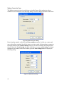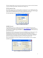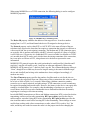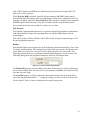
1
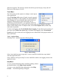
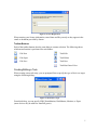
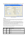
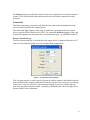
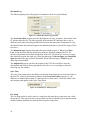
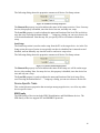
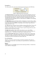
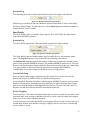
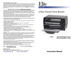
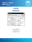
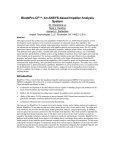
AutoPoll User Manual Part No. 8800‐1177 Version 1.0 October 29, 2008 Sutron Corporation 21300 Ridgetop Circle Sterling, Virginia 20166 TEL: (703) 406‐2800 FAX: (703) 406‐2801 WEB: http://www.sutron.com/ Table of Contents
Introduction................................................................................................................................1
Installation and Startup ..............................................................................................................2
System Requirements............................................................................................................ 2
Installing AutoPoll ................................................................................................................ 2
How to Start the Program ..................................................................................................... 2
Registering the Software....................................................................................................... 2
Uninstalling the Software ..................................................................................................... 3
Using AutoPoll...........................................................................................................................4
Main Window ....................................................................................................................... 4
File Menu .......................................................................................................................... 5
Task Menu ........................................................................................................................ 5
Tools Menu ....................................................................................................................... 6
Help Menu ........................................................................................................................ 6
Toolbar Buttons ................................................................................................................ 7
Creating/Editing a Task ........................................................................................................ 7
Schedule............................................................................................................................ 8
Connection ........................................................................................................................ 9
Action.............................................................................................................................. 13
Device-Specific Tasks ........................................................................................................ 15
SDR Family .................................................................................................................... 15
Monitor ........................................................................................................................... 16
Xpert Family ................................................................................................................... 17
Event Logging..................................................................................................................... 17
Best Practices ...........................................................................................................................19
Configuration Examples ..........................................................................................................20
Monitor via MODBUS Over Cell Modem ......................................................................... 20
Configuring AutoPoll...................................................................................................... 20
Configuring the Monitor ................................................................................................. 22
Configuring the Modem.................................................................................................. 22
Glossary ...................................................................................................................................23
Table of Figures
Figure 1: License Registration .................................................................................................. 2
Figure 2: Main Window............................................................................................................ 4
Figure 3: Options Dialog .......................................................................................................... 6
Figure 4: License Registration .................................................................................................. 7
Figure 5: Select Device Type.................................................................................................... 7
Figure 6: Task Properties .......................................................................................................... 8
Figure 7: Serial Port Properties Dialog..................................................................................... 9
Figure 8: Modem Properties Dialog ....................................................................................... 10
Figure 9: Modem Port Settings ............................................................................................... 10
Figure 10: TCPIP Properties Dialog ....................................................................................... 11
Figure 11: MODBUS Over Direct/Modem Properties ........................................................... 11
iii
Figure 12: MODBUS Over TCPIP Properties........................................................................ 12
Figure 13: Common Send Setup Properties............................................................................ 13
Figure 14: Common Download Log Properties...................................................................... 14
Figure 15: Common Sync Time Properties ............................................................................ 14
Figure 16: Common Get Setup Properties .............................................................................. 15
Figure 17: Common Send Setup Properties............................................................................ 15
Figure 18: SDR Family Download Log Properties................................................................. 16
Figure 19: Monitor Download Log Properties........................................................................ 17
Figure 20: Xpert Download Log Properties............................................................................ 17
iv
INTRODUCTION
AutoPoll is a program for the PC used to perform scheduled remote data collection from
Sutron data loggers. AutoPoll can also transfer setup files and synchronize time. AutoPoll
connects to data loggers through serial and ethernet connections, and supports multiple
protocols, including MODBUS and SCP (Satlink Command Protocol). AutoPoll’s features
are:
•
Remote data collection from Sutron data loggers
•
Downloaded data stored in CSV files
•
Scheduled tasks for unattended operation
•
“Run now” feature for on-demand operation
•
Download logs, synchronize time to PC, get and send setups
•
Direct, phone modem, and IP modem connections
•
MODBUS and SCP protocols
1
INSTALLATION AND STARTUP
This chapter provides information on installing and starting AutoPoll.
System Requirements
The minimum requirements to install AutoPoll are:
•
PC with Microsoft Windows XP, or Windows Vista, operating system
•
Microsoft .NET Framework 3.5
•
Typically 10MB free hard disk space for application files, and as much additional
hard disk space as is requred for storing downloaded CSV files
The AutoPoll installation package may be downloaded from
http://www.sutron.com/downloads/software.htm. Beta versions of AutoPoll (those versions
that are under test and, therefore, not yet released), may be downloaded from
http://www.sutron.com/beta/AutoPoll/AutoPoll.htm.
Installing AutoPoll
To install AutoPoll, download the latest installation package from www.sutron.com, if you
have not already done so, extract the files to a temporary directory, and run the file setup.exe.
This program will verify the correct version of Microsoft .NET Framework is installed. If it
is not, you will be prompted to download and install the correct version.
How to Start the Program
To start AutoPoll, go to Start – All Programs – Sutron – AutoPoll, and click “AutoPoll”.
Registering the Software
AutoPoll will run for 30 days without being registered.
License keys can be purchased from Sutron sales. To enter your license key, select the Help –
License menu item. The following dialog will appear.
Figure 1: License Registration
When entering your license information, enter Name and Key exactly as they appear in the
email or document provided by Sutron.
2
Uninstalling the Software
The software can be uninstalled from the Windows Control Panel applet, “Add/Remove
Programs”.
3
USING AUTOPOLL
This chapter provides information on how to use AutoPoll, addressing such issues as how to
create, configure, and delete tasks, and how to save and load different configurations, or task
sets. Issues specific to a variety of Sutron loggers are also discussed.
Main Window
AutoPoll’s main window displays the list of tasks you have created to perform specific
actions on a schedule. One task appears on each row. Each task represents an action to
perform according to a defined schedule.
Figure 2: Main Window
The Station Name field displays the name you give to the task, which is typically the name
of the target station, but can be anything you deem appropriate.
The Activity field displays the name of the activity the task performs. This can be one of the
following: Download Log, Sync Time, Get Setup, or Send Setup.
The Enabled? field indicates whether the task has been enabled to operate according to it’s
defined schedule. A task is typically left not enabled only when you wish to run the task on
command only, and not automatically according to a schedule. When tasks are paused (by
selecting Tools-Pause All), this field displays “Paused”.
The Last Time field displays the last date and time the task ran, whether that run occurred
according to schedule, or was started manually. Similarly, the Next Time field displays the
date and time the task will next run. The current time is shown in the lower right of the
window, in the status bar, making it easy to determine how long until tasks will run.
The Status field displays the result of the task’s last execution. By default, this field displays
“Ok”, meaning either the last execution ended without error, or the task has not yet run.
When a task execution results in an error, the status field displays a description of the error,
and the task entry is highlighted with red text and a yellow background.
The status bar at the bottom of the window displays a description of the last application
level operation performed (i.e., the name of the last setup file saved, etc.) on the left-hand
side, and displays the current date-time on the right-hand side.
4
File Menu
The File menu is used to create, save, and open setup files, as well
as to exit the application.
Select File-New to create a default setup containing no tasks. The
current setup file, if any is loaded, is closed first. The application
prompts to save, if the current setup has been changed since it was
last saved.
File-Open prompts you to select a setup file to open. The
application prompts to save the current setup, if it has been changed
since it was last saved.
File-Save saves the current setup file. If the current setup file has
not yet been given a name, the application prompts for one. FileSave As prompts for a file name and location to which to save the
current setup file.
Recently used setup files (up to 4) are available selection from the File menu. When one of
these files is selected, it is opened. The application prompts to save the current setup, if it has
been changed since it was last saved.
Select File-Exit to exit the program. If the current setup is not saved, the application prompts
to save before exit.
Task Menu
The Task menu is used to create, delete, and manipulate task entries.
Note that the Task menu can be accessed not only from the program
menu bar, but also as a pop-up menu when right-clicking a task in the
main window.
To edit a task in the list, highlight the task and select Task-Edit (the
option is available only when a task is selected). Any changes you make
to a task take affect only after pressing the edit dialog’s Ok button, and
only after the task is stopped, if it was executing.
To delete a task in the list, highlight the task and select Task-Delete (the option is available
only when a task is selected). If the task is running, it is stopped first, which may take a
while, depending on what type of operation it is currently performing.
To create a new task, select Task-New. You are first prompted for the kind of device you
will target (SDR, Monitor, Xpert, etc.), and then you are provided a dialog used to configure
the task. See the section on creating tasks, later in this document.
To execute a task manually, highlight the task (it must not be currently running), and select
Task-Run. The task will execute, updating Status and Last Time, in the same fashion as a
task that has run according to schedule. To stop a task currently executing, highlight the task
that is currently running, and select Task-Stop. The task will be signaled to stop, which may
take a while, depending on what type of operation it is currently performing. If the task fails
to stop within several seconds, a dialog pops-up to inform you the task may need to be
5
deleted to stop fully. This message assumes the task has got stuck trying to stop, and will
likely never fully stop on it’s own.
Tools Menu
The Tools menu provides options to configure certain aspects
of the application.
Select Tools-Pause All to pause all tasks. Any task currently
running will continue it’s run normally, but will be inhibited
from running at it’s next scheduled time, until all tasks are
unpaused. Pausing tasks is most useful when you are
performing system maintenance, say replacing a modem or
other communications device, and you’d like to ensure tasks do not attempt to run when
failure would certainly result. To unpause tasks, select Tools-Unpause All (available only
when tasks are paused).
To start event logging, select Tools-Enable Event Logging. To open the current event log, if
one exists, select Tools-View Event Log. To Disable event logging, select Tools-Disable
Event Log. See the section on Event Logging for more information of the purpose and use of
these menu items.
Tools – Options Menu
Selecting Tools – Options opens the following dialog.
Figure 3: Options Dialog
Select “Auto load last setup on app start” to cause AutoPoll to load the last setup loaded
when the application starts.
Select “Enable event log on startup” to cause AutoPoll to enable event logging whenever the
application starts.
Help Menu
To view general information about AutoPoll, including a link to
the Sutron website, select Help-About AutoPoll.
To enter or view AutoPoll license information, select HelpLicense…. The following dialog will appear:
6
Figure 4: License Registration
When entering your license information, enter Name and Key exactly as they appear in the
email or document provided by Sutron.
Toolbar Buttons
Each of the toolbar buttons does the same thing as a menu selection. The following shows
which menu function is performed for each button:
File-New
Task-Edit
File-Open
Task-Delete
File-Save
Task-New
Task-Run/Cancel Now
Creating/Editing a Task
When creating a new task entry, you are prompted first to specify the type of device to target
using the following dialog…
Figure 5: Select Device Type
From this dialog, you can specify SDR, WaterMonitor, DitchMaster, Monitor, or Xpert
(more devices may be added as AutoPoll grows).
7
After selecting the type of device to target, the Task Properties Dialog is displayed, which is
used to define the task’s Schedule, Connection, and Action properties.
Figure 6: Task Properties
Schedule
The Schedule group is used to control when and how often a task is executed automatically.
Note that you can run a task at anytime manually by selecting Tools-Run with the task
highlighted in the main window.
The Enable schedule checkbox is used to enable and disable the task. When this box is
checked, the task is automatically executed according to the schedule defined by Time and
Interval. The task may still be run manually at any time by highlighting the task in the task
list and selecting Tools-Run. When the Enable schedule checkbox is not checked, the task
may only be run manually, it will not execute according to schedule.
Time and Interval are used to specify when and how often the task should execute. Time
specifies an offset into the interval. The following shows examples of when a task would
execute based on given Time and Interval values.
Time
Interval
Execution Pattern
00:00:00
01:00:00
… 00:00:00, 01:00:00, 02:00:00, 03:00:00, 04:00:00,
05:00:00…
00:15:00
01:00:00
… 00:15:00, 01:15:00, 02:15:00, 03:15:00, 04:15:00,
05:15:00…
01:00:00
04:00:00
… 01:00:00, 05:00:00, 09:00:00, 13:00:00, 17:00:00,
21:00:00…
8
The Retries property specifies the number of times to try when the task execution results in
an error. This can be useful to help ensure the task succeeds despite connection or other
problems.
Connection
The Connection group is used to specify how the task connects and communicates to the
device in order to perform the assigned action.
The connection Type property offers a list of connection types supported by the current
device, typically Direct, Modem, and TCPIP. The connection Protocol property offers a list
of protocols supported by the current device and connection type, e.g., MODBUS and SCP.
Direct Connection Type
The Direct connection type is used whenever the target device is connected directly to a PC
com port. The following dialog is used to configure Direct connections.
Figure 7: Serial Port Properties Dialog
The Com port property is used to specify the port on which to connect, and displays only the
ports installed on the computer at the time the dialog is opened. Note, however, you can type
in the name of any port you’d like. The remaining settings are used to configure the com
port. Some properties may be disabled. A property is disabled when it does not apply due to
protocol and/or device constraints.
9
Modem Connection Type
The Modem connection type is used whenever AutoPoll must dial a modem in order to
establish a serial connection. The following dialog is used to configure Modem connections.
Figure 8: Modem Properties Dialog
Enter the phone number to dial into the Phone number property. Include any country and
area code prefixes required. Specify the time to wait in seconds for the modem to connect to
the target modem in the Connect timeout property. In order to initialize the modem before
the call, check the Use init string checkbox, and choose, or enter, an Init string. To change
settings used to connect to the local modem, press the Port Settings button to display the
following dialog.
Figure 9: Modem Port Settings
10
The Port Settings dialog is used to specify on which com port to connect to the local modem,
as well as the baud rate and other communication settings to use.
TCPIP Connection Type
The TCPIP connection type is used to connect to a target device over a TCPIP network. The
Xpert2 and 9210B loggers support TCPIP connections directly, whereas other Sutron loggers
can be connected to ethernet to serial converters to enable network access.
The following dialog is used to configure the TCPIP connection type.
Figure 10: TCPIP Properties Dialog
MODBUS Protocol
The MODBUS protocol is a simple and, for the most part, standard serial protocol for
reading and writing registers in a target device. See www.MODBUS.org for more details of
the specification. AutoPoll supports MODBUS over Direct, Modem, and TCPIP (virtual com
port) connection types.
Sutron has developed a simple protocol based on the MODBUS protocol that can be used to
download logs, sync time, and transfer setup files to/from Sutron loggers. Since the
download protocol makes many requests for small amounts of data, where the logger must
search for the start of each request, the download protocol can result in longer download
times than experienced with other protocols (e.g., SCP and Command Line).
When using MODBUS over Direct or Modem, the following dialog is used to configure
MODBUS properties.
Figure 11: MODBUS Over Direct/Modem Properties
11
When using MODBUS over a TCPIP connection, the following dialog is used to configure
MODBUS properties.
Figure 12: MODBUS Over TCPIP Properties
The Device ID property identifies the address of the target device. It can be a number
ranging from 1 to 255, and should match the device ID assigned to the target device.
The Protocol property can be either RTU or ASCII. RTU is the most efficient of the two
selections since it passes the least data, but requires a connection that is nearly as efficient as
a direct serial link, due to strict timing constraints. The Modem and TCPIP connection types
are typically able to perform sufficiently with RTU selected, especially if a Retry of at least 1
is used. However, if in practice it is found that RTU is not as reliable over Modem or TCPIP
as is needed, then ASCII can be used, which relaxes the timing constraints of the connection,
but is not quite as efficient as RTU, using almost twice the data to represent the same
information.
MODBUS RTU protocol requires the serial port/modem be configured for 8 data bits and 2
stop bits (1 stop bit will usually work; 2 stop bits are often not supported). When using
MODBUS ASCII protocol, use 7 data bits, and 1 stop bit. The recommended parity setting is
“None”, though Even or Odd may be used as long the setting is the same in both the target
device and AutoPoll (and as long as the modems have been configured accordingly, if
modems are used).
The Slave Timeout property specifies the number of milliseconds to wait for the slave to
respond, once the request has been sent. When using a Direct connection, this value can often
be as low as 1000 or 2000 (1 or 2 seconds). When using a Modem connection, another
second or two is usually required, and when using a TCPIP connection, several seconds may
be required, depending on network traffic. However, the latency in the device can require this
setting be set much higher. For example, when downloading event data over a period of
several hours, the device may take considerable time to find and load the data for transfer,
requiring an even longer slave timeout setting.
In each MODBUS transaction over Direct and Modem connections, RTS is raised just before
transmitting, and lowered just after transmitting. RTS pre-tx delay specifies the time in
milliseconds to wait after raising RTS before transmitting. RTS post-tx delay specifies the
time in milliseconds to wait before lowering RTS after transmitting. These settings are most
useful when working with a direct connection to a radio, where RTS is used to “key” the
radio, and delays are needed to ensure the radio is in the proper state before changing the
12
state of RTS. Monitor and SDR device families typically need the pre and post RTS TX
delays to be 10ms or greater.
When Wait for DSR is checked, AutoPoll will not transmit a MODBUS packet until it
detects DSR (Data Set Ready), which is an indication from the device connected to the com
port that it is indeed connected. When Wait for CTS is checked, AutoPoll will not transmit a
MODBUS packet until it detects CTS (Clear To Send), which is an indication from the
device connected to the com port that it is ready to receive data.
SCP Protocol
SCP (Satlink Communications Protocol) is a protocol originally developed to communicate
with Sutron Satlink, but has also been adapted for use with the SDR family of Sutron
sensor/loggers.
SCP can be used over Direct, Modem, and TCPIP (virtual com port) connection types. SCP
has no configurable properties.
Action
Each AutoPoll task can be assigned one of the following actions: Download Log, Sync Time,
Get Setup, and Send Setup. The configuration of these tasks are the same, for the most part,
across all devices. However, some devices offer unique properties for each action. The
following sections show how to configure common action properties. See the section, The
following dialog shows the properties common to all device Get Setup actions.
Figure 13: Common Send Setup Properties
The Remote file property is used to indicate the name of the setup as it will be on the target
device, after sending. Note: for many devices, this property is disabled, since the device has
one, and only one, setup.
The Local file property is used to indicate the name and location of the local setup file to
send. Pressing the button labeled “…” brings up a dialog you can use to browse for the file.
Device-Specific Task, for how to configure device-specific properties.
13
Download Log
The following dialog shows the properties common to all device log downloads.
Figure 14: Common Download Log Properties
The Local time offset property specifies the difference in time, in minutes, between the local
PC and the target device. The times typcially differ when the PC and target device are in
difference time zones. Knowing the difference between the time zones is important to a log
download because the download request uses absolute date-times to specify the range of data
to retrieve.
The Download type property determines the span of data to retrieve. When set to Since
Last, all the data since the last download is retrieved. AutoPoll examines the CSV file
directly to determine the last data downloaded. If the CSV file doesn’t yet exist, or is empty,
then AutoPoll requests the entire log. When download type is Recent Span, then Download
span determines the span of data to download. When download type is Whole Log, the
entire log is downloaded.
The Output file property specifies the location of the CSV file in which to store the
downloaded data. Data is always appended to this file, never overwriting or otherwise
removing any file contents.
Sync Time
The Sync Time action causes AutoPoll to set the time in the target device to the same time as
the local PC, offset by the number of minutes in the Local time offset property (i.e., the
difference in minutes between the PC and target device time zones). Local time offset is the
only property that applies to the Sync Time action.
Figure 15: Common Sync Time Properties
Get Setup
The Get Setup action is used to retrieve a setup from the target device, and store it in a local
file on the PC. This type of action is not typically one that is scheduled, but is instead created
disabled, and run manually any time the need to get the setup arises.
14
The following dialog shows the properties common to all device Get Setup actions.
Figure 16: Common Get Setup Properties
The Remote file property is used to indicate the name of the setup to retrieve. Note: for many
devices, this property is disabled, since the device has one, and only one, setup.
The Local file property is used to indicate the name and location of the local file in which to
store the setup. Pressing the button labeled “…” brings up a dialog you can use to browse for
a file location and name. Note that any file you specify will be overwritten with the new
setup.
Send Setup
The Send Setup action is used to send a setup from the PC to the target device. As in the Get
Setup action, this type of action is not typically one that is scheduled, but is instead created
disabled, and run manually any time the need to send a new setup arises.
The following dialog shows the properties common to all device Get Setup actions.
Figure 17: Common Send Setup Properties
The Remote file property is used to indicate the name of the setup as it will be on the target
device, after sending. Note: for many devices, this property is disabled, since the device has
one, and only one, setup.
The Local file property is used to indicate the name and location of the local setup file to
send. Pressing the button labeled “…” brings up a dialog you can use to browse for the file.
Device-Specific Tasks
This section discusses properties that are unique among target devices, as well as any other
device-specific issues.
SDR Family
The SDR family of devices includes SDR, WaterMonitor, and DitchMaster devices. The
SDR family of devices support SCP and MODBUS protocols.
15
Download Log
The following shows the custom log download properties that apply to the SDR family.
Figure 18: SDR Family Download Log Properties
The Download format property determines the format of the downloaded data in the CSV
file. The property can be set to either Group or Flat, where the Group format puts all data
having the same timestamp on the same line, and the Flat format puts data on separate lines.
The Download format property is enabled only when the current Protocol is SCP, since
AutoPoll performs the formatting in this case. When Protocol is MODBUS, Flat formatting
is performed by the device.
The Right Digits property specifies the number of right digits to use for the Stage or Water
Level value in the formatted output. This property is enabled only when the current Protocol
is SCP. When Protocol is MODBUS, the right digits in the formatted output follows the
settings in the device setup.
The SDR family logs event data (Events) in addition to measured data (Data). Events can be
things like Reset, Setup Change, Log Download, etc. The Content property determines
whether to download Data, Events, or Both. Events are separated by pipe characters in the
final field, when Group format is selected.
The Dual sensor property is only available when the device type is either SDR or
DitchMaster, since WaterMonitor does not support dual sensors. Set this according to the
setup in the device, i.e., check the box if dual sensors is enabled in the device.
Check the Separate date, time property to separate date and time into two distinct fields
(separated by comma), as opposed to a single field having a space between date and time.
This option is available only when SCP is the current protocol. When MODBUS is the
current protocol, the device determines the format of date-time.
Get and Send Setup
When the current action is either Get Setup or Send Setup, the Remote file property is
disabled. This is because there is one and only one setup in SDR devices, and the name is
pre-determined.
Monitor
AutoPoll supports using MODBUS protocol when connecting to Monitor. Command Line
will be added in a coming update.
16
Download Log
The following shows the custom log download properties that apply to the Monitor.
Figure 19: Monitor Download Log Properties
Monitor logs event data (Events) in addition to measured data (Data). Events can be things
like Reset, Setup Change, Log Download, etc. The Content property determines whether to
download Data, Events, or Both.
Xpert Family
The Xpert family of devices includes Xpert, Xpert2, 9210, and 9210B. The Xpert family
supports the MODBUS protocol.
Download Log
The Xpert family supports the following custom properties for log downloads.
Figure 20: Xpert Download Log Properties
The Xpert family supports storing multiple log files on the device, each having a unique
name. The Log file property is used to specify from which log to download.
The Request size property specifies the number of data bytes to request be returned in each
packet, when using the MODBUS protocol. The nominal MODBUS packet size is 256 bytes.
However, the Xpert supports larger packets for faster transfers of large data sets. When using
very large packets, be sure to increase the Slave timeout setting in the MODBUS
configuration, since it takes longer for the Xpert to process large packets.
Get and Send Setup
Since the Xpert family supports multiple setup files on the device at any one time, the
Remote file property is enabled for the Get and Send Setup actions.
As mentioned for Download Log above, when using the MODBUS protocol, you can set the
Request size property to determine how many data bytes to request from the Xpert. Larger
packet sizes must be balanced with additional slave timeout. The most efficient values for
Request size and Slave timeout should be determined empirically.
Event Logging
The Event Log is a file where information about task execution is stored. Events such as task
starts and stops, error messages, and other task info is stored, each with a date-time stamp to
make it easy to tell when something occurred.
Use the Tools menu to enable and disable event logging, and to view the current event log, if
one has been defined. Note that the event log is simply a text file, and can be viewed using
any text editor or viewer.
17
Here’s an example of the kind of information that can be captured in an event log…
6/19/2008 5:01:33 PM
6/19/2008 5:01:38 PM
6/19/2008 5:01:38 PM
166.161.217.254:3001
6/19/2008 5:01:47 PM
6/19/2008 5:02:35 PM
6/19/2008 5:02:53 PM
166.161.217.254:3001
6/19/2008 5:02:55 PM
None.
6/19/2008 5:12:05 PM
18
- Started event logging.
- SDRTask executing...
- SerialPortIP: Socket connected to
- Ending successful download attempt.
- SDRTask executing...
- SerialPortIP: Socket connected to
- Ending FAILED download attempt. Status...
- Stopping event logging.
BEST PRACTICES
Here are some guidelines to keep in mind when setting up your system:
•
Schedule downloads to start when the system is idle (well in between measurements).
The “since last” algorithm relies on the last value stored, which means if the log contains
data after the last value retrieved, but with the same time stamp, it will be missed.
•
The fastest download times are achieved typically when using protocols the SCP or
Command Line protocols. Downloads using MODBUS can be the slowest since each
request must be treated as as new search for data.
•
Add AutoPoll to the Startup Group of the PC on which it runs, and check the “Auto load
last setup on app start” option under Tools – Options. Doing these two steps will ensure
AutoPoll automatically starts and runs your tasks, if the PC reboots.
19
CONFIGURATION EXAMPLES
This section describes how to configure the communications equipment in several AutoPoll
deployment scenarios.
Monitor via MODBUS Over Cell Modem
In this example, MODBUS is used to retrieve log data from a Radar connected to a Multitech
GPRS cellular modem.
Configuring AutoPoll
This section explains how to configure communication settings in AutoPoll to support the
example scenario.
Modem Properties
The dialog below shows how we want to configure modem properties in AutoPoll.
When defining modem properties, enter the phone number to call into the Phone number
field. Also enter a timeout (the default of 60 seconds should be enough; enter more if the
modem takes a long time to answer).
Uncheck the “Use init string” checkbox. This tells AutoPoll not to configure the modem.
We’ll configure the modem manually up front ourselves, and write that configuration to the
modem’s memory, so that it is restored automatically anytime the modem reboots.
Serial Port Properties
The dialog below shows how we want to configure the serial port properties in AutoPoll.
These properties define the data stream we provide to the modem attached to the PC (or the
20
modem inside the PC, as the case may be). Our goal is to define the settings the way the
Monitor expects.
The Com port field should be set to the com port that is attached to the PC modem. Even
internal modems are assigned a com port number. This number can usually be determined by
looking at the properties of the modem in the Windows Control Panel.
The ideal baud rate is the one that is as close as possible to the modem’s actual throughput.
Generally speaking, 9600 is a good choice. Since the MODBUS RTU protocol requires strict
timing, it is best to err on the low side, as 9600 baud does (the actual throughput is likely
higher).
In this example, we use a Parity setting of None. This is the recommended setting whenever
MODBUS is used. Since MODBUS transactions are always validated using a CRC check,
parity offers no help in error detection. In addition, many modems do not appear to support
the not often used 8E1 data format characteristics that MODBUS RTU with Even parity
require.
Modbus Master Properties
The dialog below shows how we want to configure the MODBUS properties in AutoPoll.
The Device ID field is set the the same Device ID value set in the Monitor.
21
The Protocol field is set to RTU. The RTU protocol is the most efficient of the two available
(the other is ASCII). RTU requires the communications line to be almost as efficient as a
direct serial link. Since MODBUS packets are typically fairly small, it’s not usually a
problem to use RTU with modems, as in our case.
In this example, we set the Slave timeout field to 5 seconds. This means AutoPoll expects to
receive a response from Monitor within 5 seconds. If no response is seen, AutoPoll will retry
as many times as have been defined in the Retries field (in the Schedule group on the
Monitor Task Properties dialog).
Configuring the Monitor
Configure the Monitor using it’s front panel interface, as follows.
Access the MODBUS setup menu under Station Setup – Modbus Settings.
Set Modbus Enable to Enabled.
Set Modbus Device ID to 1.
Set Modbus Protocol to RTU.
Set Modbus Parity to None.
Set Delay Before Tx to 10ms.
Set Delay After Tx to 10ms.
Set Modbus BaudRate to 9600.
Configuring the Modem
The Multitech modem in this example must be configured so that it communicates properly
with the Monitor. To configure the modem, connect the modem to a com port on your PC,
and start a Hyperterm session on the same com port. When starting the Hyperterm session,
use com port settings of 9600 baud, 8 data bits, no parity, and 1 stopbit. To determine if the
settings are sufficient, type
at&v
The modem should respond with something that looks like the following:
Q:1 V:1 S0:001 S2:043 S3:013 S4:010 S5:008
+CR:0 +CRC:0 +CMEE:0 +CBST:0,0,1
+SPEAKER:0 +ECHO:0,1 &C:1 &D:2 %C:0
+IPR:9600 +ICF:3,4 +IFC:0,0
If you don’t see anything, then the Hyperterm settings are not correct. Experiment with other
values, including 115200 baud. Once you have established communication, enter the
following commnds:
at+ifc=0,0
ats0=1
atq1
at+ipr=9600
at+icf=3,4
at&w
Disable flow control
Answer on 1 ring
Turn off result codes
9600 baud
8N1
Save configuration to memory
The modem is now configured for use with the Monitor and Autopoll using MODBUS over
the Multitech GPRS cell modem.
22
GLOSSARY
CSV File – A CSV (Comma Separated Values) file is an ASCII text file containing
downloaded data formatted such that each field within a row is separated by a comma. The
arrangement of fields within each row is typically determined by the logger. Some formatting
within each field (right digits, etc.) can be controlled by task settings.
Event Log – A text file containing time-stamped AutoPoll event information, i.e., indications
of tasks starts, task stops, error conditions, etc.
Flat Format – An output format for downloaded log data where each line of the output
contains a single, time-stamped data or event item.
Group Format – An output format for downloaded log data where each line of the output
contains all data having the same time-stamp (to the second).
MODBUS – A standard communications protocol supported by several Sutron loggers. See
www.MODBUS.org for more information.
Command Line – A general reference to any communication protocol where the user types
commands and receives ASCII text responses from the logger.
Monitor – A Sutron logger intended for low-cost applications.
Satlink – A Sutron satellite transmitter and low-cost logger, combined.
SCP (Satlink Command Protocol) – A communications protocol supported by the Sutron
Satlink and SDR logger families.
SDR (Stage Discharge Recorder) – A Sutron logger intended for measuring and recording
stage using a shaft encoder or analog input.
Setup File – The file used to store an AutoPoll configuration. Each setup file contains a
definition of a task set.
Task – The fundamental object created and managed by AutoPoll that determines what
action to perform, and how and when to perform it. Each row in the AutoPoll main window
represents a task.
Task Set – A set of tasks stored in a configuration, or setup file.
Xpert – A Sutron logger family consisting of Xpert, Xpert2, 9210, and 9210B. These loggers
support a variety of input types (analog, digital, SDI, etc.), very large logs, expanded
communications (modem, radio, satellite, etc.), and lots of processing power. The Xpert and
Xpert2 loggers provide a quarter panel LCD graphical display for configuration and data
display.
23