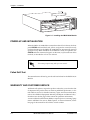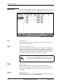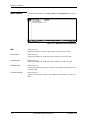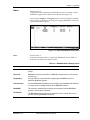
1
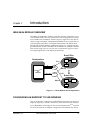
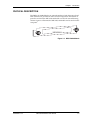
IMUX-56/64 Module
User Manual
Part Number 1200262L1
61200262L1-1A
July 1999
901 Explorer Boulevard
P.O. Box 140000
Huntsville, AL 35814-4000
(256) 963-8000
© 1999 ADTRAN, Inc.
All Rights Reserved.
Printed in U.S.A.
ADTRAN Year 2000 (Y2K) Readiness Disclosure
ADTRAN has established a Year 2000 program to ensure that our products will correctly function in
the new millennium. ADTRAN warrants that all products meet Year 2000 specifications regardless of
model or revision. Information about ADTRAN's Year 2000 compliance program is available at the following:
Product Matrix
www.adtran.com/y2kfax.html
E-mail
[email protected]
Faxback Document Line
(256) 963-8200
Y2K plans and product certifications are listed in the Product Matrix (see above).
Y2K Project Line
(256) 963-2200
Federal Communications Commission Radio Frequency Interference Statement:
This equipment has been tested and found to comply with the limits for a Class A digital device, pursuant to Part 15 of the FCC Rules. These limits are designed to provide reasonable protection against
harmful interference when the equipment is operated in a commercial environment. This equipment
generates, uses, and can radiate radio frequency energy and, if not installed and used in accordance
with the instruction manual, may cause harmful interference to radio frequencies. Operation of the is
equipment in a residential area is likely to cause harmful interference in which case the user will be
required to correct the interference at his own expense.
Changes or modifications to this unit not expressly approved by the party responsible
for compliance could void the user’s authority to operate the equipment.
iii
iv
Table of Contents
List of Figures ....................................................................................................................................................vii
List of Tables....................................................................................................................................................... ix
Chapter 1. Introduction.................................................................................................................................. 1-1
IMUX-56/64 Module Overview .................................................................................................................... 1-1
Configuring an Endpoint to use BONDING ................................................................................................ 1-1
Functional Description .................................................................................................................................... 1-2
Features ....................................................................................................................................................... 1-2
Physical Description ........................................................................................................................................ 1-3
Chapter 2. Installation.................................................................................................................................... 2-1
Unpack and Inspect ......................................................................................................................................... 2-1
Contents of ADTRAN Shipment ............................................................................................................. 2-1
Installing The IMUX-56/64 Module ............................................................................................................. 2-1
Power-Up and Initialization ........................................................................................................................... 2-2
Failed Self-Test ........................................................................................................................................... 2-2
Warranty and Customer Service .................................................................................................................... 2-2
Chapter 3. Operation ...................................................................................................................................... 3-1
Overview ........................................................................................................................................................... 3-1
Terminal Menu Structure ............................................................................................................................... 3-1
Menu Access ..................................................................................................................................................... 3-2
System Config ................................................................................................................................................... 3-2
BONDING Config .................................................................................................................................... 3-2
TXINIT Timer ..................................................................................................................................... 3-2
TXFA Timer ........................................................................................................................................ 3-2
TXADD01 Timer ................................................................................................................................ 3-3
TXDEQ Timer ..................................................................................................................................... 3-3
TANULL Timer .................................................................................................................................. 3-3
TCID Timer ......................................................................................................................................... 3-3
Call Stagger ......................................................................................................................................... 3-3
Modules ............................................................................................................................................................. 3-4
Slt ................................................................................................................................................................. 3-4
Type ............................................................................................................................................................ 3-4
Menu ........................................................................................................................................................... 3-4
Alarm .......................................................................................................................................................... 3-4
State ............................................................................................................................................................. 3-5
Status .......................................................................................................................................................... 3-5
Rev .............................................................................................................................................................. 3-5
IMUX Menu ...................................................................................................................................................... 3-6
Info .............................................................................................................................................................. 3-6
61200262L1-1A
IMUX-56/64 Module User Manual
v
Table of Contents
Part Number ....................................................................................................................................... 3-6
Serial Number .................................................................................................................................... 3-6
Board Revision ................................................................................................................................... 3-6
Firmware Revision ............................................................................................................................. 3-6
Status ........................................................................................................................................................... 3-7
Status ................................................................................................................................................... 3-7
NumBChannels .................................................................................................................................. 3-8
Data Rate ............................................................................................................................................. 3-8
Bonded Ep ........................................................................................................................................... 3-8
Configuration ............................................................................................................................................ 3-8
ATLAS Features used with IMUX-56/64 Module Options ....................................................................... 3-8
Factory Restore ........................................................................................................................................... 3-9
System Self-Test ......................................................................................................................................... 3-9
Index ...........................................................................................................................................................Index-1
vi
IMUX-56/64 Module User Manual
61200262L1-1A
List of Figures
Figure 1-1. ATLAS Remote Access Application ........................................................................................ 1-1
Figure 1-2. Interface Configuration Example ............................................................................................. 1-2
Figure 1-3. IMUX-56/64 Module ................................................................................................................. 1-3
Figure 2-1. Installing the IMUX-56/64 Module ......................................................................................... 2-2
Figure 3-1. BONDING Config Submenu .................................................................................................... 3-2
Figure 3-2. Modules Menu ............................................................................................................................ 3-4
Figure 3-3. IMUX-56/64 Module Submenus .............................................................................................. 3-6
Figure 3-4. IMUX-56/64 Module Status Menu .......................................................................................... 3-7
Figure 3-5. IMUX-56/64 Module Config Menu ......................................................................................... 3-8
61200262L1-1A
IMUX-56/64 Module User Manual
vii
List of Figures
viii
IMUX-56/64 Module User Manual
61200262L1-1A
List of Tables
Table 3-1. Management Methods for the IMUX-56/64 Module ................................................................ 3-1
Table 3-2. Call Stagger Values......................................................................................................................... 3-3
Table 3-3. Status Messages............................................................................................................................... 3-5
Table 3-4. BONDING Status Display Values ................................................................................................ 3-7
61200262L1-1A
IMUX-56/64 Module User Manual
ix
List of Tables
x
IMUX-56/64 Module User Manual
61200262L1-1A
Chapter 1
Introduction
IMUX-56/64 MODULE OVERVIEW
The IMUX-56/64 Module combines with other ATLAS components to provide a flexible disaster recovery system in the ATLAS Integrated Access System. The IMUX-56/64 Module, which occupies a single slot in the ATLAS
chassis, supports multiple, independent BONDING sessions with each session having the potential to use a different bandwidth. The IMUX-56/64
Module can use either 56Kbps or 64Kbps data lines (i.e., channels) for any
given BONDING session. The IMUX-56/64 Module can establish a BONDING session using as few as 2 or as many as 32 channels. Figure 1-1 shows
an example application of the IMUX-56/64 Module.
Branch Office
Headquarters
TSU IQ
T1/fT1
T1
ATLAS 810PLUS
with
IMUX-56/64
BRI or PRI
Router
DBU
ISU 612
Frame
Relay
PSTN
BRI (x4)
T1/fT1
BRI (x4)
Branch Office
TSU IQ
Router
DBU
ISU 612
Figure 1-1. ATLAS Remote Access Application
CONFIGURING AN ENDPOINT TO USE BONDING
How an endpoint is configured to use BONDING is unique to each type of
endpoint. Typically, it will be a reference to the number of DS0s, with mention of BONDING in the help line. See the ATLAS 800 or 800 PLUS manuals
for more information on endpoint configuration. Information may also be
61200262L1-1A
IMUX-56/64 Module User Manual
1-1
Chapter 1. Introduction
found in the help menus under the endpoint’s Dial plan Interface configuration.
For example, to configure an Nx endpoint for BONDING, set Max DS0s and
Min DS0s to something other than 1 under the Nx Dial Plan interface configuration (see Figure 1-2).
Figure 1-2. Interface Configuration Example
FUNCTIONAL DESCRIPTION
The IMUX-56/64 Module installs into any available slot in the ATLAS chassis. The status of the module itself can be viewed from the ATLAS front panel. Additional status information is available via the terminal menu,
accessible through either a VT-100 terminal connected to the ATLAS Base
Unit’s control port or via a Telnet session established through the Base Unit’s
Ethernet port. The IMUX-56/64 Module can be configured and application
software can be downloaded using the terminal menu.
Features
•
•
1-2
Compliant with TIA/EIA-619 Standard (BONDING)
-
Up to (32) 128Kbps BONDING sessions per module
-
Up to (8) 512Kbps BONDING sessions per module
-
Up to (2) 2.048Mbps BONDING sessions per module
Event-driven dial-backup of frame relay or T1 circuits
•
Support for 56K or 64K circuits
•
Video Conferencing
•
Software upgrades via FLASH download
IMUX-56/64 Module User Manual
61200262L1-1A
Chapter 1. Introduction
PHYSICAL DESCRIPTION
The IMUX-56/64 Module has no external interfaces. Both the network and
DTE interfaces are provided on other ATLAS components. Information is
passed to and from the IMUX-56/64 Module via ATLAS’ internal bussing
scheme. Figure 1-3 illustrates the IMUX-56/64 Module card as seen from the
rear panel.
IMUX-56/64
Figure 1-3. IMUX-56/64 Module
61200262L1-1A
IMUX-56/64 Module User Manual
1-3
Chapter 1. Introduction
1-4
IMUX-56/64 Module User Manual
61200262L1-1A
Chapter 2
Installation
UNPACK AND INSPECT
Carefully inspect the IMUX-56/64 Module for shipping damages. If damage
is suspected, file a claim immediately with the carrier and then contact
ADTRAN Technical Support. If possible, keep the original shipping
container for use in returning the IMUX-56/64 Module for repair or for
verification of shipping damage.
Contents of ADTRAN Shipment
The following items are included in the ADTRAN shipment:
•
IMUX-56/64 Module
•
IMUX-56/64 Module User Manual (insert into main ATLAS User Manual)
INSTALLING THE IMUX-56/64 MODULE
The installation procedure is described below, and Figure 2-1 shows the
proper placement of the option module.
Instructions for Installing the IMUX-56/64 Module
61200262L1-1A
Step
Action
1
Remove the cover plate (corresponding to the slot into which the
IMUX-56/64 Module will be installed) from the ATLAS chassis
rear panel.
2
Slide the IMUX-56/64 Module into the ATLAS chassis until the
module is positioned firmly against the front of the ATLAS unit.
3
Fasten the thumbscrews at both edges of the option module.
4
Complete installation of remaining modules and Base Unit as
specified in the Installation chapter of the ATLAS User Manual.
IMUX-56/64 Module User Manual
2-1
Chapter 2. Installation
IMUX-56/64
Figure 2-1. Installing the IMUX-56/64 Module
POWER-UP AND INITIALIZATION
When the IMUX-56/64 Module is inserted into the ATLAS chassis, the front
panel STATUS indicator blinks red, yellow, and green for a time. Previously
configured settings for the IMUX-56/64 Module are automatically restored
upon power-up. When the IMUX-56/64 Module is ready for operation, the
STATUS indicator remains solid green. At this time, a system self-test can be
invoked, as described in ATLAS User Manual.
This startup sequence may take up to ten seconds.
Failed Self-Test
The terminal menu self-test log records self-test failures for the IMUX-56/64
Module.
WARRANTY AND CUSTOMER SERVICE
ADTRAN will replace or repair this product within five years from the date
of shipment if the product does not meet its published specification, or if it
fails while in service. For detailed warranty, repair, and return information,
refer to the ADTRAN Equipment Warranty and Repair and Return Policy
Procedure (see the last page of this manual for pertinent information).
A return material authorization (RMA) is required prior to returning equipment to ADTRAN. For service, RMA requests, or more information, see the
last page of this manual for the toll-free contact number.
2-2
IMUX-56/64 Module User Manual
61200262L1-1A
Chapter 3
Operation
OVERVIEW
You can configure and control the IMUX-56/64 Module from several sources, as shown in Table 3-1. The ATLAS User Manual provides detailed instructions on operating each of the supported management approaches. The
remainder of this chapter describes the menu items available for managing
the IMUX-56/64 Module using the terminal menu.
Table 3-1. Management Methods for the IMUX-56/64 Module
Source
Purpose
ATLAS Front Panel
For minimal configuration and status support
Terminal Menu
For detailed configuration, status, and
diagnostics
Simple Network
Management Protocol
(SNMP)
For reporting alarm conditions and system
status (no configuration)
You must have the appropriate password level to edit items using
the terminal menu. (See the section Access Passwords in the
ATLAS User Manual for detailed information on working with
passwords.)
Security level 1 users can view and edit every available field.
Security level 5 users can view any field, but they cannot edit.
Each menu description in this section indicates the required
password level required for write and read access.
TERMINAL MENU STRUCTURE
ATLAS uses hierarchical menus to access all of its features. The top-most
menu level leads to submenus which are grouped by functionality. All submenu options display in the VT-100 terminal window.
You can use the Modules terminal menu to configure and control the
IMUX-56/64 Module. The Modules menu option, Type, shows the IMUX-56/
64 Module as IMUX (see Figure 3-2). The following sections describe the Modules menu and its submenus.
61200262L1-1A
IMUX-56/64 Module User Manual
3-1
Chapter 3. Operation
MENU ACCESS
The ATLAS System Controller automatically detects the presence of the
IMUX-56/64 Module when it is installed in the system. To access menus and
submenus, use the keyboard arrow keys to scroll to the appropriate row and
column; then press Enter on the keyboard.
For example, to view the Menus submenu for IMUX, use the keyboard arrow
keys to move to the row IMUX and the column Menu; then press Enter on
the keyboard.
Refer to the ATLAS User Manual for detailed instructions on
how to navigate through the terminal menu.
SYSTEM
CONFIG
The IMUX-56/64 Module includes a BONDING Config submenu under the
System Config menu. The following paragraphs describe this submenu.
BONDING Config
Write security: 5; Read security: 5
Displays the configuration submenus available for the IMUX-56/64 Modules. This configuration is shared among all IMUX-56/64 Modules (see Figure 3-1).
Figure 3-1. BONDING Config Submenu
TXINIT Timer
Write security: 3; Read security: 5
Specifies the length of time the originating endpoint attempts to detect the
BONDING negotiation pattern from the answering endpoint before deciding the BONDING call has failed.
TXFA Timer
Write security: 3; Read security: 5
Specifies the length of time both endpoints attempt to detect the BONDING
frame pattern when a call is connected before deciding the BONDING call
has failed. When interoperating with other manufacturers' BONDING
3-2
IMUX-56/64 Module User Manual
61200262L1-1A
Chapter 3. Operation
equipment, it may be necessary to change this time so that it matches
TXADD01.
TXADD01 Timer
Write security: 3; Read security: 5
Specifies the length of time both endpoints wait for additional calls to be
connected at the end of negotiation before deciding that the BONDING call
has failed. The factory default setting is sufficient for most calls to connect,
although when dialing overseas it may be necessary to lengthen this timer
to allow for slower call routing.
TXDEQ Timer
Write security: 3; Read security: 5
Specifies the length of time both endpoints attempt to equalize the network
delay between the bearer channels before deciding the BONDING call has
failed.
TANULL Timer
Write security: 3; Read security: 5
Specifies the length of time the answering endpoint attempts to detect the
BONDING negotiation pattern from the originating endpoint before deciding the BONDING call has failed. It may be necessary to shorten this timer
if the DTE equipment using the BONDING module also has timer constraints for completing non-BONDING parameter negotiation.
TCID Timer
Write security: 3; Read security: 5
Specifies the length of time both endpoints attempt to negotiate an agreeable value for bearer channels and channel capacities before deciding the
BONDING call has failed.
Call Stagger
Write security: 3; Read security: 5
Specifies the amount of delay between placing calls for outgoing BONDING sessions. Table 3-2 defines the call stagger values.
Table 3-2. Call Stagger Values
Display value
Meaning
No Stagger
There is no delay between the call dialing of a BONDING session.
500 ms
Wait approximately ½ second between the call dialing of a BONDING session.
1 sec
Wait approximately 1 second between the call dialing of a BONDING session.
2 sec
Wait approximately 2 seconds between the call dialing of a BONDING session.
61200262L1-1A
IMUX-56/64 Module User Manual
3-3
Chapter 3. Operation
MODULES
The following paragraphs (Slt (slot), Type, Menu, Alarm, State, Status, and
Rev (revision)) describe the IMUX-56/64 Modules fields (see Figure 3-2).
Figure 3-2. Modules Menu
Slt
Read security: 5
(Slot) Displays the number of available slots in the ATLAS chassis. Slot 0
refers to the ATLAS Base Unit.
Type
Write security: 3; Read security: 5
Displays the module type currently installed in the slot or the module type
you plan to install in the slot. If an IMUX-56/64 Module is installed, the
Type field automatically defaults to IMUX (the IMUX-56/64 Module). You
can use this field to preconfigure the system before installing modules by
specifying the module that you want to install into each slot.
If a module is installed, Type automatically displays the name of
the installed module, and it cannot be set to any other option.
Menu
Read security: 5
Displays additional status and configuration submenus for the
IMUX-56/64 Module. (To access the submenus for this item, use the arrow
keys to scroll to the Menu column for the module you want to edit, and
press Enter.)
Alarm
Read security: 5
Displays whether there is an alarm condition on the IMUX-56/64 Module.
Press Enter in this field to activate the Alarm menu.
3-4
IMUX-56/64 Module User Manual
61200262L1-1A
Chapter 3. Operation
State
Read security: 5
Displays whether the module is online or offline. Even though a module is
physically installed, it must be marked Online for it to be considered an
available resource. Marking an installed module Offline may be useful in
system troubleshooting. If you choose Offline, the module will not be in
alarm condition, but will display Offline.
Only if State reads Online, can the ATLAS use an installed
module for any data bandwidth.
Status
Read security: 5
Displays status information on the IMUX-56/64 Module. Table 3-3
describes status messages that may appear and their meanings.
Rev
Read security: 5
(Hardware Revision) Displays the hardware revision of the IMUX-56/64
Module.
Table 3-3. Status Messages
Message
Meaning
Comments
Online
The module is enabled and is responding to the
system controller’s status polls.
This is the normal response of
the system.
No Response
The module is enabled but is not responding to the
system controller’s status polls.
This response indicates either a
problem in the system or the
module is not installed.
Empty
The system controller has not detected the
presence of a module in the option slot, nor has a
module been manually enabled for this option slot.
Offline
The module is installed but has been taken Offline
by a user.
The module is still responding to
controller polls.
Offline /
No Response
The module is installed but has been taken Offline
by a user. The module is not responding to polls.
This response indicates either a
problem in the system or the
module is not installed.
Not Ready
The module is installed and performing startup
initialization.
The initialization of the IMUX56/64 should take less than 10
seconds.
61200262L1-1A
IMUX-56/64 Module User Manual
3-5
Chapter 3. Operation
IMUX MENU
The IMUX Menu fields include Info, Status, and Configuration (see Figure 33).
Figure 3-3. IMUX-56/64 Module Submenus
Info
Read security: 5
Displays module and software information for the option module.
Part Number
Read security: 5
Displays the IMUX-56/64 Module part number in a read-only field.
Serial Number
Read security: 5
Displays the IMUX-56/64 Module serial number in a read-only field.
Board Revision
Read security: 5
Displays the printed circuit board revision of the IMUX-56/64 Module in a
read-only field.
Firmware Revision
Read security: 5
Displays the firmware revision of the IMUX-56/64 Module in a read-only
field.
3-6
IMUX-56/64 Module User Manual
61200262L1-1A
Chapter 3. Operation
Status
Read security: 5
Displays the Status submenus for BONDING resources available on both
BONDING engines on the IMUX-56/64 Module (see Figure 3-4).
The list entries Engine 1 and Engine 2 in the status list display the BONDING resources available for incoming and outgoing BONDING calls on the
separate BONDING engines.
Figure 3-4. IMUX-56/64 Module Status Menu
Status
Read security: 5
Indicates the current status of a particular BONDING session. Table 3-4
defines the possible status display values.
Table 3-4. BONDING Status Display Values
Display Value
Meaning
Idle
Indicates the number of Idle BONDING resources for a particular BONDING
engine.
Reserved
BONDING resources reserved for a BONDING session that is in the process
of coming up.
Negotiating
A single channel is connected and negotiating the BONDING call for a
particular BONDING session.
Add Channels
The initial BONDING negotiation was successful, and the IMUX-56/64 Module
is in the process of adding channels to the BONDING session.
BONDING
The remaining channels were brought up successfully, and the BONDING
session is now ready to pass data.
Terminated
The BONDING session has been terminated for some reason and is in the
process of freeing BONDING resources.
61200262L1-1A
IMUX-56/64 Module User Manual
3-7
Chapter 3. Operation
NumBChannels
Read security: 5
Displays the number of bearer channels used in this BONDING session.
When the number is displayed in the format X/Y, Y is the number of
BONDING resources reserved for this session, and X is the number of calls
belonging to this session that are up. If just a number is displayed, then all
calls are up, and the number displayed is the number of BONDING
resources in use for this session.
Data Rate
Read security: 5
Displays the data rate for this BONDING session. The number in the parenthesis is the data rate of the individual bearer channels.
Bonded Ep
Read security: 5
Displays the slot and port of the terminating endpoint that is using this
BONDING session.
Configuration
Read security: 5
Displays the configuration submenus available for the IMUX-56/64 Module (see Figure 3-5).
Changes to the configuration of any IMUX-56/64 Module will be
propagated to all IMUX-56/64 Modules.
Figure 3-5. IMUX-56/64 Module Config Menu
For a description of the individual timers, see BONDING Config on page 3-2.
ATLAS FEATURES USED WITH IMUX-56/64 MODULE OPTIONS
In addition to the IMUX-56/64 Module menu items, two additional ATLAS
menu items may be operated in conjunction with the IMUX-56/64 Module.
These are Factory Restore and System Self-test.
3-8
IMUX-56/64 Module User Manual
61200262L1-1A
Chapter 3. Operation
Factory Restore
Individual IMUX-56/64 Modules do not have independent configurations;
there is one configuration for all IMUX-56/64 Modules in an ATLAS. This
configuration can be returned to factory default by pressing F while the cursor is positioned over the BONDING Config submenu, found in the System
Config menu.
Factory defaulting an individual IMUX-56/64 Module will not affect the
configuration.
System Self-Test
System Self-test, a submenu of the ATLAS main menu item System Utility,
executes both the IMUX-56/64 Module internal test and the ATLAS internal
test. The results of the self-test are displayed in the self-test log.
The unit continuously updates the display on the self-test log screen until all
test results are shown. For additional information on self-test, see the ATLAS
User Manual.
61200262L1-1A
IMUX-56/64 Module User Manual
3-9
Chapter 3. Operation
3-10
IMUX-56/64 Module User Manual
61200262L1-1A
Index
A
accessing menus 3-2
ALARM 3-4
ATLAS features 3-8
ATLAS system controller 3-2
structure 3-1
modem
description 1-1, 1-3
features 1-2
MODULES 3-4
B
N
BOARD REVISION 3-6
BONDED EP 3-8
BONDING CONFIG 3-2
BONDING status display values 3-7
NUMBCHANNELS 3-8
O
offline state 3-5
online state 3-5
C
P
CALL STAGGER 3-3
call stagger values 3-3
configuring Modem-16 Module 3-1
PART NUMBER 3-6
password levels 3-1
D
R
DATA RATE 3-8
repair 2-2
return information 2-2
REV 3-5
RMA requests 2-2
F
factory restore 3-8
failed self-test 2-2
FCC statement iii
FIRMWARE REVISION 3-6
H
hardware revision 3-5
I
S
self-test, system 3-9
SERIAL NUMBER 3-6
service 2-2
shipping
contents 2-1
damage 2-1
IMUX MENU 3-6
INFO 3-6
initialization 2-2
installing the modem 2-1
items included in shipment 2-1
M
MENU 3-4
menu
61200262L1
IMUX-56/64 Module User Manual
Index-1
Index
SLT 3-4
STATE 3-5
STATUS 3-5, 3-7
status messages for Modem-16 3-5
SYSTEM CONFIG 3-2
system self-test 3-8, 3-9
T
TANULL TIMER 3-3
TCID TIMER 3-3
terminal menu
navigating 3-2
terminal menu structure 3-1
tests
power up 2-2
Index-2
self-test, failed 2-2
system self-test 3-8
TXADD01 TIMER 3-3
TXDEQ TIMER 3-3
TXFA TIMER 3-2
TXINIT TIMER 3-2
TYPE 3-4
type menu 3-4
W
warranty 2-2
Y
Y2K iii
IMUX-56/64 Module User Manual
61200262L1
Product Support Information
Presales Inquiries and Applications Support
Please contact your local distributor, ADTRAN Applications Engineering, or ADTRAN Sales:
Applications Engineering
(800) 615-1176
Sales
(800) 827-0807
Post-Sales Support
Please contact your local distributor first. If your local distributor cannot help, please contact ADTRAN Technical Support and have the unit serial number available.
Technical Support
(888) 4ADTRAN
Repair and Return
If ADTRAN Technical Support determines that a repair is needed, Technical Support will coordinate
with the Customer and Product Service (CAPS) department to issue an RMA number. For information
regarding equipment currently in house or possible fees associated with repair, contact CAPS directly
at the following number:
CAPS Department
(256) 963-8722
Identify the RMA number clearly on the package (below address), and return to the following address:
ADTRAN Customer and Product Service
6767 Old Madison Pike
Progress Center
Building #6 Suite 690
Huntsville, Alabama 35807
RMA # _____________