1
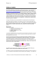
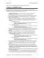
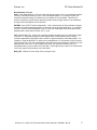
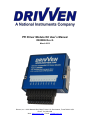
PFI Driver Module Kit User’s Manual D000006 Rev G March 2012 Drivven ,Inc. • 12001 Network Blvd, Bldg E, Suite 110 • San Antonio, Texas 78249 • USA Phone : 210.248.9308 Web : www.drivven.com , E-mail : [email protected] Drivven, Inc. PFI Driver Module Kit Contents Introduction ......................................................................................................................... 3 Pinout .................................................................................................................................. 4 Hardware ............................................................................................................................. 4 Powering the Module .......................................................................................................... 5 Platform Compatibility ....................................................................................................... 6 Port Fuel Injector Drivers ................................................................................................... 8 Low-Side Drivers .............................................................................................................. 12 Software Installer .............................................................................................................. 14 Creating a LabVIEW Project ............................................................................................ 15 Sub VI Documentation ..................................................................................................... 18 Fuel Command Scheduling Notes .................................................................................... 26 Warning About FPGA I/O Node Wiring .......................................................................... 27 Compliance and Certifications .......................................................................................... 28 Physical Specifications and Characteristics ...................................................................... 29 © Drivven, Inc. 2009 • PFI Driver Module Kit User’s Manual • D000006 • Rev G 2 Drivven, Inc. PFI Driver Module Kit Introduction The Port Fuel Injector Driver Module Kit provides a CompactRIO (cRIO) module for driving low and high impedance Port Fuel Injectors (PFI) and general purpose automotive solenoid valves. The kit includes a LabVIEW FPGA VI for controlling each driver channel. Each PFI driver is individually controlled for timing and duration. Each general purpose low-side solenoid driver is PWM controlled, capable of 0-100% duty cycle operation. Features: 4-channel low or high impedance PFI driver o Peak/hold current control for low impedance injectors o 4-amp peak / 1-amp hold current profile (standard configuration) o Tunable peak duration o Open/short circuit detection and reporting with short circuit disable 4-channel general purpose low-side solenoid driver o 1.2-amp continuous duty o PWM controlled 0-100% duty cycle operation 2 Hz – 10 kHz frequency operation 500 nanosecond resolution o Open/short circuit detection and reporting with short circuit disable External power supply of 6-32V © Drivven, Inc. 2009 • PFI Driver Module Kit User’s Manual • D000006 • Rev G 3 Drivven, Inc. PFI Driver Module Kit Pinout Hardware The PFI Driver Module Kit provides four port fuel injector drivers and four general purpose lowside solenoid drivers in a National Instruments CompactRIO module. © Drivven, Inc. 2009 • PFI Driver Module Kit User’s Manual • D000006 • Rev G 4 Drivven, Inc. PFI Driver Module Kit Powering the Module The PFI Driver module requires power from two different sources. One source is from the CompactRIO backplane male high density D-Sub 15-pin (HD15) connector which mates with the module’s female HD15 connector. This power source provides a regulated 5 volts and ground to various digital logic functions within the module. The CompactRIO 5V source is active whenever the CompactRIO or R-Series Expansion Chassis is properly powered. The module should only be powered at the HD15 connector by plugging it into a CompactRIO or R-Series Expansion Chassis. The module’s HD15 connector should not be connected to any other device. Another required power connection is at the external screw terminal connector. The terminals are labeled BATT (0) and GND (9). Typical power sources will be from automotive 12V or 24V battery systems. However, the module can accept power from a range of 6V to 32V. With no actuators connected, the module requires up to 100mA from the external supply. However, the external supply must be capable of powering the actuators connected to the module. Therefore a battery or power supply capable of 10A may be necessary under full load. This module requires both external power and power from the CompactRIO backplane. The module is designed in such a way that the high current path is directed through the BATT and GND terminals on the front of the module and not through the HD15 backplane connector. The module will not be recognized by software without both power supplies active. Warning: The external battery supply input terminals are not reverse voltage polarity protected. Connecting power to the module in reverse polarity will damage the module. This event is not covered by the warranty. Please refer to the DrivvenReverseBatteryNotice.pdf document (available on the website) for a recommended solution for protecting a system from reverse battery polarity. © Drivven, Inc. 2009 • PFI Driver Module Kit User’s Manual • D000006 • Rev G 5 Drivven, Inc. PFI Driver Module Kit Platform Compatibility CompactRIO modules from Drivven are compatible within two different platforms from National Instruments. One platform is CompactRIO, consisting of a CompactRIO controller and CompactRIO chassis as shown in Figure 1a below. Figure 1a. CompactRIO platform compatible with Drivven CompactRIO modules. The other platform is National Instruments PXI which consists of any National Instruments PXI chassis along with a PXI RT controller and PXI-78xxR R-Series FPGA card. An R-Series expansion chassis must be connected to the PXI FPGA card via a SHC68-68-RDIO cable. The CompactRIO modules insert into the R-Series expansion chassis. This platform is shown in Figure 1b below. Figure 1b. PXI platform compatible with Drivven CompactRIO modules. Drivven CompactRIO modules are not compatible with the National Instruments CompactDAQ chassis. Drivven CompactRIO modules REQUIRE one of the hardware support systems described above in order to function. The modules may not be used by themselves and/or interfaced to third party devices at the backplane HD15 connector. These efforts cannot be supported by Drivven or National Instruments. You can use Drivven C Series modules with NI cRIO-911x, NI cRIO-907x, and NI R Series Expansion systems under the following conditions. –Leave one empty chassis slot between Drivven and NI modules. © Drivven, Inc. 2009 • PFI Driver Module Kit User’s Manual • D000006 • Rev G 6 Drivven, Inc. PFI Driver Module Kit –Maintain an ambient system operating temperature of 0 to 45 °C. –Typical specifications of NI modules may not apply when used in a system with Drivven modules. –Warranted specifications are guaranteed for all NI modules except thermocouple modules when used in a system with Drivven modules. –The NI 9214 is recommended for thermocouple measurements in cRIO systems using Drivven modules. –Scan Interface mode, auto-detection, and ID mode are not supported for Drivven modules. © Drivven, Inc. 2009 • PFI Driver Module Kit User’s Manual • D000006 • Rev G 7 Drivven, Inc. PFI Driver Module Kit Port Fuel Injector Drivers Each PFI driver channel is capable of driving low or high impedance port fuel injectors. Driving Low Impedance Injectors Low impedance injectors will have approximately 2 ohms resistance across the solenoid. The low resistance allows higher current through the solenoid to enable faster valve opening times. However, the high current is not needed for the entire duration of the injection event in order to keep the valve open. The initial current level is referred to as the peak current and the current level for the remaining injection duration is referred to as the hold current. The standard configuration for the PFI drivers is a peak current of 4 amps and a hold current of 1 amp. At the beginning of each injection event, the driver attempts to control the injector at 4 amps for the requested peak time (refer to Software for PFI controls). When the peak time expires, the current control folds back to the hold level of 1 amp for the remaining duration of the event. The requested peak time is updated at 200 usec intervals. If for the entire duration of the injection event, neither peak nor hold current levels are reached, then an open circuit will be reported for the channel. It is possible that an open condition may be falsely reported under certain conditions, even though a fuel injector is properly connected. Examples of this would be very low battery voltage, poor connections which introduce added resistance, or total injection duration which is less than the requested peak time such that the peak current is never reached. Each PFI driver channel automatically protects itself from an accidental short circuit to battery. At the beginning of each injection event, the current rise rate is monitored in order to detect a short circuit. If the current rises faster than expected for a typical port fuel injector solenoid, then a short circuit error flag will be reported for that channel and the channel will be disabled until software clears the error flag. Short circuit detection is also performed continuously at a later time within each injection event. The short circuit error flag for each channel will not be cleared while an injection event is being commanded for that channel. It is strongly recommended that the user not continually clear the short circuit error flags, as this may lead to driver circuit damage in the event of an actual short circuit. Even though the short circuit detection and disable feature is present, it is strongly recommended that the wiring harness include a 5A automotive fuse for four low impedance injectors as shown in Figure 5. Figure 2 is a representation of a typical peak/hold current trace if one of the injector leads were monitored with a current probe and oscilloscope. © Drivven, Inc. 2009 • PFI Driver Module Kit User’s Manual • D000006 • Rev G 8 Drivven, Inc. PFI Driver Module Kit Current (Amps) 5 4 Typical Peak Time: 1-2 msec 3 2 1 Valve Opening Time Figure 2. Peak/hold current profile. Driving High Impedance Injectors High impedance injectors may be used with the PFI driver circuits without any hardware or software configuration changes. High impedance injectors will have approximately 12 ohms resistance across the solenoid. Typically, less than 1 amp is required to open and hold the solenoid valve. The software-requested peak time will not affect proper operation of a high impedance injector. However, depending on the actual resistance of the solenoid and the actual battery voltage, the injector may saturate at varying current levels. If the peak time were set to a non-zero value, then the driver circuit would attempt to control current to 4 amps during the requested peak time. Obviously, this current level will never be reached because the solenoid resistance is too high. The hold current level of 1 amp may or may not be reached, depending on the previously mentioned variables of resistance and battery voltage. If the hold current level is reached, then current control will take effect as with a low impedance injector. The open circuit flag should be ignored when driving high impedance injectors because the hold current level of 1 amp may never be reached, thus reporting a false open circuit. Short circuit detection operates identically to that of low impedance injector control and the channel will be disabled if a short is detected, until the error flag is cleared in software. Even though the short circuit detection and disable feature is present, it is strongly recommended that the wiring harness include a 5A automotive fuse for four high impedance injectors as shown in Figure 5. It is recommended that peak time be set to zero when controlling high impedance injectors. © Drivven, Inc. 2009 • PFI Driver Module Kit User’s Manual • D000006 • Rev G 9 Drivven, Inc. PFI Driver Module Kit Current (Amps) Figures 3 and 4 represent a current trace of a high impedance injector if one of the injector leads were monitored with a current probe and oscilloscope. 2 1 Valve Opening Time Current (Amps) Figure 3. Hold current reached and controlled. 2 1 Valve Opening Time Figure 4. Hold current never reached. WARNING: Do not attempt to drive low impedance injectors with the general purpose lowside switch drivers. The low-side drivers are only rated for 1.2 amps continuous. The resulting higher current levels could damage the low-side drivers. © Drivven, Inc. 2009 • PFI Driver Module Kit User’s Manual • D000006 • Rev G 10 Drivven, Inc. PFI Driver Module Kit Figure 5. Connecting port fuel injectors to the driver module. Notes: 1.) Use 18AWG or larger diameter wire. 2.) A CompactRIO controller may be powered by the same power source or by an isolated power source. If the cRIO controller is powered by the same battery and this battery is used for cranking the engine, then it is possible that the battery voltage will drop below 9V during cranking, causing the cRIO controller to reset. This can be prevented by using a small backup battery and a diode pack for the cRIO controller. Please contact Drivven for recommended parts and connections. © Drivven, Inc. 2009 • PFI Driver Module Kit User’s Manual • D000006 • Rev G 11 Drivven, Inc. PFI Driver Module Kit Low-Side Drivers The low-side drivers are capable of driving a wide variety of automotive relays and actuators. Examples of actuators include EGR valves, turbo wastegate valves, fuel pressure regulators, or any single-solenoid-actuator which draws less than 1.2 amps at the highest expected battery voltage. WARNING: Do not attempt to drive low impedance injectors or solenoids with the general purpose low-side drivers. The low-side drivers are only rated for 1.2 amps continuous. Higher current levels could damage the low-side drivers. Each channel is independently controlled within the module via pulse-width modulation (PWM). PWM duty cycle from 0 to 100% is possible. Software on the RIO FPGA device communicates several parameters for each channel to operate. Those parameters are Enable, Period and PulseWidth. All parameters are communicated serially at 200 usec intervals. Each PWM controller utilizes a 20-bit timer operating at 2 MHz. This provides a resolution of 500 nsec and a minimum PWM frequency of 2 Hz. Since 0% and 100% duty cycles are possible, relays and actuators may be controlled in continuous on or off states. Each low-side driver channel automatically tests for open circuit conditions. When the low-side switch is commanded open, the circuit is tested for an open condition. Upon detection of an open circuit, an open circuit error flag will be reported. The error flag may be cleared by software. Driver circuit operation is not affected by an open circuit error flag that is left asserted. Each low-side driver channel automatically protects itself from an accidental short circuit to battery. When the low-side switch is commanded closed, the circuit is tested for a short. Upon detection of a short, a short circuit error flag will be reported for the channel and the channel will be disabled until software clears the error flag. The short circuit error flag for each channel will not be cleared while the switch is being commanded closed. It is strongly recommended that the user not continually clear the short circuit error flags, as this may lead to driver circuit damage in the event of an actual short circuit. Even though the short circuit detection and disable feature is present, it is strongly recommended that the wiring harness include a 5A automotive fuse for four solenoids as shown in Figure 6. © Drivven, Inc. 2009 • PFI Driver Module Kit User’s Manual • D000006 • Rev G 12 Drivven, Inc. PFI Driver Module Kit Figure 6. Connecting general purpose solenoids to the low-side driver channels Notes: 1.) Use 18AWG or larger diameter wire. 2.) A CompactRIO controller may be powered by the same power source or by an isolated power source. If the cRIO controller is powered by the same battery and this battery is used for cranking the engine, then it is possible that the battery voltage will drop below 9V during cranking, causing the cRIO controller to reset. This can be prevented by using a small backup battery and a diode pack for the cRIO controller. Please contact Drivven for recommended parts and connections. © Drivven, Inc. 2009 • PFI Driver Module Kit User’s Manual • D000006 • Rev G 13 Drivven, Inc. PFI Driver Module Kit Software Installer The PFI Driver Module Kit is provided with an installer package which may be downloaded from Drivven’s Sharepoint website after obtaining login access from Drivven. User’s may go to http://portal.drivven.com/SoftwareDownload and enter the provided username and password to gain access to the specific product installer packages which have been purchased. The installer packages are executables which should be run on the intended development computer, having LabVIEW development tools installed. After installing the package, a “Start->Programs->Drivven>ProductRelease” menu item will be added to the desktop. The specific product will have an example LabVIEW project appear under the “Examples” menu and the user manual will appear under the “Manuals” menu. User’s may copy and open the example project to experiment with the module or use as a starting point for a new application. All software files, example projects and documentation are installed to: C:\Program Files\National Instruments\LabVIEW X.X\vi.lib\addons\DrivvenProductRelease\. When working with block diagrams, user’s will notice a “Drivven” function palette added to the standard LabVIEW palette, specific for the RT or FPGA target. VIs for a specific Drivven product will be categorized according to product name. Also, some Drivven products will install RT and FPGA VIs under a “General” function palette which is intended to be used across multiple products. Requirements The Drivven VIs require: LabVIEW 8.5 Full Development or later LabVIEW RT Module 8.5 or later LabVIEW FPGA Module 8.5 or later NI-RIO 2.4 or later Drivven EPT VI ** ** The FPGA VI supplied with this kit cannot generate fuel commands without the supervision of an engine position tracking (EPT) VI from Drivven. The EPT VI provides the necessary output cluster to be wired to the FuelSparkSupervisor input cluster. The Port Fuel Injection Driver Module Kit is provided with two different LabVIEW FPGA VIs. Each VI includes an interface for controlling both PFI and low-side drivers. The VI having the "ea" designator supports end-angle fuel pulse timing, while the VI having the "sa" designator supports start-angle timing. End-angle fuel pulse timing requires more FPGA resources, therefore an optimization option is provided for the programmer. Figure 7 shows the icon which represents both supplied VIs, having identically named terminals. However, the contents of the PortFuelControl cluster is slightly different. Figure 7. PFI VI icon with leads. The FPGA VI must be placed within a Single Cycle Loop (SCL) of a LabVIEW FPGA block diagram. The SCL must execute at the default clock rate of 40 MHz. The FPGA VI requires a pre-synthesized netlist file having a matching name and an extension of .ngc. The netlist file must be located in the same directory as the matching VI. The installer will © Drivven, Inc. 2009 • PFI Driver Module Kit User’s Manual • D000006 • Rev G 14 Drivven, Inc. PFI Driver Module Kit place this file in the LabVIEW addons directory along with the FPGA VI. Creating a LabVIEW Project Drivven recommends working from the provided example application as a starting point for learning the use of the Drivven software blocks. However, the following section describes starting a LabVIEW project from scratch and adding a Drivven module. 1.) Install the Drivven software by running the installer executable and accepting the software license agreement. 2.) Restart LabVIEW, if previously running, and create a new LabVIEW project. 3.) Give the new project a name by clicking the “Save Project” button on the project toolbar. 4.) Right click on the highest item in the project hierarchy (“Project:…”) and navigate to “New->Targets and Devices…” 5.) Within the “Add Targets and Devices…” dialog, select the appropriate radio button, depending on whether you already have an existing powered and configured RT target on the network or if you are adding a new RT target which is not present yet on the network. a. Existing Target or Device i. Expand the appropriate category in the “Targets and Devices” list to see the discovered targets in that category. ii. Double-click the desired target to add it to your project. b. New Target or Device i. Expand the appropriate category in the “Targets and Devices” list to see all possible targets within that category. ii. Double-click the desired target to add it to your project. 6.) If the new RT target is not currently on the network, right-click on the RT target within the project and open the properties dialog to set the IP address or DNS name if necessary. 7.) Right-click on the RT target within the project and navigate to “New->Targets and Devices…” 8.) Within the “Add Targets and Devices…” dialog, select the appropriate radio button, depending on whether you already have an existing FPGA target connected to an existing RT target or if you are adding a new FPGA target which is not present yet. a. Existing Target or Device i. Expand the appropriate category in the “Targets and Devices” list to see the discovered FPGA targets in that category. ii. Double-click the desired target to add it to your project. b. New Target or Device i. Expand the appropriate category in the “Targets and Devices” list to see all possible targets within that category ii. Double-click the desired target to add it to your project. 9.) If the new FPGA target was not currently in the system, right-click on the FPGA target within the project and open the properties dialog to set the resource name if necessary. The resource name can be found from MAX when connected to the actual remote system. 10.) If the FPGA target is a PXI or PCI card, then an R Series expansion chassis must be added under the FPGA target. This is done by right-clicking on the FPGA target and navigating to “New->R Series Expansion Chassis”. Within the following dialog, select the appropriate FPGA connector to which the chassis will be connected. A unique name for the chassis may also be specified. 11.) Right click on the R-Series expansion chassis or cRIO FPGA target chassis and navigate to “New->C Series Modules…” 12.) Select the “New Target or Device” radio button and double-click on the “C Series Module” in the “Targets and Devices” list. In the following dialog, select the desired Drivven module at the bottom of the “Module Type” list. The Drivven modules will be appended © Drivven, Inc. 2009 • PFI Driver Module Kit User’s Manual • D000006 • Rev G 15 Drivven, Inc. PFI Driver Module Kit there if any Drivven module software has been installed. Select the appropriate module location. Finally, specify an appropriate name for the module, which will later appear in the FPGA I/O nodes in the FPGA block diagram. Having meaningful module names is important for preventing coding mistakes. 13.) After adding a module to the project, a folder will automatically be added to the project having the same module name given in the module configuration dialog. The folder will contain the FPGA I/O pins for the module slot. These I/O pins can be selected in the block diagram when connecting the module VI PinInput and PinOutput clusters to FPGA I/O nodes. The example application, discussed below, should be consulted for further details about connecting the PinInput and PinOutput clusters to FPGA I/O nodes. Within the example projects, notice the FPGA I/O node elements having module name prefixes. 14.) Some Drivven modules can be automatically recognized by LabVIEW when adding cRIO modules to the project. However, Drivven does not recommend using this feature because the module names, which are automatically assigned, are not meaningful (Mod1, Mod2, etc) and can lead to coding mistakes when wiring the Drivven FPGA VIs to the I/O nodes. Adding the modules to the project manually, as described above, is still the recommended method. © Drivven, Inc. 2009 • PFI Driver Module Kit User’s Manual • D000006 • Rev G 16 Drivven, Inc. PFI Driver Module Kit Brief Glossary of Terms CAD: Crank Angle Degrees. There are 360 CAD per two stroke cycle or one crankshaft rotation. There are 720 CAD per 4-stroke cycle, or two crankshaft rotations. In a 4-stroke engine, the camshaft completes exactly one rotation per two rotations of the crankshaft. There are two strokes of the piston (up and down) within the cylinder during a single rotation of the crankshaft. A single stroke of the piston covers 180 CAD. EXTRAP: Level of EPT Position Extrapolation. This is a fixed power of two by which the angular resolution of tracked crankshaft position is improved over the physical teeth alone. For example, if the EPT VI has a fixed extrapolation level of 7, then the crank angle resolution between each physical tooth is improved by a factor of 2^7 = 128. CAT: Crank Angle Ticks. Single unit of angular measure reported by the CurrentPosition output of the EPT VI. Reported as a power-of-two angular ticks of crank position travel, having a resolution dependent on EXTRAP and the number of physical teeth per crankshaft rotation. For example, if using the N-M EPT VI, which has an extrapolation of 7, the number of CAT per crank tooth would be 2^7=128, and CurrentPosition would be evenly incremented by 128 CAT from one physical tooth to the next. If a 60-2 pattern were used, the maximum number of CAT per crankshaft rotation (cycle) would be 60*128=7680. If the engine was a 4-stroke, the total number of CAT per engine cycle would be 2*60*128=15360. MAX_CAT: Maximum Crank Angle Ticks per engine cycle. © Drivven, Inc. 2009 • PFI Driver Module Kit User’s Manual • D000006 • Rev G 17 Drivven, Inc. PFI Driver Module Kit Sub VI Documentation pfi_vt_sa_revg.vi This VI is for interfacing directly with the Drivven PFI Driver module and for providing a control interface to the LabVIEW RT level. The FPGA VI must be placed within a Single Cycle Loop (SCL) of a LabVIEW FPGA block diagram. The SCL must execute at the default clock rate of 40 MHz. The FPGA VI requires a pre-synthesized netlist file having a matching name and an extension of .ngc. The netlist file must be located in the same directory as the matching VI. The installer will place this file in the LabVIEW addons directory along with the FPGA VI. The PinInput and PinOutput clusters are wired to LabVIEW FPGA I/O nodes which are configured for a cRIO controller chassis or a cRIO R-Series expansion chassis. Refer to the LabVIEW FPGA documentation for details about creating and configuring FPGA I/O nodes. Connector Pane Controls and Indicators PortFuelControl This cluster of parameters enable each channel and schedules injection events for the PFI channels. FuelEnableX When TRUE, the fuel command is enabled. When FALSE (default), the fuel command is disabled. FuelModeX When FALSE (default), fuel pulses are generated according to StartPosition or EndPosition, depending on the VI used. This is the normal mode of operation. When TRUE, a single fuel pulse is generated immediately upon receiving a TRUE StartNow input. The pulse will be generated with the requested Duration. StartNow must be reset to FALSE in order to generate another pulse via this method. StartNowX See FuelMode. CutoffFlagClrX When TRUE, the CutoffFlag within the PortFuelData cluster is cleared. StartPositionX This control will be available when using the pfi_vt_sa_revx.vi. Fuel pulses are generated with a leading edge coinciding with StartPosition. The length of the pulse will be according to Duration. The units of StartPosition are CAT. Drivven provides Offset2CAT.vi in the General RT VIs in the RT function palette. This VI can be implemented at the LabVIEW RT level for converting StartPosition in CAD, with respect to a cylinder TDC, to CAT. CutoffPositionX All fuel pulse activity is "Cutoff" at CutoffPosition and reset for © Drivven, Inc. 2009 • PFI Driver Module Kit User’s Manual • D000006 • Rev G 18 Drivven, Inc. PFI Driver Module Kit the next cycle. CutoffFlag is also asserted and can be cleared by setting CutoffFlagClr to TRUE. CutoffPosition must always be at least 45 crank angle degrees (CAD) after StartPosition or EndPosition, depending on the VI used. If this minimum spacing is not maintained, then fuel commands will be generated with incorrect timing. The units of CutoffPosition are CAT. Drivven provides Offset2CAT.vi in the General RT VIs in the RT function palette. This VI can be implemented at the LabVIEW RT level for converting CutoffPosition in CAD, with respect to a cylinder TDC, to CAT. PeakTime Determines the length of time that the driver circuit will use peak current as the current control threshold. PeakTime is entered as a uint8 value in terms of 2 MHz clock ticks divided by 64. Therefore, the maximum value entered for PeakTime of 255 equates to an effective value of 16320. At 2 MHz this corresponds to a maximum delivered peak time of 8.16 msec. Drivven provides pfi_peaktime2ticks.vi in the PFI Driver VIs in the RT function palette. This VI can be implemented at the LabVIEW RT level for converting PeakTime in milliseconds to FPGA clock ticks. PeakTime(uint8 ticks) = PeakTime(msec) * 31.25 DurationX Determines the length of the fuel command delivered to the driver circuit. Duration is entered in terms of 40 MHz clock ticks and is internally limited to 24 bits. Values larger than 24 bits will roll over from zero. Drivven provides time2ticks.vi in the General RT VIs in the RT function palette. This VI can be implemented at the LabVIEW RT level for converting duration in milliseconds to FPGA clock ticks. Duration(uint32 clock ticks) = Duration(msec) * 40,000. PFIFaultClrX When TRUE, clears the corresponding port fuel injector short circuit fault flag. LowSideControl This cluster of parameters enable each channel and control the PWM action to the lowside switches. PWMEnableX When TRUE, the PWM controller is enabled. When FALSE (default), the PWM controller is disabled. LSFaultClrX When TRUE, clears the corresponding low-side driver short circuit fault flag. PWMPeriodX The time period between leading edges of low-side switch closure. PWMPeriod is entered in terms of 2 MHz clock ticks and is internally limited to 20 bits. This provide a maximum period of 0.524 seconds or a frequency of 1.9 Hz, and a resolution of 500 nsec. Values larger than 20 bits will roll over from zero. Drivven provides pfi_lowside2ticks_revx.vi in the lowside function group in the RT function palette. This VI can be implemented at the LabVIEW RT level for converting PWM frequency and duty cycle to PWMPeriod ticks and PWMPulseWidth ticks. © Drivven, Inc. 2009 • PFI Driver Module Kit User’s Manual • D000006 • Rev G 19 Drivven, Inc. PFI Driver Module Kit PWMPeriod(uint32 clock ticks) = 2,000,000 / Frequency(Hz) PWMPulseWidthX The time during each PWMPeriod in which the low-side switch is closed. The low-side switch is closed from the beginning of PWMPeriod until PWMPulseWidth expires. PWMPulseWidth is entered in terms of 2 MHz clock ticks and is internally limited to 20 bits. While PWMPulseWidth is 0 the low-side switch will remain open. While PWMPulseWidth is greater than or equal to PWMPeriod, the low-side switch will remain closed. Values larger than 20 bits will roll over from zero. Drivven provides pfi_lowside2ticks_revg.vi in the lowside function group in the RT function palette. This VI can be implemented at the LabVIEW RT level for converting PWM frequency and duty cycle to PWMPeriod ticks and PWMPulseWidth ticks. PWMPulseWidth(uint32 clock ticks) = DutyCycle * 20,000 / Frequency(Hz) FuelSparkSupervisor This cluster input must be wired directly from the FuelSparkSupervisor cluster output of a Drivven EPT VI. PFILSPinInput These boolean controls must be connected to their corresponding FPGA I/O Node input item. PortFuelData Cluster of Boolean flags indicating cutoff flags, open circuits, short circuits and module present. CutoffFlagX Set to TRUE when CurrentPosition from the EPT VI equals CutoffPosition. CutoffFlag can be used by the CPU as interrupt flags if necessary to perform calculations synchronous with crank position. CutoffFlag is cleared by setting CutoffFlagClr TRUE. PFIFaultOpenX Set to TRUE when an open circuit is detected for the port fuel injector. The flag is cleared when the condition is removed. PFIFaultShortX Set to TRUE when a short circuit is detected for the port fuel injector. A short circuit automatically disables the channel until the flag is cleared by the corresponding PFIFaultClr. ModulePresent Set to TRUE when Drivven software properly detects the module is powered and present in the expected slot. LowSideData Cluster of Boolean flags indicating open circuits and short circuits. LSFaultOpenX Set to TRUE when an open circuit is detected for the low-side driver. The flag is cleared when the condition is removed. LSFaultShortX Set to TRUE when a short circuit is detected for the low-side driver. A short circuit automatically disables the channel until the flag is cleared by the corresponding LSFaultClr. PFILSPinOutput The boolean indicator named IDSelectEn must be connected to a Set Output Enable method of an FPGA I/O Method Node. The boolean indicator named IDSelectOut must be connected to a Set Output Data method of an FPGA I/O Method Node. The remaining boolean indicators must be connected to their corresponding FPGA I/O Node output item. © Drivven, Inc. 2009 • PFI Driver Module Kit User’s Manual • D000006 • Rev G 20 Drivven, Inc. PFI Driver Module Kit pfi_vt_ea_revg.vi This VI is for interfacing directly with the Drivven PFI Driver module and for providing a control interface to the LabVIEW RT level. The FPGA VI must be placed within a Single Cycle Loop (SCL) of a LabVIEW FPGA block diagram. The SCL must execute at the default clock rate of 40 MHz. The FPGA VI requires a pre-synthesized netlist file having a matching name and an extension of .ngc. The netlist file must be located in the same directory as the matching VI. The installer will place this file in the LabVIEW addons directory along with the FPGA VI. The PinInput and PinOutput clusters are wired to LabVIEW FPGA I/O nodes which are configured for a cRIO controller chassis or a cRIO R-Series expansion chassis. Refer to the LabVIEW FPGA documentation for details about creating and configuring FPGA I/O nodes. Connector Pane Controls and Indicators PortFuelControl This cluster of parameters enable each channel and schedules injection events for the PFI channels. FuelEnableX When TRUE, the fuel command is enabled. When FALSE (default), the fuel command is disabled. FuelModeX When FALSE (default), fuel pulses are generated according to StartPosition or EndPosition, depending on the VI used. This is the normal mode of operation. When TRUE, a single fuel pulse is generated immediately upon receiving a TRUE StartNow input. The pulse will be generated with the requested Duration. StartNow must be reset to FALSE in order to generate another pulse via this method. StartNowX See FuelMode. CutoffFlagClrX When TRUE, the CutoffFlag within the PortFuelData cluster is cleared. EndPositionX This control will be available when using the pfi_vt_ea_revx.vi. Fuel pulses are generated with a trailing edge coinciding with EndPosition. The length of the pulse will be according to Duration. The leading edge will be determined by the requested Duration. When EndPosition is used, Duration will always take precedence over EndPosition in the presence of engine speed fluctuations. If the engine speed increases after the fuel pulse has started, then the trailing edge will occur after EndPosition in order to ensure that Duration is achieved. Likewise, if the engine speed decreases after the fuel pulse has started, then the trailing edge will occur before EndPosition. The units of EndPosition are CAT. Drivven provides Offset2CAT.vi in the General RT VIs in the RT function palette. This VI can be implemented at the LabVIEW RT level for converting EndPosition in CAD, with respect to a cylinder TDC, to CAT. © Drivven, Inc. 2009 • PFI Driver Module Kit User’s Manual • D000006 • Rev G 21 Drivven, Inc. PFI Driver Module Kit CutoffPositionX All fuel pulse activity is "Cutoff" at CutoffPosition and reset for the next cycle. CutoffFlag is also asserted and can be cleared by setting CutoffFlagClr to TRUE. CutoffPosition must always be at least 45 crank angle degrees (CAD) after StartPosition or EndPosition, depending on the VI used. If this minimum spacing is not maintained, then fuel commands will be generated with incorrect timing. The units of CutoffPosition are CAT. Drivven provides Offset2CAT.vi in the General RT VIs in the RT function palette. This VI can be implemented at the LabVIEW RT level for converting CutoffPosition in CAD, with respect to a cylinder TDC, to CAT. PeakTime Determines the length of time that the driver circuit will use peak current as the current control threshold. PeakTime is entered as a uint8 value in terms of 2 MHz clock ticks divided by 64. Therefore, the maximum value entered for PeakTime of 255 equates to an effective value of 16320. At 2 MHz this corresponds to a maximum delivered peak time of 8.16 msec. Drivven provides pfi_peaktime2ticks.vi in the PFI Driver VIs in the RT function palette. This VI can be implemented at the LabVIEW RT level for converting PeakTime in milliseconds to FPGA clock ticks. PeakTime(uint8 ticks) = PeakTime(msec) * 31.25 DurationX Determines the length of the fuel command delivered to the driver circuit. Duration is entered in terms of 40 MHz clock ticks and is internally limited to 24 bits. Values larger than 24 bits will roll over from zero. Drivven provides time2ticks.vi in the General RT VIs in the RT function palette. This VI can be implemented at the LabVIEW RT level for converting duration in milliseconds to FPGA clock ticks. Duration(uint32 clock ticks) = Duration(msec) * 40,000. PFIFaultClrX When TRUE, clears the corresponding port fuel injector short circuit fault flag. LowSideControl This cluster of parameters enable each channel and control the PWM action to the lowside switches. PWMEnableX When TRUE, the PWM controller is enabled. When FALSE (default), the PWM controller is disabled. LSFaultClrX When TRUE, clears the corresponding low-side driver short circuit fault flag. PWMPeriodX The time period between leading edges of low-side switch closure. PWMPeriod is entered in terms of 2 MHz clock ticks and is internally limited to 20 bits. This provide a maximum period of 0.524 seconds or a frequency of 1.9 Hz, and a resolution of 500 nsec. Values larger than 20 bits will roll over from zero. Drivven provides pfi_lowside2ticks_revg.vi in the lowside function group in the RT function palette. This VI can be implemented at the LabVIEW RT level for converting PWM frequency and duty cycle to PWMPeriod ticks and PWMPulseWidth ticks. © Drivven, Inc. 2009 • PFI Driver Module Kit User’s Manual • D000006 • Rev G 22 Drivven, Inc. PFI Driver Module Kit PWMPeriod(uint32 clock ticks) = 2,000,000 / Frequency(Hz) PWMPulseWidthX The time during each PWMPeriod in which the low-side switch is closed. The low-side switch is closed from the beginning of PWMPeriod until PWMPulseWidth expires. PWMPulseWidth is entered in terms of 2 MHz clock ticks and is internally limited to 20 bits. While PWMPulseWidth is 0 the low-side switch will remain open. While PWMPulseWidth is greater than or equal to PWMPeriod, the low-side switch will remain closed. Values larger than 20 bits will roll over from zero. Drivven provides pfi_lowside2ticks_revg.vi in the lowside function group in the RT function palette. This VI can be implemented at the LabVIEW RT level for converting PWM frequency and duty cycle to PWMPeriod ticks and PWMPulseWidth ticks. PWMPulseWidth(uint32 clock ticks) = DutyCycle * 20,000 / Frequency(Hz) FuelSparkSupervisor This cluster input must be wired directly from the FuelSparkSupervisor cluster output of a Drivven EPT VI. PFILSPinInput These boolean controls must be connected to their corresponding FPGA I/O Node input item. PortFuelData Cluster of Boolean flags indicating cutoff flags, open circuits, short circuits and module present. CutoffFlagX Set to TRUE when CurrentPosition from the EPT VI equals CutoffPosition. CutoffFlag can be used by the CPU as interrupt flags if necessary to perform calculations synchronous with crank position. CutoffFlag is cleared by setting CutoffFlagClr TRUE. PFIFaultOpenX Set to TRUE when an open circuit is detected for the port fuel injector. The flag is cleared when the condition is removed. PFIFaultShortX Set to TRUE when a short circuit is detected for the port fuel injector. A short circuit automatically disables the channel until the flag is cleared by the corresponding PFIFaultClr. ModulePresent Set to TRUE when Drivven software properly detects the module is powered and present in the expected slot. LowSideData Cluster of Boolean flags indicating open circuits and short circuits. LSFaultOpenX Set to TRUE when an open circuit is detected for the low-side driver. The flag is cleared when the condition is removed. LSFaultShortX Set to TRUE when a short circuit is detected for the low-side driver. A short circuit automatically disables the channel until the flag is cleared by the corresponding LSFaultClr. PFILSPinOutput The boolean indicator named IDSelectEn must be connected to a Set Output Enable method of an FPGA I/O Method Node. The boolean indicator named IDSelectOut must be connected to a Set Output Data method of an FPGA I/O Method Node. The remaining boolean indicators must be connected to their corresponding FPGA I/O Node output item. © Drivven, Inc. 2009 • PFI Driver Module Kit User’s Manual • D000006 • Rev G 23 Drivven, Inc. PFI Driver Module Kit pfi_lowside2ticks_revg.vi Converts frequency and duty cycle to 2MHz clock ticks to be wired to the PWMPeriod and PWMPulseWidth inputs of the PFI FPGA VI. Connector Pane Controls and Indicators Frequency (Hz) PWM Frequency specified to the lowside channel. DutyCycle (%) PWM Duty Cycle specified to the lowside channel. LSPeriodTicks PWM period in 2MHz clock ticks. LSPulseWidthTicks PWM pulse width in 2MHz clock ticks. © Drivven, Inc. 2009 • PFI Driver Module Kit User’s Manual • D000006 • Rev G 24 Drivven, Inc. PFI Driver Module Kit pfi_peaktime2ticks_revg.vi This VI converts PFI Driver PeakTime in milliseconds to clock ticks required by the FPGA VI pfi_vt_xa_revx.vi. Connector Pane Controls and Indicators PeakTime (msec) PFI Driver PeakTime in milliseconds. Ticks PFI Driver PeakTime in clock ticks, to be wired to the PeakTime element of the PFIControl cluster of the FPGA VI pfi_vt_xa_revx.vi. © Drivven, Inc. 2009 • PFI Driver Module Kit User’s Manual • D000006 • Rev G 25 Drivven, Inc. PFI Driver Module Kit Fuel Command Scheduling Notes The PFI VIs provide features that ensure the best possible fuel command delivery, even while the CPU makes modifications to StartPosition, EndPosition and Duration asynchronously to engine position. Modifications to Duration: 1. Duration can be modified at any time. 2. If Duration is modified during the fuel pulse to a value less than the already accumulated duration, then the pulse is immediately terminated. 3. If Duration is modified during the fuel pulse to a value greater than the already accumulated duration, then the pulse is continued to the new value of Duration, unless CutoffPosition is encountered first. 4. If Duration is modified after the end of the fuel pulse, but before CutoffPosition, to a value less than the already accumulated duration for the cycle, then no action is taken because the fuel pulse has completed. The new duration will take effect on the next pulse. Modifications to StartPosition or EndPosition: StartPosition and EndPosition can be modified at any time. However, the value must not be advanced by more than 45 CAD within a single engine cycle. This value is referred to as the History Window. The PFI VI continually checks the requested Start/EndPosition with respect to the current crank position. If the Start/EndPosition is modified by the CPU to a position in the past, the PFI VI uses the History Window to determine whether a late fuel pulse should be started. 1. For example, let's assume that a fuel pulse is scheduled for a StartPosition of 200 Absolute CAD (ACAD). Let's also assume that the CurrentPosition of the EPT VI is 190 ACAD when the CPU modifies StartPosition to 180 ACAD, which is in the recent past by 10 CAD. Since this is less than the 45 CAD History Window, then the PFI VI will immediately start the fuel pulse even though it is late. The pulse width will still be exactly according to Duration. 2. As another example, let's assume that a fuel pulse is scheduled for a StartPosition of 200 ACAD. Let's also assume that the CurrentPosition of the EPT VI is 190 ACAD when the CPU modifies StartPosition to 120 ACAD, which is in the far past by 80 CAD. Since this is greater than the 45 CAD History Window, the PFI VI will not generate a late pulse, effectively skipping a cycle without a fuel pulse. The following cycle will have a pulse delivered starting at 120 ACAD. CutoffPosition must be set with the following conditions in mind: 1. CutoffPosition must be set to a position at least 45 CAD after StartPosition or EndPosition, depending on the FPGA VI used. If this minimum spacing is not maintained, then fuel commands will be generated with incorrect timing. © Drivven, Inc. 2009 • PFI Driver Module Kit User’s Manual • D000006 • Rev G 26 Drivven, Inc. PFI Driver Module Kit Warning About FPGA I/O Node Wiring Great care should be taken to ensure that I/O nodes are wired to the correct PinInput and PinOutput clusters of the correct module VI. If wired incorrectly, then undefined behavior or rd module damage could result. LabVIEW FPGA does not yet provide a method for 3 party module vendors to hide the DIO pins behind module VIs and still be portable to various system configurations. Therefore, a double-check of the I/O node wiring is recommended. Two LabVIEW FPGA code snippets are shown below from an ADCombo implementation which illustrate this issue. Figure 4 shows the correct implementation of the FPGA I/O node block for the PinOutput cluster of the ADCombo. On the other hand, figure 5 shows a coding mistake that should be avoided. Notice the ADCombo output items where a Spark module output item is selected instead of the correct ADCombo module output item. This means that the Spark (DIO5) output is being driven by the ADCombo logic and will cause strange behavior of the spark module, or possible damage. Figure 4. Representative FPGA output node for ADCombo with correct output item selection. Figure 5. Representative FPGA output node for ADCombo with incorrect output item selection for DIO5. This will cause strange behavior or damage to the spark module. Applying meaningful names to the modules within the project can help identify these coding mistakes. © Drivven, Inc. 2009 • PFI Driver Module Kit User’s Manual • D000006 • Rev G 27 Drivven, Inc. PFI Driver Module Kit Compliance and Certifications Safety This product meets the requirements of the following standards of safety for electrical equipment for measurement, control, and laboratory use: IEC 61010-1, EN 61010-1 UL 61010-1, CSA 61010-1 Electromagnetic Compatibility This product meets the requirements of the following EMC standards for electrical equipment for measurement, control, and laboratory use: EN 61326-1 (IEC 61326-1): Class A emissions; Industrial immunity EN 55011 (CISPR 11): Group 1, Class A emissions AS/NZS CISPR 11: Group 1, Class A emissions FCC 47 CFR Part 15B: Class A emissions ICES-001: Class A emissions Caution: When operating this product, use shielded cables and accessories. CE Compliance This product meets the essential requirements of applicable European Directives as follows: 2006/95/EC; Low-Voltage Directive (safety) 2004/108/EC; Electromagnetic Compatibility Directive (EMC) Environmental Management NI is committed to designing and manufacturing products in an environmentally responsible manner. NI recognizes that eliminating certain hazardous substances from our products is beneficial to the environment and to NI customers. For additional environmental information, refer to the NI and the Environment Web page at ni.com/environment. This page contains the environmental regulations and directives with which NI complies, as well as other environmental information not included in this document. Waste Electrical and Electronic Equipment (WEEE) EU Customers At the end of the product life cycle, all products must be sent to a WEEE recycling center. For more information about WEEE recycling centers, National Instruments WEEE initiatives, and compliance with WEEE Directive 2002/96/EC on Waste Electrical and Electronic Equipment, visit ni.com/environment/weee. Battery Replacement and Disposal Battery Directive This device contains a long-life coin cell battery. If you need to replace it, use the Return Material Authorization (RMA) process or contact an authorized National Instruments service representative. For more information about compliance with the EU Battery Directive 2006/66/EC about Batteries and Accumulators and Waste Batteries and Accumulators, visit ni.com/environment/batterydirective. © Drivven, Inc. 2009 • PFI Driver Module Kit User’s Manual • D000006 • Rev G 28 Drivven, Inc. PFI Driver Module Kit Management Methods for Controlling Pollution Caused by Electronic Information Products Regulation (China RoHS) Chinese Customers National Instruments is in compliance with the Chinese policy on the Restriction of Hazardous Substances (RoHS) used in Electronic Information Products. For more information about the National Instruments China RoHS compliance, visit ni.com/environment/rohs_china. 电子信息产品污染控制管理办法( 中国RoHS) 中国客户 National Instruments符合中国电子信息产品中限制使用某些有害物质指令 (RoHS)。 关于National Instruments中国RoHS合规性信息,请登录 ni.com/environment/rohs_china。(For information about China RoHS compliance, go to ni.com/environment/rohs_china.) Ferrite Requirement for EMC Compliance Install a clamp-on ferrite bead onto both the power supply cable and the signal cable. Power to the module must be off when adding ferrites. Ferrites must be connected to the power cable and the signal cable as close to the module as possible. Placing the ferrite elsewhere on the cable noticeably impairs its effectiveness. Determine the clamp-on ferrite beads to install based on your application. Use the following ferrites or other similar ferrites: Power cable: Laird 28A0592-0A2 Signal cable: TDK Cat3035 (2 total) Physical Specifications and Characteristics Weight: 145 grams Maximum Altitude: 2000 m Operating Temperature: -40° C to 70° C Maximum Ambient Temperature: 60ºC Operating Humidity: 10% to 90% RH, noncondensing Pollution Degree: 2 Ingress Protection: IP30 For Indoor Use Only If you need to clean the module, wipe it with a dry towel Safety Guidelines Caution: Do not operate the Drivven PFI Driver in a manner not specified in these operating instructions. Product misuse can result in a hazard. You can compromise the safety protection built into the product if the product is damaged in any way. If the product is damaged, return it to National Instruments for repair. © Drivven, Inc. 2009 • PFI Driver Module Kit User’s Manual • D000006 • Rev G 29