1
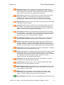
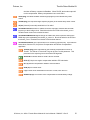
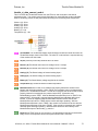
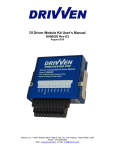
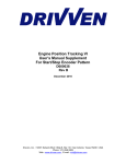
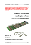
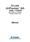
Throttle Driver Module Kit User’s Manual D000017 Rev B March 2012 Drivven, Inc. • 12001 Network Blvd, Bldg E, Suite 110 • San Antonio, Texas 78249 • USA Phone : 210.248.9308 Web : www.drivven.com , E-mail : [email protected] Drivven, Inc. Throttle Driver Module Kit Contents Introduction ......................................................................................................................... 3 Pinout .................................................................................................................................. 4 Hardware ............................................................................................................................. 5 Powering the Module .......................................................................................................... 5 Platform Compatibility ....................................................................................................... 6 H-Bridge Drivers ................................................................................................................ 8 Analog Inputs ...................................................................................................................... 8 Software Installer .............................................................................................................. 12 Creating a LabVIEW Project ............................................................................................ 14 Sub VI Documentation ..................................................................................................... 16 Throttle Control ................................................................................................................ 23 Compliance and Certifications .......................................................................................... 25 Physical Specifications and Characteristics ...................................................................... 26 © Drivven, Inc. 2009 • Throttle Driver Module Kit User’s Manual • D000017 • Rev B 2 Drivven, Inc. Throttle Driver Module Kit Introduction The Electronic Throttle Driver Module Kit provides a CompactRIO (cRIO) module for driving passenger car electronic throttle bodies up to 70mm in diameter. A typical example of electronic throttle bodies which this module is capable of driving is the Bosch DV-E5 series which range from 32mm to 68mm in diameter. However, the module is capable of driving most other electronic throttle bodies within that size range. The Electronic Throttle Driver Module Kit includes a LabVIEW FPGA VI for controlling two HBridge driver channels independently. Also provided are a set of RT VIs which allow the user to calibrate the throttle control algorithm in engineering units. The FPGA VI may be used by itself for driving any small DC motor other than an electronic throttle. However, this manual will focus on the application of electronic throttle position control. The features included are listed below: Features: 2-Ch. H-Bridge Drivers for dual electronic throttle control 2-Ch. analog input for throttle position feedback Short circuit and over-temperature protection with fault reporting Battery voltage, current sensing and module temperature measurements LabVIEW FPGA VI for h-bridge control and interface LabVIEW RT VI for electronic throttle position control External power supply of 6-32V © Drivven, Inc. 2009 • Throttle Driver Module Kit User’s Manual • D000017 • Rev B 3 Drivven, Inc. Throttle Driver Module Kit Pinout © Drivven, Inc. 2009 • Throttle Driver Module Kit User’s Manual • D000017 • Rev B 4 Drivven, Inc. Throttle Driver Module Kit Hardware The Electronic Throttle Driver Module Kit provides two H-Bridge drivers and analog position feedback in a National Instruments CompactRIO module. Powering the Module The Electronic Throttle Driver module requires power from two different sources. One source is from the CompactRIO backplane male high density D-Sub 15-pin (HD15) connector which mates with the module’s female HD15 connector. This power source provides a regulated 5 volts and ground to various digital logic functions within the module. The CompactRIO 5V source is active whenever the CompactRIO or R-Series Expansion Chassis is properly powered. The module should only be powered at the HD15 connector by plugging it into a CompactRIO or R-Series Expansion Chassis. The module’s HD15 connector should not be connected to any other device. Another required power connection is at the external screw terminal connector. The terminals are labeled BATT (0) and GND (9). Typical power sources will be from automotive 12V or 24V battery systems. However, the module can accept power from a range of 6V to 32V. With no throttles connected, the module requires up to 100mA from the external supply. Driving a single throttle under full load requires up to 60W peak and 30W continuous. Driving two throttles at full load requires up to 120W peak and 60W continuous. This module requires both external power and power from the CompactRIO backplane. The module is designed in such a way that the high current path is directed through the BATT (0) and GND (9) terminals on the front of the module and not through the HD15 backplane connector. The module will not be recognized by software without both power supplies active. Warning: The external battery supply input terminals are not reverse voltage polarity protected. Connecting power to the module in reverse polarity will damage the module. This event is not covered by the warranty. Please refer to the DrivvenReverseBatteryNotice.pdf document (available on the website) for a recommended solution for protecting a system from reverse battery polarity. © Drivven, Inc. 2009 • Throttle Driver Module Kit User’s Manual • D000017 • Rev B 5 Drivven, Inc. Throttle Driver Module Kit Platform Compatibility CompactRIO modules from Drivven are compatible within two different platforms from National Instruments. One platform is CompactRIO, consisting of a CompactRIO controller and CompactRIO chassis as shown in Figure 1a below. Figure 1a. CompactRIO platform compatible with Drivven CompactRIO modules. The other platform is National Instruments PXI which consists of any National Instruments PXI chassis along with a PXI RT controller and PXI-78xxR R-Series FPGA card. An R-Series expansion chassis must be connected to the PXI FPGA card via a SHC68-68-RDIO cable. The CompactRIO modules insert into the R-Series expansion chassis. This platform is shown in Figure 1b below. Figure 1b. PXI platform compatible with Drivven CompactRIO modules. Drivven CompactRIO modules are not compatible with the National Instruments CompactDAQ chassis. Drivven CompactRIO modules REQUIRE one of the hardware support systems described above in order to function. The modules may not be used by themselves and/or interfaced to third party devices at the backplane HD15 connector. These efforts cannot be supported by Drivven or National Instruments. You can use Drivven C Series modules with NI cRIO-911x, NI cRIO-907x, and NI R Series Expansion systems under the following conditions. –Leave one empty chassis slot between Drivven and NI modules. © Drivven, Inc. 2009 • Throttle Driver Module Kit User’s Manual • D000017 • Rev B 6 Drivven, Inc. Throttle Driver Module Kit –Maintain an ambient system operating temperature of 0 to 45 °C. –Typical specifications of NI modules may not apply when used in a system with Drivven modules. –Warranted specifications are guaranteed for all NI modules except thermocouple modules when used in a system with Drivven modules. –The NI 9214 is recommended for thermocouple measurements in cRIO systems using Drivven modules. –Scan Interface mode, auto-detection, and ID mode are not supported for Drivven modules. © Drivven, Inc. 2009 • Throttle Driver Module Kit User’s Manual • D000017 • Rev B 7 Drivven, Inc. Throttle Driver Module Kit H-Bridge Drivers The Electronic Throttle Driver Module Kit provides a CompactRIO (cRIO) module for driving passenger car electronic throttle bodies up to 70mm in diameter. A typical example of electronic throttle bodies which this module is capable of driving is the Bosch DV-E5 series which range from 32mm to 68mm in diameter. However, the module is capable of driving most other electronic throttle bodies within that size range. Each h-bridge circuit is capable of driving 3A continuously and 6A peak. It provides current sensing feedback as well as over-current and over-temp protection. In the case of a short circuit where 10A is exceeded, or a temperature of 140 C is exceeded within the driver FETs, a fault flag will be generated and the circuit will shutdown until the fault condition is removed. However, Drivven recommends monitoring the current and temperature values and disabling the circuit programmatically if current exceeds 6A or the internal module temperature exceeds 85 C. The temperature is automatically monitored within the throttle_rt_control.vi. Each h-bridge circuit automatically eliminates “shoot-through” current and provides internal clamp diodes for inductive loads. Analog Inputs The Electronic Throttle Driver Module provides two external analog inputs for accepting 0-5V signals. The primary purpose of these inputs is for measuring potentiometer voltages. A regulated 5V output and ground terminal is provided for powering the potentiometer(s) of an electronic throttle body. Warning: The 5V output is not protected against short circuit to higher voltage sources. Do not short this terminal to the H-Bridge driver terminals or BATT terminal. Other analog signals are also measured internal to the module and reported by the supplied VIs. All measured analog signals are listed below: Battery Voltage (V) H-Bridge 1 Current (A) H-Bridge 2 Current (A) H-Bridge 1 Fault Line (reported with boolean, T=Fault, F=No Fault) H-Bridge 2 Fault Line (reported with boolean, T=Fault, F=No Fault) External Analog Input 1 (0-5V, Screw Terminal 6) External Analog Input 2 (0-5V, Screw Terminal 7) Internal Module Temperature All eight analog inputs are sampled with a single multiplexed A/D converter at an aggregate rate of 17.84 KHz. Therefore each analog signal is sampled at 2.23 KHz. The A/D result can be used directly at the FPGA level in ADC counts, or at the RT level in converted engineering units. The external analog inputs are protected from -6V to +12V inputs. The external analog inputs are independent from throttle control algorithms, and may be used in any manner the user deems necessary. The intended purpose of the external analog inputs is for the convenience of connecting all wires of an electronic throttle directly to the module. Then the © Drivven, Inc. 2009 • Throttle Driver Module Kit User’s Manual • D000017 • Rev B 8 Drivven, Inc. Throttle Driver Module Kit user may programmatically use the analog values for throttle control feedback. Other analog inputs from another module may also be used to provide throttle position. Most electronic throttle bodies have redundant position signals. When using only one electronic throttle, both position signals may be connected to the module and redundant throttle position is available. However, when two electronic throttle bodies are used, only one position signal from each throttle may be connected to the module, and redundant throttle position is not available. However, the additional position signals may be connected to other analog inputs from other modules, making redundant throttle position available for both throttles. A redundant position algorithm must be provided by the user. Figure 2 and figure 3 below show the typical connections for controlling single or dual throttles, respectively. Table 1 below shows the module terminal connections to a standard Bosch DV-E5 electronic throttle body. Figure 2. Module terminal connections to a single electronic throttle body. © Drivven, Inc. 2009 • Throttle Driver Module Kit User’s Manual • D000017 • Rev B 9 Drivven, Inc. Throttle Driver Module Kit Figure 3. Module terminal connections to dual electronic throttle bodies. Table 1. Connection table specific for standard Bosch DV-E5 electronic throttle bodies Module Terminal DV-E5 Pin Description Description (Throttle1 / Throttle2) 1 Motor - T2 / T4 H1A / H2A 2 Potentiometer Ground T8 GND 3 Potentiometer Reference T5 5V Out 4 Motor + T1 / T3 H1B / H2B 5 Potentiometer 2 Signal T6 / T7 AN1 / AN2 6 Potentiometer 1 Signal T6 / T7 AN1 / AN2 © Drivven, Inc. 2009 • Throttle Driver Module Kit User’s Manual • D000017 • Rev B 10 Drivven, Inc. Throttle Driver Module Kit Standard Bosch DV-E5 electronic throttle bodies are available through Drivven according to the following part numbers list in table 2. Prices and availability vary. Table 2. Standard Bosch DV-E5 throttle bodies available through Drivven Throttle Body Diameter (mm) Bosch Part Number 32 0 280 750 148 40 0 280 750 149 60 0 280 750 151 68 0 280 750 152 The following connector parts for standard Bosch throttle bodies are available through Drivven if a throttle is purchased from Drivven. Otherwise they are available from major electronics component distributors such as Digikey, Mouser, Newark, Allied Electronics, etc. Table 3. Connector parts required for standard Bosch DV-E5 throttle bodies Connector Part Description AMP Part Number Connector Housing 1-967616-1 Crimp Socket Contact (Tin) 965906-1 Wire Seal 967067-1 © Drivven, Inc. 2009 • Throttle Driver Module Kit User’s Manual • D000017 • Rev B 11 Drivven, Inc. Throttle Driver Module Kit Software Installer The Electronic Throttle Driver Module Kit is provided with an installer package which may be downloaded from Drivven’s Sharepoint website after obtaining login access from Drivven. User’s may go to https://portal.drivven.com/SoftwareDownload and enter the provided username and password to gain access to the specific product installer packages which have been purchased. The installer packages are executables which should be run on the intended development computer, having LabVIEW development tools installed. After installing the package, a “Start>Programs->Drivven->ProductRelease” menu item will be added to the desktop. The specific product will have an example LabVIEW project appear under the “Examples” menu and the user manual will appear under the “Manuals” menu. User’s may copy and open the example project to experiment with the module or use as a starting point for a new application. All software files, example projects and documentation are installed to: C:\Program Files\National Instruments\LabVIEW X.X\vi.lib\addons\DrivvenProductRelease\. When working with block diagrams, user’s will notice a “Drivven” function palette added to the standard LabVIEW palette, specific for the RT or FPGA target. VIs for a specific Drivven product will be categorized according to product name. Also, some Drivven products will install RT and FPGA VIs under a “General” function palette which is intended to be used across multiple products. Requirements The Drivven VIs require: LabVIEW 8.5 Full Development or later LabVIEW RT Module 8.5 or later LabVIEW FPGA Module 8.5 or later NI-RIO 2.4 or later The Electronic Throttle Driver Module Kit is provided with both a LabVIEW FPGA VI for interfacing directly to the module and two LabVIEW RT VIs for interfacing with the FPGA VI and controlling throttle position. Figure 4 shows the icon which represents FPGA throttle_revx.vi. Figure 4. FPGA VI icon with leads. © Drivven, Inc. 2009 • Throttle Driver Module Kit User’s Manual • D000017 • Rev B 12 Drivven, Inc. Throttle Driver Module Kit Figure 5 shows the icon which represents throttle_rt_data_convert_revx.vi. This VI is used to convert raw data from the FPGA to engineering units at the RT level. The outputs from this VI should be wired to the throttle_rt_control.vi. Figure 5. Throttle Data RT VI icon with leads. Figure 6 shows the icon which represents throttle_rt_control.vi. This VI is used at the RT level and accepts engineering unit data from the throttle_rt_data_convert_revx.vi along with additional calibration values. One or two instances of this VI may be used, depending on the number of throttle driver channels being utilized. The resulting period and pulsewidth output values should be wired directly to the FPGA level to the throttle_revx.vi ThrottleControl cluster. Figure 6. Throttle Control RT VI icon with leads. The FPGA VI must be placed within a Single Cycle Loop (SCL) of a LabVIEW FPGA block diagram. The SCL must execute at the default clock rate of 40 MHz. The FPGA VI requires a pre-synthesized netlist file having a matching name and an extension of .ngc. The netlist file must be located in the same directory as the matching VI. The installer will place this file in the LabVIEW addons directory along with the FPGA VI. © Drivven, Inc. 2009 • Throttle Driver Module Kit User’s Manual • D000017 • Rev B 13 Drivven, Inc. Throttle Driver Module Kit Creating a LabVIEW Project Drivven recommends working from the provided example application as a starting point for learning the use of the Drivven software blocks. However, the following section describes starting a LabVIEW project from scratch and adding a Drivven module. 1.) Install the Drivven software by running the installer executable and accepting the software license agreement. 2.) Restart LabVIEW, if previously running, and create a new LabVIEW project. 3.) Give the new project a name by clicking the “Save Project” button on the project toolbar. 4.) Right click on the highest item in the project hierarchy (“Project:…”) and navigate to “New->Targets and Devices…” 5.) Within the “Add Targets and Devices…” dialog, select the appropriate radio button, depending on whether you already have an existing powered and configured RT target on the network or if you are adding a new RT target which is not present yet on the network. a. Existing Target or Device i. Expand the appropriate category in the “Targets and Devices” list to see the discovered targets in that category. ii. Double-click the desired target to add it to your project. b. New Target or Device i. Expand the appropriate category in the “Targets and Devices” list to see all possible targets within that category. ii. Double-click the desired target to add it to your project. 6.) If the new RT target is not currently on the network, right-click on the RT target within the project and open the properties dialog to set the IP address or DNS name if necessary. 7.) Right-click on the RT target within the project and navigate to “New->Targets and Devices…” 8.) Within the “Add Targets and Devices…” dialog, select the appropriate radio button, depending on whether you already have an existing FPGA target connected to an existing RT target or if you are adding a new FPGA target which is not present yet. a. Existing Target or Device i. Expand the appropriate category in the “Targets and Devices” list to see the discovered FPGA targets in that category. ii. Double-click the desired target to add it to your project. b. New Target or Device i. Expand the appropriate category in the “Targets and Devices” list to see all possible targets within that category ii. Double-click the desired target to add it to your project. 9.) If the new FPGA target was not currently in the system, right-click on the FPGA target within the project and open the properties dialog to set the resource name if necessary. The resource name can be found from MAX when connected to the actual remote system. 10.) If the FPGA target is a PXI or PCI card, then an R Series expansion chassis must be added under the FPGA target. This is done by right-clicking on the FPGA target and navigating to “New->R Series Expansion Chassis”. Within the following dialog, select the appropriate FPGA connector to which the chassis will be connected. A unique name for the chassis may also be specified. 11.) Right click on the R-Series expansion chassis or cRIO FPGA target chassis and navigate to “New->C Series Modules…” 12.) Select the “New Target or Device” radio button and double-click on the “C Series Module” in the “Targets and Devices” list. In the following dialog, select the desired Drivven module at the bottom of the “Module Type” list. The Drivven modules will be appended there if any Drivven module software has been installed. Select the appropriate module © Drivven, Inc. 2009 • Throttle Driver Module Kit User’s Manual • D000017 • Rev B 14 Drivven, Inc. Throttle Driver Module Kit location. Finally, specify an appropriate name for the module, which will later appear in the FPGA I/O nodes in the FPGA block diagram. Having meaningful module names is important for preventing coding mistakes. 13.) After adding a module to the project, a folder will automatically be added to the project having the same module name given in the module configuration dialog. The folder will contain the FPGA I/O pins for the module slot. These I/O pins can be selected in the block diagram when connecting the module VI PinInput and PinOutput clusters to FPGA I/O nodes. The example application, discussed below, should be consulted for further details about connecting the PinInput and PinOutput clusters to FPGA I/O nodes. Within the example projects, notice the FPGA I/O node elements having module name prefixes. 14.) Some Drivven modules can be automatically recognized by LabVIEW when adding cRIO modules to the project. However, Drivven does not recommend using this feature because the module names, which are automatically assigned, are not meaningful (Mod1, Mod2, etc) and can lead to coding mistakes when wiring the Drivven FPGA VIs to the I/O nodes. Adding the modules to the project manually, as described above, is still the recommended method. © Drivven, Inc. 2009 • Throttle Driver Module Kit User’s Manual • D000017 • Rev B 15 Drivven, Inc. Throttle Driver Module Kit Sub VI Documentation throttle_revb.vi This VI is for interfacing directly with the Drivven Throttle Driver module and for providing a control interface to the LabVIEW RT level. The FPGA VI must be placed within a Single Cycle Loop (SCL) of a LabVIEW FPGA block diagram. The SCL must execute at the default clock rate of 40 MHz. The FPGA VI requires a pre-synthesized netlist file having a matching name and an extension of .ngc. The netlist file must be located in the same directory as the matching VI. The installer will place this file in the LabVIEW addons directory along with the FPGA VI. The PinInput and PinOutput clusters are wired to LabVIEW FPGA I/O nodes which are configured for a cRIO controller chassis or a cRIO R-Series expansion chassis. Refer to the LabVIEW FPGA documentation for details about creating and configuring FPGA I/O nodes. Connector Pane Controls and Indicators ThrottleControl This cluster contains the main enable Boolean, watchdog Boolean and PWM parameters for each H-Bridge channel. ModuleEnable If a throttle driver module is inserted in the proper slot, externally powered, and ModuleEnable is TRUE, then software begins communicating with the module and allows the module to operate. When the module is properly recognized, then the ModulePresent Boolean within the ThrottleData cluster will be set to TRUE. WatchdogIn WatchdogIn must be toggled at a rate greater than or equal to 10Hz. This should only be performed at the RT level. DO NOT toggle the watchdog at the FPGA level. Toggling the watchdog at the FPGA level would bypass the software safety feature for which it is intended. Throttle1Period The time period between leading edges of the PWM pulse train to h-bridge circuit 1. Throttle1Period is entered in terms of 4 MHz clock ticks. This provide a maximum period of 8.192 milliseconds or a minimum frequency of 122 Hz, and a resolution of 250 nsec. Throttle2Period The time period between leading edges of the PWM pulse train to h-bridge circuit 2. Throttle2Period is entered in terms of 4 MHz clock ticks. This provides a maximum period of 8.192 milliseconds or a minimum frequency of 122 Hz, and a resolution of 250 nsec. Throttle1PulseWidth The time during each Throttle1Period in which the PWM pulse train to h-bridge circuit 1 is active. This value is signed, and represents direction of current flow through the h-bridge circuit. A positive value represents positive current flowing from terminal H1B to H1A. Throttle1PulseWidth is entered in terms of 4 MHz clock ticks. While Throttle1PulseWidth is 0, h-bridge circuit 1 will remain inactive. While Throttle1PulseWidth is greater than or equal to Throttle1Period, h-bridge circuit 1 will remain fully active. This condition © Drivven, Inc. 2009 • Throttle Driver Module Kit User’s Manual • D000017 • Rev B 16 Drivven, Inc. Throttle Driver Module Kit should be avoided. Otherwise an over-current or over-temp fault will result. Throttle2PulseWidth The time during each Throttle2Period in which the PWM pulse train to h-bridge circuit 2 is active. This value is signed, and represents direction of current flow through the h-bridge circuit. A positive value represents positive current flowing from terminal H2B to H2A. Throttle2PulseWidth is entered in terms of 4 MHz clock ticks. While Throttle2PulseWidth is 0, h-bridge circuit 2 will remain inactive. While Throttle2PulseWidth is greater than or equal to Throttle2Period, h-bridge circuit 2 will remain fully active. This condition should be avoided. Otherwise an over-current or over-temp fault will result. ThrottlePinInput These Boolean controls must be connected to their corresponding FPGA I/O Node input item. ThrottleData The ThrottleData cluster should be terminated with an indicator cluster and made available as a complete cluster for interfacing to the throttle_rt_data_convert_revx.vi at the RT level. No FPGA code interface is required with any of the members of this cluster. ThrottlePinOutput The Boolean indicator named IDSelectEn must be connected to a Set Output Enable method of an FPGA I/O Method Node. The Boolean indicator named IDSelectOut must be connected to a Set Output Data method of an FPGA I/O Method Node. The remaining Boolean indicators must be connected to their corresponding FPGA I/O Node output item. © Drivven, Inc. 2009 • Throttle Driver Module Kit User’s Manual • D000017 • Rev B 17 Drivven, Inc. Throttle Driver Module Kit throttle_rt_control.vi This VI implements electronic throttle position control at the RT level using three algorithms. The first algorithm is PID control using two sets of gains. One set of gains is for positions above ThetaLH and the other set is for positions below ThetaLH. The second control algorithm is to compensate the output for travel through the vicinity of the ThetaLH position, as there is a change in spring return force at that position. The third control algorithm is to compensate the output for stiction which is most effective while positional errors are small. Please refer to the context-help of the individual tuning parameters, as well as the user manual for tuning hints. The throttle_rt_control.vi (RT VI) and throttle_rt_data_convert_revx.vi must be placed within a while loop or timed loop and executed at a recommended rate of 100-200 Hz (5-10 msec period). This rate provides good throttle control capability. A reference must be opened to a LabVIEW FPGA application which implements the throttle_revx.vi. Also, FPGA read/write register functions must be placed within the RT loop to gain access to the ThrottleControl and ThrottleData clusters of the FPGA throttle_revx.vi. The values given by the throttle_rt_data_convert_revx.vi may be used for monitoring or control purposes. If the external analog inputs are used for position control feedback, then they must be converted to throttle angle by means of a transfer function or lookup table. Drivven provides a lookup table function in the rt_vi directory provided to all customers. The throttle angle in degrees should be input to the Theta (deg) input of the throttle_rt_control.vi. Temperature (C) The internal temperature of the module in degrees C, as calculated by the throttle_rt_data_convert_revx.vi. Battery (V) The battery voltage supplied to the module, as calculated by the throttle_rt_data_convert_revx.vi. ModulePresent Should be wired directly from the ModulePresent output of the throttle_rt_data_convert_revx.vi. ControlEnable When TRUE, the VI will generate active output values for the ThrottlePulseWidthTicks output. When FALSE, the VI will write 0 to the ThrottlePulseWidthTicks output. ThrottleCalibrations Collection of calibration parameters for controlling throttle position. TLead (sec) Adjusts the lead compensation on the ThetaR value. A lead/lag compensation function is internally inserted in the ThetaR signal to the internal PID function. TLead can be increased to intensify the change in ThetaR. TLag (sec) Adjusts the lag compensation on the ThetaR value. A lead/lag compensation function is internally inserted in the ThetaR signal to the internal PID function. TLag can be increased to slow the change in ThetaR. KRpos (V/deg) Proportional gain for the throttle control PID function while Theta is greater than ThetaLH. © Drivven, Inc. 2009 • Throttle Driver Module Kit User’s Manual • D000017 • Rev B 18 Drivven, Inc. Throttle Driver Module Kit TIpos (sec) Integral time for the throttle control PID function while Theta is greater than ThetaLH. The integral time is equivalent to the electro-mechanical time-constant of the throttle body. Smaller integral times intensify the integral action. When TI is set to zero, the integral action is disabled. TDpos (sec) Derivative time for the throttle control PID function while Theta is greater than ThetaLH. The derivative time is proportional to the electromechanical time-constant of the throttle body. Larger times intensify the derivative action. When TD is set to zero, the derivative action is disabled. KRneg (V/deg) Proportional gain for the throttle control PID function while Theta is less than or equal to ThetaLH. TIneg (sec) Integral time for the throttle control PID function while Theta is less than ThetaLH. The integral time is equivalent to the electro-mechanical timeconstant of the throttle body. Smaller integral times intensify the integral action. When TI is set to zero, the integral action is disabled. TDneg (sec) Derivative time for the throttle control PID function while Theta is less than ThetaLH. The derivative time is proportional to the electro-mechanical time-constant of the throttle body. Larger times intensify the derivative action. When TD is set to zero, the derivative action is disabled. ThetaLHErrThresh (deg) Limp-home compensation (uLHc) is updated when ThetaR is within ThetaLHErrThresh degrees of ThetaLH (above or below). ULH (V) Voltage added or subtracted to the PID output when ThetaR is in the vicinity of ThetaLH. As Theta moves through the limp-home region, ULHc is updated to a positive or negative value (negative going down, positive going up) and added to the PID output in order to assist throttle control through the region. ULHLag (sec) Lag filter time applied to the limp-home compensation. A lag time prevents uLHc from reversing directions too fast. US (V) Voltage added to or subtracted from the PID output when Theta is outside the vicinity of ThetaLH. US is a stiction compensation value. This parameter assists throttle control during small Theta errors to overcome stiction. Parameter uFc is updated to a positive or negative value according to the sign of ThetaR - Theta error, and added to the PID output. USLag (sec) Lag filter time applied to the stiction compensation. A lag time prevents uFc from reversing directions too fast. ThetaLH (deg) Limp-home angle. This is the default throttle position which results from no power being applied to the motor. MotorResistance (Ohms) The resistance of the motor winding must be entered here. A digital multi-meter (DMM) can be used to measure this. This value is used to determine output ranges. BattNom (V) The nominal battery voltage supplied to the module. Most automotive systems operate with 12V. This would be the nominal battery voltage. The actual voltage may fluctuate around the nominal. BattCompEnable When TRUE, the VI will compensate the throttle output for the © Drivven, Inc. 2009 • Throttle Driver Module Kit User’s Manual • D000017 • Rev B 19 Drivven, Inc. Throttle Driver Module Kit deviation of Battery compared to BattNom. When FALSE, the throttle output will not be compensated. Battery compensation has a small effect. Theta (deg) The latest feedback throttle angle (degrees) of the throttle body under control. ThetaR (deg) The requested angle setpoint (degrees) of the throttle body under control. dt (sec) Interval (in seconds) at which this VI is called. ThrottlePeriodTicks Number of 4 MHz clock ticks required to achieve 500 Hz PWM frequency to the h-bridge circuit. Should be wired to the FPGA to the throttle_revx.vi ThrottleControl cluster for the desired channel. ThrottlePulseWidthTicks Signed integer of 4 MHz clock ticks required to achieve the PWM duty cycle calculated by the throttle_rt_control.vi. Should be wired to the FPGA to the throttle_revx.vi ThrottleControl cluster for the desired channel. ThrottleControlCalcs This output cluster is for monitoring purposes only. It provides the latest values from the PID, Limp-Home Compensation and Stiction Compensation algorithms. ThetaFF (deg) Value calculated by the Lead/Lag compensator function on ThetaR. The effects of TLead and TLag can be seen on this parameter. This parameter is the setpoint given to the throttle PID algorithm. AboveLH? Indicates whether Theta is above ThetaLH. uLHc (V) Limp-home region compensation added to PID calculation. uFc (V) Stiction compensation added to PID calculation. uPID (V) PID control result. u (V) Control value calculated from the sum of uPID, uLHc and uFc. uBattComp (V) Final control value compensated for actual battery voltage. © Drivven, Inc. 2009 • Throttle Driver Module Kit User’s Manual • D000017 • Rev B 20 Drivven, Inc. Throttle Driver Module Kit throttle_rt_data_convert_revb.vi This VI receives the ThrottleData cluster from the FPGA VI and converts the raw data to engineering units. The module presence and fault status for each H-Bridge are also indicated. Each of the analog values are low-pass filtered according to the following cutoff frequencies: ISense1 (V): 25 Hz ISense2 (V): 25 Hz Analog1 (V): 25 Hz Analog2 (V): 25 Hz Battery (V): 1 Hz Temperature (C): 1 Hz ThrottleData The ThrottleData Cluster input should be fed with the cluster wire from the ThrottleData output cluster of the FPGA. No other RT code interface is required with any of the members of this cluster. dt (sec) Interval (in seconds) at which this VI is called. ISense1 (A) The filtered load current of h-bridge circuit 1 in amps. ISense2 (A) The filtered load current of h-bridge circuit 2 in amps. Analog1 (V) The filtered voltage of external analog input 1. Analog2 (V) The filtered voltage of external analog input 2. Battery (V) The filtered battery voltage supplied to the module. Temperature (C) The filtered internal module temperature. ModulePresent When TRUE, then software has properly detected a Throttle Driver Module and can begin operation. When FALSE, then software has not yet detected the presence of a Throttle Driver Module. In order to be detected, the driver module must be properly inserted in its assigned slot, powered at the BATT (0) terminal, and ModuleEnable must be TRUE. After the ModulePresent Boolean is set to TRUE, if the power at BATT (0) terminal is removed then the ModulePresent Boolean will reset to FALSE. If power is reapplied while ModuleEnable Boolean remains TRUE, then ModulePresent will return to TRUE and the module will begin operating. After the ModulePresent Boolean is set to TRUE, if the module is removed from its slot, then the ModulePresent Boolean will be set to FALSE. If the module is reinserted, then it will be detected again and begin operating. ModulePresent should be wired directly to the ModulePresent input of the throttle_rt_control.vi. Fault1 When TRUE, then an over-current or over-temperature fault has occurred with hbridge circuit 1 and operation will be interrupted until the fault is removed. © Drivven, Inc. 2009 • Throttle Driver Module Kit User’s Manual • D000017 • Rev B 21 Drivven, Inc. Throttle Driver Module Kit Fault2 When TRUE, then an over-current or over-temperature fault has occurred with hbridge circuit 2 and operation will be interrupted until the fault is removed. © Drivven, Inc. 2009 • Throttle Driver Module Kit User’s Manual • D000017 • Rev B 22 Drivven, Inc. Throttle Driver Module Kit Throttle Control Drivven provides a flexible throttle position control algorithm with the Throttle Driver Module Kit. Please follow the throttle control example provided for implementing throttle control in your engine control application. Drivven recommends performing throttle control at a rate of 100-200 Hz. Even if your engine control algorithms require execution at another rate, a separate timed loop can be created to implement throttle control. The throttle control VI uses position values in terms of degrees. However, percentages can be used instead. This document does not go into detail about the procedures for tuning a typical PID loop. There are many texts available which cover that topic. It is expected that the user of this module kit be familiar with PID control concepts. The throttle control algorithm calculates a final voltage to be applied to the throttle body DC motor. The final voltage is applied by means of a PWM duty cycle, with battery voltage being the maximum possible voltage. The control voltage may be compensated for actual battery voltage, ass deviating from the nominal battery voltage, according to BattCompEnable. The compensated voltage is converted to a signed PWM duty cycle at a fixed frequency of 500 Hz. The throttle control VI output results are in terms of 40 MHz clock ticks to be wired to the FPGA period and pulse width parameters. The throttle control algorithm involves 4 major functions: 1.) The angle setpoint (reference), ThetaR is compensated by a user defined lead and lag time. These parameters will sharpen or dull the changes in setpoint. 2.) A proportional, integral and derivative action is calculated based on two sets of PID gains, above or below the default limp-home region. The reason for two sets of gains is because electronic throttle bodies typically have stiffer spring return rates applied to angles below the limp-home region. 3.) A limp-home compensation value is added to the PID value to assist with travel through the limp-home region. This compensation can minimize the flat control spot often found as the throttle plate moves through the limp-home region. 4.) A stiction compensation value is added to the PID value to assist with small error control. When the throttle plate approaches the setpoint, stiction in the throttle motor gearing can be significant enough such that PID control alone will cause integral overshoot. Stiction compensation will apply small alternating forces to assist the PID integral action. 5.) Battery voltage compensation is optionally added to the final output to compensate for battery voltage fluctuations away from the nominal voltage. In general, the final voltage u (V) is a sum of 3 components and optionally multiplied by a battery compensation factor: u (V) = [ PID(V) + Stiction Comp(V) + Limp-Home Comp(V) ] * Battery Comp Factor The first calibration which the user should tune is throttle angle versus sensor voltage. A linear equation can be used, as well as a two-point 1D lookup table. Manually close the throttle plate completely to determine the minimum sensor voltage. If the radii of the throttle body opening and the throttle plate are measured, then the minimum throttle angle can be calculated by using an inverse cosine calculation, or by approximating the small angle with sine. Manually open the throttle plate to wide-open-throttle, noting the maximum sensor voltage. Assume the wide-openthrottle angle to be 90 degrees. After calibrating for position versus voltage, enter the value for ThetaLH (default limp-home position). It is recommended that the sensor voltages entered into the position calibration for the upper and lower limits be slightly narrowed so that position control at these points does not overwork the driver, trying to achieve positions that are not possible as sensing conditions change. Another way to prevent this condition is to limit the setpoint range to © Drivven, Inc. 2009 • Throttle Driver Module Kit User’s Manual • D000017 • Rev B 23 Drivven, Inc. Throttle Driver Module Kit a small position away from the physical limits. It is recommended that a filter be implemented on throttle position. A second order, lowpass Butterworth filter with a cuttoff frequency of 25Hz is suggested. The filter is most effective during small-error control. Please note that the throttle_rt_data_convert_revx.vi already implements a 25 Hz filter on the analog input voltages. Therefore, if this VI is used for position, then a filter is not required. It is recommended that the user begin control calibration with zero for all Lead/Lag, PID and compensation calibration parameters. Begin tuning PID gains for angles above ThetaLH. Then introduce TLead and TLag values as necessary. Then begin tuning PID gains for angles below ThetaLH. ULH and US compensation should be tuned last. The default values saved for the example application were derived for a 68mm Bosch DV-E5 throttle body. The default values will work well for smaller throttle bodies, with minor adjustments. Note: ThetaR should not be allowed to exceed the minimum and maximum angles of the throttle. This will force the controller to drive more current than the throttle or module can sustain. The force exerted may also mechanically damage the throttle body. © Drivven, Inc. 2009 • Throttle Driver Module Kit User’s Manual • D000017 • Rev B 24 Drivven, Inc. Throttle Driver Module Kit Compliance and Certifications Safety This product meets the requirements of the following standards of safety for electrical equipment for measurement, control, and laboratory use: IEC 61010-1, EN 61010-1 UL 61010-1, CSA 61010-1 Electromagnetic Compatibility This product meets the requirements of the following EMC standards for electrical equipment for measurement, control, and laboratory use: EN 61326-1 (IEC 61326-1): Class A emissions; Industrial immunity EN 55011 (CISPR 11): Group 1, Class A emissions AS/NZS CISPR 11: Group 1, Class A emissions FCC 47 CFR Part 15B: Class A emissions ICES-001: Class A emissions Caution: When operating this product, use shielded cables and accessories. CE Compliance This product meets the essential requirements of applicable European Directives as follows: 2006/95/EC; Low-Voltage Directive (safety) 2004/108/EC; Electromagnetic Compatibility Directive (EMC) Environmental Management NI is committed to designing and manufacturing products in an environmentally responsible manner. NI recognizes that eliminating certain hazardous substances from our products is beneficial to the environment and to NI customers. For additional environmental information, refer to the NI and the Environment Web page at ni.com/environment. This page contains the environmental regulations and directives with which NI complies, as well as other environmental information not included in this document. Waste Electrical and Electronic Equipment (WEEE) EU Customers At the end of the product life cycle, all products must be sent to a WEEE recycling center. For more information about WEEE recycling centers, National Instruments WEEE initiatives, and compliance with WEEE Directive 2002/96/EC on Waste Electrical and Electronic Equipment, visit ni.com/environment/weee. Battery Replacement and Disposal Battery Directive This device contains a long-life coin cell battery. If you need to replace it, use the Return Material Authorization (RMA) process or contact an authorized National Instruments service representative. For more information about compliance with the EU Battery Directive 2006/66/EC about Batteries and Accumulators and Waste Batteries and Accumulators, visit ni.com/environment/batterydirective. © Drivven, Inc. 2009 • Throttle Driver Module Kit User’s Manual • D000017 • Rev B 25 Drivven, Inc. Throttle Driver Module Kit Management Methods for Controlling Pollution Caused by Electronic Information Products Regulation (China RoHS) Chinese Customers National Instruments is in compliance with the Chinese policy on the Restriction of Hazardous Substances (RoHS) used in Electronic Information Products. For more information about the National Instruments China RoHS compliance, visit ni.com/environment/rohs_china. 电子信息产品污染控制管理办法( 中国RoHS) 中国客户 National Instruments符合中国电子信息产品中限制使用某些有害物质指令 (RoHS)。 关于National Instruments中国RoHS合规性信息,请登录 ni.com/environment/rohs_china。(For information about China RoHS compliance, go to ni.com/environment/rohs_china.) Ferrite Requirement for EMC Compliance Install clamp-on ferrite beads onto both the power supply cable and the signal cables. Power to the module must be off when adding ferrites. Ferrites must be connected to the power cable and the signal cable as close to the module as possible. Placing the ferrite elsewhere on the cable noticeably impairs its effectiveness. Determine the clamp-on ferrite beads to install based on your application. Use the following ferrites or other similar ferrites: Power cables to CompactRIO and module: Laird 28A0592-0A2 (2 total) AN1, AN2, GND: Wurth Electronics 7427154 (four turns through ferrite) H1B, H1A, H2B, H2A: Wurth Electronics 7427154 (four turns through ferrite) Physical Specifications and Characteristics Weight: 145 grams Maximum Altitude: 2000 m Operating Temperature: -40° C to 70° C Maximum Ambient Temperature: 60º C Operating Humidity: 10% to 90% RH, noncondensing Pollution Degree: 2 Ingress Protection: IP30 For Indoor Use Only If you need to clean the module, wipe it with a dry towel Safety Guidelines Caution: Do not operate this module in a manner not specified in these operating instructions. Product misuse can result in a hazard. You can compromise the safety protection built into the product if the product is damaged in any way. If the product is damaged, return it to National Instruments for repair. © Drivven, Inc. 2009 • Throttle Driver Module Kit User’s Manual • D000017 • Rev B 26