1
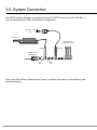
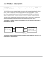
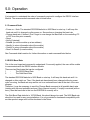
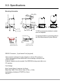
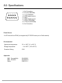
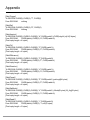
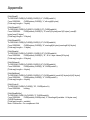
Series 956
RS232 Interface Module
user manual
1.0: Index
Section Title
Page
1.0
Index . . . . . . . . . . . . . . . . . . . . . . . . 2
2.0
Introduction . . . . . . . . . . . . . . . . . . . 3
3.0
System Connection . . . . . . . . . . . . . 4
4.0
Product Description . . . . . . . . . . . . . 5
5.0
Operation . . . . . . . . . . . . . . . . . . . . 6
5.1 Command Order . . . . . . . . . . . . 6
5.2 RS232 Baud Rate . . . . . . . . . . . 6
6.0
RS232IM Specific Commands . . . . . 7
7.0
Code Examples . . . . . . . . . . . . . . . . 9
7.1 Quick Basic . . . . . . . . . . . . . . . . 9
7.2 Low Level . . . . . . . . . . . . . . . . . 11
8.0
Specifications . . . . . . . . . . . . . . . . . 15
Appendix . . . . . . . . . . . . . . . . . . . . . . . . . . . . 17
Return of Goods
Solartron Offices
Part No. 502030 issue 7.1
2.0: Introduction
This manual is provided as a supplement to the standard ‘Network Card and Driver’ manual.
The ‘Network Card and Driver’ manual is primarily intended for systems based around the Orbit
Network Card. Therefore, sections 1, 2 and 3 are not particularly relevant to a RS232IM system.
The remainder of the manual gives full information on Orbit Commands, error codes etc.
Two variants of the standard product are available, the only difference being the default RS232
Baud rate on switch on. These variants are provided for users with PLCs that have limited RS232
Baud rate options.
For the standard RS232IM, the default is 9600Baud.
For the 911301 variant, the default is 57.6kBaud
For the 911338 variant, the default is 115.2kBaud
Orbit Measurement System Software and Documentation CD (Part No. 510266) contains setup.
exe to install drivers for WIN98/ME/2000/NT/XP and also contains Orbit_dos folder for DOS users.
Note: Cover picture shows RS232IM together with PSIM (Power Supply Interface Module).
Part No. 502030 Issue 7.1
3.0: System Connection
The RS232 Interface Module is not powered from the PC RS232 comm port or the Orbit Bus. It
must be powered from a PSIM. See below for configuration.
PC RS232 comm
port
90 - 240 V ac
input
Standard Orbit
Modules and T-CON
RS232IM
PSIM
DO NOT connect
Orbit Network
plug
side
socket
side
Refer to the Orbit Network Measurement System for detailed information on Orbit Network electrical requirements.
Part No. 502030 issue 7.1
4.0: Product Description
The RS232IM is designed to act as a bridge between any device with a full duplex RS232 serial
port and the Orbit Network.
The RS232IM receives a command header string and an Orbit command string from the ‘Master’
device. It then re-transmits the Orbit command string to the Orbit network @ 187.5 kBaud.
Note. Due to bandwidth limitations on the RS232 comm port, the RS232IM is not Orbit High
Speed or Dynamic capable. For these functions, the Orbit PCI Network Card should be used.
The Orbit module processes the command and returns a reply (if appropriate) to the RS232IM
which then adds a reply header and transmits both header and reply to the ‘Master’.
The production of the break character and the handling of the Orbit message turn around are all
performed by the RS232IM.
Master device Tx
Rx RS232IM A
(PC, PLC etc.)
RS232
Orbit
Rx
Tx
B
A
Orbit Module(s)
(Digital Probe,
B Linear Encoder etc)
RS485
Half Duplex
The command and reply header strings contain information which is used by the RS232IM to control and report on the Orbit Network.
Part No. 502030 Issue 7.1
5.0: Operation
It is important to understand the order of commands required to configure the RS232 Interface
Module. The recommended command order is listed below.
5.1 Command Order
• Power on – Note: The standard RS232IM defaults to 9600 Baud on start-up. It will keep this
baud rate until it is changed or after power-on. See section on changing the baud rate.
• Change baud rate, if desired. (Don’t forget to now change the Baud rate on the controlling PC
or PLC from this point onwards).
• Reset
• Notify (if desired)
• Setaddr (to set the module up at an address)
• Identify (to return information about the module)
• Getinfo (to return information about the module)
• Read1 or Read2 (to read module)
See Command details section for further information on each command listed below.
5.2 RS232 Baud Rate
This is the most important command to understand. If incorrectly applied, the user will be unable
to communicate with the RS232 Interface Module.
There are two Baud rates that can be configured.
1
-
The RS232 Baud Rate
2
-
The Orbit Baud Rate
The standard RS232IM defaults to 9600 Baud on start-up. It will keep this baud rate until it is
changed or after switch on. Thus, if the baud rate has already been changed without a power
cycle occurring, the Baud rate may well be set to an unknown baud rate at the start of the user
program.
Therefore, it may be necessary to send the Change Baud command at all possible baud rates
(starting with the most probable) and see if they respond correctly. If a reply is received (with no
error), then that baud rate is the one the RS232IM is currently set to.
The Orbit Baud Rate defaults to 187500 Baud, this should always be used. The 9600 Baud rate
should not be used for any new installations. It is only provided for backwards compatibility with
an older product range and it will be obsoleted in the future.
Part No. 502030 issue 7.1
6.0: RS232IM Specific Commands
There are two RS232 Interface Module configuration commands. These are used to set the
RS232 and Orbit Baud Rates and to put the module in ‘Idle’ mode to allow another Module to act
as the controller on the Orbit Network (eg an Encoder Input Module).
These are as follows:
Setup interface (RS232 and Orbit) – Command Type 6
String received by RS232IM on RS232 Rx (9 pin D skt pin 3).
To RS232IM:
Byte 1
Cmd byte–10 (0A Hex)
RS232IM command
byte
Byte 2
RS232 settings
RS232 Baud rate /
handshake
Byte 3
Orbit speed
Orbit Baud rate
String transmitted from RS232IM on RS232 Tx (9 pin D skt pin 2).
From RS232IM:
Byte 1
Status byte
RS232IM status
Byte 2
Byte count, always = 0
Number of bytes in Orbit reply
Notes:
1] If the ‘RS232 settings’ and ‘Orbit speed’ codes are valid the RS232IM will be set to the new
values after the status byte and byte count have been transmitted.
2] The status byte and byte count are transmitted at the same Baud rate as the received co
mand.
Setup Codes
RS232 settings. (byte 2 in String received by RS232IM).
This byte is used to set the RS232 Baud rate and handshaking, the Baud rate code selects the
rate at which the RS232IM will operate after the command has been acknowledged.
Hardware handshaking (CTS/RTS) can be turned on/off by setting/clearing the MS bit of the in
RS232 Settings byte, hence:
If handshaking is required,
If no handshaking is required, Part No. 502030 Issue 7.1
RS232 Settings byte = Baud rate code + 128 RS232 Settings byte = Baud rate code 6.0: RS232IM Specific Commands
RS232 settings. (byte 2 in String received by RS232IM).
Baud rate codes
0
RS232_DefltBaud - 9600, RS232IM is set to this rate and no handshaking at power
on.
1
RS232_9600
2
RS232_19200
3
RS232_28800
4
RS232_38400
5
RS232_57600
6
RS232_115200
Orbit speed (byte 3 in String received by RS232IM).
This byte is used to set the Orbit Baud rate. Currently only 9600 Baud and 187.5k Baud are available, the other codes are reserved for future expansion.
The 9600 Baud rate should not be used for any new installations. It is only provided for backwards
compatibility with an older product range and it will be obsoleted in the future.
0
1
2
3
RS485_DefltBaud - currently 187.5k, RS232IM is set to this rate at power on
RS485_187500
RS485_9600
reserved for future expansion
RS232 Setup interface - status codes. (byte 1 in String transmitted from RS232IM).
0
7
8
OK - RS232 Settings byte and Orbit speed byte both valid
bad RS232 Settings byte
bad Orbit speed byte
Set RS232IM Orbit interface to ‘Idle’ – Command Type 9
Used when another Module is to act as the controller on the Orbit Network
String received by RS232IM on RS232 Rx (9 pin D skt pin 3).
To RS232IM:
Byte 1
Cmd byte – 16 (10 Hex)
RS232IM command byte
String transmitted from RS232IM on RS232 Tx (9 pin D skt pin 2).
From RS232IM:
Byte 1
Byte 2
Status byte
Byte count
0
0
Part No. 502030 issue 7.1
7.0: Code Examples
The RS232IM command byte must always be the first byte sent to the RS232IM, it determines what
actions are to be performed, it also dictates the meaning of the remaining bytes in the command
header.
The information below describes each type of RS232IM command and the meaning of all the bytes
in the command and reply headers.
7.1 Quick Basic Examples:
Examples are written in Quick Basic, #1 is an open Com port set to 9600 Baud, 8 data bits, no parity.
Command Type 6 - Setup interface (RS232 and Orbit)
String received by RS232IM on RS232 Rx (9 pin D skt pin 3).
To RS232IM:
Byte 1
Byte 2
Cmd byte–10 (0A Hex)
RS232 settings
RS232IM command byte RS232 Baud rate / handshake
Byte 3
Orbit speed
Orbit Baud rate
String transmitted from RS232IM on RS232 Tx (9 pin D skt pin 2).
From RS232IM:
Byte 1
Byte 2
Status byte
Byte count, always = 0
RS232IM status
Number of bytes in Orbit reply
Command Type 6 example: Set RS232IM to RS232 9600 with handshaking and Orbit speed
187.5kB
RS232Settings$ = CHR$(1 + 128)
OrbitSpeed$ = CHR$(1)
msg$ = CHR$(10) + RS232Settings$ + OrbitSpeed$
PRINT #1, msg$;
Reply$ = INPUT$(2,#1)
Remember to change the baud rate of your serial port to the new rate from this point onwards.
Command Type 1 - Send Orbit message, no reply
String received by RS232IM on RS232 Rx (9 pin D skt pin 3).
To RS232IM:
Byte 1
Byte 2
Byte 3 - 257(max)
Cmd byte - 0
Cmd Length
Cmd String
RS232IM command byte Length of Orbit Cmd string Orbit command string
String transmitted from RS232IM on RS232 Tx (9 pin D skt pin 2).
From RS232IM:
NO REPLY
Part No. 502030 Issue 7.1
7.0: Code Examples
Command Type 1 - Example - Send OrbitRst command.
OrbitString$=”R”+CHR$(0)
msg$ = CHR$(0)+CHR$(LEN(OrbitString$))+ OrbitString$
PRINT #1, msg$;
Command Type 2 - Send Orbit message, wait for reply
String received by RS232IM on RS232 Rx (9 pin D skt pin 3).
To RS232IM: Byte 1
Byte 2
Byte 3
Cmd byte - 2
Reply Length
Cmd Length
RS232IM command byte
Length of Orbit Reply string
Length of Orbit Cmd string
String transmitted from RS232IM on RS232 Tx (9 pin D skt pin 2).
From RS232IM: Byte 1
Byte 2
Status byte
Byte count
RS232IM / Orbit Status
Byte 4- 258(max)
Cmd String
Number of bytes in Orbit reply
Orbit Cmd string
Byte 3- 257(max)
Reply string
Orbit reply string
Command Type 2 - Example Send OrbitSetaddr command to Orbit module M892780 - 36 (set
module to address 1)
oaddr% = 1
id$ = “M892780-36”
msg$ = CHR$(2) + CHR$(2) + CHR$(13) + “S” + CHR$(oaddr%) + id$ + CHR$(0)
PRINT #1, msg$;
status$ = INPUT$(1,#1)
IF status$ = chr$(0) THEN
count = asc(INPUT$(1,#1))
Reply$ = INPUT$(count,#1)
END IF
Command Type 8 - Send Orbit message (wait for variable length reply)
String received by RS232IM on RS232 Rx (9 pin D skt pin 3).
To RS232IM:
Byte 1
Byte 2
Cmd byte - 14
Cmd Length
RS232IM command byte
Length of Orbit Cmd string
String transmitted from RS232IM on RS232 Tx (9 pin D skt pin 2).
From RS232IM:
Byte 1
Byte 2
Status byte
Byte count
RS232IM / Orbit Status
10
Number of bytes in Orbit reply
Byte 3 - 257
Cmd String
Orbit Cmd string
Byte 3- 257(max)
Reply string
Orbit reply string
Part No. 502030 issue 7.1
7.0: Code Examples
Command Type 8 - Example - Send OrbitReadbuffer1 command to Orbit module
oaddr% = 1
msg$ = CHR$(14) + CHR$(2) + “2” + CHR$(oaddr%)
PRINT #1, msg$;
status$ = INPUT$(1,#1)
IF status$ = chr$(0) THEN
count = asc(INPUT$(1,#1))
Reply$ = INPUT$(count,#1)
END IF
7.1 Low Level Examples
Example of typical low level instructions follows:
Syntax:
0x is used to signify a value in hex (e.g. 0x0A = 10 decimal)
Change Baud Rate
Example change from 9600 (default) to 115200 Baud
Send:
• 0x0A (Set-up command)
• 0x06 (115200 Baud, no handshaking)
• 0x01 (187.5k Orbit Speed)
Reply:
• 0x00 => No Error
Remember to change the baud rate of your serial port to the new rate from this point onwards.
Reset command
Send:
• 0x00 = Command type
• 0x02 = NumChars to send
• 0x52 (= ‘R’)
• 0x00
There is no reply to this command.
Part No. 502030 Issue 7.1
11
7.0: Code Examples
Notify Command
Send a Notify command if you wish to find the Orbit identity of a particular module. If the Orbit identity is already known, proceed to the Setaddr stage.
Keep on Notifying & move tip until a reply is seen.
Send:
• 0x02 = Command type
• 0x0B = NumChars to receive
• 0x02 = NumChars to send
• 0x4E ( = ‘N’ = notify command)
• 0x00
Reply:
• 1 Byte Status Byte
• 1 Byte NumChars
• ReplyString
Status Byte = 0xFF implies that no module has been notified (time-out). No characters are returned,
so NumChars is set to 0. Nothing will be sent in ReplyString.
Send another Notify command in a loop until a module identity is successfully returned.
Status Byte = 0x00 implies that a module has successfully been notified. The Orbit identity and an
acknowledge byte are sent back, so NumChars is set to 11. ReplyString will contain ‘N’ followed by
the ten character Orbit identity for the module notified.
• 0x00 = Status Byte
• 0x0B = NumChars to be received
• ‘N’ = Acknowledge byte
• 10 Char Identity
12
Part No. 502030 issue 7.1
7.0: Code Examples
SetAddr Command
Once the module’s identity is known, set it up at an address from 1 to 31.
Send:
• 0x02 = Command type
• 0x02 = NumChars to receive
• 0x0D = NumChars to send
• 0x53 ( = ‘S’ = SetAddr command)
• 0x01 = Address to set to
• Ten character identity
• 0x00
Reply:
• 0x00 = Status Byte
• 0x02 = NumChars
• ‘S’ = Acknowledge Byte
• 0x00 = Address previously set to
If the identity is not found, the ErrorStatus will be set to 0xFF (timeout) and NumChars will be set to
0x00. No acknowledge byte or previous address will be returned.
Identify
Send:
• 0x02 = Command type
• 0x1E = NumChars to receive
• 0x02 = NumChars to send
• 0x49 ( = ‘I’ = Identify command)
• 0x01 = address to talk to
Reply:
• 0x00 = Status Byte
• 0x1E = NumChars
• ‘I’ = Acknowledge Byte
• 10 character identity
• 12 character device type
• 5 byte version
• 2 byte (16 bit) integer stroke (Least Significant Byte sent first)
Part No. 502030 Issue 7.1
13
7.0: Code Examples
GetInfo
Send:
• 0x02 = Command type
• 0x29 = NumChars to receive
• 0x02 = NumChars to transmit
• 0x42 ( = ‘B’ = Getinfo command)
• 0x01 = address to talk to
Reply:
• 0x00 = Status Byte
• 0x29 = NumChars
• ‘B’ = Acknowledge Byte
• 4 character Module type
• 2 byte (16 bit) integer hardware type (Least Significant Byte sent first)
• 2 byte (16 bit) integer resolution (Least Significant Byte sent first)
• 32 character Module Info
Read1
Send:
• 0x02 = Command type
• 0x03 = NumChars to receive
• 0x02 = NumChars to transmit
• 0x31 ( = ‘1’ = Read1 command)
• 0x01 = address to talk to
Reply:
• 0x00 = Status Byte
• 0x03 = NumChars
• ‘1’ = Acknowledge Byte
• 2 byte (16 bit) integer reading (Least Significant Byte sent first)
Read2
Send:
• 0x02 = Command type
• 0x05 = NumChars to receive
• 0x02 = NumChars to transmit
• 0x4C ( = ‘L’ = Read2 command)
• 0x01 = address to talk to
Note:
Using Read 1 or Read 2 with a Digital Probe in
Underrange or Overrange conditon will return
0x21 for the Acknowledge Byte and the
following byte will be 0x12 for Underrange or
0x13 for Overrange. Further bytes are to be
ignored.
Reply:
• 0x00 = Status Byte
• 0x05 = NumChars
• ‘L’ = Acknowledge Byte
• 4 byte (32 bit) integer reading (Least Significant Byte sent first)
14
Part No. 502030 issue 7.1
8.0: Specifications
∅ 0.335” x 90°
∅ 8.5mm x 90°
COUNTERSINK
1.390”
35.3mm
3.953”
100.4mm
0.157 ” 4.0mm
MIN BEND RADIUS
0.906”
23.0mm
2.394”
60.8mm
9
5
2.913 ±0.020”
74.0 ±0.5mm
WASHER
0.319”
8.1mm
MAX. SCREW INSERTION DEPTH
0.394”
10.00mm
Mounting Information
3.425” Max.
87.0mm Max.
M4 SCREW
MOUNTING OPTION
USING CAPTIVE NUTS
9
5
6
1
T-CON is permanently attached, module
does not separate.
17.3mm
0.681”
0.492”
12.5mm
1.890”
48.0mm
0.681”
17.3mm
M4
∅ 0.177”
∅ 4.5mm
1
For more information on mounting refer to
the Orbit Measurement System Manual.
T-CON BASE PADS
0.945”
24.0mm
6
MOUNTING OPTION
USING PLASTIC FEET
RS232C Connector (9 pin female D on flying lead)
The connector is designed to plug straight in to a 9 pin PC serial port.
The pin designations shown below refer to the meaning of that pin at the
output of the PC.
A special adapter may be required if the RS232IM is being used with a non
PC interface.
Port Settings
Byte Format: Binary, 8 data bits, No Parity.
Baud Rate: 9600, 19.2k, 28.8k, 38.4k, 57.6k or 115.2k
Handshaking: Hardware (CTS/RTS) or None.
Stop bit : 1
Part No. 502030 Issue 7.1
15
8.0: Specifications
6
1
7
2
8
3
9
4
5
1 = No Connection
2 = Rx (from RS232IM)
3 = Tx (to RS232IM)
4 = DTR (linked to pin 6)
5 = GND
6 = DSR (linked to pin 4)
7 = RTS (to RS232IM)
8 = CTS (from RS232IM)
9 = No Connection
Power Source
+5v DC derived from PSIM, (not supplied by PC RS232 comm port or Orbit network).
Environmental
Operational temperature
Storage temperature
32 to 140°F (0 to 60 °C)
-4 to 140°F (-20 to 60 °C)
Protection Rating
IP40
Approvals
16
EMC Susceptibility
EMC Emission Safety
EN 50082-1
EN 50081-2
EN61010-1
Part No. 502030 issue 7.1
Appendix
Standard Orbit Commands
The following list contains all of the Orbit commands available through an RS232IM.
RS232IM Strings required for each Orbit Command
In the list below $ - represents a string of bytes and CHR$(n) - represents a received / transmitted
byte of binary value n.
NOTE: Replies from the RS232IM are sent Least Significant (LS) byte first.
[OrbitSetaddr]
To RS232IM:CHR$(2),CHR$(2),CHR$(13),“S”,CHR$(oaddr%),id$,CHR$(0)
From RS232IM:
CHR$(status),CHR$(2),“S”,CHR$(prevoaddr%)
[Total reply length = 4 bytes]
[OrbitNotify]
To RS232IM:CHR$(2),CHR$(11),CHR$(2),“N”,CHR$(0)
From RS232IM:
CHR$(status),CHR$(11),“N”,id$[10 bytes] - if moved
[Total reply length = 13 bytes]
[OrbitIdentify]
To RS232IM:CHR$(2),CHR$(30),CHR$(2),“I”,CHR$(oaddr%)
From RS232IM:
CHR$(status),CHR$(30),“I”,id$[10 bytes],devtype$[12 bytes],ver$[5
bytes],stroke%[2 bytes]
[Total reply length = 32 bytes]
[OrbitGetinfo]
To RS232IM:CHR$(2),CHR$(41),CHR$(2),“B”, CHR$(oaddr%)
From RS232IM:
CHR$(status), CHR$(41), “B”,moduletype$[4 bytes],hwtype$[2 bytes],reso%[2
bytes],
moduleinfo$[32 bytes]
[Total reply length = 43 bytes]
[OrbitGetstatus]
To RS232IM:CHR$(2),CHR$(4),CHR$(2),“G”, CHR$(oaddr%)
From RS232IM:
CHR$(status),CHR$(4),“G”,CHR$(errcode%),status%[2 bytes]
[Total reply length = 6 bytes]
[OrbitStartdiff]
To RS232IM:CHR$(0),CHR$(2),“O”, CHR$(0)
From RS232IM:
nothing
[OrbitStopdiff]
To RS232IM:CHR$(0),CHR$(2),“H”, CHR$(0)
From RS232IM:
nothing
Part No. 502030 Issue 7.1
17
Appendix
[OrbitTrigger]
To RS232IM:CHR$(0),CHR$(2),“T”, CHR$(0)
From RS232IM:
nothing
[OrbitRst]
To RS232IM:CHR$(0),CHR$(2),“R”, CHR$(0)
From RS232IM:
nothing
[OrbitAcquire]
To RS232IM:CHR$(2),CHR$(2),CHR$(5),“A”,CHR$(oaddr%),CHR$(rdgs%),dly%[2 bytes]
From RS232IM:
CHR$(status),CHR$(2),“A”,CHR$(oaddr%)
[Total reply length = 4 bytes]
[OrbitClr]
To RS232IM:CHR$(2),CHR$(2),CHR$(2),“C”,CHR$(oaddr%)
From RS232IM:
CHR$(status),CHR$(2),“C”,CHR$(oaddr%)
[Total reply length = 4 bytes]
[OrbitDifference]
To RS232IM:CHR$(2),CHR$(2),CHR$(2),“F”,CHR$(oaddr%)
From RS232IM:
CHR$(status),CHR$(2),“F”,CHR$(oaddr%)
[Total reply length = 4 bytes]
[OrbitDirection]
To RS232IM:CHR$(2),CHR$(2),CHR$(2),“U”,CHR$(oaddr%)
From RS232IM:
CHR$(status),CHR$(2),“U”,CHR$(oaddr%)
[Total reply length = 4 bytes]
[OrbitPreset]
To RS232IM:CHR$(2),CHR$(2),CHR$(6),“P”,CHR$(oaddr%),pstlong&[4 bytes]
From RS232IM:
CHR$(status),CHR$(2),“P”,CHR$(oaddr%)
[Total reply length = 4 bytes]
[OrbitSetMode]
To RS232IM:CHR$(2),CHR$(2),CHR$(6),“V”,CHR$(oaddr%), Mode[2 bytes], M_Arg[2 bytes]
From RS232IM:
CHR$(status),CHR$(2),“V”,CHR$(oaddr%)
[Total reply length = 4 bytes]
[OrbitRead1]
To RS232IM:CHR$(2),CHR$(3),CHR$(2),“1”,CHR$(oaddr%)
From RS232IM:
CHR$(status),CHR$(3),“1”,rd%[2 bytes]
[Total reply length = 5 bytes]
18
Part No. 502030 issue 7.1
Appendix
[OrbitRead2]
To RS232IM:CHR$(2),CHR$(5),CHR$(2),“L”,CHR$(oaddr%)
From RS232IM:
CHR$(status),CHR$(5),“L”,rdLong&[4 bytes]
[Total reply length = 7 bytes]
[OrbitReaddiff1]
To RS232IM:CHR$(2),CHR$(13),CHR$(2),“D”,CHR$(oaddr%)
From RS232IM:
CHR$(status),CHR$(13),“D”,min%[2 bytes],max%[2 bytes] ,sum#[5
bytes],num![3 bytes]
[Total reply length = 15 bytes]
[OrbitReaddiff2]
To RS232IM:CHR$(2),CHR$(9),CHR$(2),“X”,CHR$(oaddr%)
From RS232IM:
CHR$(status),CHR$(9),“X”,minlong&[4 bytes],maxlong&%[4 bytes]
[Total reply length = 11 bytes]
[OrbitReadia]
To RS232IM:CHR$(2),CHR$(51),CHR$(2),“E”,CHR$(oaddr%)
From RS232IM:
CHR$(status),CHR$(51),“E”, 25 x 2 byte values [50 bytes]
[Total reply length = 53 bytes]
[OrbitRefmark]
To RS232IM:CHR$(2),CHR$(2),CHR$(2),“K”,CHR$(oaddr%)
From RS232IM:
CHR$(status),CHR$(2),“K”,CHR$(oaddr%)
[Total reply length = 4 bytes]
[OrbitSetMode]
To RS232IM:CHR$(2),CHR$(2),CHR$(6),“V”,CHR$(oaddr%),mode%[2 bytes],dly%[2 bytes]
From RS232IM:
CHR$(status),CHR$(2),“V”,CHR$(oaddr%)
[Total reply length = 4 bytes]
[OrbitControl]
To RS232IM:CHR$(0),CHR$(2),“W”, CHR$(action%)
From RS232IM:
nothing
[OrbitReadBuffer]
To RS232IM:CHR$(14),CHR$(2),“2”,CHR$(oaddr%)
From RS232IM:
CHR$(status),CHR$(count),“2”,Readings%[variable - 64 bytes max],
CHR$(Checksum)
[Total reply length = variable]
Note: Checksum = 2’s complement 8 bit
Part No. 502030 Issue 7.1
19
Appendix
RS232IM Error Codes
For command types 2, 6 and 8 the RS232IM returns a status byte (byte 1 in String transmitted from
RS232IM) to indicate the RS232IM / Orbit status.
20
0
3
7
8
255 (0FFh)
254 (0FEh)
253 (0FDh)
status OK
RS232Rx receive timeout (RS232Rx command string too short)
bad RS232Settings byte
bad Orbit speed byte
Orbit (RS485) receive timeout (module reply too short)
Orbit (RS485) receive parity error
bad checksum - RS232IM calculated checksum not equal to received Orbit
module checksum
Part No. 502030 issue 7.1