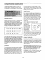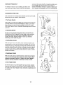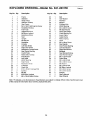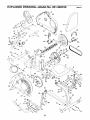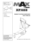
1
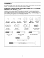
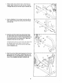
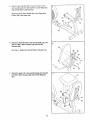
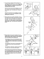
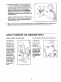
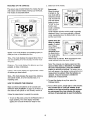
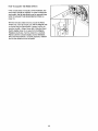
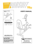
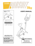
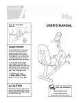
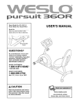
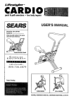
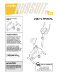
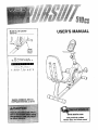
USER'S MANUAL
Model No. 831.283160
Serial No.
Serial
Number
Decal
F____.X_- R C
I ,-,_*E.
EQUIPMENT
HELPLINE!
1-800-736-6879
SEARS, ROEBUCK AND CO.,
HOFFMAN ESTATES, IL 60179
www.weslo.com
new products, prizes,
fitness tips, and much morel
TABLE OF CONTENTS
IMPORTANT PRECAUTIONS
.............................................................
BEFORE YOU BEGIN ...................................................................
ASSEMBLY ...........................................................................
HOW TO OPERATE THE EXERCISE CYCLE .................................................
MAINTENANCE AND TROUBLESHOOTING
.................................................
CONDITIONING GUIDELINES ............................................................
PART LIST ...........................................................................
EXPLODED DRAWING .................................................................
ORDERING REPLACEMENT PARTS ................................................
FULL 90 DAY WARRANTY
.......................................................
2
2
3
4
8
10
12
14
15
Back Cover
Back Cover
BEFORE YOU BEGIN
Congratulations for selecting the new WESLO ®
PURSUIT 510 CS exercise cycle. Cycling is one of
the most effective exercises for increasing cardiovascular fitness, building endurance, and toning the body.
The PURSUIT 510 CS exercise cycle offers a selection of features designed to let you enjoy this healthful
exercise in the convenience and privacy of your
home.
HELPLINE at 1-800-736-6879, Monday through
Saturday, 7 a.m. until 7 p.m. Central Time (excluding
holidays). To help us assist you, please note the product model number and serial number before calling.
The model number is 831.283160. The serial number
can be found on a decal attached to the exercise cycle
(see the front cover of this manual for the location of
the decal).
For your benefit, read this manual carefully before
you use the exercise cycle. If you have questions
after reading the manual, please call our toll-free
Before reading further, please familiarize yourself with
the parts that are labeled in the drawing below.
Water Bottle Holder*
Console
Handlebar
Resistance Knob
Backrest
FRONT
Pedal/Strap
Seat
Seat Handle
Adjustment Knob
Seat Frame
RIGHT SIDE
REAR
*No water bottle is included
3
ASSEMBLY
Assembly requires two persons. Place all parts of the exercise cycle in a cleared area and remove the packing
materials. Do not dispose of the packing materials until assembly is completed.
In addition to the included tools, assembly requires a Phillips screwdriver
wrenches
_,
_,
two adjustable
and pliers _,
Use the part drawings below to identify the small parts used in assembly. The number in parenthesis below
each drawing refers to the key number of the part, from the PART LIST on page 14. The second number refers
to the quantity needed for assembly. Note: Some small parts may have been pre-attached for shipping. If a
part is not in the parts bag, check to see if it has been pre-attached.
©H
H
M4 x 5mm
Screw (65)-2
M4 x 8mm
Screw (64)-2
M6 Nylon
Locknut (63)-4
M6 x 32mm Bolt
(62)-4
M6 Washer
(51)-8
M4 x 16mm
Screw (49)-4
M8 Nylon
Locknut (10)-4
MIO Nylon
Locknut (33)-4
M6 x 38mm Screw
(60)-8
MIO x 65mm Carriage Bolt (30)-4
M8 x 125mm Bolt (57)-2
4
M8 Split
Washer (42)-5
M8 Washer
(14)-4
M8 x 15mm Button
Screw (34)-3
M8 x 48mm Bolt (59)-2
1. While another person lifts the front of the Frame (1)
slightly, attach a Stabilizer (2) with two M10 x 65mm
Carriage Bolts (30) and two M10 Nylon Locknuts (33).
2
30
2. Attach a Stabilizer (2) to the Seat Frame (5) with two
M10 x 65ram Carriage Bolts (30) and two M10 Nylon
Locknuts (33).
33
3. Insert the end of the Seat Frame (5) into the Frame
(1). Next, firmly press the Seat Frame Bushing (20)
into the Frame. Secure the Seat Frame Bushing to the
Frame with two M4 x 5ram Screws (65). "lighten the
Adjustment Knob (9) into the Frame.
Carefully tip the exercise cycle onto its side. Attach the
two Bumpers (66) to the Frame (1) with two M4 x
8ram Screws (64). Then, tip the exercise cycle back
onto the Stabilizers (2).
q
66
64
4. Attach the Left and Right Seat Brackets (52, 53) to the
Seat Frame (5) with two M8 x 125mm Bolts (57), four
M8 Washers (14), and two M8 Nylon Locknuts (10) as
shown. Do not tighten the Nylon Locknuts yet.
5
57
14
5
14
53
5. Attacha SeatHandle(50)to theroundtubeon the
LeftSeatBracket(52)withtwoM6x 32mmBolts(62)
andtwoM6NylonLocknuts(63).
AttachtheotherSeatHandle(50)tothe RightSeat
Frame(53)in thesameway.
53
50
6. Attachthe Backrest(54)to the
Seat Brackets (52, 53)
with four M6 x 38mm Screws (60) and four M6
Washers (61).
6
See step 4. Tighten the two M8 Nylon Locknuts (10).
52
53
61
61
7. Attach the Seat (12) to the Seat Brackets (52, 53) with
four M5 x 38mm Screws (60) and four M6 Washers
(6t).
6
6O
7
12
8. The Console (16) requires three AA batteries (not
included); alkaline batteries are recommended. Insert
three batteries into the Console as shown. Make sure
that the batteries are oriented as shown by the
markings inside the Console.
8
_==-""
Batteries
Hold the Console (16) near the Handlebar (15). Insert
the console wire down through the indicated hole in
the Handlebar. Note: The console wire is longer than
shown.
Hole
Attach the Console (16) to the Handlebar (15) with
four M4 x 16ram Screws (49). Be careful to avoid
pinching the console wire.
Wire
9. While another person holds the Handlebar (15) near
the Upright (13), insert the console wire down through
the Upright. Attach the Handlebar to the Upright with
three M8 x 15mm Button Screws (34) and three M8
Split Washers (42). Be careful to avoid pinching the
console wire. Note: The console wire is longer than
shown.
9
Y
10. While another person holds the Upright (13) in the
position shown, connect the console wire to the Reed
Switch Wire (43). Next, connect the console cable to
the Lower Cable (45) in the following way:
• See drawing A. Pull up on the metal bracket on the
Lower Cable (45), and insert the tip of the console
cable (CC) into the wire clip inside the metal bracket
as shown.
10
\\\\_.. _v
Console Wi re ....._"_._
. 43..iy \
• See drawing B. Firmly pull up the console cable (CC)
and slide it into the top of the metal bracket as
shown.
1_
• See drawing C. Using pliers, squeeze the prongs on
the upper end of the metal bracket together.
Push the excess wire and cable down into the Frame
(1), and insert the Upright (13) into the Frame. Be careful to avoid pinching the wires and cables. Attach
the Upright to the Frame with two M8 x 48mm Bolts
(59), two M8 Split Washers (42), and two M8 Nylon
Locknuts (10).
7
//
lo
:onsole
IB
ii
c
. _ Metal
_
Bracket
Cable
Metalf
jf
._
CC
II
-
Bracket _ I
11. Identify the Left Pedal (24), which is marked with an
"L." Using an adjustable wrench, firmly tighten the
Left Pedal counterclockwise into the left arm of the
Crank (21). Tighten the Right Pedal (not shown) clockwise into the right arm of the Crank. Important:
Tighten both Pedals as firmly as possible. After
using the exercise cycle for one week, retighten
the Pedals. For best performance, the Pedals must
be kept tightened.
Adjust the left
and press the
the Left Pedal
shown) in the
11
58
21
24
Tab
Pedal Strap (58) to the desired position,
end of the Pedal Strap onto the tab on
(24). Adjust the right Pedal Strap (not
same way.
12. Make sure that all parts are properly tightened before you use the exercise cycle. After assembly is completed, some extra parts may be left over. Place a mat under the exercise cycle to protect the floor.
HOW TO OPERATE THE EXERCISE CYCLE
HOW TO ADJUST THE SEAT FRAME
HOW TO ADJUST THE PEDALING RESISTANCE
For effective exercise, the seat
should be in the
proper position. As
you pedal, there
should be a slight
bend in your knees
when the pedals
are in the farthest
To increase the
resistance of the
pedals, turn the
resistance knob
clockwise; to
decrease the resistance, turn the knob
counterclockwise.
Important: Stop
turning the knob
when tuming
becomes difficult,
or damage may
result
position. To adjust
the seat frame,
first loosen the
adjustment knob
on the frame, Slide
the seat frame forward or backward
to the desired
position. Retighten
the adjustment
knob.
8
\
Resists\\
Kno:Ce _
I
2. Select one of the modes:
FEATURES OF THE CONSOLE
The easy-to-use console features five modes that provide instant exercise feedback during your workouts,
The modes are described below.
Scan mode-When the power
Mode Indicators
is turned on, the
scan mode will be
selected automatically. A mode indicator will appear
below the word
"SCAN" to show
that the scan
mode is selected,
and a second
mode indicator will show which mode is currently
displayed. Note: If you have selected a different
mode, repeatedly press the Mode button to reselect the scan mode.
;gSB1
Speed, time, distance, or calorie
mode---To select
one of these
modes for continuous display,
repeatedly press
the Mode button.
The mode indicators will show
which mode is selected. Make sure there is not a
mode indicator below the word "SCAN."
Speed--This mode displays your pedaling speed, in
miles per hour or kilometers per hour.
Time--This mode displays the elapsed time. Note: If
you stop pedaling for a few seconds, the time mode
will pause.
Note: The console can display speed and distance in either miles or kilometers. To change
the unit of measurement, press the On/Reset
button for about five seconds. The letters mph or
km/h will appear in the display to show which unit of
measurement is selected. When the batteries are
replaced, it may be necessary to reselect the
desired unit of measurement.
Distance--This mode displays the distance you have
pedaled, in miles or kilometers.
Calorie--This mode displays the approximate number
of calories you have burned.
Scan--This mode displays the speed, time, distance,
and calorie modes, for a few seconds each, in a
repeating cycle.
3. To reset the display at any time, press the
On/Reset button.
HOW TO OPERATE THE CONSOLE
4. To turn off the power, simply wait for a few minutes.
The console has an "auto-off" feature. If the
pedals are not moved and the console buttons
are not pressed for a few minutes, the power
will turn off automatically to save the batteries.
Make sure there are batteries in the console (see
BATTERY REPLACEMENT on page 10). If there is a
thin sheet of clear plastic on the console, remove it.
Follow the steps below to operate the console.
1. To turn on the power, press the On/Reset button or
begin pedaling. The entire display will briefly
appear; the console will then be ready for use.
9
MAINTENANCE
AND TROUBLESHOOTING
Inspect and properly tighten all parts of the exercise
cycle regularly. Replace any worn parts immediately.
To clean the exercise cycle, use a damp cloth and a
small amount of mild detergent. Important: To avoid
damage to the console, keep liquids away from
the console and keep the console out of direct
sunlight.
Next, turn the resistance knob to the lowest setting
(see HOW TO ADJUST THE PEDALING RESISTANCE on page 8).
Open the Strap Clamp (3) and pull the end of the
Resistance Strap (11) downward slightly to increase
resistance. Close the Strap Clamp and turn the
Flywheel (37) to make sure there is not too much
resistance.
BATTERY REPLACEMENT
If the console display becomes dim, the batteries
should be replaced; most console problems are the
result of low batteries. To replace the batteries, refer
to assembly step 8 on page 7 and remove the console from the handlebar. Next, insert three batteries
into the console. Reaftach the console to the handlebar, being careful not to pinch the console wire.
HOW TO ADJUST THE RESISTANCE STRAP
If the resistance knob is turned to the highest setting
and there is not enough resistance, the resistance
strap may need to be adjusted. To adjust the resistance strap, you must first remove the left side shield.
Using an adjustable wrench, tum the Left Pedal (24)
clockwise and remove it. Next, remove the five M4 x
25ram Screws (41) and the M4 × 16ram Screw (49)
from the Left Side Shield (17). Carefully remove the
Left Side Shield.
When the resistance strap is properly adjusted, reattach the left side shield and the left pedal.
41
17
\
49
10
HOW TO ADJUST THE REED SWITCH
If the console does not display correct feedback, the
reed switch should be adjusted. In order to adjust the
reed switch, the left side shield must be removed (see
HOW TO ADJUST THE RESISTANCE STRAP on
page 10).
With the left side shield removed, locate the Reed
Switch (43). Turn the Crank (21) until the Magnet (38)
is aligned with the Reed Switch. Loosen, but do not
remove, the M4 x 16mm Screw (49). Slide the Reed
Switch slightly closer to or away from the Magnet.
Retighten the Screw. Turn the Crank for a moment.
Repeat until the console displays correct feedback.
When the Reed Switch is correctly adjusted, reattach
the left side shield and the left pedal.
11
CONDITIONING
GUIDELINES
The following guidelines will help you to plan your
exercise program. Remember that proper nutrition
and adequate rest are essential for successful results.
ber in your training zone as you exercise. For maximum fat burning, adjust the intensity of your exercise
until your heart rate is near the middle number in your
training zone as you exercise.
Aerobic Exercise
EXERCISE
If your goal is to strengthen your cardiovascular system, your exercise must be "aerobic." Aerobic exercise is activity that requires large amounts of oxygen
for prolonged periods of time. This increases the
demand on the heart to pump blood to the muscles,
and on the lungs to oxygenate the blood. For aerobic
exercise, adjust the intensity of your exercise until
your heart rate is near the highest number in your
training zone.
INTENSITY
Whether your goal is to burn fat or to strengthen your
cardiovascular system, the key to achieving the
desired results is to exercise with the proper intensity.
The proper intensity level can be found by using your
heart rate as a guide. The chart below shows recommended heart rates for fat burning, maximum fat
burning, and cardiovascular (aerobic) exercise.
165 155 145
140 130 125
145 138 130 125
118 110
103
90
20
80
40
50
60
70
To measure your
heart rate, first
exercise for at least
four minutes. Then,
stop exercising and
place two fingers
on your wrist as
shown. Take a sixsecond headbeat
count, and multiply the result by 10 to find your heart
rate. For example, if your six-second heartbeat count
is 14, your heart rate is 140 beats per minute. (A sixsecond count is used because your heart rate will
drop rapidly when you stop exercising.)
115
125 120 115 110 105 95
30
HOW TO MEASURE YOUR HEART RATE
v
To find the proper heart rate for you, first find your age
at the bottom line of the chart (ages are rounded off to
the nearest ten years). Next, find the three numbers
above your age. The three numbers are your "training
zone." The lowest number is the recommended heart
rate for fat burning; the middle number is the recommended heart rate for maximum fat burning; the highest number is the recommended heart rate for aerobic
exercise.
WORKOUT GUIDELINES
Each workout should include the following three pads:
A warm-up, consisting of 5 to 10 minutes of stretching
and light exemise. A proper warm-up increases your
body temperature, heart rate, and circulation in preparation for exercise.
Training zone exercise, consisting of 20 to 30 minutes of exercising with your heart rate in your training
zone. Note: During the first few weeks of your exercise program, do not keep your heart rate in your
training zone for longer than 20 minutes.
Fat Burning
To burn fat effectively, you must exercise at a relatively low intensity level for a sustained period of time.
During the first few minutes of exercise, your body
uses easily accessible carbohydrate calories for energy. Only after the first few minutes of exercise does
your body begin to use stored fat calories for energy.
If your goal is to burn fat, adjust the intensity of your
exercise until your heart rate is near the lowest num-
A cool-down, with 5 to 10 minutes of stretching. This
will increase the flexibility of your muscles and will
help to prevent post-exercise problems.
12
EXERCISE FREQUENCY
To maintain or improve your condition, plan three workouts each week, with at least one day of rest between
workouts. After a few months of regular exercise, you
may complete up to five workouts each week, if
desired. Remember, the key to success is make exercise a regular and enjoyable part of your everyday life.
SUGGESTED STRETCHES
The correct form for several basic stretches is shown at the right.
Move slowly as you stretch--never bounce.
1. Toe Touch Stretch
Stand with your knees bent slightly and slowly bend forward from
your hips. Allow your back and shoulders to relax as you reach
down toward your toes as far as possible. Hold for 15 counts,
then relax. Repeat 3 times. Stretches: Hamstrings, back of knees
and back.
2. Hamstring Stretch
Sit with one leg extended. Bring the sole of the opposite foot
toward you and rest it against the inner thigh of your extended
leg. Reach toward your toes as far as possible. Hold for 15
counts, then relax. Repeat 3 times for each leg. Stretches:
Hamstrings, lower back and groin.
3. Calf/Achilles Stretch
With one leg in front of the other, reach forward and place your
hands against a wall. Keep your back leg straight and your back
foot fiat on the floor. Bend your front leg, lean forward and move
your hips toward the wall. Hold for 15 counts, then relax. Repeat
3 times for each leg. To cause further stretching of the achilles
tendons, bend your back teg as well. Stretches: Calves, achilles
tendons and ankles.
4. Quadriceps Stretch
With one hand against a wall for balance, reach back and grasp
one foot with your other hand. Bring your heel as close to your
buttocks as possible. Hold for 15 counts, then relax. Repeat 3
times for each leg. Stretches: Quadriceps and hip muscles.
5. Inner Thigh Stretch
Sit with the soles of your feet together and your knees outward.
Pull your feet toward your groin area as far as possible. Hold for
15 counts, then relax. Repeat 3 times. Stretches: Quaddceps and
hip muscles.
13
I
2
EXPLODED DRAWING--Model
Key No. Qty.
No. 831.283160
Description
Key No. Qty.
R0802A
Description
1
2
1
2
Frame
Stabilizer
35
36
1
1
Belt
Axle Washer
3
4
5
6
7
8
9
10
11
12
13
14
15
16
17
18
19
20
21
22
23
24
25
26
27
28
29
30
31
32
33
34
1
4
1
3
4
4
1
5
1
1
1
4
1
1
1
1
1
1
1
1
1
1
1
1
1
2
1
4
2
2
4
3
Strap Clamp
Stabilizer Endcap
Seat Frame
M4 x 16mm Self-tapping Screw
Handlebar Endcap
Foam Grip
Adjustment Knob
M8 Nylon Locknut
Resistance Strap
Seat
Upright
M8 Washer
Handlebar
Console
Left Side Shield
Right Side Shield
Resistance Contrel/Cable
Seat Frame Bushing
Crank/Pulley
Reed Switch Clamp
MIO Washer
Left Pedal
6000Z Bearing
Right Pedal
Resistance Knob
U-bracket
Crank Nut
M10 x 65mm Carriage Bolt
Eyebolt
M6 Nut
MIO Nylon Locknut
M8 x 15mm Button Screw
37
38
39
40
41
42
43
44
45
46
47
48
49
50
51
52
53
54
55
56
57
58
59
60
61
62
63
64
65
66
#
#
1
1
1
1
5
5
1
1
1
1
1
1
8
2
1
1
1
1
4
1
2
2
2
8
8
4
4
2
2
2
1
2
Flywheel
Magnet
Flywheel Axle
6200Z Bearing
M4 x 25mm Screw
M8 Split Washer
Reed Switch/Wire
Crank Bearing Set
Lower Cable
Cable Clamp
Return Spring
Hook
M4 x 16mm Screw
Seat Handle
Inner Frame Bushing
Left Seat Bracket
Right Seat Bracket
Backrest
Seat Bracket Endcap
Seat Frame Endcap
M8 x 125mm Bolt
Pedal Strap
M8 x 48ram Bolt
M6 x 38mm Screw
M6 Washer
M6 x 32ram Bolt
M6 Nylon Locknut
M4 x 8mm Screw
M4 x 5mm Screw
Bumper
User's Manual
Allen Wrench
Note: "#" indicates a non-illustrated part. Specifications are subject to change without notice. See the back cover
of this manual for information about ordedng replacement parts.
14
EXPLODED DRAWINGmModel
No. 831.283160
ROSO2A
49
4g
58
18
34
21
,_L_34
42_
34_
59
27
26
35
44
3O
38
2
4
32
4O
12
49
62
41
17
33
4
52
3O
15
SEARS
All replacement parts are available for immediate purchase or
special order when you visit your nearest SEARS Service
Center, To request service or to order parts by telephone, call
the toll-free numbers listed at the left.
When requesting help or service, or ordering parts, please be
prepared to provide the following information:
Model No. 831.283160
• The MODEL NUMBER of the product (831.283160)
QUESTIONS?
• The NAME of the product (WESLO ®PURSUIT 510 CS
exercise cycle)
If you find that:
* you need help assembling or
operating the WESLO e PURSUIT
510 CS exercise cycle
• The KEY NUMBER and DESCRIPTION of the PART (see
the PART LIST and the EXPLODED DRAWING on pages 14
and 15)
- a part is missing
• or you need to schedule repair
service
call our toll-free HELPLINE
1-800-736-6879
Monday-Saturday, 7 am-7 pm
Central Time (excluding holidays)
REPLACEMENT
PARTS
If parts become worn and need to
be replaced, call the following tollfree number
1-800-FON-PART
(1-800-366-7278)
I
FULL 90 DAY WARRANTY
I
For 90 days from the date of purchase, if failure occurs due to defect in material or workmanship in this
SEARS BIKE EXERCISER, contact the nearest SEARS Service Center throughout the United States
and SEARS will repair or replace the BIKE EXERCISER, free of charge.
This warranty does not apply when the BIKE EXERCISER is used commercially or for rental purposes,
This warranty gives you specific legal rights, and you may also have other rights which vary from state
to state.
SEARS, ROEBUCK AND CO., DEPT. 817WA, HOFFMAN ESTATES, IL 60179
Part No. 190058 R0802A
Printed in China © 2002 Sears, Roebuck and Co.