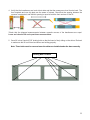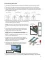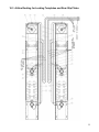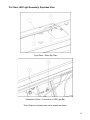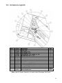
1
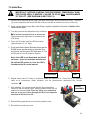
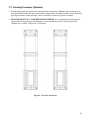
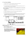
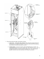
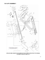
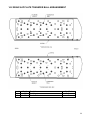
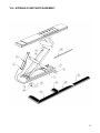
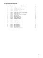
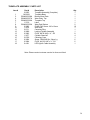
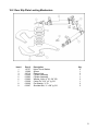
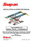
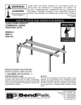
INSTALLATION and OPERATION MANUAL 10K SCISSOR LIFT MODEL: 4810605_(AF, AFM, AFX, AFMX, LL, XLL) READ THIS INSTRUCTION MANUAL THOROUGHLY BEFORE INSTALLING, OPERATING, SERVICING OR MAINTAINING THE LIFT. SAVE THIS MANUAL. 309 EXCHANGE AVENUE, CONWAY, ARKANSAS, 72032 TEL: 501-450-1500 FAX: 501-450-1585 JUL 2013 REV. - 6-3527 Table of Contents 1.0 IMPORTANT SAFETY INSTRUCTIONS ........................................................................... 4 2.0 SAFETY WARNING DECALS ........................................................................................... 6 3.0 SPECIFICATIONS ............................................................................................................. 7 4.0 CONTENTS........................................................................................................................ 8 5.0 TOOLS REQUIRED FOR INSTALL .................................................................................. 8 6.0 INSTALLATION OVERVIEW ............................................................................................. 9 7.0 INSTALLATION INSTRUCTIONS ....................................................................................10 7.1 Flushmount Bay Layout ........................................................................................... 11 7.2 Surfacemount Bay Layout........................................................................................ 12 7.3 Baseframe Location .................................................................................................. 13 7.4 Unpacking the Lift ..................................................................................................... 14 7.5 Hydraulic Connections ............................................................................................. 15 7.6 Air Safety and Auxiliary Air Connection ................................................................. 16 7.7 Electrical Connection ............................................................................................... 18 7.8 Initial Run................................................................................................................... 20 7.9 Level and Support ..................................................................................................... 21 7.10 Anchoring Procedure ............................................................................................. 23 7.11 Grouting Procedure (Optional) .............................................................................. 24 8.0 ACCESSORY INSTALLATION ........................................................................................25 8.1 Line Cover Installation............................................................................................. 27 9.0 LOCKING FRONT TURNPLATES & REAR SLIP PLATES (OPTIONAL) ...............28 9.1 Installation of Front Turnplates .............................................................................. 28 9.2 Console Connections for Locking & Lights ........................................................... 29 10.0 FINAL PROCEDURES ...................................................................................................31 10.1 Check of Assembled Lift ........................................................................................ 31 10.2 Operation Test with Vehicle ................................................................................... 31 11.0 LIFT OPERATION ..........................................................................................................32 11.1 Raising the Lift ........................................................................................................ 32 11.2 Lowering the Lift ..................................................................................................... 32 12.0 RECOMMENDED MAINTENANCE ................................................................................33 12.1 Kicker Greasing Procedure .................................................................................... 34 12.2 Checking Oil Level for Air Lubricator.................................................................... 34 12.3 Maintenance of Turnplate & Slip Plate Locking System (Opt.) .......................... 35 12.4 Adjustment of Safety Locks ................................................................................... 36 12.5 Lock Out and Tag Out Instructions ....................................................................... 37 12.6 Isolation and Verification Procedure:.................................................................... 38 12.7 Emergency Operation ............................................................................................. 39 12.8 Maintenance Schedule ........................................................................................... 41 13.0 TROUBLE SHOOTING ...................................................................................................42 14.0 LIFT ASSEMBLY ............................................................................................................43 14.1 Lift Parts List ........................................................................................................... 44 14.2 REAR SLIP PLATE TRANSFER BALL ARRANGEMENT ...................................... 46 15.0 HYDRAULIC/AIR PARTS ASSEMBLY .....................................................................47 15.1 Hydraulic/Air Parts List .......................................................................................... 48 16.0 Accessory assembly .....................................................................................................49 16.1 Front Turnplate ...................................................................................................... 49 16.2 Rear Slip Plate Locking Mechanism ..................................................................... 51 2 16.3 Airline Routing for Locking Turnplates and Rear Slip Plates ............................ 52 16.4 Rear LED Light Assembly: Exploded View .......................................................... 54 16.5 Air Switch for Light Kit ......................................................................................... 56 17.0 CONSOLE ASSEMBLY ..................................................................................................57 17.1 Console Parts List .................................................................................................. 58 17.2 Console Pneumatic / Filtering System .................................................................. 59 17.3 Console: Pneumatic & Filtering System Locking & Light System (Optional) ....................................................................... 60 17.4 Console Labeling .................................................................................................... 61 18.0 POWER PACK ASSEMBLY ...........................................................................................62 19.0 AVAILABLE ACCESSORIES .........................................................................................65 3 1.0 IMPORTANT SAFETY INSTRUCTIONS When using this lift, basic safety precautions should always be followed, including the following: 1. Only trained and authorized personnel should operate the lift or rolling jacks. Do not allow customers or bystanders to operate the lift or be in the shop area while lift is in use. 2. Read all instructions in this manual and on the lift thoroughly before installing, operating, servicing or maintaining the lift. Thoroughly train all employees in the use and care of lift and rolling jacks. 3. Inspect the lift DAILY. Do not operate if it malfunctions or problems have been encountered. 4. Ensure no one is standing in front or behind the lift while vehicle is being driven onto, or backed off the lift. 5. Before driving vehicle on, make sure lift is in the fully down position. 6. Before removing vehicle from the lift, make sure lift is in the fully down position and ensure that all tools have been removed from the deck surfaces. 7. Always raise the lift off safety locks before lowering. 8. Do not allow rear tires or portion of the vehicle to interfere with approach ramp. 9. Be sure front wheel stops are always installed on the lift. 10. Never allow front wheels to strike the front wheel stops. 11. Always use wheel chocks to keep the vehicle from rolling freely on the runways. Wheel chocks should be used at front and back of the same wheel. 12. Never attempt to overload the lift. The manufacturer’s rated capacity is shown on the identification label on side of the deck. Do not override the operating controls or safety devices. 13. Do not permit employees or customers on lift when it is either being raised or lowered. 14. Never raise a vehicle with passengers inside. 15. Always stand clear of lift when raising or lowering and observe "Pinch Points" warning. 16. CAUTION! Never work under the lift unless mechanical safety locks are engaged. 17. Always use Personal Protective Equipment (PPE) when installing or servicing the lift. 18. Always keep the lift area free of obstruction and debris. Grease and oil spills should always be cleaned up immediately. 19. Always chock vehicle wheels before raising or lowering the lift. 20. Before lowering check the area for any obstructions including people. 21. To protect against risk of fire, do not operate the lift in the vicinity of open containers of flammable liquids. 22. Adequate ventilation should be provided when working on internal combustion engines. 23. Never open hydraulic lines under pressure. 24. Do not raise or lower the lift with the vehicle on the Jackbeam. 25. For Jackbeam Safety Instructions, see Jackbeam Installation, Operation Manual. 4 READ AND SAVE THESE INSTRUCTIONS Installation shall be performed in accordance with ANSO/ALI ALIS, Safety Requirements for Installation and Service of Automotive Lifts. For additional safety instructions regarding lifting, lift types, warning labels, preparing to lift, vehicle spotting, vehicle lifting, maintaining load stability, emergency procedures, vehicle lowering, lift limitations, lift maintenance, good shop practices, installation, operator training and owner/employer responsibilities, please refer to “Lifting It Right” (ALI/SM) and “Safety Tips” (ALI/ST). For additional instruction on general requirements for lift operation, please refer to “Automotive LiftSafety Requirements For Operation, Inspection and Maintenance” (ANSI/ALI ALOIM). ATTENTION! This lift is intended for indoor installation only. It is prohibited to install this product outdoors. Operating environment temperature range should be 41 – 104 °F (5 – 40 °C). Failure to adhere will result in desertification, loss of warranty, and possible damage to the equipment. 5 2.0 SAFETY WARNING DECALS Be sure the operator is aware and understands all safety warning labels and follows them accordingly. 6 3.0 SPECIFICATIONS Maximum Capacity: 10 000 lbs 4536 kg 92-1/2 -94-1/2 Inches 2350-2400 mm 172” W/B 265-3/8 Inches 6741mm 155” W/B 255-3/8 Inches 6486mm Maximum Raised Height: 72 Inches 1829 mm Minimum Lowered Height: 9 Inches 229 mm Runway Width 26 Inches 660 mm Overall Width (min-max): Overall Length: Lifting Time (approx.): 85 seconds at max. capacity Power Requirements: 230V, 1 Ph, 60 Hz, 18A Air Supply requirements: Pneumatic Filtration Oil Type: Hydraulic Oil Capacity: Hydraulic Oil Type: Shipping Weight: 90 to 120 PSI Snap-On #IM6 or Equivalent Tank size: 4.0 gal Lift uses: 3.0 gal ISO 32 (10 weight) hydraulic oil 4724 lbs 2143 kg Figure 1 Lift Dimensions 7 4.0 CONTENTS The complete lift is contained in two (2) packages: 1. The main structural components are pre-assembled and packaged on top of each other. 2. The remaining parts are packed in a console/accessory box. Refer to the packing slip inside for a list of contents. Components include: 1pc. – Left Side Main Frame Assembly: Runway, Scissors and Base Frame 1pc. – Right Side Main Frame Assembly: Runway, Scissors and Base Frame 1pc. – Console and accessory box. (See accessory box list for contents) 1pc. – Grout container 1pc. – Customer care kit including manuals 5.0 TOOLS REQUIRED FOR INSTALL Hammer Drill or similar, 1/4” and 1/2” Concrete Drill Bits 4’ Level SAE Wrenches and Sockets Hammer Pry Bar – 5’ Long Chalk Line Tape Measure Side Cutters Screw Drivers Funnel Utility Knife Torque Wrench Recommended: Laser Leveler Plumb Bob Impact Gun Boom and/or Engine Hoist 8’ Sling Engine Crane Note: Apply LOCTITE #242 on required fasteners where symbol is shown. If fasteners are removed reapply LOCTITE before re-installing. 8 6.0 INSTALLATION OVERVIEW This is the order in which this installation is to take place: 1. Layout the Bay 2. Unpacking of Lift 3. Inspect Lift 4. Connect Air Lines 5. Connect Hydraulic Lines 6. Connect Electrical 7. Temporary shimming under Kicker area. IMPORTANT!! 8. Initial Run of Lift 9. Level, Shim & Anchor 10. Install Accessories 11. Final Check 12. Clean 13. Train customer on operation of Lift IMPORTANT: Shop air must be connected to the inlet port of the FRL unit on the console in order for lift to operate. 9 7.0 INSTALLATION INSTRUCTIONS When the lift arrives on site, please read the Installation Manual completely. Check the contents to make sure no parts are missing before starting installation. Gather all of the tools listed and make sure that the instructions are fully understood before commencing with the installation. IMPORTANT: It is the user’s responsibility to provide a satisfactory installation area for the lift. Lifts should only be installed on a level concrete floor with a minimum thickness of four and a quarter inches (4¼”) or 108 mm. Concrete must have a minimum strength of 3000 PSI or 21 MPa and should be aged thirty (30) days prior to installation. Please consult the architect, contractor or engineer if doubt exists as to the strength and feasibility of the floor to enable proper lift installation and operation. IMPORTANT: It is the user’s responsibility to provide all wiring for electrical hook-up prior to installation and to ensure that the electrical installation conforms to local building codes. Where required, it is the user’s responsibility to provide an electrical isolation switch located in close proximity to the lift that will enable emergency stop capability and isolate electrical power from the lift for any servicing requirements. WARNING: The floor surface must be inspected and the below requirements must be met. NO Drains. NO Depressions. NO Holes or Pits. In shaded area around lift If more than ¼” depression in the kicker area (10” span), this area must be filled and leveled. 10 7.1 Flushmount Bay Layout Note: Leave any additional room for any desired aisle or work area. Recommended clearance around the lift is three (3) feet. Ensure clearance conforms to local building and fire codes. Recommended overhead clearance is a minimum twelve (12) foot ceiling providing 6 feet for the maximum lift height and 6 feet for the supported vehicle. For vehicles taller than 6 feet it is recommended that the user provides additional overhead clearance or a shut off mechanism to stop the lift from raising the vehicle too high. Please contact customer service for latest installation diagram as it may change without notice. Figure 2 - Typical Bay Layout (Flush Mount) 11 7.2 Surfacemount Bay Layout Note: Leave any additional room for any desired aisle or work area. Recommended clearance around the lift is three (3) feet. Ensure clearance conforms to local building and fire codes. Recommended overhead clearance is a minimum twelve (12) foot ceiling providing 6 feet for the maximum lift height and 6 feet for the supported vehicle. For vehicles taller than 6 feet it is recommended that the user provides additional overhead clearance or a shut off mechanism to stop the lift from raising the vehicle too high. Figure 3 - Typical Bay Layout (Surface Mount) 12 7.3 Baseframe Location IMPORTANT: DO NOT CUT THE SHIPPING STRAPS HOLDING EACH SCISSOR ASSEMBLY TOGETHER UNTIL INSTRUCTED TO DO SO. 1. With reference to Figure 3, the installer should locate the most suitable location in the shop for the lift. 2. Snap a chalk line for the centerline of the lift ensuring that it matches the centerline of the bay door. * See Section 6.0 Installation Instructions for the floor surface requirements. 3. Measure and snap two (2) parallel chalk lines on either side the centerline for the inside edges of the baseframes. Refer to Figure 4 for the dimensions necessary to provide the desired width between the two runways. A distance of 36” between the baseframes will provide the standard width of 38” between the inside of the runways. This can go to a maximum of 38" to provide 40” between insides of runway. 4. Measure and snap a chalk line parallel to the shop door for the front of the baseframes, a minimum distance of 231-1/8” (178”W/B) / 221-1/8” (155”W/B) is recommended. 5. Before proceeding, ensure that once the runways are installed adequate workspace will remain in front of the lift. Figure 4: Baseframe Locations Refer to the minimum requirements listed in the installation and operation manual of any alignment equipment as needed. 13 7.4 Unpacking the Lift 1. Unpack the console and place it in the desired location at the rear of the lift. The console can be placed on either the left or right hand side of the lift. The console must be located so the operator is always facing the lift. 2. Unpack the runways and lay each baseframe along the chalk lines. Do not remove the individual strapping on the runways until they have been positioned on the chalk lines. 3. Position the baseframes on chalk lines, and ensure that the runways are parallel. Ensure that both the inside dimensions (front and back) of the baseframes as well as the diagonal distances are equal. 4. Remove the remaining packing straps, and remove the hydraulic hoses and polytubes from under the runway. Hoses are located under the rear portion of the runway and are factory pre-installed. 5. Inspect lift for damage or any irregularities. If any are found, please contact customer service before proceeding. Note: Do not pull excessively on the hoses as it may strain the connections to the baseframes. Center Line Jackbeam Rail Rear Turnplate Front Chalk Line Ensure that the turnplate pockets are at the front, and that Jack Beam rails for each runway face each other. Ensure there are no holes, depressions, or drains inside the installation area. See Section 6.0 for requirements. 14 7.5 Hydraulic Connections 1. Open the rear access covers of the console. 2. Unravel all hoses and air lines from each runway and connect the hydraulic lines as shown in Figure 6. Always make sure that the connections are clean to avoid contaminating the hydraulic system. Do not kink hydraulic hoses or air lines. Do not remove hydraulic fittings while under pressure.. 3. Connect the cylinder hoses (2-2177) to the pump manifold. Figure 6 - Air Safety, Auxiliary Air and Hydraulic Connections 15 7.6 Air Safety and Auxiliary Air Connection WARNING! WEAR SAFETY GOGGLES AND PRACTICE CAUTION WHILE WORKING WITH COMPRESSED AIR. 1. Uncoil the ¼” polytube under each deck that is connected to the air release cylinder. Route this line to the ‘y’ connector in the console. 2. Locate the FRL. The hardware is preassembled on the FRL, remove the two nuts ensuring the screws do not fall. 3. Assemble the FRL unit to the side of the console with the hardware provided on the FRL unit. Orient with supply port to the rear of the console and 90 fitting lined up with the hole in the side of the console. 4. On the inside of the console, assemble the nuts but leave loose, engaging 2 threads. 5. Rotate the FRL such that the 90 fitting passes through the hole. Secure the T-fitting inside the console to the 90 fitting with a wrench. 6. Tighten the nuts to secure the FRL 7. The 3/8” polytube for the auxiliary air connections is coiled under the right side runway. Route this hose to the console and connect it to the tee fitting inside the console. 8. A 3/8” NPT fitting (not supplied), is needed to connect shop air supply to the Air Filter / Regulator/ Lubricator Unit. Connect air line to the FRL unit located on the outside of the console. IMPORTANT: Shop air must be connected to the inlet port at the FRL unit on the console, in order for lift to operate. Attach FRL unit to the side of the console with hardware provided Union “Y” for 1/4” polytube Customer to supply 3/8” connector for airline Secure the T-fitting to the 90○ fitting on the FRL unit (3/8” air connection 16 WARNING! REPLENISH THE LUBRICANT AFTER RELEASING THE INLET PRESSURE. LUBRICATION CANNOT TAKE PLACE UNDER A PRESSURIZED CONDITION 9. Unscrew the lubricator bowl by turning it in a counter-clockwise direction 10. Fill the lubricator bowl using Snap-On Air Motor Oil #IM6 or equivalent. Oil supply to the lubricator should be less than the upper limit of the oil level The console is equipped with an Air Filter / Lubricator / and Regulator to ensure clean air supply is provided to the safety release cylinders, jackbeams and any other air tools connected to the lift. The air regulator should be set between 90-120 psi. IMPORTANT! OIL OTHER THAN ABOVE MAY CAUSE DAMAGE AND DRIPPING FAILURE Sight Dome Assembly Lubricator Bowl 11. Screw in the lubricator bowl again 12. Slowly pressurize the system. Check the sight dome assembly and verify that oil drips. Note: The regulator has been pre-set to operate at 90 psi. Note: The sight dome assembly has been pre-set to provide 3-5 drips per minute 13. Press up button to raise lift off mechanical safety locks. While holding the air safety release button, press the down button and lower the lift completely to the ground. UP Button DOWN Button Air Safety Release Button 14. Check the air system for any leaks. 17 7.7 Electrical Connection DANGER! ENSURE THAT ELECTRICAL CONNECTIONS ARE COMPLETED BY A LICENSED ELECTRICIAN! ELECTRICAL SHOCKS CAN CAUSE SERIOUS INJURY OR EVEN DEATH. NOTE: Overload fuse does not come with single phase power unit Figure 5a - Electrical Connections 18 Figure 5b - * Optional LED Driver Box Circuit Connections 19 7.8 Initial Run IMPORTANT! BEFORE STARTING THIS PROCEDURE, TEMPORARILY SHIM THE KICKER AREA, IF NEEDED. FAILURE TO DO SO WILL CAUSE DAMAGE TO THE LIFT. (SEE DIAGRAM IN SECTION 7.0) 1. Once the main electrical power supply has been connected, remove console top cover. Remove (3) screw completely and loosen the forth until you are able to rotate the cover out of the way. 2. Using a funnel with a screen filter, add 15 liters / 4 gallons hydraulic fluid (refer to Section 3.0 for recommended type). 3. Turn the potentiometer adjustment fully clockwise. Do not use excessive force to turn screw. The potentiometer adjustment is located on the PCB board. 4. Press the UP button until the LED illuminates. (Approximately 12”-14” high) 5. Press and hold the Safety Release button and the DOWN button simultaneously to lower the lift to the ground, until the green LED light goes off. This will release air from the hydraulic system. Note: If the LED is not illuminated, the lift will not lower – press the up button and raise the lift until the LED comes on. Once the LED is illuminated, the lift can be lowered. Potentiometer LED 6. Repeat these steps 5-6 times to completely bleed the system of air. Check the lift for hydraulic leaks at all connections. When complete, turn the potentiometer adjustment fully counter clockwise. 7. After bleeding, it is recommended that the fitting assemblies located on the flow divider valve, where hydraulic hoses from lift attached be cleaned. Note: Place the fitting on a workbench and use an air gun to blow through the filter in the opposite direction to flow from the lift. Fitting Assembly 8. Reinstall fitting assemblies and connect hydraulic hoses. 9. Reinstall the console top cover. 20 7.9 Level and Support NOTICE: CORRECT LEVELING IS IMPORTANT TO ENSURE THE PROPER OPERATION OF THE LIFT. TAKE PRECAUTIONS TO ENSURE ACCURATE LEVEL READINGS WHEN PERFORMING THIS PROCEDURE. Side-to-side leveling measurements should be taken off the baseframe, and measurements should be taken on each baseframe as well as between the two baseframes. Front-to-back level measurements should be taken on the runways. 1. Press the UP button and raise the lift approximately 3-4 ft off the ground. Check the location of the baseframes compared to Figure 4, and make minor adjustments as required. 2. Level the baseframes using the 5/8” leveling bolts provided at each of the four (4) corners. Leveling Bolt 5/8”-UNC Hex Bolt (6-1670) ¾”-16 UNF Support Bolt 3. Use shims provided to support under glide block area, the kicker area of baseframe and under front hinges. See Figure 7. Note: See section 6.0 Installation Instructions for floor requirements. Figure 7 – Shimming 21 4. Verify that the baseframes are level side-to-side and that the runways are level front-to-back. The front turnplate and rear slip plate are the areas of interest. Check that the spacing between the runways is as desired, and that this spacing is equal at both the front and rear of the lift. *Check that the diagonal measurements between opposite corners of the baseframes are equal. Lower and raise the lift and repeat these measurements. 5. Once lift is level, back off 5/8” leveling bolts so that the base is firmly sitting on the shims. Recheck to make sure the lift is still level and shims are holding properly. Note: These bolts must be removed once the shims are installed under the base correctly. Leveling Bolt Locations 22 7.10 Anchoring Procedure 1. Lower the lift and measure the distance between the Jackbeam rails at front and rear of the lift. 2. Raise the lift to full height and repeat the measurements, and ensure there are no differences. 3. Using a hammer drill and a ½” concrete bit, drill through the floor at each of the six (6) anchor bolt locations on each of the base frames. Make sure that the 1/2” concrete drill bit is in good condition. Refer to Figure 9 (next page). 4. Assemble the nuts and washers on the 1/2” x 4 ½” long wedge anchor bolts supplied ensuring a minimum of six threads are visible below the nut, and hammer in the anchors leaving space for shimming. NOTE: If more than 1” of the anchor is above ground, the top of the anchor must be trimmed in order for the front cover 22795 to fit. ½” x 4 ½” Long Wedge Anchor bolts 5. Use shims provided to support around anchor position and hammer anchors until they make contact with the baseplate. 6. Torque all anchor bolts to 40 ft- lbs (54 Nm). NOTE: The ½” x 4 ½” long wedge anchor bolts supplied must have a maximum of 2 ¼” exposed above the concrete. NOTE: The wedge anchor must be a minimum of 6 1/8” away from any cracks, edges and joints. 7. Position the console in the final desired location. Refer to Figure 3. Using a hammer drill and a 1/4” concrete bit, drill and anchor the console to the floor using the Nail in Anchors located in the hardware kit. 8. Check that the 3/4" support bolts on the four (4) corners of the baseframes are adjusted to ensure that the runway is level at fully collapsed position. (9 inches). Place and Anchor Console ¾” Support Bolt 9. Clean kicker area and grease kicker using multipurpose, extreme pressure grease such as Megaplex XD5, NLGI Grade 2 or equivalent. Refer to Maintenance Section 10.1 for procedure. 23 7.11 Grouting Procedure (Optional) 1. Pour grouting under the load area of each base frame as shown in Figure 9. Ensure that grout is evenly distributed under the frame and finish the edges with a 45 degree chamfer. Refer to specific grouting instructions on the package. Leave a drain area to allow any liquids to escape. 2. GROUTING MUST FULLY CURE BEFORE PROCEEDING. Do not operate the lift while grout is curing. Refer to instructions on the package for recommended cure times. [Non-Shrink Grout (3000psi min. in 24hrs, 7000psi min. in 30 days)] Figure 9 - Grouting Locations 24 8.0 ACCESSORY INSTALLATION 1. Install the front runway stops located in the accessory box using the ½” hex bolts, washers, lock washers, and hex nuts located in the hardware kit. Hex Nut Hex Bolt Flat Washer Lock Washer The runway stops are designed as a secondary means to restrain a vehicle from inadvertently rolling off the runways. Property damage and physical injuries may occur if this warning is not adhered to. 2. Install the mounting bracket and then the rear approach ramps using the Approach Ramp Pins located in the accessory box, and the hex head bolts, flat washers, lock washers, hex nuts and cotter pins located in the hardware kit. 3. Install Jackbeams with reference to the Jackbeam user manual. 25 4. Position the moveable workstep in the desired location. There are slots along the span of each runway where the workstep can be mounted. When not in use, the workstep can be stored under the front section of the runway. WARNING!! ENSURE THE WORKSTEP IS FULLY ENGAGED PRIOR TO USE. IF MORE THAN ONE WORKSTEP IS IN USE, DO NOT TRY TO STEP ACROSS OR JUMP FROM ONE STEP TO ANOTHER. NEVER USE THE WORKSTEP WHILE THE LIFT IS IN OPERATION. SERIOUS INJURY COULD RESULT FROM IMPROPER USAGE OF THE WORKSTEPS. WARNING! WORKSTEP MAXIMUM CAPACITY IS 250 LBS. WARNING! FOR FLUSHMOUNT INSTALLATIONS ENSURE WORKSTEP IS REMOVED BEFORE RAISING OR LOWERING THE LIFT. 26 8.1 Line Cover Installation 1. Install line covers once console is installed and hydraulic lines are routed. 2. Position line cover “C” behind the right baseframe as shown. 3. Cut 11-3/8” off length of line cover “B” and position it behind the left baseframe as shown. Do not discard the cut piece as it will be used in step 4. Note: It is important to create square cuts. The use of a sliding miter saw or a simple miter box is recommended. 4. Position the line covers “A” between line cover “C” & “B” and mark where they overlap. Cut each to fit. 5. Using the remaining piece of Line cover “B” from step 2, place as shown below. 6. Position line covers “D” to the console. Cut if required. 7. The number along each side of the line covers represents the quantity of fasteners required to secure them in place. Using a 1/4” concrete drill bit, drill holes as required and install the supplied 1/4” x 1” long nail in anchors (6-0141). Note: Tapcon or equivalent concrete screws can be used as an option for future removal. Optional: To locate the consoles on left side of lift, the setup is mirrored with the following changes to the above installation steps: Step 3 – use line cover A instead of B. Step 4 – use (2) of line cover B. Step 5 – use remainder of line cover A from step 3. Note: If baseframe is shimmed to a point where the line cover does not sit flush due to interference with hoses, the line cover can be heated with a heat gun and then placed over the hoses for a cleaner look. 27 9.0 LOCKING FRONT TURNPLATES & REAR SLIP PLATES (OPTIONAL) 9.1 Installation of Front Turnplates Avoid inserting fingers in the front alignment pan cut-out, if position of the turnplate assembly exposes such openings. Ensure that air supply to the lift is turned off and no person is operating on the console during maintenance of clamping elements of the locking system. During normal use, the front turnplates and rear slip plates may move rapidly, when locking system is activated. This creates pinch points for your fingers or hands. Keep hands clear of these pinch points when lift air supply is connected. No person shall operate console while maintenance or inspection of the slip plates is in process. 1. Lower lift to a comfort height. 2. Place each front turnplate assembly, one by one, on the front alignment pan on runway. Moving handles of the turn tables should be oriented to the outside of lift [Fig.1]. 28 Ensure that the locking system components on the bottom of the turnplate (air cylinder, fittings, and plastic clamping parts) are not hit against the runway during placement. 3. Verify that the turnplate assembly is completely seated in the front alignment pan. Gently slide each turnplate in the alignment pan, left and right, to verify that they can be positioned for different car widths. Do not hit plastic locking ring [Fig.2] forcefully against the edges of the cutout in the front alignment pan. 4. Connect free ends of front air lines to the turnplate locking cylinder: blue air line to the cylinder port marked with a blue dot and red air line to the cylinder port marked with a red dot [Fig.2]. 5. Plug the blue ends of the electrical connector on the turnplate light cord into the electrical connector on the cable at the front [Fig.2]. *Note: Objects in pictures may not be exactly as shown. 9.2 Console Connections for Locking & Lights Locking & Light System 1. Connect the (2) red & blue polytubes from lift to corresponding “y” fitting in the console (see Detail C). 2. Connect the 4mm polytube labeled “Return” to pushlock fitting on the LED driver box. Connect the other 4mm polytube labeled “Supply” to the pushlock “Tee” w/ reducer (see Detail “A”) 3. Connect the red & blue electrical connectors from lift to corresponding red & blue electrical connectors from the LED driver box (see Detail B). 29 1. Once all connections are made, test system as follows: a. Light System – Lift must be fully collapsed. Start raising lift, at approximately 30” from the ground, the lights will illuminate. If not, please check that the 4mm polytube connections are correct as they may be reversed. b. Locking System – On front of console, switch the Slip Plate lever to “Unlock”. All locking plates should be free to move, please verify. Now switch the lever to “Lock”, all locking plates should be centered and locked, please verify. If not, check that all polytube connections are correct and there is 90-120 psi of air pressure. 30 10.0 FINAL PROCEDURES 10.1 Check of Assembled Lift 1. Final dimension check after anchoring. ____ 2. Check for air and hydraulic leaks. ____ 3. Re-check level of decks, front to rear, side to side. ____ 4. Check all fasteners, tighten if necessary. ____ 5. Check torque of anchor bolts (Sect. 7.10) ____ 6. Operate lift to full stroke then lower to ground while checking for proper functionality. Ensure Safety Release is operational. 7. Ensure Customer Care Kit is complete and given to operator. ____ ____ a. Operation Manual ____ b. ANSI / ALI Lift It Right Manual ____ c. ANSI / ALI Safety Tip Card ____ d. ANSI / ALI ALIS Safety Requirements for Installation ____ and Service of Automotive Lifts e. ANSI / ALI Quick Reference Guide ____ 8. Ensure Oil has been added to the Filter / Regulator / Lubricator (Sect. 7.6) ____ 9. Train end user on operation of lift. ____ 10.2 Operation Test with Vehicle 1. Lower lift to the ground. (Make sure Green Light is OFF) ____ 2. Drive vehicle on to lift. ____ 3. Raise the lift, and lower onto 3-4 different locking positions until the full lifting height is reached. Check that all locks are working correctly. ____ 4. Check lowering speed and smooth decent rate. ____ 5. Lower lift to the ground and drive vehicle off lift. ____ If any problems occur during the final checkout or operation of the lift please contact customer service at 1-800-225-5786 31 11.0 LIFT OPERATION 11.1 Raising the Lift 1. If the lift is equipped with sliding Jack Beam(s), be sure that the Beam(s) are positioned at the front or mid travel of the lift, fully down, and with the risers removed and stored. Never store Jack Beams at the rear of the lift. 2. Ensure that the lift is fully lowered before attempting to load or unload a vehicle. 3. Ensure that locking pins are in the front turnplates and rear slip plates before driving a vehicle onto the lift. 4. Position the vehicle on the lift ensuring the resulting load on the deck is distributed as evenly as possible. Under no circumstances should a vehicle be lifted if the weight distribution is unbalanced by more than 10% on either side. NOTE: THE VEHICLE IS POSITIONED CORRECTLY WHEN THE DISTANCE FROM THE CENTER OF THE TIRES TO THE INSIDE EDGE OF THE RUNWAYS IS EQUAL ON BOTH RUNWAYS, FOR BOTH THE FRONT AND REAR TIRES. 5. Chock the vehicle using the wheel chocks provided. 6. Check that there are no obstructions above the lift that could damage the lift or vehicles. 7. Raise the lift by pressing the up button on the control console. Raise the lift until the green light is illuminated. (The lift can only be lowered if the green light is on). 8. Lower the lift onto a mechanical safety lock by pressing the down button. Continue to hold the DOWN button until the green light goes off. (Approx. 3-10 seconds) 9. Do not raise or lower the lift with the vehicle on the Jack Beam. WARNING! NEVER WORK UNDER A VEHICLE OR THE LIFT UNLESS IT IS POSITIONED ON BOTH MECHANICAL SAFETIES! 11.2 Lowering the Lift NOTE: The lift can only be lowered if the green light is on. If the light is not on, raise the lift until the light turns on. If the lift is at its maximum lifting height, a change in tone may be noticed while raising the lift (This change is the pump working at max relief pressure). Only press the up button until the green light comes on. 1. Lower the vehicle from the Jack beams and remove lift pads and store. If removing the vehicle from the lift, slide Jack Beams to their appropriate position, at the front or mid section of the lift. Check that there are no other obstructions under the lift or vehicle. 2. Raise the lift by pressing the up button until both runways are clear of their mechanical safety locks. 3. Press the air safety release button to release the mechanical safeties. 4. While holding the air safety release button, press the down button and lower the lift to the completely collapsed position. Continue to hold the DOWN button until the green light goes off. 5. Remove wheel chocks and ensure that locking pins are in the front turnplates and rear slip plates before driving a vehicle off the lift. 6. Be certain that the lift is completely lowered before removing the vehicle from the lift. 7. Do not raise or lower the lift with the vehicle on the Jack Beam. ATTENTION! THE OPERATOR MUST ALWAYS KEEP THEIR ATTENTION ON THE OPERATION OF THE LIFT WHILE RAISING OR LOWERING. IF AN OBSTRUCTION IS SEEN, RELEASE BOTH THE AIR SAFETY RELEASE BUTTON AND THE DOWN BUTTON TO STOP THE LIFT. 32 12.0 RECOMMENDED MAINTENANCE The following maintenance schedule is recommended for ensuring the operation of the lift. A record of maintenance performed should be maintained and any items that resulted in additional service should be noted. Schedule Maintenance Required Check that the upper and lower glide tracks are clean and free of debris. This area should be checked before raising or lowering the lift. Inspect the operation of the lift by raising and lowering the lift fully. Daily Check for the proper engagement and release of mechanical safety locks. If bolts are removed for maintenance re-apply LOCTITE #242 before re-assembly Check hydraulic lines for leaks and fraying. Frayed hoses must be replaced immediately. Check the fluid level in the reservoir with the lift fully lowered. Top up reservoir with ISO 32 (10 weight) hydraulic oil as needed. Weekly Check Oil Level in Air Line Lubricator and refill if required (See 11.2) Check anchor bolts for tightness. Torque to 40 ft-lbs if needed. Inspect the electrical and mechanical operation of all switches. Monthly Clean kicker plate and re-grease. See Section 11.1 for procedure and grease requirements. (See Figure 7 for kicker area). Inspect runway stop fasteners monthly. Yearly 5 Year Fitting assembly on Flow Divider to be removed and cleaned. See Section 7.8, step 7 for procedure. Change the hydraulic fluid every five years. Use only ISO 32 (10 weight) hydraulic oil. NOTE: FAILURE TO FOLLOW RECOMMENDATION MAY AFFECT WARRANTY OF LIFT 33 12.1 Kicker Greasing Procedure 1. Clean both the kicker and the kicker area on the baseframe. 2. Grease kicker using multipurpose, extreme pressure grease such as Megaplex XD5, NLGI Grade 2 or equivalent. 3. Locations to be cleaned and greased are as shown below: 12.2 Checking Oil Level for Air Lubricator The Air Lubricator is located on the outside of the console to allow for easy monitoring of the oil level. If oil level is low, refill the lubricator bowl using one of the following methods: Method 1 – Can be done under pressure. 1. Unscrew the lubrication plug assembly 2. Refill the bowl using Snap-On Air Oil #IM6 or equivalent 3. Screw in the lubrication plug assembly 4. Check the number of oil drops again. This does not usually need to be adjusted Method 2 – Cannot be done under pressure 1. Release inlet pressure from system 2. Unscrew lubricator bowl 3. Fill the lubricator bowl using Snap-On Air Oil #IM-6 4. Screw in lubricator bowl 5. Slowly pressurize system 6. Check the number of oil drops again. This does not usually need to be adjusted Lubrication Plug Assembly NOTE: Failure to maintain oil level in lubricator will void warranty on all pneumatic components. Lubricator Bowl 34 12.3 Maintenance of Turnplate & Slip Plate Locking System (Opt.) 1. Observe locking mechanisms with every lift rise for air line connection integrity. Also ensure that no foreign objects were trapped in the clamping components. 2. Once a week inspect the mating conical surfaces of the front turnplate locking mechanism [Fig.3]. If necessary, blow with compressed air or wipe with a clean cloth any road dust, salt or other contaminants, including liquids. Greasing of these surfaces is not required and not recommended. 3. After extended use, it may be required that some components of the front turnplate will need replacement, due to normal wear. Please ensure to re-apply Loctite where needed, as detailed in the exploded view of the front turnplate [Fig.4]. 4. Once a week inspect locking mechanisms of the rear slip plates. Ensure that clamping jaws are securely attached to cylinder clevises and to pivot pins, and that mounting hardware and air fittings are properly fastened. 5. If replacement of rear clamping components becomes necessary after extended use, re-apply Loctite to the threads of the rear cylinder shoulder bolts. Exploded view of one set of the 4 rear clamps on the lift is shown in Section 17.2. ** Re-apply Loctite to bolt threads if removing bolts. Tighten shoulder bolts completely in their sockets 35 12.4 Adjustment of Safety Locks 1. Loosen all the bolts with an 9/16” open wrench 2. Raise lift the lift to its highest position 3. Center the top safety rack in between the bottom safety rack. 4. Tighten each bolt in sequence as shown in the figure below. Check the alignment after tightening each bolt. . 6. Raise the lift and then lower it down, and visually inspect to make sure the adjustment is even. If the adjustment is not even, follow each step again until safety locks touch evenly. 36 12.5 Lock Out and Tag Out Instructions IMPORTANT: This machine does not have integral devices that will isolate the electrical, pneumatic, stored and hydraulic energy source. Appropriate isolation or blocking devices must be used that have the provisions to be switched in the off position and locked in that position. ALL MAINTANANCE AND SERVICE MUST BE PERFORMED BY A QUALIFIED PERSON. ALL MAINTANANCE AND SERVICE MUST BE PERFORMED WITH THE LIFT UNLOADED. IT IS THE SHOP OWNERS RESPONSIBILITY TO ENSURE ENERGY ISOLATING DEVICES ARE: Accessible Conveniently located to facilitate the application of lockout devices during service and maintenance Located outside any hazardous area. At a convenient manipulating height (i.e. not overhead, on ladders or under machinery) Adequately labeled or marked. Identification shall include machine ID, energy type and magnitude. Capable of being locked or otherwise secured in an effective isolating position. Effective hazardous energy control procedures will protect employees during machine and equipment servicing and maintenance where the unexpected energization, start up or release of stored energy could occur and cause injury, as well as while working on or near exposed de-energized electrical conductors and parts of electrical equipment. Hazards being guard against include being caught in, being crushed by, being struck by, being thrown from, or contacting live electrical circuits/parts. In preparation for lockout, an initial survey must be made to locate and identify all energy isolating devices to be certain which switch, valve, or other energy isolating devices apply to the machine / equipment to be locked out. More than one energy source (electrical, hydraulic, pneumatic, or others) may be involved. - SHUT DOWN PROCEDURE: Notify all affected employees that a lockout or tagout system is going to be utilized and the reason for. The authorized employee shall know the type and magnitude of energy that the lift utilizes and shall understand the associated hazards. ELECTRICAL: Located at the user control panel, press the “E-STOP” button to disconnect the raise and lower functions. 37 12.6 Isolation and Verification Procedure: Table 1: ISOLATION AND VERIFICATION PROCEDURES: ENERGY TYPE AND SOURCE STORED ENERGY AND HYDRAULIC PRESSURE 3000-5000 PSI LOCKOUT LOCATION (TO BE COMPLETED BY END USER) PROCEDURE FOR LOCING OUT AND OR RELEASING ENERGIES LOWER THE LIFT TO ITS LOWEST REST POSTION. IF THE LIFT MUST BE SERVICED OR MAINTAINED IN THE RAISED POSITION, ENSURE THAT THE LIFT IS PLACED ON THE MECHANICAL LOCKS AND SUPPORTED BY SUPPLEMENTARY JACK STANDS, BLOCKED AT THE SLIDERS AND A COME ALONG SECURED BETWEEN THE SCISSORS. VERIFY PROCEDURES VERIFY THAT THE LIFT IS CONTACTING THE SUPPLEMENTARY JACK STANDS, THE BLOCKS ARE SECURLY PLACED AND THE COME ALONG IS SECURED BETWEEN THE SCISSORS. PRESS THE DOWN BUTTON ON THE CONSOLE AND VERIFY THAT THE LIFT DOES NOT LOWER. VERIFY HYDRAULIC PRESSURE HAS BEEN REMOVED BY SLOWLY OPENING THE MAIN HYDRAULIC FITTING AT THE POWER UNIT ONLY. IF FLUID IS PRESENT UNDER PRESSURE, IMMEDIATLY TIGHTEN AND REPEAT LOWER PROCESS. ENSURE THAT BOTH STRUCTURES ARE SECURELY PLACED ON THE STANDS AND BLOCKED. AT THE LIFT, PRESS THE EMERGENCY STOP BUTTON COMPLETELY TO DE-ENERGIZE THE CONTROL BUTTONS. ELECTRICAL 240VOLTS AT THE DISCONNECT PLANEL, PLACE THE DISCONNECT HANDLE IN OFF POSITION. ATTACH A MULTIPLE LOCKOUT DEVICE. LOCK AND TAG. ATEMPT TO RESTART THE SYSTEM, THE SYSTEM MUST NOT START. VISUALLY VERIFY OPEN DISCONNECTS AND LOCKING DEVICE INSTALLED. DANGER: LINE SIDE OF DISCONNECT REMAINS ENERGIZED PNEUMATIC UPTO 160PSI SLOWLY CLOSE LOCKOUT VALVE TO RELEASE AIR PRESSURE GRADUALLY. ATTACH MULTIPLE LOCKOUT DEVICE, LOCK AND TAG. DANGER: LINE SIDE OF DISCONNECT REMAINS PRESSURIZED VERIFY THE VALVE IS CLOSED AND LOCKOUT DEVICE IS PROPERLY ATTACHED. OPERATE THE PNEUMATIC SYSTEM TO ENSURE THE SYSTEM IS DE-ENERGIZED. IT MAY BE NECESSARY TO BLEED THE SYSTEM OF REMAINING COMPRESSED AIR, THIS CAN BE PERFORMED AT THE BASE OF THE WATER SEPARATOR BOWL. 38 - RETURNING TO SERVICE: Check the lift and the immediate area around the lift to ensure that nonessential items,, tools and parts are removed and that the lift components are operationally intact. Check the work area to ensure that all employees have been safely positioned or removed from the work area. Notify all employees that the lockout/tagout is going to be removed and the lift is going to restarted. Remove the lockout/tagouts in the reverse order as the installation. Verify the proper operation of the equipment. Notify affected employees that the maintenance/service is completed and the machine is ready for operation. 12.7 Emergency Operation If the lift becomes inoperative in the raised position, it is best to wait until the electrical power is restored before lowering the vehicle. However, if it’s critical to safety that the lift be lowered, the following steps should be taken. WARNING: DO NOT LOOSEN OR REMOVE HYDRAULIC CONNECTIONS OR FITTINGS UNDER PRESSURE. SERIOUS INJURY OR DEATH COULD OCCUR. NOTE: Safely performing this process requires 3 people. All personnel should stay clear of the path of the lift. All tools and other non-secured items should be removed from the surface of the ruways. 1) Survey the area surrounding the lift; remove any items and personnel from area before proceeding with this procedure. 2) Perform the appropriate lockout/tag out procedure on the electrical energy. 3) Add additional chocks to the vehicle to secure it from movement in the forward and rear direction. 4) Use a second person standing at a safe distance away from the lift to keep watch on the area, lift, vehicle and other personnel throughout the process. This person should signal the person performing the procedure to stop if necessary. 5) Use a caution tape or similar to barrier the area around the lift to avoid personnel from accidently entering the area while this process is being performed. 6) Do not proceed with this procedure if you are unfamiliar with the lift or its function. IF THE MECHANICAL LOCKS ARE NOT ENGAGED: 1) If there is air pressure in the pneumatic system; have another person press and hold the mechanical safety release button to disengage the mechanical locks. Confirm that both mechanical locks have been disengaged and will allow the lift to lower. If there is no air pressure in the pneumatic system; use a rag to raise the upper mechanical locks to sufficiently clear the lower locks on both sides. 2) Remove the 6 screws retaining the rear cover of the control console. 3) Locate the flow divider and remove the red caps on the two outer descent valves. 39 4) Slowly turn each manual override thumbscrew in the counterclockwise direction. The lift should not come down at this point. 5) Locate the descent valve on the hydraulic power unit, see Figure 30. Figure 30 – Image of descent valves 6) Locate the manual override thumbscrew (red) on the top of the descent valve, see Figure 30. 7) Verbally indicate to all those involved that the lift will now be lowered. 8) Slowly turn the manual override thumbscrew in the counterclockwise direction until the lift starts to move. 9) Keep a close eye on the movement of the lift and the position of the vehicle; turn the manual override thumbscrew clockwise if any abnormal movement is detected. 10) Once the lift is fully lowered, turn the override thumbscrew in the clockwise direction until tight. 11) If a rag was used to bypass the mechanical locks, ensure that the rag is removed after the lift has been put back into operation. 12) Once power is restored follow the lockout/tag out procedure to return the lift back into service. IF THE MECHANICAL LOCKS ARE ENGAGED: Various methods can be used to raise the lift in order to get sufficient clearance to disengage the mechanical locks. The safest method would employ temporary electrical power to the lift using a portable power generator. Any electrical connections should be done by a licensed electrician; lock out/tag out procedures should also be employed at this time. This process should only be performed by a trained professional. Contact customer service or a local service professional for further assistance. 40 12.8 Maintenance Schedule Records of all lift maintenance and operator training should be recorded in the following table. Maintenance and Training Performed Date By Notes 41 13.0 TROUBLE SHOOTING PROBLEM Motor does no turn. Motor runs but lift doesn't go up . REASON Bad fuse or circuit breaker. Incorrect voltage to motor. Incorrect wiring. Motor switch is malfunctioning Motor burned out L ow oil level Wrong rotation Lift doesn't come down. Safety doesn't disengage . Lift goes up un-level. Anchor Bolts do not stay tight Dirt in hydraulic lines *Secure vehicle on lift, and clean Check power to hydraulic lines No power to solenoids Lift not raised high enough for disengagement Air not supplied to air cylinder Air cylinder malfunctioning Flow-divider defective hydraulic lines. Check power to solenoids Press Up button for longer period of time . Check if supply line has air. Replace air cylinder. Reverse hydraulic connections Remove & inspect flow through line Relocate lift using proper drill Size. Concrete should be replaced by an appropriate concrete pad . (Consult Product Manufacturer / Supplier for further details) Clean kicker and area. Grease kicker (see Section 11.1 for Greasing Procedure) Blockage in hydraulic hose Holes are to large. Incorrect concrete floor specification. (Thickness and Strength) Noise SOLUTION Re place fuse or reset breaker. Provide proper voltage to motor. Have certified electrician check Replace motor switch. Re place motor. Fill reservoir with proper hydraulic oil. Check for oil flow & reverse electrical leads Squeaking noise during first few inches o f rise 42 14.0 LIFT ASSEMBLY REPLACE WORN, DAMAGED OR BROKEN PARTS WITH PARTS APPROVED BY THE ORIGINAL EQUIPMENT MANUFACTURER ONLY 43 14.1 Lift Parts List Note: Quantities list are for one side of lift. Opposite side is symmetrical. Item# Part # Description 1 2 3 4 5 6 7 8 9 10 11 12 14 15 16 17 18 19 20 3-0978 2-2301 2-2599 6-2899 6-3087 6-3419 1-2795 1-2791 6-0233 2-2470 1-3284 6-0816 1-3223 6-1523 1-3185 1-0757 1-3171 6-3418 4-1438 4-1439 4-1440 4-1441 4-1434 4-1435 4-1436 4-1437 1-3171 2-2111 2-2112 2-2183 1-3186 4-1171 2-2725 2-2117 1-3159 3-0905 3-0698 1-1099 1-3062 6-0267 2-2505 2-2721 2-2740 2-1733 6-0233 6-2281 1-2788 6-0340 6-2936 BASEFRAME WELDMENT BASE FRAME COVER (L) SCISSOR ASSEMBLY BUSHING, PIVOT, 1-1/2" ID, 24TH24 BUSHING 1-1/4" 1-5/8 SELF-LUBRICATING BUSHING, 26TH24 SCISSOR SPACER SCISSOR PIN SNAP RING, #5100-150 KICKER ASSEMBLY Scissor spacer 10K Flat Washer, #10 BEARING BLOCK, INNER SCREW, #10 X 1-1/2, SELF-TAP KICKER PIVOT PIN NYLON THRUST WASHER THRUST WASHER SNAP RING, #5100-163 DECK WELDMENT, LH (173") DECK WELDMENT, RH (173") DECK WELDMENT, LH (173”) – LOCKING & LIGHTS OPTION DECK WELDMENT, RH (173”) – LOCKING & LIGHTS OPTION DECK WELDMENT, LH (155") DECK WELDMENT, RH (155") DECK WELDMENT, LH (155”) – LOCKING & LIGHTS OPTION DECK WELDMENT, RH (155”) – LOCKING & LIGHTS OPTION THRUST WASHER SAFETY BAR BOTTOM (LASER CUT) SAFETY BAR, TOP (LASER CUT) SCISSOR SAFETY COVER KICKER CLEVIS PIN CYLINDER ASSEMBLY SLIDER BLOCK WHEELSTOP WELDMENT ADAPTOR PLATE APPROACH RAMP ASSEMBLY (SURFACE MOUNT) APPROACH RAMP ASSEMBLY (FLUSH MOUNT) CLEVIS PIN RAMP ROLLER Cotter Pin, 1/8" Dia. x 1" LG. REAR SLIP PLATE REAR SLIP PLATE WELDMENT – LS (LOCKING & LIGHTS) REAR SLIP PLATE WELDMENT – RS (LOCKING & LIGHTS) ROD END SNAP RING, #5100-150 PHILIPS SCREW #6 HINGE PIN CIRCLIP TRU-ARC #5100-125 HEX HEAD GR5 BOLT, 3/4-16 UNF X 1-1/2 LG 21 23 24 25 26 27 28 29 30 31 32 33 34 35 36 37 38 39 40 41 Qty. 1 2 1 2 2 2 2 2 4 1 2 5 1 5 1 4 8 2 1 1 1 1 1 1 1 1 4 2 2 1 1 1 4 1 1 1 1 2 2 2 1 1 1 1 2 4 2 4 4 44 42 43 44 45 46 47 48 49 50 51 52 54 55 57 58 59 60 61 62 63 64 65 66 67 68 70 71 72 73 80259000 1-2793 6-0058 6-0067 6-0291 6-0063 6-0059 6-0035 6-2956 6-3974 1-3762 3-0812 1-2789 2-2119 6-0666 6-0034 6-0259 6-2936 6-0426 6-0206 2-0637 6-1670 1-1887 6-0738 6-0978 2-2409 6-1134 1-1384 1-2905 HEX JAM NUT, 3/4"-NF CYLINDER RETAINER LOCK WASHER, 3/8" HEX BOLT, 3/8" NC X 1" LG Hex Bolt,1/2"-13UNC X 1 1/2 LG. Flat Washer, 1/2" Lock Washer, 1/2" NUT, 1/2-13 UNC, HEX 90 HYD ELBOW VELOCITY FUSE 4GPM TRANFER BALL BEARING PLASTIC PUCK INSERT AIR CYLINDER ASSEMBLY CYLINDER PIN WORKSTEP HEX BOLT 3/8 UNC X 1-1/4 LG, GR8 HEX NUT, 3/8" NC LOCK WASHER, 3/4 HHCS, 3/4-16 UNF X 1-1/2 LG FLAT WASHER Shoulder Bolt, 3/8" DIA. X 1" LG. LOCKING PIN ASSEMBLY HEX BOLT GR5, 5/8"-NC x 2" LG HEADED PIN FLAT WASHER 3/4" SAE Cotter Pin, 1/8" DIA. X 1 ½" LG. WEAR PLATE SELF TAPPING SCREW, #12 X 1/2" LG TUBE END COVER SAFETY LOCK SPACER 4 2 12 4 5 5 5 5 1 36 18 1 1 1 8 8 2 2 4 4 2 6 2 6 2 1 4 2 4 OPTIONS 56 TURNPLATE ASSEMBLY Contact your local sales personnel for part number and cost. 45 14.2 REAR SLIP PLATE TRANSFER BALL ARRANGEMENT Item # 1 2 Part # 1-3762 6-3974 Description Plastic Insert Transfer Ball Qty. / Deck 19 35 46 15.0 HYDRAULIC/AIR PARTS ASSEMBLY 47 15.1 Hydraulic/Air Parts List Item Part # 1 2 3 4 5 6 7 9 11 12 13 14 15 16 17 18 19 20 21 2-2717 6-3019 6-3020 6-3896 6-2956 6-3010 6-0167 6-0709 6-0170 6-1134 6-0178 6-0060 2-2795 2-2519 2-2520 2-2733 2-2735 2-2734 2-2736 6-0141 Description 3/8" Hydraulic Hose 3/8" Polytube, 480" LG 1/4" Air Hose, 350" LG Branch Tee Fitting ¼ NPT, F-F-M Velocity Fuse 90 DEG Elbow, 1/4" NPT-M, 3/8" Polytube Terminal Bolt, 3/4" 90 DEG Elbow, 1/8" NPT, 1/4" Polytube Pipe Clamp, 3/8" Self Threading Screw 1/4" Hex HD Bolt x 3/4” 1/4" SAE, Flat Washer Front Cover Baseframe, Line Cover Baseframe, Line Cover Floor Line Cover “A” Floor Line Cover “C” Floor Line Cover “B” Floor Line Cover “D” Nail-in Anchors, ¼” x 1” Lg. Qty 2 1 2 1 2 1 1 2 8 8 6 6 2 1 1 2 1 2 2 37 48 16.0 Accessory assembly 16.1 Front Turnplate 49 TURNPLATE ASSEMBLY: PARTS LIST Item # 1 2 4 5 7 8 9 10 11 12 13 14 15 16 17 18 Part # 2-2932 M2-2931 EAM0047J58A EAM0047J57A EAM0047J60A 1-3719 EAM0047J52A 6-3955 1-3678 2-2711 6-3899 6-3903 1-3677 2-2709 6-3954 6-3904 6-4101 Description Turnplate Assembly (Complete) Turnplate Base Bottom Wear Plate Wear Plate, Top Turnplate Top Label Wear Pad, Bottom FHMS, Phil Screw - M6 x 16mm Stub Shaft Centering Ring Locking Cylinder Assembly FHCS, #8-32 UNC x ¾”, SS Cylinder Stand-off Centering Cone Screw, FHMS M5-8 x 10mm Lg FHCS, #10-32 UNF x ¾”, SS LED Light & Cable Assembly Qty. 1 1 1 1 1 1 2 10 1 1 1 8 4 1 6 6 1 Note: Please contact customer service for items not listed. 50 16.2 Rear Slip Plate Locking Mechanism Item # 1 2 3 4 5 6 7 8 9 Part # 1-0757 1-3686 2-2712 6-3900 6-3883 6-3882 6-3929 6-0060 6-3907 Description Nylon Thrust Washer Spacer Retainer Jaw Cylinder Assembly Cylinder Assembly Washer, Nylon ¼” ID 5/8” OD Cotter Pin, 3/16” x 2” lg, SS Flat Washer, ¼” ID Shoulder Bolt, ¼” x 5/8” lg. SS Qty. 4 1 2 1 1 2 1 6 2 51 16.3 Airline Routing for Locking Turnplates and Rear Slip Plates 52 Airline Parts List Item Part Number Description Location From Console, on floor, on scissors, up to deck hinge From Console, on floor, on scissors, up to deck hinge 1 1-3733 Air Line, Blue, 1/4”, 35’ 2 1-3732 Air Line, Red, 1/4”, 35’ 3 1-3735 Air Line, Blue, 1/4", 7.8’ On decks, from hinge to front 2 4 1-3734 Air Line, Red, 1/4", 7.8’ On decks, from hinge to front 2 5 6-3950 Tube Clamp On decks, at front 2 6 6-2971 Fitting, Tee, 1/4" On decks 8 7 1-3736 Air Line, Red, 1/4", 3.1’ On decks, from hinge to middle 2 8 1-3737 Air Line, Blue, 1/4", 3.1’ On decks, from hinge to middle 2 9 1-3741 Air Line, Blue, 1/4", 1.1’ On decks, feeding middle clamp 2 11 1-3740 Air Line, Red, 1/4", 1.1’ On decks, feeding middle clamp 2 12 1-3738 Air Line, Red, 1/4", 8.25’ On decks, middle to rear 2 13 1-3739 Air Line, Blue, 1/4", 8.25’ On decks, middle to rear 2 14 1-3742 Air Line, Red, 1/4", 5” 15 1-3743 Air Line, Blue, 1/4", 7” Between clamp cylinders, rear and middle Between clamp cylinders, rear and middle Qty/Lift 2 2 4 4 53 16.4 Rear LED Light Assembly: Exploded View Top of Deck – Rear Slip Plate Underside of Deck – Connection of LED Light Bar *Note: Objects in pictures may not be exactly as shown. 54 REAR LED LIGHT ASSEMBLY: Parts List Item # 1 2 3 4 5 Part # 2-2721 2-2740 6-4092 6-4091 6-3936 6-3940 6-4089 6-4093 Description Rear Slip Plate Weldment, LS Rear Slip Plate Weldment, RS LED Light Bar w/ mounts & connector (Left side) LED Light Bar w/ mounts & connector (Right side) Push Retainer Adhesive Back Clamps Cable Extension Assembly (LS) Cable Extension Assembly (LS) Qty. 1 1 1 1 2 3 1 1 55 16.5 Air Switch for Light Kit Item # 1 2 3 4 5 6 7 8 9 10 11 12 13 * * Part # 2-2757 6-0295 6-0674 6-0293 6-1792 6-0062 6-0340 1-3754 1-3752 1-3771 6-3965 6-3964 6-3944 8-0378 8-0377 Description Plastic Cam Flat Washer, 5/16” Lock Washer, 5/16” Hex Head bolt, 5/16”-18UNC x 1” Lg. Shoulder Bolt, 3/8” x ½” Lg. Flat Washer, 3/8” Circlip Hinge Pin, Cam Spacer Sensor Bracket Machine screw, #8-32 x 1”lg Limit Switch w/ Roller Lever Union, ‘Y’, 5/32” (4mm) Polytube 4mm Polytube Blue 4mm Polytube Red Qty. 1 1 1 1 1 1 2 1 1 1 2 1 1 40 ft 40 ft Note: Light Kit Sensor Assembly is located under Passenger Side Deck. 56 17.0 CONSOLE ASSEMBLY 57 17.1 Console Parts List Item 1 2 4 5 6 7 8 11 12 13 14 15 16 17 18 19 20 21 22 23 24 25 26 27 28 29 30 31 32 33 34 35 36 37 38 39 40 41 42 43 44 45 46 47 48 49 50 51 52 Part # 3-0973 3-0974 2-2512 2-2513 6-2125 6-3409 6-0709 6-3406 6-3266 6-3597 6-3410 6-2126 6-3415 8-0141 6-3720 6-3580 6-2971 6-3665 1-3625 6-2128 6-2129 6-1364 6-2553 6-3684 6-2127 2-2717 6-2922 6-1055 6-1247 6-0090 2-2592 6-0804 6-0011 6-0797 6-0710 6-0713 6-2314 1-3282 6-3421 6-3422 6-0674 6-0294 6-0295 6-3423 6-3424 6-3305 6-0988 6-2481 6-1766 Description Front Side Panel Back Electrical Plate Cover Rear Cover Top Cover Printed Circuit Board Multihole, 3 holes x 7 mm 189.637 Elbow, 90 deg. Contactor Tayco P/N 3100-20 Fuse Holder 2-Pole Open Style Fuse, 1A 250V Bushing Heyco P/N 184.175 Transformer Grounding Bar 1/4" Polytube, 2 ft. PowerPack Assy. 230V/1PH/60Hz Green LED pilot lamp 1/4" Polytube Tee Pushlock Flow Divider c/w Solenoids Din Connector High Body Small Conduit Coil S8 24VDC Cartridge Valve N/C with manual override Cartridge Valve Equalize VEI DT Filter fitting 1/2 BSP #6 JIC c/w Bonded Seal Pressure SW 80 psi Filter fitting 3/8 BSP #6 JIC c/w Bonded Seal Hydraulic Hose Emergency Pushbutton Contact Air Release Button Pushbutton Flow Control Hydraulic Hose Ass’y Elbow, 90 deg. Adapter, 3/8" M NPT x 3/8" M JIC Adapter 3/8" NPT M x 3/8" Adapter 3/8" x 3/8" Polytube Terminal Bolt, 3/4" (Short) Electrical Knockout Plug Power Pack mounting spacer Screw BHCS 5/16"-18 x 1 1/2" Screw BHCS 5/16"-18 x 2 1/2" Washer, Lock 5/16" ID Nut, 5-16" - 18 UNC Hex Washer, Flat 5/16" SAE Screw Pan Sq. SEFL 8 x 1/2" Zinc Screw 10 x 3/4" Zinc Hold Down Adhesive Mount Base Decal Set, ALI/WL 200 Decal, Elec 208 - 230, 60 Hz 1PH 20A Decal, Capacity 10000lb/4550kg Qty 1 1 1 1 1 2 1 1 1 2 1 1 1 1 1 1 1 1 4 4 3 1 1 2 2 2 1 1 2 1 1 1 1 1 1 1 1 4 4 2 6 6 6 15 3 5 1 1 1 58 17.2 Console Pneumatic / Filtering System ITEM 1 2 3 4 5 6 PART # DESCRIPTION 0-1693 6-1055 6-3729 6-0015 6-0709 6-3730 Water Separator / Regulator / Lubricator Kit Control Valve Union ‘Y’, ¼” Poly 90 Elbow ¼ NPT Swl Elbow, ¼” POLY x 1/8” NPT M Swl Tee Adapter, 3/8 Poly X 3/8 Poly X ¼ NPT QTY 1 1 1 1 2 1 59 17.3 Console: Pneumatic & Filtering System Locking & Light System (Optional) Item # 1 2 3 5 6 7 9 10 11 12 13 14 15 16 Part # 6-4142 6-1055 6-3729 6-3905 6-0708 6-3977 6-3731 6-3730 6-0709 6-3729 6-3928 6-4088 6-3952 6-0015 Description Water Separator/Regulator/Lubricator Ass’y Control Valve (Safety Release) Union ‘Y’, ¼” Poly Valve Assembly (Locking Plates) Adapter, 1/8” NPT – ¼” Poly Breather – Female 1/8” NPT Reducer, 3/8” Stem x ¼” Poly Swivel Tee Adapter, ¼”NPT x 3/8” Poly Swivel Elbow, 1/8” NPT M x ¼” Poly Union ‘Y’, ¼” Poly Reducer, ¼” Stem x 5/32” (4mm) Poly LED Driver Box Assembly Check Valve, ¼” Poly 90 Elbow ¼ NPT Qty. 1 1 5 1 1 1 1 1 2 1 1 1 1 1 60 17.4 Console Labeling 61 18.0 POWER PACK ASSEMBLY NOTE: THERE ARE 2 TYPES OF POWERPACKS USED WITH THIS LIFT. TYPE 1: 62 #6-3484 (AB-6842) 230V/1PH/60Hz Item Part # Description 1 2 4 6 6-1087 6-2136 6-1376 6-2139 6-1079 6-2149 6-2151 6-2152 6-2153 6-2154 6-2155 6-1958 6-1319 6-0880 6-2156 6-1090 6-0774 6-2157 6-2158 6-2159 6-2161 6-2162 6-2164 6-2165 6-2166 6-1392 6-2167 6-2168 6-2129 6-2128 6-2169 6-2170 6-1091 6-0786 6-1089 6-1399 6-1846 6-0875 VALVE CARTRIDGE CHECK LABEL INSTALLATION AUTOHOIST BREATHER CAP & BLADDER MOTOR AC 208-230V. 2HP/1PH/60HZ, BLK MOTOR AC 208-230V. 2HP/3PH/60HZ, BLK LABEL WARNING AUTOHOIST SPRING 0.480” X 0.063” X 0.42” COMP RETURN HOSE 3/8” OD X 21.5” COMPRESSION TUBE NUT COMPRESSION TUBE SLEEVE ENDHEAD UNIVERSAL AUTOHOIST PUMP ASS’Y 2.5 CC/REV. SHORT SLINE RELIEF ASSEMBLY FIXED 190 BAR VALVE CARTRIDGE RELEASE MANUAL WIRING ASSEMBLY AC 1PH FENNER BOLT 5/16”-24 X 3.00” TORX G8 COUPLING SAE 9T-20/40 1.260” PLUMBING PLUG 9/16” SAE SEAL SHAFT 0.500” X 1.00” X 0.25” WASHER 0.338” X 0.625” X 0.060” STEEL PLUMBING PLUG 3/8” NPT PLUMBING MAGNET SCREW TAPTITE M6 X 1.0 12MM TORX COVER ASS’Y SUCTION PLUMBING CLAMP HOSE ADJ. INLET BOLT 5/16” – 18 X 1.00” SHCS NUT 3/4” –16 X 1” HEX X 0.25” STEEL WASHER 3/4” INT. TOOTH LOCK CARTRIDGE COIL 24V BOLT M6 X 1.0 35MM SOC HD WASHER 1/4” LOCK HI-COLLAR BOLT #12-24 X 0.50” HEX HD WASHER PLUMBING ASS’Y INLET 17.24 (3) RELIEF VALVE CAP ASSEMBLY TANK PLASTIC 6.7 OS 22.50” BLK CABLE TIE 8” LONG WHITE O-RING 2-348 BUNA 7 9 10 11 12 13 14 15 16 17 18 19 20 21 22 24 25 27 28 29 30 31 32 33 34 35 37 38 39 40 41 42 Qty 1 1 1 1 1 1 1 1 1 1 1 1 1 1 1 2 1 1 1 1 1 1 2 1 1 1 1 1 1 1 4 4 4 1 1 1 1 1 63 TYPE 2: 64 # 6-2055 (46.832.17.0004) 230 V / 1 PH / 60 HZ Item Part # Description Qty 1 6-3442 Pump 6.7G, 16 Gear 1 2 6-3443 Suction Pipe 3/8” 1 3 6-3444 Suction Filter 3/8” Female 15 L/min 1 4 6-3445 Return Pipe 1 5 6-3446 Plastic tank 12L 1 6 6-3447 Motor Shaft Coupling Pump 1 7 6-2129 6-2128 Cartridge Coil 24V 1 1 8 6-3452 Start Up Valve 1 9 6-3449 Tank Bracket With Screws 1 10 6-3450 Motor Brackets 1 19.0 AVAILABLE ACCESSORIES Contact supplier for availability and part numbers. Max capacity is for 10,000 Lb Lifts. 65