1
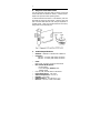
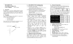
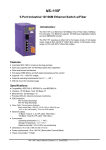
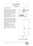
1
AFP1100 / AFP1200
Fast Ethernet 100Base-FX
User’s Manual
(9802-REV. D1)
1.
Checklist
Before you start installing the AFP1100/1200, verify that the
package contains the following items:
— AFP1100/1200 Board
— LAN Driver Diskette
— This User’s Manual
Please notify your sales representative immediately if any of
the aforementioned items is missing or damaged.
2.
Overview
AFP1100/1200 is a PCI Fast Ethernet Board that fully
complies with all IEEE 802.3u, 100Base-FX standards. Four
LED indicators (LINK, ACT, COL and FDX) on the bracket
will help to oversee the network/board link, activities,
collision and full-duplex status.
3.
AFP1100/1200 PCI Configuration
For motherboards with automatic PCI configuration:
— No specific setup is needed
— You can enter the system BIOS setup menu to
view or specify the interrupt line of the PCI slots
For Motherboards with bus master & interrupt jumpers:
—
—
Enable bus master operation in a selected PCI
slot and select an interrupt (IRQ) level using the
appropriate motherboard jumper.
Enable I/O on the AFP1100/1200 PCI slot
2
4.
PCI Bus System & Configuration
•
Ensure that the PCI machine does support master slots,
INT multiple sharing and timing compatibility. Do not
install AFP1100/1200 in PCI slave slots. Please refer to
your PCI system manual and select the appropriate
configuration settings.
When installing multiple AFP1100/1200 boards at the
server station, you should correctly configure the IRQ
settings of the PCI slot. Up to four AFP1100/1200
boards can be installed in a PCI file server running
NetWare system. The AFP1100/1200 server boards
share the same interrupt line with the driver supporting
multiple INT services at a time. Each AFP1100/1200’s
IRQ should not conflict with that of other board.
Operation in full or half-duplex (Default) mode is
configured by LAN driver options. The operating mode
should match the remote link device’s working status.
You must use EMM386 version 4.49 or higher, and
install both DOS & EMM386 that came from the same
DOS package to avoid software problems.
•
•
•
5.
Network Connection
100Base-FX/TX network allows 512-bit time delay between
any two node stations in a collision domain. The Fiber/TP
cables with devices' bit-time delay (round trip) are as below:
100Base-FX
DTE < - > DTE
Class II Hub
Fiber Cable
100Base-TX
: 100
: 92
: 1.00/m
DTE < - > DTE
Class II Hub
Cat. 5 TP Wire
DTE FX to DTE TX
100 Base-FX to 100 Base-TX Converter
: 100
: 92
: 1.12/m
: 100
: 56
The overall bit-time of Fiber/TP wires and devices must be
within 512 bit in a segment. You may use Switching Hub to
break up collision domain and extend the cabling distance.
•
Fiber Cable (multi-mode) Limitations:
Half-duplex Class II Hub
Node to Node
Node to Hub
Hub to Hub
:
:
:
205m
100m
5m
Half-duplex Switching Hub Node to Node
Node to Hub
Hub to Hub
Full-duplex Switching Hub Node to Node
Node to Hub
Hub to Hub
:
:
:
:
:
:
412m
412m
412m
2km
2km
2km
For connecting to Router, Bridge, or Switching Hub, please
refer to the device’s Technical Manual.
3
6.
Diagnostic LEDs & Boot ROM
The Link LED lights when fiber cable connection is good and
the Act LED blinks to indicate the activity. Collision and fullduplex LED report the board’s operating status.
To add the Remote Boot feature to a workstation, insert the
Boot ROM into socket as shown below. Align the notch and
pins on the Boot ROM with the notch and pin receptacles on
the ROM socket. Gently push the Boot ROM into the socket,
being careful not to bend the pins.
7.
Technical Specifications
•
•
Standard : IEEE 802.3u Fast Ethernet 100Base-FX
Connector :
— AFP1100 : SC Tx/Rx (multi-mode) connectors
— AFP1200 : ST Tx/Rx (multi-mode) connectors
•
Cable :
Fiber 50/125, 62.5/125, 100/140 µm multi-mode
Data Transfer Mode/Speed :
— PCI bus master
— Full or half-duplex (Default) mode
— 100Mbps speed
Link, ACT, COL, and FDX LEDs on the bracket
Power Requirement : 2.0A @+5V
Ambient Temperature : 0o to 50o C
Humidity : 5% to 90%
PCB Dimensions : 123 x 80 mm ( L x H )
Emission : FCC Part 15 Class A & CE Mark
•
•
•
•
•
•
•