1
GE
Measurement & Control
Validation
CTR-80
User’s Manual
M4336 Rev. D
April 2013
GE
Measurement & Control
CTR-80
Kaye Cold Temperature Reference
User’s Manual
M4336 Rev. D
April 2013
http://www.ge-mcs.com/en/validation-and-environmental-monitoring.html
©2013 General Electric Company. All rights reserved.
Technical content subject to change without notice.
Contents
Chapter 1. Before You Start
1.1 Symbols Used . . . . . . . . . . . . . . . . . . . . . . . . . . . . . . . . . . . . . . . . . . . . . . . . . . . . . . . . . . . . . . 1
1.1.1 Safety Information . . . . . . . . . . . . . . . . . . . . . . . . . . . . . . . . . . . . . . . . . . . . . . . . . . . . . 2
1.1.2 Warnings . . . . . . . . . . . . . . . . . . . . . . . . . . . . . . . . . . . . . . . . . . . . . . . . . . . . . . . . . . . . . 3
1.1.3 Cautions . . . . . . . . . . . . . . . . . . . . . . . . . . . . . . . . . . . . . . . . . . . . . . . . . . . . . . . . . . . . . 6
1.1.4 Cautions — Cold Baths . . . . . . . . . . . . . . . . . . . . . . . . . . . . . . . . . . . . . . . . . . . . . . . . . 9
1.1.5 Customer Service Information . . . . . . . . . . . . . . . . . . . . . . . . . . . . . . . . . . . . . . . . . . . 10
Chapter 2. Specifications and Environmental Conditions
2.1 Introduction . . . . . . . . . . . . . . . . . . . . . . . . . . . . . . . . . . . . . . . . . . . . . . . . . . . . . . . . . . . . . . . 11
2.2 Specifications . . . . . . . . . . . . . . . . . . . . . . . . . . . . . . . . . . . . . . . . . . . . . . . . . . . . . . . . . . . . . . 12
2.2.1 Range . . . . . . . . . . . . . . . . . . . . . . . . . . . . . . . . . . . . . . . . . . . . . . . . . . . . . . . . . . . . . . 12
2.2.2 Ambient Operating Range . . . . . . . . . . . . . . . . . . . . . . . . . . . . . . . . . . . . . . . . . . . . . . 12
2.2.3 Stability. . . . . . . . . . . . . . . . . . . . . . . . . . . . . . . . . . . . . . . . . . . . . . . . . . . . . . . . . . . . . 12
2.2.4 Uniformity . . . . . . . . . . . . . . . . . . . . . . . . . . . . . . . . . . . . . . . . . . . . . . . . . . . . . . . . . . 12
2.2.5 Set-Point Accuracy . . . . . . . . . . . . . . . . . . . . . . . . . . . . . . . . . . . . . . . . . . . . . . . . . . . . 12
2.2.6 Set-Point Repeatability . . . . . . . . . . . . . . . . . . . . . . . . . . . . . . . . . . . . . . . . . . . . . . . . . 12
2.2.7 Resolution. . . . . . . . . . . . . . . . . . . . . . . . . . . . . . . . . . . . . . . . . . . . . . . . . . . . . . . . . . . 12
2.2.8 Access Opening . . . . . . . . . . . . . . . . . . . . . . . . . . . . . . . . . . . . . . . . . . . . . . . . . . . . . . 12
2.2.9 Immersion Depth . . . . . . . . . . . . . . . . . . . . . . . . . . . . . . . . . . . . . . . . . . . . . . . . . . . . . 12
2.2.10 Tank Capacity . . . . . . . . . . . . . . . . . . . . . . . . . . . . . . . . . . . . . . . . . . . . . . . . . . . . . . . . 13
2.2.11 Cooling Time . . . . . . . . . . . . . . . . . . . . . . . . . . . . . . . . . . . . . . . . . . . . . . . . . . . . . . . . 13
2.2.1 Heater Power . . . . . . . . . . . . . . . . . . . . . . . . . . . . . . . . . . . . . . . . . . . . . . . . . . . . . . . . 13
2.2.2 Automation Package . . . . . . . . . . . . . . . . . . . . . . . . . . . . . . . . . . . . . . . . . . . . . . . . . . . 13
2.2.3 Power . . . . . . . . . . . . . . . . . . . . . . . . . . . . . . . . . . . . . . . . . . . . . . . . . . . . . . . . . . . . . . 13
2.2.4 Size . . . . . . . . . . . . . . . . . . . . . . . . . . . . . . . . . . . . . . . . . . . . . . . . . . . . . . . . . . . . . . . . 13
2.2.5 Weight. . . . . . . . . . . . . . . . . . . . . . . . . . . . . . . . . . . . . . . . . . . . . . . . . . . . . . . . . . . . . . 13
2.3 Environmental Conditions . . . . . . . . . . . . . . . . . . . . . . . . . . . . . . . . . . . . . . . . . . . . . . . . . . . . 14
2.4 Customer Site Assistance . . . . . . . . . . . . . . . . . . . . . . . . . . . . . . . . . . . . . . . . . . . . . . . . . . . . . 14
CTR-80 User’s Manual
iii
Contents
Chapter 3. Quick Start
3.1
3.2
3.3
3.4
3.5
Introduction . . . . . . . . . . . . . . . . . . . . . . . . . . . . . . . . . . . . . . . . . . . . . . . . . . . . . . . . . . . . . . . 15
Unpacking . . . . . . . . . . . . . . . . . . . . . . . . . . . . . . . . . . . . . . . . . . . . . . . . . . . . . . . . . . . . . . . . 15
Setup. . . . . . . . . . . . . . . . . . . . . . . . . . . . . . . . . . . . . . . . . . . . . . . . . . . . . . . . . . . . . . . . . . . . . 16
Power . . . . . . . . . . . . . . . . . . . . . . . . . . . . . . . . . . . . . . . . . . . . . . . . . . . . . . . . . . . . . . . . . . . . 17
Setting the Temperature . . . . . . . . . . . . . . . . . . . . . . . . . . . . . . . . . . . . . . . . . . . . . . . . . . . . . . 18
Chapter 4. Installation
4.1 Bath Environment . . . . . . . . . . . . . . . . . . . . . . . . . . . . . . . . . . . . . . . . . . . . . . . . . . . . . . . . . . 21
4.2 “Dry-out” Period . . . . . . . . . . . . . . . . . . . . . . . . . . . . . . . . . . . . . . . . . . . . . . . . . . . . . . . . . . . 21
4.3 Bath Preparation and Filling . . . . . . . . . . . . . . . . . . . . . . . . . . . . . . . . . . . . . . . . . . . . . . . . . . 22
4.3.1 Filling with Fluid . . . . . . . . . . . . . . . . . . . . . . . . . . . . . . . . . . . . . . . . . . . . . . . . . . . . . 22
4.4 Power . . . . . . . . . . . . . . . . . . . . . . . . . . . . . . . . . . . . . . . . . . . . . . . . . . . . . . . . . . . . . . . . . . . . 22
Chapter 5. Bath Use
5.1 Introduction . . . . . . . . . . . . . . . . . . . . . . . . . . . . . . . . . . . . . . . . . . . . . . . . . . . . . . . . . . . . . . . 23
5.2 General Information . . . . . . . . . . . . . . . . . . . . . . . . . . . . . . . . . . . . . . . . . . . . . . . . . . . . . . . . . 23
5.3 Comparison Calibration . . . . . . . . . . . . . . . . . . . . . . . . . . . . . . . . . . . . . . . . . . . . . . . . . . . . . . 24
5.3.1 Calibration of Multiple Probes . . . . . . . . . . . . . . . . . . . . . . . . . . . . . . . . . . . . . . . . . . . 25
Chapter 6. Parts and Controls
6.1 Control Panel . . . . . . . . . . . . . . . . . . . . . . . . . . . . . . . . . . . . . . . . . . . . . . . . . . . . . . . . . . . . . . 27
6.2 Bath Tank and Lid . . . . . . . . . . . . . . . . . . . . . . . . . . . . . . . . . . . . . . . . . . . . . . . . . . . . . . . . . . 28
6.3 Back Panel . . . . . . . . . . . . . . . . . . . . . . . . . . . . . . . . . . . . . . . . . . . . . . . . . . . . . . . . . . . . . . . . 30
Chapter 7. General Operation
7.1 Bath Fluid. . . . . . . . . . . . . . . . . . . . . . . . . . . . . . . . . . . . . . . . . . . . . . . . . . . . . . . . . . . . . . . . . 31
7.1.1 Temperature Range. . . . . . . . . . . . . . . . . . . . . . . . . . . . . . . . . . . . . . . . . . . . . . . . . . . . 31
7.1.2 Viscosity . . . . . . . . . . . . . . . . . . . . . . . . . . . . . . . . . . . . . . . . . . . . . . . . . . . . . . . . . . . . 31
7.1.3 Specific Heat. . . . . . . . . . . . . . . . . . . . . . . . . . . . . . . . . . . . . . . . . . . . . . . . . . . . . . . . . 32
7.1.4 Thermal Conductivity. . . . . . . . . . . . . . . . . . . . . . . . . . . . . . . . . . . . . . . . . . . . . . . . . . 32
7.1.5 Thermal Expansion. . . . . . . . . . . . . . . . . . . . . . . . . . . . . . . . . . . . . . . . . . . . . . . . . . . . 32
7.1.6 Electrical Resistivity. . . . . . . . . . . . . . . . . . . . . . . . . . . . . . . . . . . . . . . . . . . . . . . . . . . 32
7.1.7 Fluid Lifetime . . . . . . . . . . . . . . . . . . . . . . . . . . . . . . . . . . . . . . . . . . . . . . . . . . . . . . . . 32
iv
CTR-80 User’s Manual
Contents
7.2
7.3
7.4
7.5
7.6
7.1.7aSafety. . . . . . . . . . . . . . . . . . . . . . . . . . . . . . . . . . . . . . . . . . . . . . . . . . . . . . . . . . . . 33
7.1.8 Cost. . . . . . . . . . . . . . . . . . . . . . . . . . . . . . . . . . . . . . . . . . . . . . . . . . . . . . . . . . . . . . . . 33
7.1.9 Commonly Used Fluids . . . . . . . . . . . . . . . . . . . . . . . . . . . . . . . . . . . . . . . . . . . . . . . . 34
7.1.9aWater (Distilled) . . . . . . . . . . . . . . . . . . . . . . . . . . . . . . . . . . . . . . . . . . . . . . . . . . . 34
7.1.9bEthanol . . . . . . . . . . . . . . . . . . . . . . . . . . . . . . . . . . . . . . . . . . . . . . . . . . . . . . . . . . 34
7.1.9cMineral Oil . . . . . . . . . . . . . . . . . . . . . . . . . . . . . . . . . . . . . . . . . . . . . . . . . . . . . . . 34
7.1.9dSilicone Oil (Dow Corning 200.05, 200.10, 200.20) . . . . . . . . . . . . . . . . . . . . . . . 35
7.1.10 Fluid Characteristics Table . . . . . . . . . . . . . . . . . . . . . . . . . . . . . . . . . . . . . . . . . . . . . . 35
7.1.11 Limitations and Disclaimer . . . . . . . . . . . . . . . . . . . . . . . . . . . . . . . . . . . . . . . . . . . . . 37
Stirring . . . . . . . . . . . . . . . . . . . . . . . . . . . . . . . . . . . . . . . . . . . . . . . . . . . . . . . . . . . . . . . . . . . 37
Power . . . . . . . . . . . . . . . . . . . . . . . . . . . . . . . . . . . . . . . . . . . . . . . . . . . . . . . . . . . . . . . . . . . . 38
Heater . . . . . . . . . . . . . . . . . . . . . . . . . . . . . . . . . . . . . . . . . . . . . . . . . . . . . . . . . . . . . . . . . . . . 38
Refrigeration . . . . . . . . . . . . . . . . . . . . . . . . . . . . . . . . . . . . . . . . . . . . . . . . . . . . . . . . . . . . . . 39
7.5.1 Operation . . . . . . . . . . . . . . . . . . . . . . . . . . . . . . . . . . . . . . . . . . . . . . . . . . . . . . . . . . . 39
7.5.2 Important Refrigerant Information . . . . . . . . . . . . . . . . . . . . . . . . . . . . . . . . . . . . . . . . 39
Temperature Controller . . . . . . . . . . . . . . . . . . . . . . . . . . . . . . . . . . . . . . . . . . . . . . . . . . . . . . 40
CTR-80 User’s Manual
v
Contents
Chapter 8. Controller Operation
8.1 Introduction . . . . . . . . . . . . . . . . . . . . . . . . . . . . . . . . . . . . . . . . . . . . . . . . . . . . . . . . . . . . . . . 41
8.2 Bath Temperature . . . . . . . . . . . . . . . . . . . . . . . . . . . . . . . . . . . . . . . . . . . . . . . . . . . . . . . . . . . 41
8.3 Temperature Set-point . . . . . . . . . . . . . . . . . . . . . . . . . . . . . . . . . . . . . . . . . . . . . . . . . . . . . . . 43
8.3.1 Programmable Set-points . . . . . . . . . . . . . . . . . . . . . . . . . . . . . . . . . . . . . . . . . . . . . . . 43
8.3.2 Set-point Value . . . . . . . . . . . . . . . . . . . . . . . . . . . . . . . . . . . . . . . . . . . . . . . . . . . . . . . 44
8.3.3 Temperature Scale Units. . . . . . . . . . . . . . . . . . . . . . . . . . . . . . . . . . . . . . . . . . . . . . . . 45
8.4 Scan . . . . . . . . . . . . . . . . . . . . . . . . . . . . . . . . . . . . . . . . . . . . . . . . . . . . . . . . . . . . . . . . . . . . . 45
8.4.1 Scan Control . . . . . . . . . . . . . . . . . . . . . . . . . . . . . . . . . . . . . . . . . . . . . . . . . . . . . . . . . 45
8.4.2 Scan Rate . . . . . . . . . . . . . . . . . . . . . . . . . . . . . . . . . . . . . . . . . . . . . . . . . . . . . . . . . . . 46
8.5 Secondary Menu . . . . . . . . . . . . . . . . . . . . . . . . . . . . . . . . . . . . . . . . . . . . . . . . . . . . . . . . . . . 46
8.6 Heater Power . . . . . . . . . . . . . . . . . . . . . . . . . . . . . . . . . . . . . . . . . . . . . . . . . . . . . . . . . . . . . . 47
8.7 Proportional Band . . . . . . . . . . . . . . . . . . . . . . . . . . . . . . . . . . . . . . . . . . . . . . . . . . . . . . . . . . 48
8.8 Cutout. . . . . . . . . . . . . . . . . . . . . . . . . . . . . . . . . . . . . . . . . . . . . . . . . . . . . . . . . . . . . . . . . . . . 50
8.9 Controller Configuration . . . . . . . . . . . . . . . . . . . . . . . . . . . . . . . . . . . . . . . . . . . . . . . . . . . . . 51
8.10 Operating Parameters . . . . . . . . . . . . . . . . . . . . . . . . . . . . . . . . . . . . . . . . . . . . . . . . . . . . . . 52
8.10.1 High Limit . . . . . . . . . . . . . . . . . . . . . . . . . . . . . . . . . . . . . . . . . . . . . . . . . . . . . . . . . . 52
8.10.2 Low Limit . . . . . . . . . . . . . . . . . . . . . . . . . . . . . . . . . . . . . . . . . . . . . . . . . . . . . . . . . . . 53
8.11 Cooling . . . . . . . . . . . . . . . . . . . . . . . . . . . . . . . . . . . . . . . . . . . . . . . . . . . . . . . . . . . . . . . . . . 54
8.12Serial Interface Parameters . . . . . . . . . . . . . . . . . . . . . . . . . . . . . . . . . . . . . . . . . . . . . . . . . . . 55
8.12.1 Baud Rate . . . . . . . . . . . . . . . . . . . . . . . . . . . . . . . . . . . . . . . . . . . . . . . . . . . . . . . . . . . 55
8.12.2 Sample Period. . . . . . . . . . . . . . . . . . . . . . . . . . . . . . . . . . . . . . . . . . . . . . . . . . . . . . . . 56
8.12.3 Duplex Mode . . . . . . . . . . . . . . . . . . . . . . . . . . . . . . . . . . . . . . . . . . . . . . . . . . . . . . . . 57
8.12.3aLinefeed. . . . . . . . . . . . . . . . . . . . . . . . . . . . . . . . . . . . . . . . . . . . . . . . . . . . . . . . . 57
8.13Calibration Parameters . . . . . . . . . . . . . . . . . . . . . . . . . . . . . . . . . . . . . . . . . . . . . . . . . . . . . . . 58
8.13.1 Hard Cutout . . . . . . . . . . . . . . . . . . . . . . . . . . . . . . . . . . . . . . . . . . . . . . . . . . . . . . . . . 59
8.13.2 R0 . . . . . . . . . . . . . . . . . . . . . . . . . . . . . . . . . . . . . . . . . . . . . . . . . . . . . . . . . . . . . . . . . 59
8.13.3 ALPHA . . . . . . . . . . . . . . . . . . . . . . . . . . . . . . . . . . . . . . . . . . . . . . . . . . . . . . . . . . . . . 59
8.13.4 DELTA . . . . . . . . . . . . . . . . . . . . . . . . . . . . . . . . . . . . . . . . . . . . . . . . . . . . . . . . . . . . . 59
8.13.5 BETA . . . . . . . . . . . . . . . . . . . . . . . . . . . . . . . . . . . . . . . . . . . . . . . . . . . . . . . . . . . . . . 59
vi
CTR-80 User’s Manual
Contents
Chapter 9. Digital Communications Interface
9.1 Introduction . . . . . . . . . . . . . . . . . . . . . . . . . . . . . . . . . . . . . . . . . . . . . . . . . . . . . . . . . . . . . . . 61
9.2 Serial Communications . . . . . . . . . . . . . . . . . . . . . . . . . . . . . . . . . . . . . . . . . . . . . . . . . . . . . . 61
9.3 Wiring. . . . . . . . . . . . . . . . . . . . . . . . . . . . . . . . . . . . . . . . . . . . . . . . . . . . . . . . . . . . . . . . . . . . 62
9.3.1 Setup . . . . . . . . . . . . . . . . . . . . . . . . . . . . . . . . . . . . . . . . . . . . . . . . . . . . . . . . . . . . . . . 63
9.3.1aBaud Rate . . . . . . . . . . . . . . . . . . . . . . . . . . . . . . . . . . . . . . . . . . . . . . . . . . . . . . . . 63
9.3.1bSample Period . . . . . . . . . . . . . . . . . . . . . . . . . . . . . . . . . . . . . . . . . . . . . . . . . . . . . 63
9.3.1cDuplex Mode. . . . . . . . . . . . . . . . . . . . . . . . . . . . . . . . . . . . . . . . . . . . . . . . . . . . . . 63
9.3.1dLinefeed . . . . . . . . . . . . . . . . . . . . . . . . . . . . . . . . . . . . . . . . . . . . . . . . . . . . . . . . . 64
9.3.2 Serial Operation . . . . . . . . . . . . . . . . . . . . . . . . . . . . . . . . . . . . . . . . . . . . . . . . . . . . . . 64
9.4 Interface Commands . . . . . . . . . . . . . . . . . . . . . . . . . . . . . . . . . . . . . . . . . . . . . . . . . . . . . . . . 64
Chapter 10. Calibration Procedure
10.1Introduction . . . . . . . . . . . . . . . . . . . . . . . . . . . . . . . . . . . . . . . . . . . . . . . . . . . . . . . . . . . . . . . 69
10.2Calibration Equipment . . . . . . . . . . . . . . . . . . . . . . . . . . . . . . . . . . . . . . . . . . . . . . . . . . . . . . . 69
10.3Calibration . . . . . . . . . . . . . . . . . . . . . . . . . . . . . . . . . . . . . . . . . . . . . . . . . . . . . . . . . . . . . . . . 69
Chapter 11. Maintenance
11.1Bath Maintenance . . . . . . . . . . . . . . . . . . . . . . . . . . . . . . . . . . . . . . . . . . . . . . . . . . . . . . . . . . 71
Chapter 12. Troubleshooting
12.1Introduction . . . . . . . . . . . . . . . . . . . . . . . . . . . . . . . . . . . . . . . . . . . . . . . . . . . . . . . . . . . . . . . 73
12.2Troubleshooting . . . . . . . . . . . . . . . . . . . . . . . . . . . . . . . . . . . . . . . . . . . . . . . . . . . . . . . . . . . . 73
12.3CE Comments . . . . . . . . . . . . . . . . . . . . . . . . . . . . . . . . . . . . . . . . . . . . . . . . . . . . . . . . . . . . . 75
12.3.1 EMC Directive . . . . . . . . . . . . . . . . . . . . . . . . . . . . . . . . . . . . . . . . . . . . . . . . . . . . . . . 75
12.3.2 Low Voltage Directive (Safety) . . . . . . . . . . . . . . . . . . . . . . . . . . . . . . . . . . . . . . . . . . 75
CTR-80 User’s Manual
vii
Contents
viii
CTR-80 User’s Manual
Chapter 1. Before You Start
Chapter 1.
Before You Start
1.1 Symbols Used
Table 1 below lists the International Electrical Symbols. Some or all of these symbols may
be used on the CTR-80 or in this manual.
Table 1: International Electrical Symbols
Symbol
Description
AC (Alternating Current)
AC-DC
Battery
Complies with European Union directives
DC
Double Insulated
Electric Shock
Fuse
PE Ground
Hot Surface (Burn Hazard)
CTR-80 User’s Manual
1
Chapter 1. Before You Start
Table 1: International Electrical Symbols (Continued)
Symbol
Description
Read the User’s Manual -- Important
Information
Off
On
Canadian Standards Association
OVERVOLTAGE (Installation) CATEGORY II, Pollution Degree 2
per IEC1010-1 refers to the level of Impulse Withstand Voltage
protection provided. Equipment of OVERVOLTAGE CATEGORY II
is energy-consuming equipment to be supplied from the fixed
installation. Examples include household, office, and laboratory
appliances.
C-TIC Australian EMC mark
1.1.1 Safety Information
Use this instrument only as specified in this manual. Otherwise, the protection provided by
the instrument may be impaired. Refer to the safety information below.
The following definitions apply to the terms “Warning” and “Caution”.
“Warning” identifies conditions and actions that may pose hazards to the user.
“Caution” identifies conditions and actions that may damage the instrument being used.
2
CTR-80 User’s Manual
Chapter 1. Before You Start
1.1.2 Warnings
To avoid personal injury, follow these guidelines:
WARNING! DO NOT use the instrument for any application other than calibration
work. The instrument was designed for temperature calibration. Any
other use of the unit may cause unknown hazards to the user.
DO NOT use the unit in environments other than those listed in the
user’s guide.
DO NOT overfill the bath. Overflowing extremely cold or hot fluid may
be harmful to the operator. See the section Bath Preparation and
Filling (page 22) for specific instructions.
Follow all safety guidelines listed in the user’s manual.
Calibration Equipment should only be used by Trained Personnel.
CTR-80 User’s Manual
3
Chapter 1. Before You Start
Warnings (cont.)
WARNING! If this equipment is used in a manner not specified by the
manufacturer, the protection provided by the equipment may be
impaired.
Before initial use, or after transport, or after storage in humid or
semi-humid environments, or anytime the instrument has not been
energized for more than 10 days, the instrument needs to be
energized for a “dry-out” period of 2 hours before it can be assumed
to meet all of the safety requirements of the IEC 1010-1. If the product
is wet or has been in a wet environment, take necessary measures to
remove moisture prior to applying power such as storage in a low
humidity temperature chamber operating at 50°C for 4 hours or
more.
DO NOT operate high temperature baths (500°C) near flammable
materials. Extreme temperatures could ignite the flammable
material.
Overhead clearance is required. Do not place the instrument under a
cabinet or other structure. Always leave enough clearance to allow
for safe and easy insertion and removal of probes.
The instrument is intended for indoor use only.
!BURN HAZARD!
Extremely cold temperatures may be present in this equipment.
Freezer burns and frostbite may result if personnel fail to observe
safety precautions.
High temperatures may be present in this equipment. Fires and
severe burns may result if personnel fail to observe safety
precautions.
4
CTR-80 User’s Manual
Chapter 1. Before You Start
Warnings (cont.)
!ELECTRICAL HAZARD!
These guidelines must be followed to ensure that the safety
mechanisms in this instrument will operate properly. This instrument
must be plugged into a 115 VAC, 60 Hz (230 VAC, 50 Hz optional), AC
only electric outlet. The power cord of the instrument is equipped
with a three-pronged grounding plug for your protection against
electrical shock hazards. It must be plugged directly into a properly
grounded three-prong receptacle. The receptacle must be installed in
accordance with local codes and ordinances. Consult a qualified
electrician. DO NOT use an extension cord or adapter plug.
DO use a ground fault interrupt device. This unit contains a liquid. A
ground fault device is advised in case liquid is present in the electrical
system and could cause an electrical shock.
Always replace the power cord with an approved cord of the correct
rating and type. If you have questions, contact GE Sensing Customer
Service.
High voltage is used in the operation of this equipment. Severe injury
or death may result if personnel fail to observe the safety
precautions. Before working inside the equipment, turn off the power
and disconnect the power cord.
CTR-80 User’s Manual
5
Chapter 1. Before You Start
Warnings (cont.)
!BATH FLUIDS!
Fluids used in this unit may produce noxious or toxic fumes under
certain circumstances. Consult the fluid manufacturer’s MSDS
(Material Safety Data Sheet). Proper ventilation and safety
precautions must be observed.
The instrument is equipped with a soft cutout (user settable firmware)
and a hard cutout (set at the factory). Check the flash point, boiling
point, or other fluid characteristic applicable to the circumstances of
the unit operation.
Ensure that the soft cutout is adjusted to the fluid characteristics of
the application. As a guideline, the soft cutout should be set 10°C to
15°C below the flash point of the bath fluid. See Table 2 on page 36 for
specific information on bath fluids and the section Cutout
(page 8-10).
1.1.3 Cautions
CAUTION!
The drain valve comes installed with the bath. Ensure that the drain valve is
closed prior to filling the bath with fluid.
Always operate this instrument at room temperature between 41°F and
122°F (5°C to 50°C). Allow sufficient air circulation by leaving at least 6 inches
(15 cm) of clearance around the instrument.
6
CTR-80 User’s Manual
Chapter 1. Before You Start
Cautions (cont.)
CAUTION!
DO NOT overfill the bath. Overflowing liquid may damage the
electrical system. Be sure to allow for thermal expansion of the fluid
as the bath temperature increases. See the section Bath Preparation
and Filling (page 22) for specific instructions.
DO NOT change the values of the bath calibration constants from the
factory set values. The correct setting of these parameters is
important to the safety and proper operation of the unit.
The refrigeration may be damaged or the lifetime shortened if the
set-point temperature is set above 60°C for more than one hour with
the refrigeration manually on. Ensure that the refrigeration is off
when the unit is
used above 60°C.
The Factory Reset Sequence should be performed only by authorized
personnel if no other action is successful in correcting a malfunction.
You must have a copy of the most recent Report of Test to restore the
test parameters.
DO NOT operate this instrument in an excessively wet, oily, dusty, or
dirty environment.
CTR-80 User’s Manual
7
Chapter 1. Before You Start
Cautions (cont.)
CAUTION!
The unit is a precision instrument. Although it has been designed for
optimum durability and trouble free operation, it must be handled
with care. Position the unit before the tank is filled with fluid. Use the
handles provided to move the unit. Due to the weight of the
compressor, it may require two people to safely move the bath. If two
people are used, place one person in the front and one person in the
back of the unit, carefully slide hands under the unit, and lift in
unison. The area containing the compressor will be heavier than the
rest of the unit. Do not move a unit filled with fluid.
Most probes have handle temperature limits. Be sure that the probe
handle temperature limit is not exceeded in the air above the
instrument.
The instrument and any thermometer probes used with it are
sensitive instruments that can be easily damaged. Always handle
these devices with care. Do not allow them to be dropped, struck,
stressed, or overheated.
8
CTR-80 User’s Manual
Chapter 1. Before You Start
1.1.4 Cautions ― Cold Baths
CAUTION!
Refrigerated baths require that the condensing coil be cleaned
periodically. Accumulation of dust and dirt on the condenser will
result in premature failure of the compressor.
This bath has been equipped with a brownout and over voltage
protection device as a safety feature to protect the system
components.
Mode of Operation: This bath needs to be plugged into the line voltage
for at least 2 minutes before operation. This is only necessary for the
first time that the bath is energized or when it is moved from one
location to another. Turning the bath ON or OFF does not trigger the
delay.
If a High/Low voltage condition exists for longer than 5 seconds, the
bath de-energizes. An amber indicator on the back panel lights when
this condition exists.
Re-energization is automatic upon correction of the fault condition
and after a delay cycle of about 2 minutes. If a fault condition exists
upon application of power, the bath will not energize.
Under and Over Voltage Protection at 115 VAC
Voltage Cutout: ±12.5% (101 - 129 VAC)
Voltage Cut In: ±7.5% (106 - 124 VAC)
Under and Over Voltage Protection at 230 VAC
Voltage Cutout: ±12.5% (203 - 257 VAC)
Voltage Cut In: ±7.5% (213 - 247 VAC)
CTR-80 User’s Manual
9
Chapter 1. Before You Start
1.1.5 Customer Service Information
When contacting GE Customer Service, please have the following information available:
•
Model Number
•
Serial Number
•
Voltage
•
Complete description of the problem.
10
CTR-80 User’s Manual
Chapter 2. Specifications and Environmental Conditions
Chapter 2.
Specifications and Environmental
Conditions
2.1 Introduction
The Kaye CTR –80 is an ultra low temp bath useful in temperature calibration and other
applications requiring stable temperatures. An innovative state of the art solid-state
temperature controller has been incorporated which maintains the bath temperature with
extreme stability. The temperature controller uses a micro-controller to execute the many
operating functions.
The user interface is provided by the 8-digit LED display and four key-switches. Digital
remote communications is available with an RS-232 interface.
The CTR –80 was designed to be compact and low cost without compromising
performance. The CTR –80 operates over a wide temperature range from –80°C to 30°C
and from 50°C to 100°C.
CTR-80 User’s Manual
11
Chapter 2. Specifications and Environmental Conditions
2.2 Specifications
2.2.1 Range
–80°C to 100°C (–112°F to 212°F)
2.2.2 Ambient Operating Range
15°C to 25°C (59°F to 77°F)
2.2.3 Stability
±0.006°C at –80°C (ethanol)
±0.010°C at 0°C (ethanol)
±0.010°C at 100°C (oil)
2.2.4 Uniformity
±0.008°C at –80°C (ethanol)
±0.012°C at 0°C (ethanol)
±0.012°C at 100°C (oil)
2.2.5 Set-Point Accuracy
±0.5°C
2.2.6 Set-Point Repeatability
±0.01°C
2.2.7 Resolution
0.01°
2.2.8 Access Opening
3.25" x 4.5" (86 x 114 mm)
2.2.9 Immersion Depth
7" (180 mm) max
12
CTR-80 User’s Manual
Chapter 2. Specifications and Environmental Conditions
2.2.10 Tank Capacity
1 gallon (4 liters)
2.2.11 Cooling Time
From 25°C to –80°C, 130 minutes
2.2 Refrigeration Cascade
Two ¼ HP compressors
2.2.1 Heater Power
500 W
2.2.2 Automation Package
Interface-it software and RS-232 included
2.2.3 Power
115 VAC (±10%), 60 Hz, 15 A or 230 VAC (±10%), 50 Hz, 8 A, 1700 VA
2.2.4 Size
12" W x 30" H x 24" D (305 x 762 x 610 mm)
2.2.5 Weight
115 lb. (52 kg)
CTR-80 User’s Manual
13
Chapter 2. Specifications and Environmental Conditions
2.3 Environmental Conditions
Although the instrument has been designed for optimum durability and trouble-free
operation, it must be handled with care. The instrument should not be operated in an
excessively dusty or dirty environment. Maintenance and cleaning recommendations can
be found in Chapter 11, Maintenance.
The instrument operates safely under the following conditions:
•
temperature range: 15–30°C (59–86°F)
•
ambient relative humidity: 15–50%
•
pressure: 75 kPa–106 kPa
•
mains voltage within ±10% of nominal
•
vibrations in the calibration environment should be minimized
•
altitude less than 2,000 meters
2.4 Customer Site Assistance
GE can provide optional onsite assistance with installation, initial operation, and training
of plant personnel. Contact Customer Service for details.
14
CTR-80 User’s Manual
Chapter 3. Quick Start
Chapter 3.
Quick Start
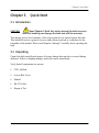
3.1 Introduction
CAUTION!
Read Chapter 5, Bath Use, before placing the bath in service.
Incorrect handling can damage the bath and void the warranty.
This chapter gives a brief summary of the steps required to set up and operate the bath.
This should be used as a general overview and reference and not as a substitute for the
remainder of the manual. Please read Chapters 4 through 7 carefully before operating the
bath.
3.2 Unpacking
Unpack the bath carefully and inspect it for any damage that may have occurred during
shipment. If there is shipping damage, notify the carrier immediately.
Verify that all components are present:
•
CTR –80 Bath
•
Access Hole Cover
•
Manual
•
RS-232 Cable
•
Report of Test
CTR-80 User’s Manual
15
Chapter 3. Quick Start
3.3 Setup
CAUTION!
The drain valve must be closed on the back of the bath before
attempting to fill the tank with fluid.
WARNING!
The instrument is equipped with a soft cutout (user settable
firmware) and a hard cutout (set at the factory). Check the flash point,
boiling point, or other fluid characteristic applicable to the
circumstances of the unit operation. Ensure that the soft cutout is
adjusted to the fluid characteristics of the application. As a guideline,
the soft cutout should be set 10°C to 15°C below the flash point of the
bath fluid. See Table 2 on page 36 for specific information on bath
fluids and the section Cutout (page 50).
Setup of the bath requires careful unpacking and placement of the bath, filling the bath
with fluid, and connecting power. Consult Chapter 4 for detailed instructions for proper
installation of the bath. Be sure to place the bath in a safe, clean and level location.
Fill the bath tank with an appropriate liquid. For operation at moderate bath temperatures,
clean distilled water works well. For lower temperatures, ethanol (denatured) works well
but is NOT USABLE AT HIGHER TEMPERATURES due to flammability.
Carefully pour the fluid into the bath tank through the large rectangular access hole above
the tank avoiding spilling any fluid. The fluid must not exceed a height of 1/2 inch below
the top of the tank or be less than 2 inches below the top.
16
CTR-80 User’s Manual
Chapter 3. Quick Start
3.4 Power
Plug the bath power cord into a mains outlet of the proper voltage, frequency, and current
capability. See Chapter 2, Specifications and Environmental Conditions, for power details.
Refer to and read the CAUTION at the front of this manual concerning brownout and over
voltage protection.
Turn the bath on using the front panel “POWER” switch. The bath will turn on and begin
to heat or cool to reach the previously programmed temperature set-point. The front panel
LED display will indicate the actual bath temperature. Set the cooling switch to “OFF” for
temperatures above approximately 50°C. Set the switch to “ON” for lower temperatures.
When the cooling switch has been turned on, the first stage compressor will power up. The
second stage will come on automatically when proper conditions are met. This will take 2
to 4 minutes. Cooling in the bath will not begin until the second stage starts.
CTR-80 User’s Manual
17
Chapter 3. Quick Start
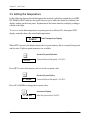
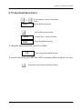
3.5 Setting the Temperature
In the following discussion and throughout this manual a solid box around the word SET,
UP, DOWN or EXIT indicates the panel button to press while the dotted box indicates the
display reading on the front panel. Explanation of the button function or display reading is
written at the right.
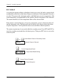
To view or set the bath temperature set-point proceed as follows.The front panel LED
display normally shows the actual bath temperature.
24.68 C
Bath Temperature Display
When SET is pressed, the display shows the set-point memory that is currently being used
and its value. Eight set-point memories are available.
Access Set-point Selection
1.25.0
Current Value of Set-point 1, 25.00°C
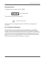
Press SET to select this memory and access the set-point value.
Access Set-point Value
C 25.00
Current Value of Set-point 1, 25.00°C
Press UP or DOWN to change the set-point value.
Increment Display
C 30.00
18
New Set-point Value, 30.00°C
CTR-80 User’s Manual
Chapter 3. Quick Start
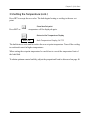
3.5 Setting the Temperature (cont.)
Press SET to accept the new value. The bath begins heating or cooling to the new setpoint.
Store New Set-point
Press EXIT and the bath temperature will be displayed again.
Return to the Temperature Display
24.73 C
Bath Temperature Display, 24.73°C
The bath heats or cools until it reaches the new set-point temperature. Turn off the cooling
to reach and control at higher temperatures.
When setting the set-point temperature be careful not to exceed the temperature limit of
the bath fluid.
To obtain optimum control stability, adjust the proportional band as discussed on page 48.
CTR-80 User’s Manual
19
Chapter 3. Quick Start
[no content intended for this page - proceed to next page]
20
CTR-80 User’s Manual
Chapter 4. Installation
Chapter 4.
Installation
4.1 Bath Environment
CAUTION!
Read Chapter 5, Bath Use, before placing the bath in service.
Incorrect handling can damage the bath and void the warranty.
The CTR –80 Bath is a precision instrument which should be located in an appropriate
environment. The location should be free of drafts, extreme temperatures and temperature
changes, dirt, etc. The surface where the bath is placed must be level. Allow at least six
inches around the bath for air circulation. The top surface of the bath may become hot at
high temperatures. Beware of the danger of accidental fluid spills.
A fume hood should be used to remove any vapors given off by hot bath fluid.
4.2 “Dry-out” Period
Before initial use, after transport, and any time the instrument has not been energized for
more than 10 days, the bath will need to be energized for a “dry-out” period of 1-2 hours
before it can be assumed to meet all of the safety requirements of the IEC 1010-1.
CTR-80 User’s Manual
21
Chapter 4. Installation
4.3 Bath Preparation and Filling
CAUTION!
The drain valve comes installed with the bath. Ensure that the
drain valve is closed prior to filling the bath with fluid.
4.3.1 Filling with Fluid
The CTR –80 Bath is not provided with a fluid. Depending on the desired temperature
range, any of the following fluids, as well as others, may be used in the bath:
•
•
•
•
•
•
Water
Ethanol (Ethyl Alcohol)
Ethylene glycol/water
Mineral oil
Silicone oil
Halocarbon 0.8
Fluids are discussed in detail in Chapter 7. Remove any access hole cover from the bath
and check the tank for foreign matter (dirt, remnant packing material, etc.). Ensure the
valve handle is in the closed position before attempting to add fluid to the tank.
Fill the bath with clean unpolluted fluid. Fill the bath carefully through the large square
access hole to a level that will allow for stirring and thermal expansion.
DO NOT turn on the bath without fluid in the tank. The fluid should never exceed a height
of 1/2” below the top of the tank or be less than 2 inches below the top. Carefully monitor
the bath fluid level as the bath temperature rises to prevent overflow or splashing.
Cautiously, remove excess hot fluid if necessary.
4.4 Power
With the bath power switch off, plug the bath into an AC mains outlet of the appropriate
voltage, frequency, and current capacity. See Chapter 2, Specifications and Environmental
Conditions, for power details. Refer to and read the CAUTION at the front of this manual
concerning brownout and over voltage protection.
22
CTR-80 User’s Manual
Chapter 5. Bath Use
Chapter 5.
Bath Use
5.1 Introduction
CAUTION!
READ THIS SECTION BEFORE PLACING THE BATH IN SERVICE.
The information in this section is for general information only. It is not designed to be the
basis for calibration laboratory procedures. Each laboratory will need to write its own
specific procedures.
5.2 General Information
Be sure to select the correct fluid for the temperature range of the calibration. Bath fluids
should be selected to operate safely with adequate thermal properties to meet the
application requirements. Also, be aware that some fluids expand and could overflow the
bath if not watched. Refer to Chapter 7, General Operation, for information specific to
fluid selection and to the MSDS sheet specific to the fluid selected. The temperature range
of any single fluid is likely less than that of the bath itself. This means that the type of bath
fluid may have to change to cover the full range of the bath (see page 31). Baths are most
often set up to operate with a single fluid only over the useful range of that fluid. Other
baths can be set up with other fluids to cover other temperature ranges required. This is
generally the most productive and efficient approach.
The bath generates extreme temperatures. Precautions must be taken to prevent personal
injury or damage to objects. Probes may be extremely hot or cold when removed from the
bath. Cautiously handle probes to prevent personal injury.
CTR-80 User’s Manual
23
Chapter 5. Bath Use
5.2 General Information (cont.)
Carefully place probes on a heat/cold resistant surface or rack until they are at room
temperature. It is advisable to wipe the probe with a clean soft cloth or paper towel before
inserting it into another bath. This prevents the mixing of fluids from one bath to another.
Always be sure that the probe is completely dry before inserting it into a hot fluid. Some
of the high temperature fluids react violently to water or other liquid mediums. Be
aware that cleaning the probe can be dangerous if the probe has not cooled to room
temperature.
For optimum accuracy and stability, allow the bath adequate stabilization time after
reaching the set-point temperature.
5.3 Comparison Calibration
Comparison calibration involves testing a probe (unit under test, UUT) against a reference
probe. After inserting the probes to be calibrated into the bath, allow sufficient time for the
probes to settle and the temperature of the bath to stabilize.
One of the significant dividends of using a bath rather than a dry-well to calibrate multiple
probes is that the probes do not need to be identical in construction. The fluid in the bath
allows different types of probes to be calibrated at the same time. However, stem effect
from different types of probes is not totally eliminated. Even though all baths have
horizontal and vertical gradients, these gradients are minimized inside the bath work area.
Nevertheless, probes should be inserted to the same depth in the bath liquid. Be sure that
all probes are inserted deep enough to prevent stem effect. We suggest a general rule-ofthumb for immersion depth to reduce the stem effect to a minimum: 20x the diameter of
the UUT + the sensor length.
Do not submerge the probe handles. If the probe handles get too warm during
calibration at high temperatures, a heat shield could be used just below the probe handle.
This heat shield could be as simple as aluminum foil slid over the probe before inserting it
in the bath or as complicated as a specially designed reflective metal apparatus.
When calibrating over a wide temperature range, better results can generally be achieved
by starting at the highest temperature and progressing down to the lowest temperature.
24
CTR-80 User’s Manual
Chapter 5. Bath Use
5.3 Comparison Calibration (cont.)
Probes can be held in place in the bath by using probe clamps or drilling holes in the
access cover. Other fixtures to hold the probes can be designed. The object is to keep the
reference probe and the probe(s) to be calibrated as closely grouped as possible in the
working area of the bath. Bath stability is maximized when the bath working area is kept
covered.
In preparing to use the bath for calibration, start by:
•
Placing the reference probe in the bath working area.
•
Placing the probe to be calibrated, the UUT, in the bath working area as close as
feasibly possible to the reference probe.
5.3.1 Calibration of Multiple Probes
Fully loading the bath with probes increases the time required for the temperature to
stabilize after inserting the probes. Using the reference probe as the guide, be sure that the
temperature has stabilized before starting the calibration.
CTR-80 User’s Manual
25
Chapter 5. Bath Use
[no content intended for this page - proceed to next page]
26
CTR-80 User’s Manual
Chapter 6. Parts and Controls
Chapter 6.
Parts and Controls
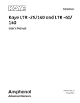
6.1 Control Panel
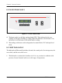
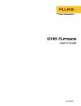
The following controls and indicators are present on the controller front panel (see Figure
6-1 on the next page): (1) the digital LED display, (2) the control buttons, (3) the on/off
power switch, (4) the heater mode light, and (5) the cooling on/off switch.
1. The digital display is an important part of the temperature controller. It displays the
set-point temperature and bath temperature as well as the various other bath functions,
settings, and constants. The display shows temperatures according to the selected
scale units °C or °F.
2. The control buttons (SET, DOWN, UP, and EXIT) are used to set the bath temperature
set-point, access and set other operating parameters, and access and set bath
calibration parameters. A brief description of the functions of the buttons follows:
•
SET - Used to display the next parameter in a menu and to set parameters to the
displayed value.
•
DOWN - Used to decrement the displayed value of parameters.
•
UP - Used to increment the displayed value.
•
EXIT - Used to exit from a menu. When EXIT is pressed, any changes made to the
displayed value will be ignored.
3. The on/off switch controls power to the entire bath including the stirring motor.
CTR-80 User’s Manual
27
Chapter 6. Parts and Controls
6.1 Control Panel (cont.)
Figure 1: CTR -80 Control Panel
4. The heater mode is a red light emitting diode (LED). This indicator lets the user
visually see the ratio of heating to cooling. When the indicator is lit the heater is on,
and when it is off the heater is off and the bath is cooling.
5. The cooling switch turns on the refrigeration for control below 50°C and rapid cool
down.
6.2 Bath Tank and Lid
The bath tank and lid assembly includes: the tank, the control probe, the stirring motor, the
access hole, and the access hole cover.
•
28
The bath tank is constructed of stainless steel. It is very resistant to oxidation in the
presence of most chemicals and over a wide range of temperatures.
CTR-80 User’s Manual
Chapter 6. Parts and Controls
6.2 Bath Tank and Use (cont.)
•
The control probe provides the temperature feedback signal to the controller allowing
the controller to maintain a constant temperature. The control probe is a precision
platinum resistance thermometer (PRT). It is delicate and must be handled carefully.
The probe is placed in the small hole in the top of the bath so that the probe tip is fully
immersed in the bath fluid. It is located underneath the motor cover.
•
The stirring motor is mounted on the bath tank lid under the motor cover. It drives the
stirring propeller to provide mixing of the bath fluid. Proper mixing of the fluid is
important for good constant temperature stability.
•
On the bath lid is a work area access hole. This is used for filling the bath with fluids
and placement of thermometers and devices into the bath. When possible, the access
hole should be covered (must be covered to reach minimum temperatures).
•
An insulated access hole cover is provided and should be used to cover the access
opening in the top of the bath. This improves bath temperature stability, prevents
excess fluid evaporation or fumes and increases safety with hot fluid. The user may
drill or cut holes in the cover to accommodate the instruments to be calibrated or
immersed in the bath. Spare covers are available from GE. An optional access cover
which provides locations for two reference thermometers and three wells for units
under test is available.
CTR-80 User’s Manual
29
Chapter 6. Parts and Controls
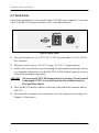
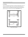
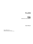
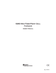
6.3 Back Panel
On the back of the bath are 1) the circuit breaker, 2) the IEC power connector, 3) the drain
valve, 4) the RS-232 interface connector, and 5) removable vent panel.
Figure 2: Back Panel
1. The circuit breakers are 15 A, 250 V for 115 VAC operation and 8 A, 250 V for 230
VAC operation.
2. The power cord is rated at 115 VAC, 15 amps. (230 VAC, 10 amps optional.)
3. A drain valve is provided for ease of removing the fluid media from the bath. Always
use a container of adequate size to hold the FULL LOAD of fluid. Some oils are more
easily drained at higher temperatures.
CAUTION!
Do not exceed a 100°C fluid temperature for draining. The valve could
be damaged if 100°C is exceeded. Insulate the container from the
floor and other objects.
4. The serial RS-232 interface attaches to the back of the bath at the connector labeled
“RS-232”.
5. The removable vent panel can be removed to access the condenser for cleaning. See
Chapter 11, Maintenance.
30
CTR-80 User’s Manual
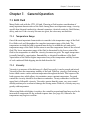
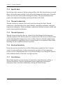
Chapter 7. General Operation
Chapter 7.
General Operation
7.1 Bath Fluid
Many fluids work with the CTR –80 bath. Choosing a fluid requires consideration of
many important characteristics of the fluid. Among these are temperature range, viscosity,
specific heat, thermal conductivity, thermal expansion, electrical resistivity, fluid lifetime,
safety, and cost. If the viscosity becomes too great, the stirrer may not function.
7.1.1 Temperature Range
One of the most important characteristics to consider is the temperature range of the fluid.
Few fluids work well throughout the complete temperature range of the bath. The
temperature at which the bath is operated must always be within the safe and useful
temperature range of the fluid. Set the cutout to meet the temperature limits of the selected
fluid. The lower temperature range of the fluid is determined by the freeze point of the
fluid or the temperature at which the viscosity becomes too great. The upper temperature
is usually limited by vaporization, flammability, or chemical breakdown of the fluid.
Vaporization of the fluid at higher temperatures may affect temperature stability because
of cool condensed fluid dripping into the bath from the lid.
7.1.2 Viscosity
Viscosity is a measure of the thickness of a fluid, how easily it can be poured and mixed.
Viscosity affects the temperature stability of the bath. With low viscosity, fluid mixing is
better which creates a more uniform temperature throughout the bath. This improves the
bath response time which allows it to maintain a more constant temperature. For good
control the viscosity should be less than ten centistokes. Twenty centistokes is about the
upper limit of allowable viscosity. Viscosities greater than this cause very poor control
stability and may also overheat or damage the stirring motor. With oils, viscosity may vary
greatly with temperature.
When using fluids with higher viscosities, the controller proportional band may need to be
increased to compensate for the reduced response time (see page 48). Otherwise the
temperature may begin to oscillate.
CTR-80 User’s Manual
31
Chapter 7. General Operation
7.1.3 Specific Heat
Specific heat is the measure of the heat storage ability of the fluid. Specific heat, to a small
degree, affects the control stability. It also affects the heating and cooling rates. Generally,
a lower specific heat means quicker heating and cooling. The proportional band may
require some adjustment depending on the specific heat of the fluid.
7.1.4 Thermal Conductivity
Thermal conductivity measures how easily heat flows through the fluid. Thermal
conductivity of the fluid affects the control stability, temperature uniformity, and probe
temperature settling time. Fluids with higher conductivity distribute heat more quickly and
evenly, improving bath performance.
7.1.5 Thermal Expansion
Thermal expansion describes how the volume of the fluid changes with temperature.
Thermal expansion of the fluid used must be considered since the increase in fluid volume
as the bath temperature changes may cause overflow. Excessive thermal expansion may
also be undesirable in applications where constant liquid level is important. Many fluids,
including oils, have significant thermal expansion.
7.1.6 Electrical Resistivity
Electrical resistivity describes how well the fluid insulates against the flow of electric
current. In some applications, such as measuring the resistance of bare temperature
sensors, it may be important that little or no electrical leakage occur through the fluid. In
such conditions choose a fluid with very high resistivity.
7.1.7 Fluid Lifetime
Many fluids degrade over time because of evaporation, water absorption, gelling, or
chemical breakdown. Often the degradation becomes significant near the upper
temperature limit of the fluid, substantially reducing the fluid’s lifetime.
32
CTR-80 User’s Manual
Chapter 7. General Operation
7.1.7a
Safety
When choosing a fluid always consider the safety issues associated. Obviously where
there are conditions of extreme hot or cold, there can be danger to people and equipment.
Fluids may also be hazardous for other reasons. Some fluids may be considered toxic.
Contact with eyes, skin, or inhalation of vapors may cause injury. A proper fume hood
must be used if hazardous or bothersome vapors are produced.
WARNING! Fluids at high temperatures may pose danger from BURNS, FIRE, and
TOXIC FUMES. Use appropriate caution and safety equipment.
Fluids may be flammable and require special fire safety equipment and procedures. An
important characteristic of the fluid to consider is the flash point. The flash point is the
temperature at which there is sufficient vapor given off, so that when there is sufficient
oxygen present and a ignition source is applied, the vapor will ignite. This does not
necessarily mean that fire will be sustained at the flash point. The flash point may be either
of the open cup or closed cup type. Either condition may occur in a bath situation. The
closed cup temperature is always the lower of the two. The closed cup represents the
contained vapors inside the tank and the open cup represents the vapors escaping the tank.
Oxygen and an ignition source will be less available inside the tank.
The cutout should be set to meet the temperature limits of the selected fluid.
Environmentally hazardous fluids require special disposal according to applicable federal
or local laws after use.
7.1.8 Cost
Cost of bath fluids may vary greatly, from cents per gallon for water to hundreds of dollars
per gallon for synthetic oils. Cost may be an important consideration when choosing a
fluid.
CTR-80 User’s Manual
33
Chapter 7. General Operation
7.1.9 Commonly Used Fluids
Below is a description of some of the more commonly used fluids and their characteristics.
7.1.9a
Water (Distilled)
Water is often used because of its very low cost, availability, and excellent temperature
control characteristics. Water has very low viscosity and good thermal conductivity and
heat capacity, which makes it among the best fluids for control stability at low
temperatures. Temperature stability is much poorer at higher temperatures because water
condenses on the lid, cools and drips into the bath. Water is safe and relatively inert. The
electrical conductivity of water may prevent its use in some applications. Water has a
limited temperature range, from a few degrees above 0°C to a few degrees below 100°C.
At higher temperatures, evaporation becomes significant. Water used in the bath should be
distilled or softened to prevent mineral deposits. Consider using an algaecide chemical in
the water to prevent contamination.
7.1.9b
Ethanol
Denatured ethanol (ethyl alcohol) is often used at lower temperatures between–80°C and
10°C. It has good viscosity over its range and is inexpensive. Toxicity, vapors, and
flammability at temperatures higher than 10°C are significant issues that must be
considered.
7.1.9c
Mineral Oil
Mineral oil or paraffin oil is often used at moderate temperatures above the range of water.
Mineral oil is relatively inexpensive. At lower temperatures mineral oil is quite viscous
and control may be poor. At higher temperatures vapor emission becomes significant. The
vapors may be dangerous and use of a fume hood is highly recommended. As with most
oils, mineral oil will expand as temperature increases so be careful not to fill the bath too
full, so that it overflows when heated. The viscosity and thermal characteristics of mineral
oil is poorer than water so temperature stability will not be as good. Mineral oil has very
low electrical conductivity. Use caution with mineral oil since it is flammable and may
also cause serious injury if inhaled or ingested.
34
CTR-80 User’s Manual
Chapter 7. General Operation
7.1.9d
Silicone Oil (Dow Corning 200.05, 200.10, 200.20)
Silicone oils are available which offer a much wider operating temperature range than
mineral oil. Like most oils, silicone oils have temperature control characteristics which are
somewhat poorer than water. The viscosity changes significantly with temperature and
thermal expansion also occurs. These oils have very high electrical resistivity. Silicone
oils are fairly safe and non-toxic. Silicone oils are fairly expensive.
Halocarbon 0.8
Halocarbon 0.8 is a low temperature fluid with a wide temperature range. It may be used
as low as –90 to
–100°C before viscosity becomes too great. It may be used as high as 70°C before
evaporation becomes excessive. Halocarbon does not absorb water and will therefore form
ice at temperatures below 0°C. Ice crystals turn the fluid into a slush which effectively
increases the viscosity and reduces temperature stability. Pumping systems may be
rendered ineffective due to ice blockage. The ice (water) can be removed occasionally by
heating the fluid up to 100°C for brief periods of time. Use halocarbon under a fume hood
at higher temperatures to remove vapors. Toxicity is low, but caution is always
recommended. Halocarbon has excellent electrical resistivity. This fluid is fairly
expensive.
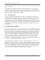
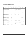
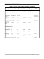
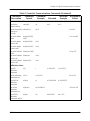
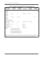
7.1.10 Fluid Characteristics Table
Table 7-1 on the next page provides help in selecting a heat exchange fluid media for your
constant temperature bath. This table provides a numerical representation of most of the
physical qualities important in making a selection. The list is not all inclusive. There may
be other useful fluids not shown in this listing.
The table includes information on a variety of fluids which are often used as heat transfer
fluid in baths. Because of the temperature range, some fluids may not be useful with your
bath.
CTR-80 User’s Manual
35
Chapter 7. General Operation
Table 2: Various Bath Fluids
Fluid (# =
Hart Part
No.)
Lower
Temper
ature
Limit*
Upper
Temperature
Limit*
Flash
Point
Viscosity
(centistokes)
Specific
Gravity
Specific Heat
(cal/g/°C)
Thermal
Conductivity
(cal/s/cm/°C)
Thermal
Expansion
(cm/cm/°C)
Halocarbon
0.8 #5019
–100°C
(v)**
70°C (e)
NONE
5.7@–50°C
0.8@40°C
0.5@70°C
1.71@40°C
0.2
0.0004
0.0011
Methanol
–96°C
(fr)
10°C (fl, cc)
12°C
1.3@–35°C
0.66@0°C
0.45@20°C
0.810@0°C
0.792@20°C
0.6
0.0005@20°C
0.0014@ 25°C
Water
0°C (fr)
95°C (b)
NONE
1@25°C
0.4@75°C
1.00
1.00
0.0014
0.0002@25°C
Ethylene
–30°C
(fr)
90°C (b)
NONE
7@0°C
2@50°C
0.7@100°C
1.05
0.8@0°C
0.001
10°C (v)
166°C (fl)
168°C
15@75°C
0.87@25°C
0.84@75°C
0.81@125°C
0.48@25°C
0.53@75°C
0.57@125°C
0.00025@25°C
0.0007@50°C
5@125°C
5@25°C
0.92@25°C
0.4
0.00028@25°C
0.00105
Glycol—
50%
Resistivity
(1012 -cm)
#5020
Mineral Oil
No.7
#5011
Silicone Oil
Type
–40°C
(v)**
130°C (fl, cc)
–30°C
(v)**
209°C (fl, cc)
Silicone Oil
Type 200.20
#5013
10°C (v)
230°C (fl, cc)
Silicone Oil
Type 200.50
#5014
30°C (v)
Silicone Oil
Type 550
70°C (v)
133°C
5@25°C
1000@25°C
10@150°C
200.05
#5010
Silicone Oil
Type
211°C
10@25°C
3@135°C
0.934@25°C
20@25°C
0.949@25°C
200.10
#5012
280°C
50@25°C
0.96@25°C
230°C (fl, cc)
232°C
300°C (fl,
oc)
80°C (v)
300°C
(fl, oc)
302°C
313°C (fl,
oc)
315°C
550°C
NONE
50@70°C
10@104°C
1.07@25°C
50@80°C
7@204°C
1.11@25°C
50@66°C
0.96@25°C
#5017
Silicone Oil
Type
0.00032@25°C
0.370@40°C
0.393@100°C
0.420@200°C
0.00034@25°C
0.4
0.00037@25°C
0.00108
1000@25°C
50@150°C
0.00107
1000@25°C
50@150°C
0.00104
1000@25°C
50@150°C
#5016
Silicone Oil
Type 710
278°C (fl, cc)
232°C
0.43@40°C
0.45@100°C
0.482@200°C
66°C (v)
0.358@40°C
0.386@100°C
0.433@200°C
0.00035@25°C
0.363@40°C
0.454@100°C
0.505@200°C
0.00035@25°C
0.34@100°C
0.0003
0.00075
100@25°C
1@150°C
0.00077
100@25°C
1@150°C
0.00095
14@204°C
100@25°C
1@150°C
210-H
Heat
Transfer Salt
#5001
180°C
(fr)
34@150°C
6.5@300°C
2.4@500°C
2.0@150°C
1.9@300°C
1.7@500°C
0.33
0.0014
0.00041
1.7 /cm3
*Limiting Factors—b - boiling point e - high evaporation fl - flash point fr - freeze point v - viscosity — Flash point test
oc = open cup cc = closed cup **Very low water solubility, ice will form as a slush from condensation below freezing.
36
CTR-80 User’s Manual
Chapter 7. General Operation
7.1.11 Limitations and Disclaimer
The information given in this manual regarding fluids is intended only to be used as a
general guide in choosing a fluid. Though every effort has been made to provide correct
information, we cannot guarantee accuracy of data or assure suitability of a fluid for a
particular application. Specifications may change and sources sometimes offer differing
information. GE cannot be liable for any personal injury or damage to equipment, product
or facilities resulting from the use of these fluids. The user of the bath is responsible for
collecting correct information, exercising proper judgment, and insuring safe operation.
Operating near the limits of certain properties such as the flash point or viscosity can
compromise safety or performance. Your company’s safety policies regarding flash points,
toxicity, and such issues must be considered.You are responsible for reading the (material
safety data sheets) and acting accordingly.
7.2 Stirring
Stirring of the bath fluid is very important for stable temperature control. The fluid must
be mixed well for good temperature uniformity and fast controller response. The stirrer is
precisely adjusted for optimum performance.
CTR-80 User’s Manual
37
Chapter 7. General Operation
7.3 Power
Power to the bath is provided by an AC mains supply. See Chapter 2, Specifications and
Environmental Conditions, for power details. Refer to and read the CAUTION at the front
of this manual concerning brownout and over voltage protection. Power to the bath passes
through a filter to prevent switching spikes from being transmitted to other equipment.
To turn on the bath switch the control panel power switch to the ON position. The stirring
motor will turn on, the LED display will begin to show the bath temperature, and the
heater will turn on or off until the bath temperature reaches the programmed set-point.
When powered on, the control panel display will briefly show a four digit number. This
number indicates the number of times power has been applied to the bath. Also briefly
displayed is data which indicates the controller hardware configuration. This data is used
in some circumstances for diagnostic purposes.
7.4 Heater
The power to the bath heater is precisely controlled by the temperature controller to
maintain a constant bath temperature. Power is controlled by periodically switching the
heater on for a certain amount of time using a solid-state relay.
The front panel LED heater mode shows the state of the heater. The indicator glows red
when the heater is on and is off when the heater is off. The indicator will pulse constantly
when the bath is maintaining a stable temperature.
38
CTR-80 User’s Manual
Chapter 7. General Operation
7.5 Refrigeration
This bath uses a two-stage refrigeration system which requires special refrigerants to
enable it to reach low temperatures. This section describes some aspects of the cooling
system and provides important information regarding refrigerants.
7.5.1 Operation
The bath controller automatically switches off cooling when the bath is operated above
50°C to protect the system from extreme pressures. The refrigeration system is also
protected by a brownout and over voltage protection device that switches off power to the
system when the line voltage is outside the safe operating range. The display indicates
“LoLinE” when this condition exists. A time delay prevents the refrigeration from
restarting for a short time after adequate line voltage has been restored.
7.5.2 Important Refrigerant Information
The refrigeration system in this bath has been designed to perform at ultra-low
temperatures. As a result, aspects of the design are uncommon and the refrigerants are
non-standard.
The system is cascaded, meaning there are two separate systems with the first one chilling
the second. This is required to reach temperatures below –40°C. Normal refrigeration does
not use a cascading technique, and many refrigeration technicians are not familiar with
such systems.
The first stage refrigerant is an HFC known as R-507. The second stage performs the
ultra-low cooling. Its refrigerant is an HFC R-508B, also known as SUVA-95.
What this means to you:
•
The cascade system is complex and its uncommon nature means that many local
refrigeration service technicians may not be able to service it. If your bath needs
service, call GE Customer Service.
•
The compressor manufacturer does not warranty their compressors when used with
non-standard refrigerants. Warranty of these compressors must be handled through
GE only. There is no other way for you to receive parts or service on your compressor.
You must receive your parts or service from GE Measurement & Control.
CTR-80 User’s Manual
39
Chapter 7. General Operation
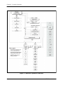
7.6 Temperature Controller
The bath temperature is controlled by a special digital temperature controller. The
controller features a 24-bit analog-to-digital converter (DAC) that gives it remarkable
accuracy and stability.
The bath temperature is monitored with a platinum resistance sensor in the control probe.
The controller uses a proportional-integral-derivative (PID) algorithm to determine how
much heat the bath needs. The bath is heated by a solid-state relay (SSR) controlled 500 W
heater. The bath is operable within the temperature range given in the specifications.
For protection against solid-state relay failure or other circuit failure, a thermocouple
cutout automatically turns off the heater anytime the bath temperature exceeds the
maximum temperature.
The controller allows the operator to set the bath temperature with high resolution, adjust
the proportional band, monitor the heater output power, and program the controller
configuration and calibration parameters. The controller may be operated in temperature
units of degrees Celsius or Fahrenheit. The controller is operated and programmed from
the front control panel using the four key switches and digital LED display. The controller
is equipped with a serial RS-232 digital interface for remote operation. Operation of the
controller using the front control panel is discussed following in Chapter 8. Operation
using the digital interfaces is discussed in Chapter 9.
When the controller is set to a new set-point the bath heats or cools to the new
temperature. Once the new temperature is reached the bath usually takes 15-20 minutes
for the temperature to settle and stabilize. There may be a small amount of overshoot or
undershoot.
40
CTR-80 User’s Manual
Chapter 8. Controller Operation
Chapter 8.
Controller Operation
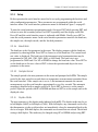
8.1 Introduction
This section discusses in detail how to operate the bath temperature controller using the
front control panel. Using the front panel key-switches and LED display, the user may
monitor the bath temperature, set the temperature set-point in degrees C or F, monitor the
heater output power, adjust the controller proportional band, and program the calibration
parameters, operating parameters, and serial interface configuration. Operation of the
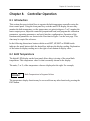
functions and parameters are shown in the flowchart in Figure 3 on the next page. This
chart may be copied for reference.
In the following discussion a button with the word SET, UP, EXIT or DOWN inside
indicates the panel button while the dotted box indicates the display reading. Explanation
of the button or display reading are to the right of each button or display value.
8.2 Bath Temperature
The digital LED display on the front panel allows direct viewing of the actual bath
temperature. This temperature value is what is normally shown on the display.
The units, C or F, of the temperature value are displayed at the right. For example,
10.00 C
Bath Temperature in Degrees Celsius
The temperature display function may be accessed from any other function by pressing the
EXIT button.
CTR-80 User’s Manual
41
Chapter 8. Controller Operation
Figure 3: Controller Operator Flowchart
42
CTR-80 User’s Manual
Chapter 8. Controller Operation
8.3 Temperature Set-point
The temperature set-point can be set to any value within the range and resolution as given
in the specifications. Be careful not to exceed the safe temperature limits of any devices
inserted into the bath.
Setting the temperature involves two steps:
1. select the set-point memory and
2. adjust the set-point value.
To protect the refrigeration system from excessive pressures, it will not operate above
50°C.
8.3.1 Programmable Set-points
The controller stores 8 set-point temperatures in memory. The set-points can be quickly
recalled to conveniently set the calibrator to a previously programmed temperature setpoint.
To set the temperature one must first select the set-point memory. This function is
accessed from the temperature display function by pressing SET. The number of the setpoint memory currently being used is shown at the left on the display followed by the
current set-point value.
10.00 C
Bath Temperature in Degrees Celsius
Access Set-point Memory
1.25.0
CTR-80 User’s Manual
Set-point Memory 1,
25¬×C Currently Use
43
Chapter 8. Controller Operation
8.3.1 Programmable Set-points (cont.)
To change the set-point memory press UP or DOWN.
4. -25.0
New Set-point Memory 4, –25
Press SET to accept the new selection and access the set-point value.
Accept Selected Set-point Memory
8.3.2 Set-point Value
The set-point value may be adjusted after selecting the set-point memory and pressing
SET.
4. -25.0
Set-point 4 Value in ¬×
If the set-point value is correct, hold EXIT to resume displaying the well temperature.
Press UP or DOWN to adjust the set-point value.
-28.00
New Set-point Value
When the desired set-point value is reached, press SET to accept the new value and access
the temperature scale units selection. If EXIT is pressed instead of SET, any changes made
to the set-point are ignored.
Accept New Set-point Value
44
CTR-80 User’s Manual
Chapter 8. Controller Operation
8.3.3 Temperature Scale Units
The temperature scale units of the controller can be set by the user to degrees Celsius (°C)
or Fahrenheit (°F). The selected units are used in displaying the well temperature, setpoint, and proportional band.
Press SET after adjusting the set-point value to change display units.
Un= C
Scale Units Currently Selected
Press UP or DOWN to change the units.
Un= F
New Units Selected
8.4 Scan
The scan rate can be set and enabled so that when the set-point is changed, the bath heats
or cools at a specified rate (degrees per minute) until it reaches the new set-point. With the
scan disabled, the bath heats or cools at the maximum possible rate.
8.4.1 Scan Control
The scan is controlled with the scan on/off function that appears in the main menu after the
set-point function.
Sc=OFF
Scan Function Off
Press UP or DOWN to toggle the scan on or off.
Sc=On
Scan Function On
Press SET to accept the present setting and continue.
Accept Scan Setting
CTR-80 User’s Manual
45
Chapter 8. Controller Operation
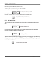
8.4.2 Scan Rate
The next function in the main menu is the scan rate. The scan rate can be set from 0.1 to
99.9°C/min. The maximum scan rate however is actually limited by the natural heating or
cooling rate of the instrument. This will be less than 10°C/min.
The scan rate function appears in the main menu after the scan control function. The scan
rate units are in degrees per minute, degrees C or F depending on the selected units.
Sr= 5.0
Scan Rate in ¬×C/Min
Press UP or DOWN to change the scan rate.
Sr= 2.0
New Scan Rate
Press SET to accept the new scan rate and continue.
Accept Scan Rate
8.5 Secondary Menu
Functions which are used less often are accessed within the secondary menu. The
secondary menu is accessed by pressing SET and EXIT simultaneously and then releasing.
The first function in the secondary menu is the heater power display. (See Figure 3 on
page 42.)
46
CTR-80 User’s Manual
Chapter 8. Controller Operation
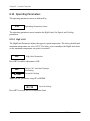
8.6 Heater Power
The temperature controller controls the temperature of the bath by pulsing the heater on
and off. The total power being applied to the heater is determined by the duty cycle or the
ratio of heater on time to the pulse cycle time. By knowing the amount of heating the user
can tell if the calibrator is heating up to the set-point, cooling down, or controlling at a
constant temperature. Monitoring the percent heater power will let the user know how
stable the bath temperature is.
The heater power display is accessed in the secondary menu. Press SET and EXIT
simultaneously and release. The heater power will be displayed as a percentage of full
power.
10.00C
Bath Temperature
Access Heater Power in Secondary Menu
SEC
12.0 P
Flashes
Heater Power in Percent
To exit out of the secondary menu, hold EXIT. To continue on to the proportional band
setting function, press EXIT momentarily or SET.
CTR-80 User’s Manual
47
Chapter 8. Controller Operation
8.7 Proportional Band
In a proportional controller such as this, the heater output power is proportional to the well
temperature over a limited range of temperatures around the set-point. This range of
temperature is called the proportional band. At the bottom of the proportional band the
heater output is 100%. At the top of the proportional band the heater output is 0. Thus as
the temperature rises the heater power is reduced, which consequently tends to lower the
temperature back down. In this way the temperature is maintained at a fairly constant
temperature.
The temperature stability of the bath and response time depend on the width of the
proportional band. If the band is too wide the temperature will deviate excessively from
the set-point due to varying external conditions. This is because the power output changes
very little with temperature and the controller cannot respond very well to changing
conditions or noise in the system. If the proportional band is too narrow, the temperature
may swing back and forth because the controller overreacts to temperature variations. For
best control stability the proportional band must be set for the optimum width. This value
is usually two to three times the largest value at which the bath temperature oscillates.
The proportional band width is set at the factory to a value between 0.5 and 1.0°C. The
proportional band width may be altered by users who desire to optimize the control
characteristics for a particular application.
The proportional band width is easily adjusted from the front panel. The width may be set
to discrete values in degrees C or F depending on the selected units. The proportional band
adjustment is be accessed within the secondary menu. Press SET and EXIT to enter the
secondary menu and show the heater power. Then press SET to access the proportional
band.
48
CTR-80 User’s Manual
Chapter 8. Controller Operation
8.7 Proportional Band (cont.)
Access Heater Power in Secondary
Menu
12.0 P
Heater Power in Percent
Access Proportional Band
ProP
Flashes “ProP‚” and the Setting
Proportional Band Setting
15.0
To change the proportional band, press UP or DOWN.
1.5
New Proportional Band Setting
To store the new setting, press SET. Press EXIT to continue without storing the new value.
Accept the New Proportional Band Setting
CTR-80 User’s Manual
49
Chapter 8. Controller Operation
8.8 Cutout
As a protection against software or hardware fault or user error, the bath is equipped with
an adjustable cutout device that shuts off power to the heater if the temperature exceeds a
set value. This protects the instrument, probes, and fluid from excessive temperatures. The
cutout temperature is programmable by the operator from the front panel of the controller.
The cutout should be set to the temperature limits of the selected fluid.
If the cutout is activated because of excessive temperature, power to the heater shuts off
and the instrument cools. The bath cools until it reaches a few degrees below the cutout
set-point temperature. At this point the cutout resets and allows normal operation.
The cutout set-point may be accessed within the secondary menu. Press SET and EXIT to
enter the secondary menu and show the heater power. Then press SET twice to access the
cutout set-point.
Access Heater Power in Secondary Menu
12.0 P
Heater Power in Percent
Access Proportional Band
Pb= 0.05C
Proportional Band Setting
Access Cutout Set-point
CO= 60C
50
Cutout Set-point
CTR-80 User’s Manual
Chapter 8. Controller Operation
8.8 Cutout (cont.)
To change the cutout set-point, press UP or DOWN.
CO= 70C
New Cutout Set-point
To accept the new cutout set-point, press SET.
Accept Cutout Set-point
The next function is the configuration menu. Press EXIT to resume displaying the
temperature.
8.9 Controller Configuration
The controller has a number of configuration and operating options and calibration
parameters which are programmable via the front panel. These are accessed from the
secondary menu after the proportional band function by pressing SET. Pressing SET again
enters the first of three sets of configuration parameters: operating parameters, serial
interface parameters, and calibration parameters. The menus are selected using the UP or
DOWN keys and then pressing SET. (See Figure 3 on page 42.)
CTR-80 User’s Manual
51
Chapter 8. Controller Operation
8.10 Operating Parameters
The operating parameters menu is indicated by,
PAr
Operating Parameters Menu
The operating parameters menu contains the High Limit, Stir Speed, and Cooling
parameters.
8.10.1 High Limit
The High Limit Parameter adjusts the upper set-point temperature. The factory default and
maximum temperature are set to 100°C. For safety, a user can adjust the High Limit down
so the maximum temperature set-point is restricted.
HL
High Limit Parameter
Press SET to enable adjustment of HL.
HL
H=100
Flashes “HL” and then Displays
the Setting
Current HL Setting
Adjust the HL parameter using UP or DOWN.
H= 90
New HL Setting
Press SET to accept the new temperature limit.
52
CTR-80 User’s Manual
Chapter 8. Controller Operation
8.10.2 Low Limit
The Low Limit (LL) Parameter adjusts the lower set-point temperature limit. The factory
default and minimum temperature are set to –90°C. For safety, a user can adjust the Low
Limit up so the minimum temperature set-point is restricted.
LL
Low Limit Parameter
Press SET to enable adjustment of LL.
LL
L=-90
Flashes “” and then Displays
the Setting
Current LL Setting
Adjust the LL parameter using UP or DOWN.
L=-20
New LL Setting
Press SET to accept the new temperature limit.
CTR-80 User’s Manual
53
Chapter 8. Controller Operation
8.11 Cooling
This menu function allows the operator to disable cooling and corresponds to the remote
cooling control function (see Table 3 on page 65). Switching the cooling off temporarily
allows the bath to heat up more quickly from a low temperature.
Cooling can be manually switched off using the cooling switch on the front panel or
automatically switched off any time the bath temperature or set-point is higher than about
35°C. As a result, cooling is ON only if the cooling function is ON, the cooling switch is
ON, and both the bath temperature and the set-point are less than about 35°C. The cooling
function is indicated by,
CooL
CooL=OFF
Flashes “CooL” and then Displays
the Setting
Current Cooling Setting
The setting may be changed using UP or DOWN and pressing SET.
CooL=On
54
New Cooling Setting
CTR-80 User’s Manual
Chapter 8. Controller Operation
8.12Serial Interface Parameters
The serial RS-232 interface parameters menu is indicated by,
SErIAL
Serial RS-232 Interface
Parameters Menu
The serial interface parameters menu contains parameters which determine the operation
of the serial interface. These controls only apply to instruments fitted with the serial
interface. The parameters in the menu are: baud rate, sample period, duplex mode, and
linefeed. Press UP to enter the menu.
8.12.1 Baud Rate
The baud rate is the first parameter in the menu. The baud rate setting determines the serial
communications transmission rate. The baud rate parameter is indicated by,
bAUd
2400 b
Flashes ”bAUd” and then Displays
the Setting
Current Baud Rate
The baud rate of the serial communications may be programmed to 300, 600, 1200, 2400,
4800, or 9600 baud. Use UP or DOWN to change the baud rate value.
4800 b
New Baud Rate
Press SET to set the baud rate to the new value or EXIT to abort the operation and skip to
the next parameter in the menu.
CTR-80 User’s Manual
55
Chapter 8. Controller Operation
8.12.2 Sample Period
The sample period is the next parameter in the serial interface parameter menu. It is the
time period in seconds between temperature measurements transmitted from the serial
interface. If the sample rate is set to 5, the instrument transmits the current measurement
over the serial interface approximately every five seconds. The automatic sampling is
disabled with a sample period of 0. The sample period is indicated by
SPEr
Flashes “SPEr” and then Displays
the Setting
SP=1
Current Sample Period (Seconds)
Adjust the value with UP or DOWN and then use SET to store the sample rate to the
displayed value. EXIT does not store the new value.
SP= 50
56
New Sample Period
CTR-80 User’s Manual
Chapter 8. Controller Operation
8.12.3 Duplex Mode
The next parameter is the duplex mode. The duplex mode may be set to full duplex or half
duplex. With full duplex, any commands received by the calibrator via the serial interface
are immediately echoed or transmitted back to the device of origin. With half duplex the
commands are executed but not echoed. The duplex mode parameter is indicated by,
dUPL
d=FULL
Flashes ”dUPL” and then
Displays the Setting
Current Duplex Mode Setting
The mode may be changed using UP or DOWN and pressing SET.
d=HALF
New Duplex Mode Setting
8.12.3a Linefeed
The final parameter in the serial interface menu is the linefeed mode. This parameter
enables (on) or disables (off) transmission of a linefeed character (LF, ASCII 10) after
transmission of any carriage-return. The linefeed parameter is indicated by,
LF
LF= On
Flashes ”LF‚” and then Displays
the Setting
Current Linefeed Setting
The mode may be changed using UP or DOWN and pressing SET.
LF= OFF
CTR-80 User’s Manual
New Linefeed Setting
57
Chapter 8. Controller Operation
8.13Calibration Parameters
The operator of the CTR –80 controller has access to the Hard Cutout and a number of the
bath calibration constants, namely, R0, ALPHA, DELTA, and BETA. These values are set
at the factory and should not be altered. The correct values are important to the accuracy
and proper and safe operation of the bath. Access to these parameters is available to the
user only so that in the event that the controller memory fails, the user may restore these
values to the factory settings. The user should have a list of these constants and their
settings with the manual.
CAUTION!
DO NOT change the values of the bath calibration constants from the
factory set values. The correct setting of these parameters is
important to the safety and proper operation of the bath.
The calibration parameters menu is indicated by:
CAL
Calibration Parameters Menu
Press SET five times to enter the menu.
The calibration parameters R0, ALPHA, DELTA, and BETA characterize the resistancetemperature relationship of the platinum control sensor. These parameters may be adjusted
by an experienced user to improve the accuracy of the bath.
58
CTR-80 User’s Manual
Chapter 8. Controller Operation
8.13.1 Hard Cutout
This parameter is the temperature above which the unit shuts down automatically. The
parameter is set at the factory to approximately 120°C and can be changed only through
the variable resistor. This parameter cannot be changed through the instrument menu or
the communications port and is user settable.
8.13.2 R0
This probe parameter refers to the resistance of the control probe at 0°C. The value of this
parameter is set at the factory for best instrument accuracy.
8.13.3 ALPHA
This probe parameter refers to the average sensitivity of the probe between 0 and 100°C.
The value of this parameter is set at the factory for best instrument accuracy.
8.13.4 DELTA
This probe parameter characterizes the curvature of the resistance-temperature
relationship of the sensor. The value of this parameter is set at the factory for best
instrument accuracy.
8.13.5 BETA
This probe parameter characterizes the low temperatures. The value of this parameter is
set at the factory for best instrument accuracy.
CTR-80 User’s Manual
59
Chapter 8. Controller Operation
[no content intended for this page - proceed to next page]
60
CTR-80 User’s Manual
Chapter 9. Digital Communications Interface
Chapter 9.
Digital Communications Interface
9.1 Introduction
The CTR –80 Bath calibrator is capable of communicating with and being controlled by
other equipment through the digital serial interface. With a digital interface the instrument
may be connected to a computer or other equipment. This allows the user to set the setpoint temperature, monitor the temperature, and access any of the other controller
functions, all using remote communications equipment. Communications commands are
summarized in Table 3 on page 65.
9.2 Serial Communications
The bath is installed with an RS-232 serial interface that allows serial digital
communications over fairly long distances. With the serial interface the user may access
any of the functions, parameters and settings discussed in Chapter 8, with the exception of
the baud rate setting.
CTR-80 User’s Manual
61
Chapter 9. Digital Communications Interface
9.3 Wiring
The serial communications cable attaches to the calibrator through the DB-9 connector at
the back of the instrument. Figure 4 below shows the pin-out of this connector and
suggested cable wiring. To eliminate noise, the serial cable should be shielded with low
resistance between the connector (DB-9) and the shield. If the unit is used in a heavy
industrial setting, the serial cable must be limited to ONE METER in length.
Figure 4: RS-232 Cable Wiring for
IBM PC and Compatibles
62
CTR-80 User’s Manual
Chapter 9. Digital Communications Interface
9.3.1 Setup
Before operation the serial interface must first be set up by programming the baud rate and
other configuration parameters. These parameters are programmed within the serial
interface menu. The serial interface parameters menu is outlined in Figure 3 on page 42.
To enter the serial parameter programming mode, first press EXIT while pressing SET, and
release to enter the secondary menu. Press SET repeatedly until the display reads PAr.
Press UP until the serial interface menu is indicated with SErIAL. Finally, press SET to
enter the serial parameter menu. In the serial interface parameters menu are the baud rate,
the sample rate, the duplex mode, and the linefeed parameter.
9.3.1a
Baud Rate
The baud rate is the first parameter in the menu. The display prompts with the baud rate
parameter by showing bAUd. Press SET to choose to set the baud rate. The current baud
rate value is displayed. The baud rate of the instrument serial communications may be
programmed to 300, 600, 1200, 2400, 4800, or 9600 baud. The baud rate is preprogrammed to 2400 baud. Use UP or DOWN to change the baud rate value. Press SET to
set the baud rate to the new value or EXIT to abort the operation and skip to the next
parameter in the menu.
9.3.1b
Sample Period
The sample period is the next parameter in the menu and prompted with SPEr. The sample
period is the time period in seconds between temperature measurements transmitted from
the serial interface. If the sample rate is set to 5, the instrument transmits the current
measurement over the serial interface approximately every five seconds. The automatic
sampling is disabled with a sample period of 0. Press SET to choose to set the sample
period. Adjust the period with UP or DOWN and then use SET to set the sample rate to the
displayed value.
9.3.1c
Duplex Mode
The next parameter is the duplex mode indicated with dUPL. The duplex mode may be set
to half duplex (HALF) or full duplex (FULL). With full duplex, any commands received by
the thermometer via the serial interface are immediately echoed or transmitted back to the
device of origin. With half duplex, the commands are executed but not echoed. The default
setting is half duplex. The mode may be changed using UP or DOWN and pressing SET.
CTR-80 User’s Manual
63
Chapter 9. Digital Communications Interface
9.3.1d
Linefeed
The final parameter in the serial interface menu is the linefeed mode. This parameter
enables (On) or disables (OFF) transmission of a linefeed character (LF, ASCII 10) after
transmission of any carriage-return. The default setting is linefeed off. The mode may be
changed using UP or DOWN and pressing SET.
9.3.2 Serial Operation
Once the cable has been attached and the interface set up properly, the controller will
immediately begin transmitting temperature readings at the programmed rate. The serial
communications uses 8 data bits, one stop bit, and no parity. The set-point and other
commands may be sent via the serial interface to set the temperature set-point and view or
program the various parameters. The interface commands are discussed on the next page.
All commands are ASCII character strings terminated with a carriage-return character
(CR, ASCII 13).
9.4 Interface Commands
The various commands for accessing the calibrator functions via the digital interfaces are
listed in this section (see Table 9-1 on the next page). These commands are used with the
RS-232 serial interface. The commands are terminated with a carriage-return character.
The interface makes no distinction between upper and lower case letters, hence, either
may be used. Commands may be abbreviated to the minimum number of letters which
determines a unique command. A command may be used to either set a parameter or
display a parameter, depending on whether or not a value is sent with the command
following a “=” character. For example, “s” <CR> will return the current set-point and
“s=150.0” <CR> will set the set-point to 150.0 degrees.
In the following list of commands, characters or data within brackets, “[” and “]”, are
optional for the command. A slash, “/”, denotes alternate characters or data. Numeric data,
denoted by “n”, may be entered in decimal or exponential notation. Characters are shown
in lower case although upper case may be used. Spaces may be added within command
strings and will simply be ignored. Backspace (BS, ASCII 8) may be used to erase the
previous character. A terminating CR is implied with all commands.
64
CTR-80 User’s Manual
Chapter 9. Digital Communications Interface
9.4 Interface Commands (cont.)
Table 3: Controller Communications Commands
Command
Command
Returned
Format
Example
Returned
Example
Command
Description
Acceptable
Values
Display Temperature
Read current setpoint
s[etpoint]
s
Set current setpoint to n
s[etpoint]=n
s=80.00
set: 999.99 {C
or F}
set: 90.00 C
Instrument
Range
Read temperature t[emperature]
t
t: 999.99 {C or
F}
t: 55.6 C
Read temperature u[nits]
units
u
u: x
u: C
Set temperature
units
u[nits]=c/f
Set temperature
units to Celsius
u[nits]=c
u=c
Set temperature u[nits]=f
units to Fahrenheit
u=f
Read scan mode
sc[an]
sc
Set scan mode
sc[an]=on/off
sc=on
Read scan rate
sr[ate]
sr
Set scan rate
sr[ate]=n
sr=1.1
CTR-80 User’s Manual
C or F
scan: {ON or
OFF}
scan:ON
ON or OFF
srat: 99.9 {C or srat:12.4C/min
F}/min
0.1 to 99.9
65
Chapter 9. Digital Communications Interface
Table 3: Controller Communications Commands (Continued)
Command
Command
Command
Returned Acceptable
Description
Format
Example
Returned
Example
Values
Secondary Menu
Read proportional pr[opband]
band
setting
pr
Set proportional
band to n
pr[opband]=n
pr=8.83
Read cut-out
setting
cu[tout]
cu
pb: 999.9
pb: 15.9
Depends on
Configuration
cu:9999 {C or
F}
cu:105 C, in
Set cut-out setting cu[tout]=n
to n degrees
cu-95
Read heater
power
po
po: 999.9
po: 1.0
hl:999
hl:126
po[wer]
25 to 115°C
(duty cycle)
Configuration Menu
Operating Parameters Menu
Read high limit
hl
hl
Set high limit
hl=n
hl=90
Read low limit
ll
ll
Set low limit
ll=n
ll=-90
Read cooling
setting
co[ol]
co
Set cooling setting co[ol]=on/of[f]
66
co=on
25 to 100
ll:999
ll:-90
cool: {ON or
OFF}
cool: ON
–90 to 25
ON or OFF
CTR-80 User’s Manual
Chapter 9. Digital Communications Interface
Table 3: Controller Communications Commands (Continued)
Command
Command
Command
Returned Acceptable
Description
Format
Example
Returned
Example
Values
Serial Interface Menu
Read serial
sample setting
sa[mple]
Set serial sampling sa[mple]=n
setting to n
seconds
sa
sa: 9
sa: 1
sa=0
Set serial duplex
mode
du[plex]=f[ull]/
h[alf]
Set serial duplex
mode to full
du[plex]=f[ull]
du=f
Set serial duplex
mode to half
du[plex]=h[alf]
du=h
0 to 999
FULL or HALF
Set serial linefeed lf[eed]=on/of[f]
mode
ON or OFF
Set serial linefeed lf[eed]=on
mode to on
lf=on
Set serial linefeed lf[eed]=of[f]
mode to off
lf=of
Calibration Menu
Read R0
calibration
parameter
r[0]
Set R0 calibration r[0]=n
parameter to n
r
al[pha]
al
Set ALPHA
calibration
parameter to n
al[pha]=n
al=0.0038433
CTR-80 User’s Manual
r0: 100.578
r=100.324
Read ALPHA
calibration
parameter
de[lta]
Read DELTA
calibration
parameter de[lta]
r0: 999.999
de
90 to 110
al: 9.9999999
al: 0.0038573
.002 to 0.005
de:9.99999
de: 1.507
67
Chapter 9. Digital Communications Interface
Table 3: Controller Communications Commands (Continued)
Command
Command
Command
Returned Acceptable
Description
Format
Example
Returned
Example
Values
Set DELTA
calibration
parameter
de[lta]=n
de=1.3742
Read BETA
calibration
parameter
be[ta]
be
Set BETA
calibration
parameter
be[ta]=n
be=0.342
0–3.0
be:99.999
be:03427
–20 to 20
Functions Not on Menu
Read firmware
version number
*ver[sion]
*ver
ver.9999,9.99
Read structure of
all commands
h[elp]
h
list of
commands
all
list of
parameters
Read all operating all
parameters
Legend:
ver.7103,2.00
[] Optional Command data
{} Returns either information
n Numeric data supplied by user
9 Numeric data returned to user
x Character data returned to user
Note: When DUPLEX is set to FULL and a command is sent to READ, the command is returned followed by
a carriage return and linefeed. Then the value is returned as indicated in the RETURNED column.
68
CTR-80 User’s Manual
Chapter 10. Calibration Procedure
Chapter 10. Calibration Procedure
10.1Introduction
Calibration of this instrument should be performed at regularly scheduled intervals by
qualified authorized personnel in accordance with your company’s policy. Following is the
recommended procedure for calibrating this instrument.
10.2Calibration Equipment
Calibration requires a standard thermometer that is adequately accurate and fits properly
into one of the reference holes in the block. Recommended equipment includes a
laboratory grade PRT with a length of 30 to 300 mm (9 to 12 inches) and a diameter of
4.76 or 6.35 mm (3/16 or 1/4 inches). The combined accuracy of the PRT and the readout
which used to display the temperature should be 0.025°C or better.
10.3Calibration
The accuracy of the instrument over the full range is determined by the values of the
calibration parameters R0, ALPHA, DELTA, and BETA. The calibration procedure
involves measuring the error between the instrument and the reference thermometer at
several temperature throughout the range and adjusting the calibration parameters as
necessary to reduce the errors to within acceptable limits. The stated accuracy of the
instrument can be found in the specification table in Chapter 2. Because of the way the
calibration parameters affect the temperature, the simplest way to proceed is to measure
the errors at 0°C, 100°C, 50°C, and –70°C and adjust R0, ALPHA, DELTA, and BETA at
each point respectively. Be aware that you must use the appropriate fluid at each
temperature.
CTR-80 User’s Manual
69
Chapter 10. Calibration Procedure
10.3 Calibration (cont.)
Follow these steps:
•
Set the set-point to 0°C and allow adequate time for the bath to reach this temperature
and stabilize. Adjust the R0 calibration parameter (see page 59) to make the bath
temperature as measured with the standard thermometer match the set-point. The
approximate ratio between a change in R0 and a change in temperature at 0°C is about
0.4 to 1. For example, if the bath temperature is high by 0.1°C at 0°C, then decrease
R0 by 0.04.
•
Set the set-point to 100°C and allow adequate time for the bath to reach this
temperature and stabilize. Adjust the ALPHA calibration parameter (see page 59) to
make the bath temperature as measured with the standard thermometer match the setpoint. The approximate ratio between a change in ALPHA and a change in
temperature at 100°C is about 0.00004 to 1. For example, if the bath temperature is
high by 0.1°C at 100°C, then decrease ALPHA by 0.000004.
•
Set the set-point to 50°C and allow adequate time for the bath to reach this
temperature and stabilize. Adjust the DELTA calibration parameter (see page 59) to
make the bath temperature as measured with the standard thermometer match the setpoint. The approximate ratio between a change in DELTA and a change in temperature
at 50°C is about 4.0 to 1. For example, if the bath temperature is high by 0.1°C at
50°C, then decrease DELTA by 0.4.
•
Set the set-point to –70°C and allow adequate time for the bath to reach this
temperature and stabilize. Adjust the BETA calibration parameter (see page 59) to
make the bath temperature as measured with the standard thermometer match the setpoint. The approximate ratio between a change in BETA and a change in temperature
at –70°C is about –1.0 to 1. For example, if the bath temperature is high by 0.1°C at
–70°C then increase BETA by 0.1.
70
CTR-80 User’s Manual
Chapter 11. Maintenance
Chapter 11. Maintenance
11.1Bath Maintenance
•
The calibration instrument has been designed with the utmost care. Ease of operation
and simplicity of maintenance have been a central theme in the product development.
Therefore, with proper care the instrument should require very little maintenance.
Avoid operating the instrument in dirty or dusty environments.
•
If the outside of the bath becomes soiled, it may be wiped clean with a damp cloth and
mild detergent. Do not use harsh chemicals on the surface which may damage the
paint.
•
Periodically check the fluid level in the bath to ensure that the level has not dropped.
A drop in the fluid level affects the stability of the bath. Changes in fluid level are
dependent upon several factors specific to the environment in which the equipment is
used. A schedule cannot be outlined to meet each environmental setting. Therefore,
the first year, the bath should be checked weekly with notes kept as to changes in bath
fluid. After the first year, the user can set up a maintenance schedule based on the data
specific to the application.
•
Heat transfer medium lifetime is dependent upon the type of medium and the
environment. The fluid should be checked at least every month for the first year and
regularly thereafter. This fluid check provides a baseline for knowledge of bath
operation with clean, usable fluid. Once some fluids have become compromised, the
breakdown can occur rapidly. Particular attention should be paid to the viscosity of the
fluid. A significant change in the viscosity can indicate that the fluid is contaminated,
being used outside of its temperature limits, contains ice particles, or is close to a
chemical break-down. Once data has been gathered, a specific maintenance schedule
can be outline for the instrument. Refer to Chapter 7, General Operation, for more
information about the different types of fluids used in calibration baths.
•
If a hazardous material is spilt on or inside the equipment, the user is responsible for
taking the appropriate decontamination steps as outlined by the national safety council
with respect to the material. MSDS sheets applicable to all fluids used in the baths
should be kept in close proximity to the instrument.
CTR-80 User’s Manual
71
Chapter 11. Maintenance
11.1 Bath Maintenance (cont.)
•
If the mains supply cord becomes damaged, replace it with a cord with the appropriate
gauge wire for the current of the bath. If there are any questions, call GE Customer
Service for more information.
•
Before using any cleaning or decontamination method except those recommended by
GE, users should check with GE Customer Service to be sure that the proposed
method will not damage the equipment.
•
The condensing coil should be cleaned regularly. Inspect the coil through the vented
rear panel. If any dust or dirt accumulation is visible, remove the rear panel to clean
out the dust or dirt. Use a vacuum with a brush to remove the dirt. Do not use
compressed air as it might drive the dirt between the fins where it may become lodged
preventing airflow.
•
If the instrument is used in a manner not in accordance with the equipment design, the
operation of the bath may be impaired or safety hazards may arise.
72
CTR-80 User’s Manual
Chapter 12. Troubleshooting
Chapter 12. Troubleshooting
12.1Introduction
If problems arise while operating the CTR –80, this section provides some suggestions
that may help you solve the problem. A wiring diagram is also included.
12.2Troubleshooting
Below are several situations that may arise followed by suggested actions to take for
fixing the problem.
Incorrect Temperature Reading
•
Power the unit on and watch the display. If the first number displayed is less than
“-0005-”, the unit has been reinitialized. The unit needs to be reprogrammed for R0,
ALPHA, DELTA, and BETA. These numbers can be found on the Report of
Calibration that was shipped with the unit.
The Unit Heats Slowly
•
Check the Scan and Scan Rate settings. The Scan may be on with the Scan Rate set
low.
If the display flashes any of the following:
“err 1" - This error means there is a RAM error
“err 2" - This error means there is a NVRAM error
“err 3" - This error means there is a RAM error
“err 4" - This error means there is an ADC set up error
“err 5" - This error means there is an ADC ready error
“err 6" - This error means there is a SENSOR error
“err 7" - This error means there is a HtrCTL error
•
Cycle the power off and on again. If the unit repeats the error code, contact GE
Customer Support for a return authorization and for assistance.
CTR-80 User’s Manual
73
Chapter 12. Troubleshooting
12.2 Troubleshooting (cont.)
The bath does not turn on
•
If a fault condition exists upon application of power, the bath will not energize.
•
This bath needs to be plugged into the line voltage for at least 2 minutes before turning
power on. This is only necessary for the first time that the bath is energized or when it
is moved from one location to another.
•
If a High/Low voltage condition exists for longer than 5 seconds, the compressor will
be de-energized. The controller display will flash “Lo LinE” on and off while the
condition exists.
•
Re-energization is automatic upon correction of the fault condition and after a delay
cycle of about 2 minutes.
High and Low Voltage Protection at 115 VAC
Voltage Cutout: ±12.5% (101 - 129 VAC)
Voltage Cut-In: ±7.5% (106 - 124 VAC)
High and Low Voltage Protection at 230 VAC
Voltage Cutout: ±12.5% (203 - 257 VAC)
Voltage Cut-In: ±7.5% (213 - 247 VAC)
•
See the Caution in the front of this manual for additional information.
74
CTR-80 User’s Manual
Chapter 12. Troubleshooting
12.3CE Comments
12.3.1 EMC Directive
This instrument has been tested to meet the European Electromagnetic Compatibility
Directive (EMC Directive, 89/336/EEC). The Declaration of Conformity for your
instrument lists the specific standards to which the unit was tested.
12.3.2 Low Voltage Directive (Safety)
In order to comply with the European Low Voltage Directive (73/23/EEC), this instrument
has been designed to meet the IEC 1010-1 (EN 61010-1) and IEC 1010-2-010 (EN 610102-010) standards.
CTR-80 User’s Manual
75
Chapter 12. Troubleshooting
[no content intended for this page - proceed to next page]
76
CTR-80 User’s Manual
Warranty
Warranty
Each instrument manufactured by GE Sensing is warranted to be free from defects in
material and workmanship. Liability under this warranty is limited to restoring the
instrument to normal operation or replacing the instrument, at the sole discretion of GE
Sensing. Fuses and batteries are specifically excluded from any liability. This warranty is
effective from the date of delivery to the original purchaser. If GE Sensing determines that
the equipment was defective, the warranty period is:
•
one year for general electronic failures of the instrument
•
one year for mechanical failures of the sensor
If GE Sensing determines that the equipment was damaged by misuse, improper
installation, the use of unauthorized replacement parts, or operating conditions outside the
guidelines specified by GE Sensing, the repairs are not covered under this warranty.
The warranties set forth herein are exclusive and are in lieu of all other
warranties whether statutory, express or implied (including warranties or
merchantability and fitness for a particular purpose, and warranties arising
from course of dealing or usage or trade).
CTR-80 User’s Manual
77
Return Policy
Return Policy
If a GE Sensing instrument malfunctions within the warranty period, the following
procedure must be completed:
1. Notify GE Sensing, giving full details of the problem, and provide the model number
and serial number of the instrument. If the nature of the problem indicates the need for
factory service, GE Sensing will issue a RETURN AUTHORIZATION number (RA),
and shipping instructions for the return of the instrument to a service center will be
provided.
2. If GE Sensing instructs you to send your instrument to a service center, it must be
shipped prepaid to the authorized repair station indicated in the shipping instructions.
3. Upon receipt, GE Sensing will evaluate the instrument to determine the cause of the
malfunction.
Then, one of the following courses of action will then be taken:
•
If the damage is covered under the terms of the warranty, the instrument will be
repaired at no cost to the owner and returned.
•
If GE Sensing determines that the damage is not covered under the terms of the
warranty, or if the warranty has expired, an estimate for the cost of the repairs at
standard rates will be provided. Upon receipt of the owner’s approval to proceed, the
instrument will be repaired and returned.
78
CTR-80 User’s Manual
Customer Support Centers
U.S.A.
For Sales and Services
(Repair/Calibration):
GE Measurement & Control
St Marys Center
967 Windfall Road
St Marys, Pennsylvania 15857
U.S.A.
T: 814-834-9140
F: 814-781-7969
[email protected]
U.S.A.
For Technical Support:
The Boston Center
1100 Technology Park Drive
Billerica, MA 01821
U.S.A.
T: 800-833-9438 (toll-free)
T: 978-437-1242
E-mail: [email protected]
Europe, Asia and Middle East
Sales and Service:
GE Sensing & Inspection Technologies
GmbH
Sinsheimer Strasse 6
D-75179 Pforzheim
Germany
T: +49(0)7231-14335 0
F: +49(0)7212 391 035
E-mail: [email protected]
China:
GE Sensing & Inspection Technologies
Building 10, Jintong International
Industrial Park
No. 8 Xihu Road, Wujin High-Tech
Industrial Zone
Changzhou, China 213164
T:+86 519 8831 8080 ext. 50087
F:+86 519 8831 2601
Brazil
Sales and Service:
GE Measurement & Control
Avenida Maria Coelho Aguiar, 215
Bloco C, 6º andar
Jd. São Luiz - São Paulo - SP
05804-900 - Brasil
T +55 11 3614 1876
F +55 11 3614 1799
E [email protected]
S www.ge-mcs.com./pt
www.ge-mcs.com/en/about-us/quality.html
www.ge-mcs.com
©2013 General Electric Company. All rights reserved.
Technical content subject to change without notice.
M4336 Rev. D