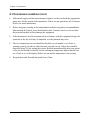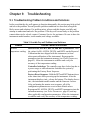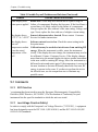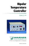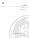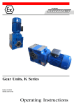
1
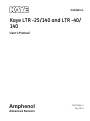
Validation Kaye LTR -25/140 and LTR -40/ 140 User’s Manual Amphenol Advanced Sensors M4374 Rev. E May 2014 Kaye LTR -25/140 and LTR -40/ 140 Memory Card for Data Backup User’s Manual M4374 Rev. E May 2014 Amphenol Advanced Sensors ©2014 Amphenol Thermometrics, Inc. All rights reserved. Technical content subject to change without notice. Contents Chapter 1. Before You Start 1.1 Symbols Used . . . . . . . . . . . . . . . . . . . . . . . . . . . . . . . . . . . . . . . . . . . . . . . . . . . . . . . . . . . . . . 1 1.2 Safety Information . . . . . . . . . . . . . . . . . . . . . . . . . . . . . . . . . . . . . . . . . . . . . . . . . . . . . . . . . . . 3 1.2.1 Warnings . . . . . . . . . . . . . . . . . . . . . . . . . . . . . . . . . . . . . . . . . . . . . . . . . . . . . . . . . . . . . 3 1.2.1 Cautions . . . . . . . . . . . . . . . . . . . . . . . . . . . . . . . . . . . . . . . . . . . . . . . . . . . . . . . . . . . . . 6 1.2.1 Customer Service Information . . . . . . . . . . . . . . . . . . . . . . . . . . . . . . . . . . . . . . . . . . . . 7 Chapter 2. Specifications and Environmental Conditions 2.1 Introduction . . . . . . . . . . . . . . . . . . . . . . . . . . . . . . . . . . . . . . . . . . . . . . . . . . . . . . . . . . . . . . . . 9 2.2 Specifications . . . . . . . . . . . . . . . . . . . . . . . . . . . . . . . . . . . . . . . . . . . . . . . . . . . . . . . . . . . . . . 10 2.2.1 Range . . . . . . . . . . . . . . . . . . . . . . . . . . . . . . . . . . . . . . . . . . . . . . . . . . . . . . . . . . . . . . 10 2.2.2 Accuracy. . . . . . . . . . . . . . . . . . . . . . . . . . . . . . . . . . . . . . . . . . . . . . . . . . . . . . . . . . . . 10 2.2.3 Stability. . . . . . . . . . . . . . . . . . . . . . . . . . . . . . . . . . . . . . . . . . . . . . . . . . . . . . . . . . . . . 10 2.2.4 Well to Well Uniformity (calibration wells) . . . . . . . . . . . . . . . . . . . . . . . . . . . . . . . . . 10 2.2.5 Well Depth . . . . . . . . . . . . . . . . . . . . . . . . . . . . . . . . . . . . . . . . . . . . . . . . . . . . . . . . . . 10 2.2.6 Heating Time . . . . . . . . . . . . . . . . . . . . . . . . . . . . . . . . . . . . . . . . . . . . . . . . . . . . . . . . 10 2.2.7 Cooling Time . . . . . . . . . . . . . . . . . . . . . . . . . . . . . . . . . . . . . . . . . . . . . . . . . . . . . . . . 10 2.2.8 Test Wells . . . . . . . . . . . . . . . . . . . . . . . . . . . . . . . . . . . . . . . . . . . . . . . . . . . . . . . . . . . 11 2.2.9 Resolution. . . . . . . . . . . . . . . . . . . . . . . . . . . . . . . . . . . . . . . . . . . . . . . . . . . . . . . . . . . 11 2.2.10 Display . . . . . . . . . . . . . . . . . . . . . . . . . . . . . . . . . . . . . . . . . . . . . . . . . . . . . . . . . . . . . 11 2.2.11 Size . . . . . . . . . . . . . . . . . . . . . . . . . . . . . . . . . . . . . . . . . . . . . . . . . . . . . . . . . . . . . . . . 11 2.2.12 Weight. . . . . . . . . . . . . . . . . . . . . . . . . . . . . . . . . . . . . . . . . . . . . . . . . . . . . . . . . . . . . . 11 2.2.13 Power . . . . . . . . . . . . . . . . . . . . . . . . . . . . . . . . . . . . . . . . . . . . . . . . . . . . . . . . . . . . . . 11 2.2.14 Operating Range . . . . . . . . . . . . . . . . . . . . . . . . . . . . . . . . . . . . . . . . . . . . . . . . . . . . . . 11 2.2.15 Controller . . . . . . . . . . . . . . . . . . . . . . . . . . . . . . . . . . . . . . . . . . . . . . . . . . . . . . . . . . . 11 2.2.16 Safety . . . . . . . . . . . . . . . . . . . . . . . . . . . . . . . . . . . . . . . . . . . . . . . . . . . . . . . . . . . . . . 11 2.2.17 Fault Protection . . . . . . . . . . . . . . . . . . . . . . . . . . . . . . . . . . . . . . . . . . . . . . . . . . . . . . 11 2.2.18 Fuses . . . . . . . . . . . . . . . . . . . . . . . . . . . . . . . . . . . . . . . . . . . . . . . . . . . . . . . . . . . . . . . 12 2.2.19 Transfer Calibration Accuracy . . . . . . . . . . . . . . . . . . . . . . . . . . . . . . . . . . . . . . . . . . . 12 2.3 Environmental Conditions . . . . . . . . . . . . . . . . . . . . . . . . . . . . . . . . . . . . . . . . . . . . . . . . . . . . 13 2.3.1 Customer Site Assistance . . . . . . . . . . . . . . . . . . . . . . . . . . . . . . . . . . . . . . . . . . . . . . . 13 Kaye LTR -25/140 and LTR -40/140 User’s Manual iii Contents Chapter 3. Quick Start 3.1 Unpacking . . . . . . . . . . . . . . . . . . . . . . . . . . . . . . . . . . . . . . . . . . . . . . . . . . . . . . . . . . . . . . . . 15 3.2 Setup. . . . . . . . . . . . . . . . . . . . . . . . . . . . . . . . . . . . . . . . . . . . . . . . . . . . . . . . . . . . . . . . . . . . . 15 3.3 Power . . . . . . . . . . . . . . . . . . . . . . . . . . . . . . . . . . . . . . . . . . . . . . . . . . . . . . . . . . . . . . . . . . . . 16 3.4 Setting the Temperature . . . . . . . . . . . . . . . . . . . . . . . . . . . . . . . . . . . . . . . . . . . . . . . . . . . . . . 16 Chapter 4. Parts and Controls 4.1 Rear Panel . . . . . . . . . . . . . . . . . . . . . . . . . . . . . . . . . . . . . . . . . . . . . . . . . . . . . . . . . . . . . . . . 17 4.2 Front Panel . . . . . . . . . . . . . . . . . . . . . . . . . . . . . . . . . . . . . . . . . . . . . . . . . . . . . . . . . . . . . . . . 19 4.3 Constant Temperature Block Assembly. . . . . . . . . . . . . . . . . . . . . . . . . . . . . . . . . . . . . . . . . . 21 4.3.1 Constant Temperature Block . . . . . . . . . . . . . . . . . . . . . . . . . . . . . . . . . . . . . . . . . . . . 21 Chapter 5. General Operation 5.1 Calibrator Setup . . . . . . . . . . . . . . . . . . . . . . . . . . . . . . . . . . . . . . . . . . . . . . . . . . . . . . . . . . . . 23 5.2 Switching Voltage Operation . . . . . . . . . . . . . . . . . . . . . . . . . . . . . . . . . . . . . . . . . . . . . . . . . . 23 5.3 Setting the Temperature . . . . . . . . . . . . . . . . . . . . . . . . . . . . . . . . . . . . . . . . . . . . . . . . . . . . . . 24 5.4 Calibrating Sensors . . . . . . . . . . . . . . . . . . . . . . . . . . . . . . . . . . . . . . . . . . . . . . . . . . . . . . . . . 24 iv Kaye LTR -25/140 and LTR -40/140 User’s Manual Contents Chapter 6. Controller Operation 6.1 Introduction . . . . . . . . . . . . . . . . . . . . . . . . . . . . . . . . . . . . . . . . . . . . . . . . . . . . . . . . . . . . . . . 27 6.2 Well Temperature . . . . . . . . . . . . . . . . . . . . . . . . . . . . . . . . . . . . . . . . . . . . . . . . . . . . . . . . . . . 27 6.3 Reset Cutout . . . . . . . . . . . . . . . . . . . . . . . . . . . . . . . . . . . . . . . . . . . . . . . . . . . . . . . . . . . . . . . 28 6.4 Temperature Set-point . . . . . . . . . . . . . . . . . . . . . . . . . . . . . . . . . . . . . . . . . . . . . . . . . . . . . . . 30 6.4.1 Programmable Set-points (Set-point Memory) . . . . . . . . . . . . . . . . . . . . . . . . . . . . . . 30 6.4.2 Set-point Value . . . . . . . . . . . . . . . . . . . . . . . . . . . . . . . . . . . . . . . . . . . . . . . . . . . . . . . 31 6.5 Set-point Resistance . . . . . . . . . . . . . . . . . . . . . . . . . . . . . . . . . . . . . . . . . . . . . . . . . . . . . . . . . 31 6.6 Ramp and Soak Program Menu . . . . . . . . . . . . . . . . . . . . . . . . . . . . . . . . . . . . . . . . . . . . . . . . 32 6.6.1 Number of Program Set-points. . . . . . . . . . . . . . . . . . . . . . . . . . . . . . . . . . . . . . . . . . . 32 6.6.2 Set-points . . . . . . . . . . . . . . . . . . . . . . . . . . . . . . . . . . . . . . . . . . . . . . . . . . . . . . . . . . . 33 6.6.3 Program Soak Time . . . . . . . . . . . . . . . . . . . . . . . . . . . . . . . . . . . . . . . . . . . . . . . . . . . 34 6.6.4 Program Function Mode. . . . . . . . . . . . . . . . . . . . . . . . . . . . . . . . . . . . . . . . . . . . . . . . 34 6.6.5 Program Control . . . . . . . . . . . . . . . . . . . . . . . . . . . . . . . . . . . . . . . . . . . . . . . . . . . . . . 36 6.7 Secondary Menu . . . . . . . . . . . . . . . . . . . . . . . . . . . . . . . . . . . . . . . . . . . . . . . . . . . . . . . . . . . 37 6.8 Heating Power . . . . . . . . . . . . . . . . . . . . . . . . . . . . . . . . . . . . . . . . . . . . . . . . . . . . . . . . . . . . . 37 6.9 Proportional Band . . . . . . . . . . . . . . . . . . . . . . . . . . . . . . . . . . . . . . . . . . . . . . . . . . . . . . . . . . 38 6.10Cutout. . . . . . . . . . . . . . . . . . . . . . . . . . . . . . . . . . . . . . . . . . . . . . . . . . . . . . . . . . . . . . . . . . . . 40 6.11Controller Configuration . . . . . . . . . . . . . . . . . . . . . . . . . . . . . . . . . . . . . . . . . . . . . . . . . . . . . 42 6.11.1 Probe Parameters . . . . . . . . . . . . . . . . . . . . . . . . . . . . . . . . . . . . . . . . . . . . . . . . . . . . . 42 6.11.2 Operating Parameters . . . . . . . . . . . . . . . . . . . . . . . . . . . . . . . . . . . . . . . . . . . . . . . . . . 43 6.11.3 Serial Interface Parameters. . . . . . . . . . . . . . . . . . . . . . . . . . . . . . . . . . . . . . . . . . . . . . 45 6.11.4 Calibration Parameters . . . . . . . . . . . . . . . . . . . . . . . . . . . . . . . . . . . . . . . . . . . . . . . . . 47 Chapter 7. Calibration Procedure 7.1 Introduction . . . . . . . . . . . . . . . . . . . . . . . . . . . . . . . . . . . . . . . . . . . . . . . . . . . . . . . . . . . . . . . 49 7.2 Calibration Equipment . . . . . . . . . . . . . . . . . . . . . . . . . . . . . . . . . . . . . . . . . . . . . . . . . . . . . . . 49 7.3 Calibration . . . . . . . . . . . . . . . . . . . . . . . . . . . . . . . . . . . . . . . . . . . . . . . . . . . . . . . . . . . . . . . . 49 Chapter 8. Maintenance 8.1 Maintenance Guidelines. . . . . . . . . . . . . . . . . . . . . . . . . . . . . . . . . . . . . . . . . . . . . . . . . . . . . . 51 Kaye LTR -25/140 and LTR -40/140 User’s Manual v Contents Chapter 9. Troubleshooting 9.1 Troubleshooting Problem Conditions and Solutions . . . . . . . . . . . . . . . . . . . . . . . . . . . . . . . . 53 9.2 Comments . . . . . . . . . . . . . . . . . . . . . . . . . . . . . . . . . . . . . . . . . . . . . . . . . . . . . . . . . . . . . . . . 54 9.2.1 EMC Directive . . . . . . . . . . . . . . . . . . . . . . . . . . . . . . . . . . . . . . . . . . . . . . . . . . . . . . . 54 9.2.2 Low Voltage Directive (Safety) . . . . . . . . . . . . . . . . . . . . . . . . . . . . . . . . . . . . . . . . . . 54 9.2.3 Wiring Diagrams . . . . . . . . . . . . . . . . . . . . . . . . . . . . . . . . . . . . . . . . . . . . . . . . . . . . . 55 vi Kaye LTR -25/140 and LTR -40/140 User’s Manual Chapter 1. Before You Start Chapter 1. Before You Start 1.1 Symbols Used Table 1 below lists the symbols used on the instrument or in this manual and the meaning of each symbol. Table 1: International Electrical Symbols Symbol Description AC (Alternating Current) AC-DC Battery Complies with European Union directives DC Double Insulated Electric Shock Fuse PE Ground Hot Surface (Burn Hazard) Read the User’s Manual -- Important Information Kaye LTR -25/140 and LTR -40/140 User’s Manual 1 Chapter 1. Before You Start Table 1: International Electrical Symbols (Continued) Symbol Description Off On Canadian Standards Association OVERVOLTAGE (Installation) CATEGORY II, Pollution Degree 2 per IEC1010-1 refers to the level of Impulse Withstand Voltage protection provided. Equipment of OVERVOLTAGE CATEGORY II is energy-consuming equipment to be supplied from the fixed installation. Examples include household, office, and laboratory appliances. 2 Kaye LTR -25/140 and LTR -40/140 User’s Manual Chapter 1. Before You Start 1.2 Safety Information Use this instrument only as specified in this manual. Otherwise, the protection provided by the instrument may be impaired. Refer to the safety information in the “Warnings” and “Cautions” sections below. The following definitions apply to the terms “Warning” and “Caution”. “Warning” identifies conditions and actions that may pose hazards to the user. “Caution” identifies conditions and actions that may damage the instrument being used. 1.2.1 Warnings To avoid personal injury, follow these guidelines: !BURN HAZARD! DO NOT touch the well access surface of the instrument. The temperature of the well access is the same as the actual display temperature, e.g. if the instrument is set to 140°C and the display reads 140°C, the well is at 140°C. The top sheet metal of the dry-well may exhibit extreme temperatures for areas close to the well access. The air over the well can reach temperatures greater that 100°C for high temperature (140°C and higher) dry-wells. Note: Probes and inserts may be hot and should only be inserted and removed from the instrument when the instrument is set at temperatures less than 50°C. Use extreme care when removing hot inserts. !BURN HAZARD! DO NOT turn off the instrument at temperatures higher than 100°C. This could create a hazardous situation. Select a set-point less than 100°C and allow the instrument to cool before turning it off. Kaye LTR -25/140 and LTR -40/140 User’s Manual 3 Chapter 1. Before You Start 1.2 Warnings (cont.) WARNING! DO NOT operate this instrument without a properly grounded, properly polarized power cord. DO NOT connect this instrument to a non-grounded, non-polarized outlet. DO NOT use this instrument in environments other than those listed in the User’s Guide. Follow all safety guidelines listed in the User’s Guide. Calibration Equipment should only be used by Trained Personnel. Before initial use, after transport, and any time the dry-well has not been energized for more than 10 days, the instrument needs to be energized for a “dry-out” period of 1-2 hours before it can be assumed to meet all of the safety requirements of IEC 1010-1. Always replace the power cord with an approved cord of the correct rating and type. HIGH VOLTAGE is used in the operation of this equipment. SEVERE INJURY or DEATH may result if personnel fail to observe safety precautions. Before working inside the equipment, turn power off and disconnect power cord. DO NOT use this instrument for any application other than calibration work. DO NOT turn the instrument upside down with the inserts in place; the inserts will fall out. DO NOT operate near flammable materials. Use of this instrument at HIGH TEMPERATURES for extended periods of time requires caution. 4 Kaye LTR -25/140 and LTR -40/140 User’s Manual Chapter 1. Before You Start 1.2 Warnings (cont.) WARNING! Completely unattended operation is not recommended for safety reasons. Always replace the fuse with one of the same rating, voltage and type. Overhead clearance is required. DO NOT place the instrument under a cabinet or other structure. Always leave enough clearance above the instrument to allow for safe and easy insertion and removal of probes. If the instrument is used in a manner not in accordance with the equipment design, the operation of the dry-well may be impaired or safety hazards may arise. The block vent may be very hot due to the fan blowing across the heater block of the dry-well. This instrument is intended for indoor use only. Always operate this instrument at room temperature between 41°F and 122°F (5°C to 50°C). Allow sufficient air circulation by leaving at least 10 inches (25.4 cm) of clearance around the instrument. Kaye LTR -25/140 and LTR -40/140 User’s Manual 5 Chapter 1. Before You Start 1.2.1 Cautions CAUTION! Component lifetime can be shortened by continuous high temperature operation. Most probes have handle temperature limits. Be sure that the probe handle temperature limit is not exceeded in the air above the instrument. DO NOT use fluids to clean out the well. Never introduce any foreign material into the probe hole of the insert. Fluids, etc. can leak into the instrument, causing damage. DO NOT change the values of the calibration constants from the factory set values. The correct setting of these parameters is important to the safety and proper operation of the calibrator. DO NOT slam the probe stems in to the well. This type of action can cause a shock to the sensor and affect the calibration. The instrument and any thermometer probes used with it are sensitive instruments that can be easily damaged. Always handle these devices with care. DO NOT allow them to be dropped, struck, stressed, or overheated. The master reset sequence should be performed only by authorized personnel if no other action is successful in correcting a malfunction. You must have a copy of the most recent Report of Calibration to restore the calibration parameters. 6 Kaye LTR -25/140 and LTR -40/140 User’s Manual Chapter 1. Before You Start 1.2 Cautions (cont.) CAUTION! DO NOT operate this instrument in an excessively wet, oily, dusty, or dirty environment. Always keep the well and inserts clean and clear of foreign material. The dry-well is a precision instrument. Although it has been designed for optimum durability and trouble free operation, it must be handled with care. Always carry the instrument in an upright position to prevent the probe sleeves from dropping out. The convenient fold-up handle allows one hand carrying. If a mains supply power fluctuation occurs, immediately turn off the instrument. Power bumps from brown-outs could damage the instrument. Wait until the power has stabilized before re-energizing the instrument. 1.2.1 Customer Service Information When contacting Amphenol Advanced Sensors Customer Service, please have the following information available: • Model Number • Serial Number • Voltage Kaye LTR -25/140 and LTR -40/140 User’s Manual 7 Chapter 1. Before You Start [no content intended for this page - proceed to next page] 8 Kaye LTR -25/140 and LTR -40/140 User’s Manual Chapter 2. Specifications and Environmental Conditions Chapter 2. Specifications and Environmental Conditions 2.1 Introduction The Kaye Low Temperature References (LTR–25/140 and LTR–40/140) provide a stable, portable temperature reference for performing thermocouple calibration. The LTR–25/140 operates over the range of –25°C to 140°C. The LTR–40/140 operates over the range of –40°C to 140°C. The LTR is most commonly used with Amphenol Advanced Sensor’s Intelligent RTD (IRTD) probe and Kaye Validator to make up a complete validation system. The LTR has the ability to rapidly heat and cool, making it an ideal instrument for performing multiplepoint calibrations for a variety of processes, such as freeze dryer, cold rooms, incubators and steam sterilizers. The LTR has six wells for sensors and two wells for IRTD probes. For calibrating thermocouples, there are inserts that go into each well to reduce stem conduction errors, thereby providing maximum accuracy and stability. With inserts installed, each of the six sensor wells can hold up to three type 28 or 22 gauge PTFE thermocouples, for a total of 18 thermocouples. The Kaye Validator automatically performs the sensor calibration, including programming the set-point temperatures at the LTR. If you are using the LTR as a standalone instrument, the temperatures can be manually set to any temperature within the specified range by using the four control buttons located on the front panel. The calibrator controller uses a precision platinum RTD as a sensor and controls the well temperature with thermoelectric modules. The LED front panel display continuously shows the current well temperature. These dry-well calibrators are designed for portability, moderate cost, and ease of operation. With proper use they should provide continued accurate calibration of temperature sensors and devices. The user should be familiar with the safety guidelines and operating procedures of the calibrator as described in this User’s Guide. Kaye LTR -25/140 and LTR -40/140 User’s Manual 9 Chapter 2. Specifications and Environmental Conditions 2.2 Specifications The following section lists the specifications for this instrument. Accuracy specifications are applicable for a one-year calibration interval. In line with normal prudent metrology practices, a short-cycle interval of six months is recommended for new units during the first year. 2.2.1 Range LTR–25/140 LTR–40/140 –25°C to 140°C –40°C to 140°C (–32°C to 284°F) (–40°F to 285°F) at 23°C (73°F) at 23°C (73°F) 2.2.2 Accuracy ±0.2°C (0.36°F) 2.2.3 Stability 0.02°C (0.06°F) 2.2.4 Well to Well Uniformity (calibration wells) ±0.05°C (0.09°F) within 25°C of ambient 2.2.5 Well Depth 6” (152 mm) 2.2.6 Heating Time 15 minutes: 25°C to 140°C 2.2.7 Cooling Time 10 minutes: 25°C to –20°C 10 Kaye LTR -25/140 and LTR -40/140 User’s Manual Chapter 2. Specifications and Environmental Conditions 2.2.8 Test Wells Two 1/4” dia., six 9 mm dia. 2.2.9 Resolution 0.01°C or 0.01°F 2.2.10 Display LED, °C or °F, user selectable 2.2.11 Size 13” H x 7.8” W x 11.9” D (342 x 198 x 302 mm) 2.2.12 Weight 30 lb. (13.6 kg) 2.2.13 Power 115 VAC (±10%), 3 A, 50/60 Hz, 230 VAC (±10%), 1.5 A, 50/60 Hz, 350 watts 2.2.14 Operating Range 5–50°C (41–122°F) 2.2.15 Controller Hybrid analog/digital controller with data retention 2.2.16 Safety OVERVOLTAGE (Installation) CATEGORY II, Pollution Degree 2 per IEC1010-1 2.2.17 Fault Protection Sensor burnout protection, over-temperature cutout, and electrical fuses Kaye LTR -25/140 and LTR -40/140 User’s Manual 11 Chapter 2. Specifications and Environmental Conditions 2.2.18 Fuses LTR–25/140 LTR–40/140 115V - 3A T, 250 V 115V - 4A T, 250 V 230V - 1.6A T, 250 V 230V - 3.15A T, 250 V 2.2.19 Transfer Calibration Accuracy (Transfer calibration accuracy of thermocouples to IRTD probe at 25°C with inserts, excluding probe uncertainty) 22 Gauge Wire 12 27 Gauge Wire 0.25°C from –40 to –25°C 0.15°C from –40 to –25°C 0.2°C from –25 to 80°C 0.1°C from –25 to 80°C 0.1°C from 0 to 50°C 0.15°C from 80 to 121.1°C 0.4°C from 80 to 140°C 0.18°C from 121.1 to 140°C Kaye LTR -25/140 and LTR -40/140 User’s Manual Chapter 2. Specifications and Environmental Conditions 2.3 Environmental Conditions Although these instruments have been designed for optimum durability and trouble-free operation, they must be handled with care. The instrument should not be operated in an excessively dusty or dirty environment. Maintenance and cleaning recommendations can be found in Chapter 8, Maintenance. The instrument operates safely under the following conditions: • temperature range 5 - 50°C (41 - 122°F) • ambient relative humidity 15 - 50% • pressure - 75 kPa - 106 kPa • mains voltage within ±10% of nominal • vibrations in the calibration environment should be minimized • altitude less than 2,000 meters • indoor use only The Product can show some control sensitivity to moderate or severe electromagnetic fields or conducted interference of certain frequencies. In the presence of radiated EM disturbances, with frequencies of 250 MHz to 400 MHz and with amplitude >1 V/m to a maximum of 3 V/m, add 0.0025 °C to the stability specification. Stability is not guaranteed if amplitude is >3 V/m. When subject to conducted disturbances of 8 MHz to 80 MHz, and amplitude >3 V, add 0.005 °C to the stability specification. 2.3.1 Customer Site Assistance Amphenol Advanced Sensors can provide optional on-site assistance with installation, initial operation, and training of plant personnel. Contact the Customer Service Department for details. Kaye LTR -25/140 and LTR -40/140 User’s Manual 13 Chapter 2. Specifications and Environmental Conditions [no content intended for this page - proceed to next page] 14 Kaye LTR -25/140 and LTR -40/140 User’s Manual Chapter 3. Quick Start Chapter 3. Quick Start 3.1 Unpacking Unpack the dry-well carefully and inspect it for any damage that may have occurred during shipment. If there is shipping damage, notify the carrier immediately. Verify that the following components are present: • LTR–25/140 or LTR–40/140 • Thermocouple Insert, Kaye Part number J6520, 6 ea. • Power Cord • User's Guide • Certificate of Calibration • Serial Cable 3.2 Setup Place the calibrator on a flat surface with at least 10 inches of free space around the instrument. Overhead clearance is required. DO NOT place under a flammable structure or cabinet. Plug the power cord into a grounded mains outlet. Observe that the nominal voltage corresponds to that indicated on the back of the calibrator. Turn on the power to the calibrator by toggling the switch on the power entry module. The fan should begin blowing air through the instrument and the controller display should illuminate after 3 seconds. After a brief self-test, the controller should begin normal operation. If the unit fails to operate, please check the power connection. The display begins to show the well temperature and the well heater starts operating to bring the temperature of the well to the set-point temperature. Kaye LTR -25/140 and LTR -40/140 User’s Manual 15 Chapter 3. Quick Start 3.3 Power Plug the dry-well power cord into a mains outlet of the proper voltage, frequency, and current capability. See Specifications (page 10) for power details. Turn the dry-well on using the rear panel POWER switch. The dry-well turns on and begins to heat to the previously programmed temperature set-point. The front panel LED display indicates the actual dry-well temperature. These instruments are field switchable between 115 V and 230 V. Refer to Switching Voltage Operation (page 23), for information on switching the voltage. 3.4 Setting the Temperature When you calibrate thermocouples using the LTR and the Kaye Validator, the set-points are defined as part of the calibration procedure and automatically downloaded from the Kaye Validator to the LTR. If you are using the LTR as a standalone instrument, Chapter 6 (page 30) explains in detail how to set the temperature set-point on the calibrator using the front panel keys. The procedure is summarized here. 1. Press SET twice to access the set-point value. 2. Press UP or DOWN to change the set-point value. 3. Press SET to program in the new set-point. 4. Press EXIT to return to the temperature display. When the set-point temperature is changed, the controller switches the well heater on or off to raise or lower the temperature. The displayed well temperature gradually changes until it reaches the set-point temperature. The well may require 5 to 10 minutes to reach the set-point depending on the span. Another 5 to 10 minutes is required to stabilize with ±0.1°C of the set-point. Ultimate stability may take 15 to 20 minutes more of stabilization time. 16 Kaye LTR -25/140 and LTR -40/140 User’s Manual Chapter 4. Parts and Controls Chapter 4. Parts and Controls 4.1 Rear Panel Users should become familiar with the dry well calibrator and its parts. See Figures Figure 1 (below) and 2 (on the next page). Power Cord - At the rear of the calibrator is the removable power cord that plugs into a standard 115 VAC grounded socket. (230 VAC optional.) Power Entry Module (LTR–40/140) - The power switch is located on the power entry module (PEM). The PEM also houses the fuses.The supply voltage for the unit is indicated on the PEM. Power Switch (LT –25/140) - The power switch is located on the left corner of the rear panel. Figure 1: LTR –40/140 Back Panel Kaye LTR -25/140 and LTR -40/140 User’s Manual 17 Chapter 4. Parts and Controls 4.1 Rear Panel (cont.) Figure 2: LTR –25/140 Back Panel Serial Port - This D-9 connector is for interfacing the calibrator to a computer or terminal with serial RS-232 communications. Fuse Holders (LTR –25/140) - At the rear of the calibrator are two user accessible fuse holders. 18 Kaye LTR -25/140 and LTR -40/140 User’s Manual Chapter 4. Parts and Controls 4.2 Front Panel See Figure 3 below. Controller Display - The digital display is an important part of the temperature controller because it not only displays set and actual temperatures but also various calibrator functions, settings, and constants. The display shows temperatures in units according to the selected scale °C or °F. Controller Keypad - The four button keypad allows easy setting of the set-point temperature. The control buttons (SET, DOWN, UP, and EXIT) are used to set the calibrator temperature set-point, access and set other operating parameters, and access and set calibration parameters. Setting the control temperature is done directly in degrees of the current scale. It can be set to one-hundredth of a degree Celsius. Figure 3: Front Panel Kaye LTR -25/140 and LTR -40/140 User’s Manual 19 Chapter 4. Parts and Controls 4.2 Front Panel (cont.) The functions of the buttons are as follows: • SET – Used to display the next parameter in the menu and to set parameters to the displayed value. • DOWN – Used to decrement the displayed value of parameters. • UP – Used to increment the displayed value. • EXIT – Used to exit from a menu. When EXIT is pressed, any changes made to the displayed value will be ignored. Control Indicator - The Control Indicator is a two color light emitting diode. This indicator lets the user visually see the ratio of heating to cooling. When the indicator is constant red, the well is heating, and when it is constant green, the well is cooling. When the indicator is flashing, then the temperature is being held constant. 20 Kaye LTR -25/140 and LTR -40/140 User’s Manual Chapter 4. Parts and Controls 4.3 Constant Temperature Block Assembly 4.3.1 Constant Temperature Block The block (Figure 4 below) is made of aluminum and provides a relatively constant and accurate temperature environment in which the sensors that are to be calibrated are inserted. Attached to the block are Peltier thermoelectric modules which heat or cool the block to maintain a constant temperature. A high-quality platinum RTD is imbedded in the block to sense the temperature and provide feedback to the temperature controller. Figure 4: Temperature Block Kaye LTR -25/140 and LTR -40/140 User’s Manual 21 Chapter 4. Parts and Controls [no content intended for this page - proceed to next page] 22 Kaye LTR -25/140 and LTR -40/140 User’s Manual Chapter 5. General Operation Chapter 5. General Operation 5.1 Calibrator Setup Place the calibrator on a flat surface with at least 10 inches of free space around the instrument. DO NOT place under a flammable structure or cabinet. Plug the power cord into a grounded mains outlet. Observe that the nominal voltage corresponds to that indicated on the back of the calibrator. Gently insert the thermocouple probe sleeves into the well. Sleeves of various sizes are available from the manufacturer. The well must be clear of any foreign objects, dirt, and grit before the sleeve is inserted. The sleeve is inserted with the two small tong holes positioned upward. Turn on the power to the calibrator by toggling the switch at the rear of the instrument to the “l” (on) position. The fan begins circulating air through the instrument. After a brief self test, the controller should begin normal operation, showing the well temperature. The block will heat or cool until it reaches the programmed set-point. 5.2 Switching Voltage Operation The Voltage of the instrument cannot be changed by the customer/user - but the instrument needs to be returned to the Service Center for voltage change. Kaye LTR -25/140 and LTR -40/140 User’s Manual 23 Chapter 5. General Operation 5.3 Setting the Temperature Temperature Set-point on page 30 explains in detail how to set the temperature set-point on the calibrator using the front panel keys. The procedure is summarized here. 1. Press SET twice to access the set-point value. 2. Press UP or DOWN to change the set-point value. 3. Press SET to program in the new set-point. 4. Press EXIT to return to the temperature display. When the set-point temperature is changed, the controller switches the well heater on or off to raise or lower the temperature. The cycle indicator, a two color LED, indicates on (red and heating) or off (green and cooling). The displayed well temperature gradually changes until it reaches the set-point temperature. The well may require 5 to 20 minutes to reach the set-point, depending on the span. Another 5 to 10 minutes is required for the temperature to stabilize. 5.4 Calibrating Sensors Sensor calibration is performed prior to carrying out a validation test to correct raw temperature readings to a traceable temperature measurement standard. Due to the LTR’s range of temperature and rapid heating and cooling capabilities, the instrument can be used to provide calibrations for a variety of validation processes. To provide maximum accuracy, a two-point calibration should be performed close to the operating temperature of the process. The Kaye Validator automatically downloads the calibration set-points defined in your setup to the LTR and controls the entire sensor calibration procedure. 24 Kaye LTR -25/140 and LTR -40/140 User’s Manual Chapter 5. General Operation 5.4 Calibrating Sensors (cont.) Before you begin the calibration process: • Place the Validator in a location with stable and even temperature, not exposed to any local heat sources (i.e., close to a sterilizer, an open door causing a draft, etc.) • To provide maximum accuracy during the calibration process, power up the Validator and let it run for approximately 30 minutes in the operating environment where calibration is to be performed in order for the Validator to acclimate to the ambient temperature. • Since transient environmental temperature will cause thermal measurements to change, specifies that the Validator system be allowed to stabilize for at least 30 minutes for every 10°C change in temperature. For example, if you move the Validator from a 25°C environment to a 40°C degree environment, it should be allowed to run for 45 minutes before use. • Place the thermocouples and IRTD into the LTR, making sure to use the well inserts to insert the thermocouples. The LTR provides the stable temperature required for sensor calibration. The IRTD, a self-contained precision measurement standard that provides data directly to the Validator, accurately measures the temperature of the LTR. The IRTD provides a traceable standard that is used to correct the temperature readings of your thermocouples. For more detailed information on the hardware connections and the sensor calibration process, refer to the Kaye Validator User’s Guide. Kaye LTR -25/140 and LTR -40/140 User’s Manual 25 Chapter 5. General Operation [no content intended for this page - proceed to next page] 26 Kaye LTR -25/140 and LTR -40/140 User’s Manual Chapter 6. Controller Operation Chapter 6. Controller Operation 6.1 Introduction This chapter discusses in detail how to operate the dry-well temperature controller using the front panel. Using the front panel key-switches and LED display, the user may monitor the well temperature, set the temperature set-point in degrees C or F, monitor the heater output power, adjust the controller proportional band, set the cutout set-point, and program the probe calibration parameters, operating parameters, serial interface configuration, and controller calibration parameters. Function operation is summarized in Figure 5 on page 29. In the following discussion a solid box around the word SET, UP, EXIT or DOWN indicates the panel button, while the dotted box indicates the display reading. Explanation of the button or display reading are to the right of each button or display value. 6.2 Well Temperature The digital LED display on the front panel allows direct viewing of the actual well temperature. This temperature value is what is normally shown on the display. The units, C or F, of the temperature value are displayed at the right. For example, Well Temperature in Degrees Celsius The temperature display function may be accessed from other functions by pressing the EXIT button. Kaye LTR -25/140 and LTR -40/140 User’s Manual 27 Chapter 6. Controller Operation 6.3 Reset Cutout The cutout has two modes, automatic reset and manual reset (see page 40) and determines how the cutout resets, allowing the instrument to heat up again. When in automatic mode, the cutout resets itself as soon as the temperature is lowered below the cutout set-point. With manual reset mode, the cutout must be reset by the operator after the temperature falls below the set-point. If the over-temperature cutout has been triggered, the temperature display alternately flashes: Indicates Cutout Condition The message continues to flash until the temperature is reduced and the cutout is reset. When the cutout is active and the cutout mode is set to manual (“reset”) the display flashes “cutout” until the user resets the cutout. To access the reset cutout function, press the SET button. Access Cutout Reset Function The display indicates the reset function. Cutout Reset Function Press SET once more to reset the cutout. Reset Cutout This switches the display to the set temperature function. To return to displaying the temperature, press the EXIT button. If the cutout is still in the over-temperature fault condition, the display continues to flash “cutout”. The well temperature must drop a few degrees below the cutout set-point before the cutout can be reset. 28 Kaye LTR -25/140 and LTR -40/140 User’s Manual Chapter 6. Controller Operation Figure 5: Controller Function Flowchart Kaye LTR -25/140 and LTR -40/140 User’s Manual 29 Chapter 6. Controller Operation 6.4 Temperature Set-point The temperature set-point can be set to any value within the range and with resolution as given in the specifications. Be careful not to exceed the safe upper temperature limit of any device inserted into the well. The safety cutout must be adjusted to prevent this occurrence. Setting the temperature involves two steps: (1) selecting the set-point memory and (2) adjusting the set-point value. 6.4.1 Programmable Set-points (Set-point Memory) The controller stores 8 set-point temperatures in memory. The set-points can be quickly recalled to conveniently set the calibrator to a previously programmed temperature setpoint. To set the temperature, select the set-point memory and then adjust the set-point value. This function is accessed from the temperature display function by pressing SET. The number of the set-point memory currently being used is shown at the left on the display followed by the current set-point value. Well Temperature in Degrees Celsius Access Set-point Memory Set-point Memory 1, 20.0°C Currently Used To change the set-point memory, press UP or DOWN. New Set-point Memory 3, –10.0°C Press SET to accept the new selection and access the set-point value. Accept Selected Set-point Memory 30 Kaye LTR -25/140 and LTR -40/140 User’s Manual Chapter 6. Controller Operation 6.4.2 Set-point Value The set-point value may be adjusted after selecting the set-point memory and pressing SET. It is displayed with the units, C or F, at the left. Set-point 3 Value in °C If the set-point value does not need to be changed, press EXIT to resume displaying the well temperature. Press UP or DOWN to adjust the set-point value. New Set-point Value When the desired set-point value is reached, press SET to accept the new value and access the temperature scale units selection. If EXIT is pressed, then any changes made to the setpoint are ignored. Accept New Set-point Value 6.5 Set-point Resistance To display the Set-point Resistance, press SET and DOWN simultaneously when the temperature is displayed. When the SET and DOWN buttons are released, the temperature is again displayed. This value is used to calibrate the instrument and is not adjustable. Kaye LTR -25/140 and LTR -40/140 User’s Manual 31 Chapter 6. Controller Operation 6.6 Ramp and Soak Program Menu The ramp and soak program feature allows the user to program a number of set-points and have the dry-well automatically cycle between the temperatures, holding at each for a determined length of time. The user can select one of four different cycle functions. The program parameter menu is accessed by pressing SET and then UP. Well Temperature Access Program Menu Program Menu Press SET to enter the program menu. Enter Program Menu 6.6.1 Number of Program Set-points The first parameter in the program menu is the number of set-points to cycle through. Up to 8 set-points can be used in a ramp and soak program. Number of Program Set-points Use the UP or DOWN buttons to change the number from 2 to 8. New Number of Program Set-points Press SET to continue. Pressing EXIT will cause any changes made to the parameter to be ignored. Save New Setting 32 Kaye LTR -25/140 and LTR -40/140 User’s Manual Chapter 6. Controller Operation 6.6.2 Set-points The next parameters are the program set-points. First Set-point Use the UP or DOWN buttons to select any of the 8 set-points. Third Set-point Press SET to change the set-point. Set-point Value Use UP and DOWN to change the set-point value. New Set-point Value Press SET to save the new set-point value. The other set-points can also be set in the same manner. Once the set-points are programmed as desired, press EXIT to continue. Continue to Next Menu Function Kaye LTR -25/140 and LTR -40/140 User’s Manual 33 Chapter 6. Controller Operation 6.6.3 Program Soak Time The next parameter in the program menu is the soak time. This is the time, in minutes, that each of the program set-points is maintained after settling before proceeding to the next set-point. The duration is counted from the time the temperature settles to within a specified stability. Soak Time in Minutes Use the UP or DOWN buttons to change the time. New Soak Time Press SET to continue. Save New Setting 6.6.4 Program Function Mode The next parameter is the program function or cycle mode. There are four possible modes. They determine whether the program scans up (from set-point 1 to n) only or both up and down (from set-point 1 to n and back from set-point n to 1), and also whether the program stops after one cycle or repeat the cycle indefinitely. Table 2 below shows the action of each of the four program mode settings. Table 2: Program Mode Settings Function Action 34 1 up-stop 2 up-down-stop 3 up-repeat 4 up-down-repeat Kaye LTR -25/140 and LTR -40/140 User’s Manual Chapter 6. Controller Operation 6.6.4 Program Function Mode (cont.) Program Mode Use the UP or DOWN buttons to change the mode. New Mode Press SET to continue. Save New Setting Kaye LTR -25/140 and LTR -40/140 User’s Manual 35 Chapter 6. Controller Operation 6.6.5 Program Control The final parameter in the program menu is the control parameter. The control options are to start the program from the beginning, continue the program from where it was when it was stopped, or stop the program. Program Presently Off Use the UP or DOWN buttons to change the status. Start Cycle from Beginning Press SET to activate the new program control command and return to the temperature display. Activate New Command 36 Kaye LTR -25/140 and LTR -40/140 User’s Manual Chapter 6. Controller Operation 6.7 Secondary Menu Functions which are used less often are accessed within the secondary menu. (The secondary menu is accessed by pressing SET and EXIT simultaneously and then releasing.) The first function in the secondary menu is the heater power display. 6.8 Heating Power The temperature controller controls the temperature of the well by heating or cooling the well with the thermoelectric modules. The amount of heating or cooling power depends on the temperature set-point of the well. This heating (or cooling) power value may be estimated by watching the red/green control indicator light or read directly from the digital display. By knowing the amount of heating, the user can tell if the calibrator is heating up to the set-point, cooling down, or controlling at a constant temperature. Monitoring the percent heater power allows the user to determine the stability of the well temperature. With good control stability, the percent heating power should not fluctuate more than ±1% within one minute. The heater power display is accessed in the secondary menu. Press SET and EXIT simultaneously and release. The heater power is displayed as a percentage of full power. Well Temperature Access Heater Power in Secondary Menu Heater Power in Percent Negative numbers indicate the well is being cooled. -100% means the well is being cooled at maximum power. 0 means the well requires neither heating nor cooling. 100% means the well is being heated at maximum power. To exit out of the secondary menu, press EXIT. To continue on to the proportional band setting function, press SET. Kaye LTR -25/140 and LTR -40/140 User’s Manual 37 Chapter 6. Controller Operation 6.9 Proportional Band In a proportional controller such as this, the heater output power is proportional to the well temperature over a limited range of temperatures around the set-point. This range of temperature is called the proportional band. At the bottom of the proportional band, the heating is 100%. At the top of the proportional band, the cooling is 100%. Thus, as the temperature rises, the heater power is reduced, which consequently tends to lower the temperature back down. In this way the temperature is maintained at a fairly constant temperature. The temperature stability of the well and response time depend on the width of the proportional band (see Figure 6 below). If the band is too wide, the well temperature deviates excessively from the set-point due to varying external conditions.This is because the power output changes very little with temperature and the controller cannot respond very well to changing conditions or noise in the system.If the proportional band is too narrow, the temperature may swing back and forth because the controller overreacts to temperature variations. For best control stability, the proportional band must be set for the optimum width. Proportional Band Too Narrow Proportional Band Too Wide Optimum Proportional Band Figure 6: Well Temperature Fluctuation at Various Proportional Band Settings 38 Kaye LTR -25/140 and LTR -40/140 User’s Manual Chapter 6. Controller Operation 6.9 Proportional Band (cont.) The proportional band width is set at the factory and recorded on the Report of Calibration. The proportional band width may be altered by the user if he desires to optimize the control characteristics for a particular application. The proportional band width is easily adjusted from the front panel. The width may be set to discrete values in degrees C or F depending on the selected units. The proportional band adjustment is accessed within the secondary menu. Press SET and EXIT to enter the secondary menu and show the heater power. Then press SET to access the proportional band. Access Heater Power in Secondary Menu Heater Power in Percent Access Proportional Band Proportional Band Setting To change the proportional band, press UP or DOWN. New Proportional Band Setting To accept the new setting and access the cutout set-point, press SET. Pressing EXIT will exit the secondary menu, ignoring any changes just made to the proportional band value. Accept the New Proportional Band Setting Kaye LTR -25/140 and LTR -40/140 User’s Manual 39 Chapter 6. Controller Operation 6.10 Cutout As a protection against software or hardware fault or user error, the calibrator is equipped with an adjustable cutout device that shuts off power to the heater if the well temperature exceeds a set value. This protects the instrument and probes from excessive temperatures. The cutout temperature is programmable by the operator from the front panel of the controller. If the cutout is activated because of excessive well temperature, then power to the heater is shut off and the instrument cools. The well cools until it reaches a few degrees below the cutout set-point temperature. At this point, the action of the cutout is determined by the setting of the cutout mode parameter. The cutout has two modes — automatic reset or manual reset. If the mode is set to automatic, the cutout automatically resets itself when the temperature falls below the reset temperature allowing the well to heat up again. If the mode is set to manual, the heater remains disabled until the user manually resets the cutout. The cutout set-point may be accessed within the secondary menu. Press SET and EXIT to enter the secondary menu and show the heater power. Then press SET twice to access the cutout set-point. Access Heater Power in Secondary Menu Heater Power in Percent Access Proportional Band Proportional Band Setting 40 Kaye LTR -25/140 and LTR -40/140 User’s Manual Chapter 6. Controller Operation 6.10 Cutout (cont.) Access Cutout Set-point Cutout Set-point To change the cutout set-point, press UP or DOWN. New Cutout Set-point To accept the new cutout set-point, press SET. Accept Cutout Set-point The next function is the configuration menu. Press EXIT to resume displaying the well temperature. Kaye LTR -25/140 and LTR -40/140 User’s Manual 41 Chapter 6. Controller Operation 6.11 Controller Configuration The controller has a number of configuration and operating options and calibration parameters that are programmable via the front panel. These are accessed from the secondary menu after the cutout set-point function by pressing SET. There are four sets of configuration parameters—probe parameters, operating parameters, serial interface parameters, and controller calibration parameters. The menus are selected using the UP and DOWN keys and then pressing SET. 6.11.1 Probe Parameters The probe parameter menu is indicated by: Probe Parameters Menu Press SET to enter the menu. The probe parameters menu contains the parameters R0, ALPHA, DELTA, and BETA, which characterize the resistance-temperature relationship of the platinum control probe. These parameters may be adjusted to improve the accuracy of the calibrator. This procedure is explained in detail in Chapter 7. The probe parameters are accessed by pressing SET after the name of the parameter is displayed. The value of the parameter may be changed using the UP and DOWN buttons. After the desired value is reached, press SET to set the parameter to the new value. Pressing EXIT will cause the parameter to be skipped, ignoring any changes that may have been made. 6.11.1a R0 This probe parameter refers to the resistance of the control probe at 0°C. The value of this parameter is set at the factory for best instrument accuracy. 6.11.1b ALPHA This probe parameter refers to the average sensitivity of the probe between 0 and 100°C. The value of this parameter is set at the factory for best instrument accuracy. 42 Kaye LTR -25/140 and LTR -40/140 User’s Manual Chapter 6. Controller Operation 6.11.1c DELTA This parameter relates to the second order nonlinearity of the sensor. The value is set at the factory for best instrument accuracy. 6.11.1d BETA This parameter relates to the higher order nonlinearity of the sensor below 0°C. The value is set at the factory for best instrument accuracy. 6.11.2 Operating Parameters The operating parameters menu is indicated by: Operating Parameters Menu Press UP to enter the menu. The operating parameters menu contains the units scale selection set and cutout reset mode setting. Kaye LTR -25/140 and LTR -40/140 User’s Manual 43 Chapter 6. Controller Operation 6.11.2a Temperature Scale Units The temperature scale units of the controller may be set by the user to degrees Celsius (°C) or Fahrenheit (°F). The units are used in displaying the well temperature, set-point, proportional band, and cutout set-point. The temperature scale units selection is the first function in the operating parameters menu. Scale Units Currently Selected Press UP or DOWN to change the units. New Units Selected Press SET to accept the new selection and resume displaying the well temperature. 6.11.2b Cutout Reset Mode The cutout reset mode determines whether the cutout resets automatically when the well temperature drops to a safe value or must be manually reset by the operator. The parameter is indicated by: Cutout Reset Mode Parameter Press SET to access the parameter setting. Normally the cutout is set for automatic mode. Cutout Set for Automatic Reset To change to manual reset mode, press UP and then SET. Cutout Set for Manual Reset 44 Kaye LTR -25/140 and LTR -40/140 User’s Manual Chapter 6. Controller Operation 6.11.3 Serial Interface Parameters The serial RS-232 interface parameters menu is indicated by: Serial RS-232 Interface Parameters Menu The serial interface parameters menu contains parameters which determine the operation of the serial interface. These controls only apply to instruments fitted with the serial interface. The parameters in the menu are BAUD rate, sample period, duplex mode, and linefeed. 6.11.3a BAUD Rate The BAUD rate is set at 2400 and is not adjustable. The BAUD rate of 2400 is required to communicate with the Kaye Validator. 6.11.3b Sample Period The sample period is the time period in seconds between temperature measurements transmitted from the serial interface. For example, if the sample rate is set to 5, the instrument transmits the current measurement over the serial interface approximately every five seconds. The automatic sampling is disabled with a sample period of 0. The sample period is indicated by: Serial Sample Period Parameter Press SET to choose to set the sample period. The current sample period value will be displayed. Current Sample Period (Seconds) Adjust the value with UP or DOWN and then use SET to set the sample rate to the displayed value. New Sample Period Kaye LTR -25/140 and LTR -40/140 User’s Manual 45 Chapter 6. Controller Operation 6.11.3c Duplex Mode The next parameter is the duplex mode. The duplex mode may be set to full duplex or half duplex. With full duplex any commands received by the calibrator via the serial interface are immediately echoed or transmitted back to the device of origin. With half duplex the commands are executed but not echoed. The duplex mode parameter is indicated by: Serial Duplex Mode Parameter Press SET to access the mode setting. Current Duplex Mode Setting The mode may be changed using UP or DOWN and pressing SET. New Duplex Mode Setting 6.11.3d Linefeed The final parameter in the serial interface menu is the linefeed mode. This parameter enables (on) or disables (off) transmission of a linefeed character (LF, ASCII 10) after transmission of any carriage-return. The linefeed parameter is indicated by: Serial Linefeed Parameter Press SET to access the linefeed parameter. Current Linefeed Setting The mode may be changed using UP or DOWN and pressing SET. New Linefeed Setting 46 Kaye LTR -25/140 and LTR -40/140 User’s Manual Chapter 6. Controller Operation 6.11.4 Calibration Parameters The user has access to a number of the instrument calibration constants, namely, CTO, B0, and BG. These values are set at the factory and must not be altered. The correct values are important to the accuracy and proper and safe operation of the calibrator. Access to these parameters is available to the user only so that in the event that the controller’s memory fails, the user may restore these values to the factory settings. The user should have a list of these constants and their settings with the manual. CAUTION! DO NOT change the values of the calibration constants from the factory set values. The correct setting of these parameters is important to the safety and proper operation of the calibrator. The calibration parameters menu is indicated by: Calibration Parameters Menu Press SET five times to enter the menu. 6.11.4a CTO Parameter CTO sets the calibration of the over-temperature cutout. This is not adjustable by software but is adjusted with an internal potentiometer. This parameter should read between 150 and 170. 6.11.4b BO and BG These parameters calibrate the accuracy of the temperature set-point. These are programmed at the factory when the instrument is calibrated. Do not alter the value of these parameters. If the user desires to calibrate the instrument for improved accuracy, calibrate R0 and ALPHA according to the procedure given in Chapter 7. 6.11.4c SCO This parameter is used at the factory for testing purposes and should not be altered by the user. Kaye LTR -25/140 and LTR -40/140 User’s Manual 47 Chapter 6. Controller Operation [no content intended for this page - proceed to next page] 48 Kaye LTR -25/140 and LTR -40/140 User’s Manual Chapter 7. Calibration Procedure Chapter 7. Calibration Procedure 7.1 Introduction Calibration of this instrument should be performed at regularly scheduled intervals by qualified authorized personnel in accordance with your company’s policy. Following is the recommended procedure for calibrating this instrument. 7.2 Calibration Equipment Calibration requires a standard thermometer that is adequately accurate and fits properly into one of the reference holes in the block. Recommended equipment includes a laboratory grade PRT with a length of 230 to 300 mm (9 to 12 inches) and a diameter of 4.76 or 6.35 mm (3/16 or 1/4 inches). The combined accuracy of the PRT and the readout, used to display the temperature, should be 0.025°C or better. 7.3 Calibration The accuracy of the instrument over the full range is determined by the values of the calibration parameters R0, ALPHA, DELTA, and BETA. The calibration procedure involves measuring the error between the instrument and the reference thermometer at several temperature throughout the range and adjusting the calibration parameters as necessary to reduce the errors to within acceptable limits. The stated accuracy of the instrument can be found in Chapter 2. Because of the way the calibration parameters affect the temperature, the simplest way to proceed is to measure the errors at 0°C, 100°C, 140°C, and –25°C, and adjust R0, ALPHA, DELTA, and BETA at each point respectively. Follow these steps: 1. If “as found” data is required, measure the error at various temperatures throughout the range such as (–40 for LTR–40/140), (–25 for LTR–25/140), 0, 25, 50, 75, 100, and 140°C. The errors are measured by setting the controller to the desired temperature, allowing the block to reach the temperature and stabilize, and reading the actual temperature of the block with the standard thermometer. If the measured errors are all within acceptable limits, no further action is required and following the remainder of this procedure is not necessary. If the accuracy needs to be improved, continue with Step 2. Kaye LTR -25/140 and LTR -40/140 User’s Manual 49 Chapter 7. Calibration Procedure 7.3 Calibration (cont.) 2. Set the set-point to 0°C and allow adequate time for the block to reach this temperature and stabilize. Adjust the R0 calibration parameter (see page 42) to make the block temperature as measured with the standard thermometer match the set-point. The approximate ratio between a change in R0 and a change in temperature at 0°C is about 0.4 to 1. For example, if the block temperature is high by 0.1°C at 0°C, then decrease R0 by 0.04. 3. Set the set-point to 100°C and allow adequate time for the block to reach this temperature and stabilize. Adjust the ALPHA calibration parameter (see page 42) to make the block temperature as measured with the standard thermometer match the setpoint. The approximate ratio between a change in ALPHA and a change in temperature at 100°C is about 0.00004 to 1. For example, if the block temperature is high by 0.1°C at 100°C, then decrease ALPHA by 0.000004. 4. Set the set-point to 140°C and allow adequate time for the block to reach this temperature and stabilize. Adjust the DELTA calibration parameter (see page 43) to make the block temperature as measured with the standard thermometer match the setpoint. The approximate ratio between a change in DELTA and a change in temperature at 140°C is about -1.7 to 1. For example, if the block temperature is high by 0.1°C at 50°C, then increase DELTA by 0.17. 5. Set the set-point to the lowest temperature and allow adequate time for the block to reach this temperature and stabilize. Adjust the BETA calibration parameter (see page 43) to make the block temperature as measured with the standard thermometer match the set-point. The approximate ratio between a change in BETA and a change in temperature at –25°C is about -50 to 1. For example, if the block temperature is high by 0.1°C at –25°C, then increase BETA by 5.0. 6. Repeat Step 1 to ensure the instrument is now accurate throughout the full range. 50 Kaye LTR -25/140 and LTR -40/140 User’s Manual Chapter 8. Maintenance Chapter 8. Maintenance 8.1 Maintenance Guidelines • The calibration instrument has been designed with the utmost care. Ease of operation and simplicity of maintenance have been a central theme in the product development. Therefore, with proper care the instrument should require very little maintenance. Avoid operating the instrument in an oily, wet, dirty, or dusty environment. • If the outside of the instrument becomes soiled, it may be wiped clean with a damp cloth and mild detergent. Do not use harsh chemicals on the surface which may damage the paint. • It is important to keep the well of the calibrator clean and clear of any foreign matter. DO NOT use fluid to clean out the well. • The dry-well calibrator should be handled with care. Avoid knocking or dropping the calibrator. • For dry-wells with removable probe sleeves, the sleeves can become covered with dust and carbon material. If the buildup becomes too thick, it could cause the sleeves to become jammed in the wells. Avoid this buildup by periodically buffing the sleeves clean. • If a sleeve should be dropped, examine the sleeve for deformities before inserting it in the well. If there is any chance of jamming the sleeve in the well, file or grind off the protuberance. • DO NOT slam the probe stems into the well. This type of action can cause a shock to the sensor. • If a hazardous material is spilt on or inside the equipment, the user is responsible for taking the appropriate decontamination steps as outlined by the national safety council with respect to the material. Kaye LTR -25/140 and LTR -40/140 User’s Manual 51 Chapter 8. Maintenance 8.1 Maintenance Guidelines (cont.) • If the mains supply cord becomes damaged, replace it with a cord with the appropriate gauge wire for the current of the instrument. If there are any questions, call Customer Service for more information. • Before using any cleaning or decontamination method except those recommended by Measurement & Control, users should check with Customer Service to be sure that the proposed method will not damage the equipment. • If the instrument is used in a manner not in accordance with the equipment design, the operation of the dry-well may be impaired, or safety hazards may arise. • The over-temperature cut-out should be checked every 6 months to see that it is working properly. In order to check the user selected cut-out, follow the controller directions (page 28) for setting the cut-out. Both the manual and the auto reset option of the cut-out should be checked. Set the instrument temperature higher than the cutout. Check to see if the display flashes cut-out and the temperature is decreasing. • Keep the heat sink fins and fan guard clear of dust. 52 Kaye LTR -25/140 and LTR -40/140 User’s Manual Chapter 9. Troubleshooting Chapter 9. Troubleshooting 9.1 Troubleshooting Problem Conditions and Solutions In the event that the dry-well appears to function abnormally, this section may help to find and solve the problem. Several possible problem conditions are described, along with likely causes and solutions. If a problem arises, please read this chapter carefully and attempt to understand and solve the problem. If the dry-well seems faulty or the problem cannot otherwise be solved, contact Customer Service for assistance. Be sure to have the instrument model number, serial number, and voltage available. Problem Table 3: Possible Dry-well Problems and Solutions Possible Causes and Solutions Incorrect temperature reading Incorrect R0, ALPHA, DELTA, and BETA parameters. Find the values for R0, ALPHA, DELTA, and BETA on the Report of Calibration that was shipped with the instrument (or from subsequent calibrations of the instrument). Reprogram the parameters into the instrument memory (see Probe Parameters, page 42). Allow the instrument to stabilize and verify the accuracy of the temperature reading. Controller locked up. The controller may have locked up due to a power surge or other aberration. Initialize the system by performing the Factory Reset Sequence. Factory Reset Sequence. Hold the SET and EXIT buttons down at the same time while powering up the instrument. After the instrument displays -init-, release the buttons. The display shows init-, the instrument model number and the firmware version. After performing the master reset sequence, all of the configuration parameters are reset to their default values. Reprogram R0, ALPHA, DELTA, and BETA parameters into the instrument memory (see Probe Parameters, page 42) and any other applicable configuration parameters. Allow the instrument to stabilize and verify the accuracy of the temperature reading. Kaye LTR -25/140 and LTR -40/140 User’s Manual 53 Chapter 9. Troubleshooting Table 3: Possible Dry-well Problems and Solutions (Continued) Problem Possible Causes and Solutions Blank display after Blown fuse. A fuse may have blown due to a power surge or mains power applied failure of a component. Replace the fuse once. If the fuse blows a second time, it is likely caused by the failure of a component. Always replace the fuse with one of the same rating, voltage, and type. Never replace the fuse with one of a higher current rating. The display shows Sensor is disconnected or shorted. Please contact Customer “-273°C” or “-459°F” Service for further instructions. The display shows “cut-out” Software cut-out is set to low. Check the cutout setting in the Set-point menu. Temperature readout is not the actual temperature of the well Calibration may be needed or interference from emitting RF energy. When the instrument is stable, rotate the instrument slowly. If the display does not change, the instrument may need to be calibrated. Contact Customer Service. If the display changes more than twice the normal display deviation, another instrument in the area could be emitting RF energy. Move the instrument to a different location and rotate again. If the temperature is correct in the new location or deviates differently than in the first area, RF energy is present in the room. If you have to perform the test in the affected area, use the comparison test to eliminate any possible errors. 9.2 Comments 9.2.1 EMC Directive ’s equipment has been tested to meet the European Electromagnetic Compatibility Directive (EMC Directive, 89/336/EEC). The Declaration of Conformity for your instrument lists the specific standards to which the unit was tested. 9.2.2 Low Voltage Directive (Safety) In order to comply with the European Low Voltage Directive (73/23/EEC), ’s equipment has been designed to meet the IEC 1010-1 (EN 61010-1) and the IEC 1010-2-010 (EN 61010-2-010) standards. 54 Kaye LTR -25/140 and LTR -40/140 User’s Manual Chapter 9. Troubleshooting 9.2.3 Wiring Diagrams Figure 7: LTR-25/140 Wiring Diagram Kaye LTR -25/140 and LTR -40/140 User’s Manual 55 Chapter 9. Troubleshooting 9.2.3 Wiring Diagrams (cont.) Figure 8: LTR-40/140 Wiring Diagram 56 Kaye LTR -25/140 and LTR -40/140 User’s Manual Warranty Warranty Each instrument manufactured by Amphenol Advanced Sensors is warranted to be free from defects in material and workmanship. Liability under this warranty is limited to restoring the instrument to normal operation or replacing the instrument, at the sole discretion of Amphenol Advanced Sensors. Fuses and batteries are specifically excluded from any liability. This warranty is effective from the date of delivery to the original purchaser. If Amphenol Advanced Sensors determines that the equipment was defective, the warranty period is: • one year for general electronic failures of the instrument • one year for mechanical failures of the sensor If Amphenol Advanced Sensors determines that the equipment was damaged by misuse, improper installation, the use of unauthorized replacement parts, or operating conditions outside the guidelines specified by Amphenol Advanced Sensors, the repairs are not covered under this warranty. The warranties set forth herein are exclusive and are in lieu of all other warranties whether statutory, express or implied (including warranties or merchantability and fitness for a particular purpose, and warranties arising from course of dealing or usage or trade). Kaye LTR -25/140 and LTR -40/140 User’s Manual 57 Return Policy Return Policy If a Amphenol Advanced Sensors instrument malfunctions within the warranty period, the following procedure must be completed: 1. Notify Amphenol Advanced Sensors, giving full details of the problem, and provide the model number and serial number of the instrument. If the nature of the problem indicates the need for factory service, Amphenol Advanced Sensors will issue a RETURN AUTHORIZATION number (RA), and shipping instructions for the return of the instrument to a service center will be provided. 2. If Amphenol Advanced Sensors instructs you to send your instrument to a service center, it must be shipped prepaid to the authorized repair station indicated in the shipping instructions. 3. Upon receipt, Amphenol Advanced Sensors will evaluate the instrument to determine the cause of the malfunction. Then, one of the following courses of action will then be taken: • If the damage is covered under the terms of the warranty, the instrument will be repaired at no cost to the owner and returned. • If Amphenol Advanced Sensors determines that the damage is not covered under the terms of the warranty, or if the warranty has expired, an estimate for the cost of the repairs at standard rates will be provided. Upon receipt of the owner’s approval to proceed, the instrument will be repaired and returned. 58 Kaye LTR -25/140 and LTR -40/140 User’s Manual Customer Support Centers U.S.A. Sales and Services (Repair/Calibration): Amphenol Thermometrics, Inc. St Marys Center 967 Windfall Road St Marys, Pennsylvania 15857 U.S.A. T: 814-834-9140 F: 814-781-7969 U.S.A. Technical Support: Amphenol Thermometrics, Inc. St Marys Center 967 Windfall Road St Marys, Pennsylvania 15857 U.S.A. T: 814-834-9140 F: 814-781-7969 Europe, Asia and Middle East Sales and Service: Amphenol Advanced Sensors GmbH Sinsheimer Strasse 6 D-75179 Pforzheim Germany T: +49(0)7231-14335 0 F: +49(0)7212 391 035 China: Amphenol (Changzhou) Connector Systems 305 Room, 5D Jintong Industrial Park Wujin, Changzhou, Jiangsu, China T:+86 519 8831 8080 ext. 50087 F:+86 519 8831 2601 Brazil Sales and Service Amphenol TFC DO Brazil LTDA Rodovia Governador Adhemar Pereira de Barros KM 121,5 S/N 13098-396 Campinas Sao Paulo, Brazil Amphenol Advanced Sensors www.amphenol-sensors.com ©2014 Amphenol Thermometrics, Inc. All rights reserved. Technical content subject to change without notice. M4374 Rev. E May 2014