1
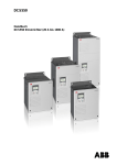
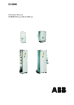
DCS800
Firmware manual
DCS800 Drives (20 to 5200 A)
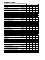
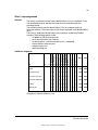
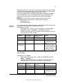
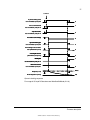
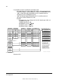
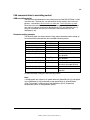
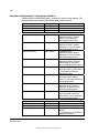
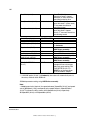
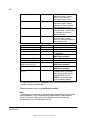
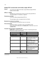
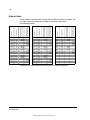
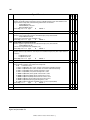
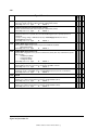
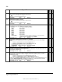
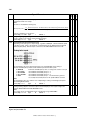
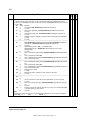
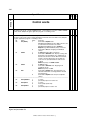
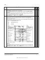
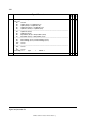
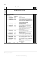
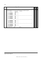
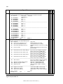
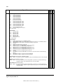
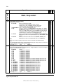
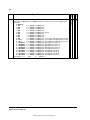
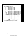
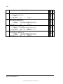
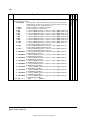
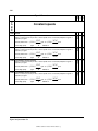
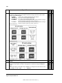
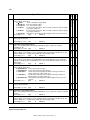
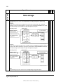
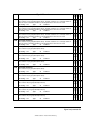
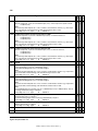
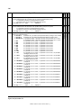
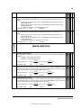
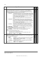
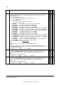
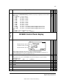
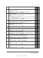
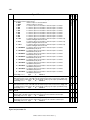
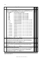
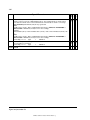
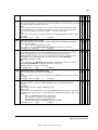
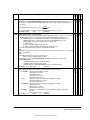
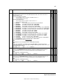
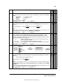
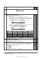
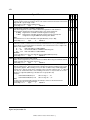
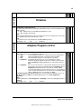
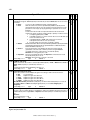
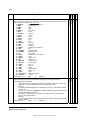
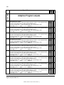
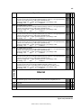
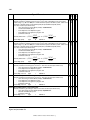
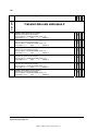
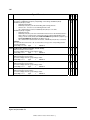
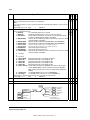
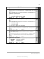
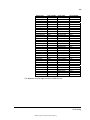
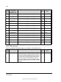
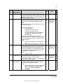
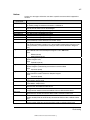
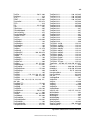
DCS800 Drive Manuals
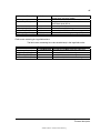
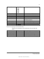
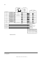
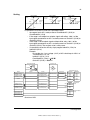
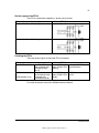
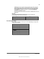
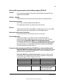
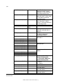
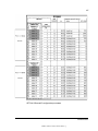
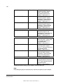
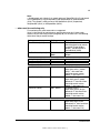
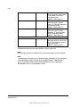
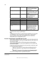
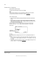
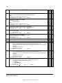
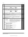
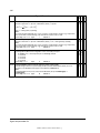
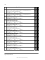
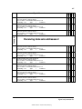
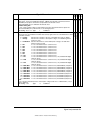
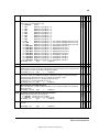
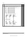
All the documents available for the drive system DCS800 are listed below:
Language
E
D
I
ES
F
DCS800 Quick Guide
DCS800 Tools & Documentation CD
DCS800 Converter module
Flyer DCS800
Technical Catalogue DCS800
Hardware Manual DCS800
Hardware Manual DCS800 update DCF503B/DCF504B
Firmware Manual DCS800
Installation according to EMC
Technical Guide
Service Manual DCS800
12-Pulse Manual
CMA-2 Board
Flyer Hard - Parallel
Public. number
3ADW000191
3ADW000211
x
x
x
x
x
x
3ADW000190
3ADW000192
3ADW000194
3ADW000194Z0301
3ADW000193
3ADW000032
3ADW000163
3ADW000195
3ADW000196
3ADW000136
3ADW000213
x
x
x
x
x
x
x
x
x
p
x
x
x
x
x
x
x
x
x
x
p
x
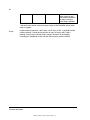
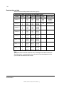
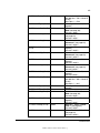
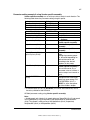
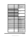
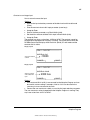
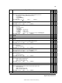
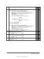
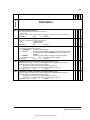
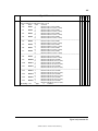
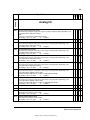
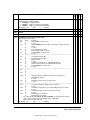
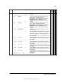
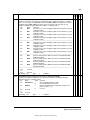
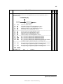
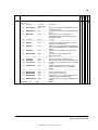
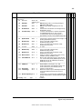
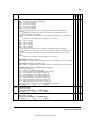
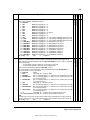
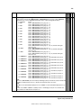
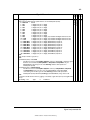
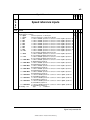
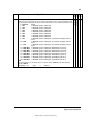
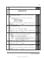
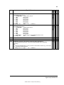
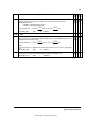
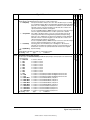
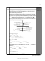
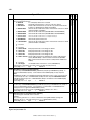
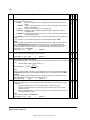
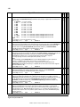
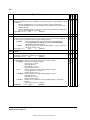
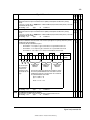
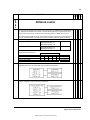
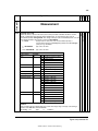
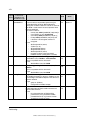
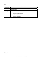
Drive Tools
DriveWindow 2.x - User's Manual
DriveOPC 2.x - User's Manual
Optical DDCS Communication Link
DDCS Branching Units - User’s Manual
3BFE64560981
3BFE00073846
3AFE63988235
3BFE64285513
x
x
x
x
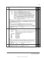
DCS800 Applications
PLC Programming with CoDeSys
61131 DCS800 target +tool description - Application Program
CoDeSys_V23
3ADW000199
x
x
DCS800 Crane Drive
DCS800 Crane Drive Manual suppl.
DCS800 Crane Drive Product note
3AST004143
PDC5 EN REVA
x
p
DCS800 Winder ITC
DCS800 Winder Product note
DCS800 Winder description ITC
Winder Questionnaire
PDC2 EN
3ADW000308
3ADW000253z
x
x
x
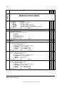
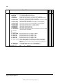
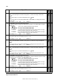
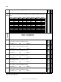
DCS800-E Panel Solution
Flyer DCS800-E Panel solution
Hardware Manual DCS800-E
3ADW000210
3ADW000224
x
x
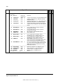
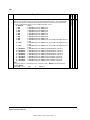
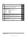
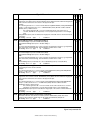
DCS800-A Enclosed Converters
Flyer DCS800-A
Technical Catalogue DCS800-A
Installation of DCS800-A
3ADW000213
3ADW000198
3ADW000091
x
x
x
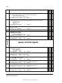
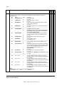
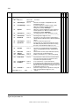
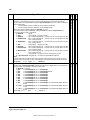
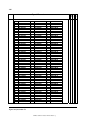
DCS800-R Rebuild System
Flyer DCS800-R
DCS800-R Manual
DCS500/DCS600 Size A5...A7, C2b, C3 and C4 Upgrade Kits
3ADW000007
3ADW000197
3ADW000256
x
x
x
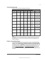
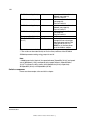
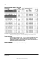
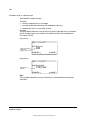
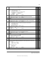
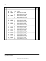
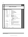
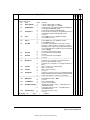
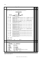
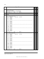
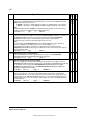
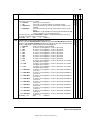
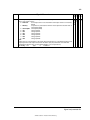
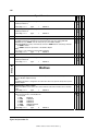
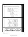
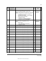
Extension Modules
RAIO-01 Analog IO Extension
RDIO-01 Digital IO Extension
RRIA-01 Resolver Interface Module
RTAC-01 Pulse Encoder Interface
RTAC-03 TTL Pulse Encoder Interface
AIMA R-slot extension
3AFE64484567
3AFE64485733
3AFE68570760
3AFE64486853
3AFE68650500
3AFE64661442
x
x
x
x
x
x
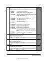
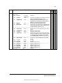
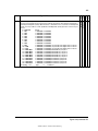
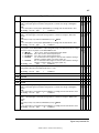
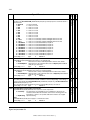
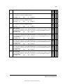
Serial Communication
Drive specific serial communication
NETA Remote diagnostic interface
3AFE64605062
x
3AFE64504215
x
3AFE64506005
3AFE64504223
3AFE64498851
3AFE64539736
x
x
x
x
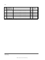
Fieldbus Adapter with DC Drives RPBA- (PROFIBUS)
Fieldbus Adapter with DC Drives RCAN-02 (CANopen)
Fieldbus Adapter with DC Drives RCNA-01 (ControlNet)
Fieldbus Adapter with DC Drives RDNA- (DeviceNet)
Fieldbus Adapter with DC Drives RMBA (MODBUS)
Fieldbus Adapter with DC Drives RETA (Ethernet)
x -> existing
Status 04.2010
p -> planned
DCS800 Drive Manuals-List_j.doc
CN
RU
PL
x
x
x
x
x
x
x
x
x
x
x
x
x
x
x
x
x
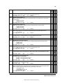
3
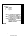
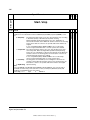
Safety instructions
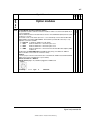
What this chapter contains
This chapter contains the safety instructions you must follow when installing,
operating and servicing the drive. If ignored, physical injury or death may follow, or
damage may occur to the drive, the motor or driven equipment. Read the safety
instructions before you work on the unit.
To which products this chapter applies
The information is valid for the whole range of the product DCS800, the converter
modules DCS800-S0x size D1 to D7, field exciter units DCF80x, etc. like the
Rebuild Kit DCS800-R00-9xxx.
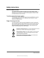
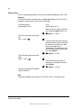
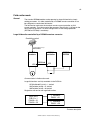
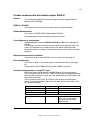
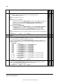
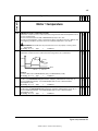
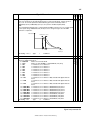
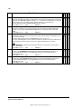
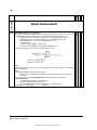
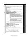
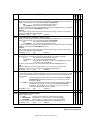
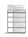
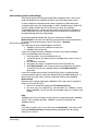
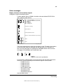
Usage of warnings and notes
There are two types of safety instructions throughout this manual: warnings and
notes. Warnings caution you about conditions which can result in serious injury or
death and/or damage to the equipment, and advise on how to avoid the danger.
Notes draw attention to a particular condition or fact, or give information on a
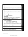
subject. The warning symbols are used as follows:
Dangerous voltage warning warns of high voltage which can cause
physical injury or death and/or damage to the equipment.
General danger warning warns about conditions, other than those
caused by electricity, which can result in physical injury or death
and/or damage to the equipment.
Electrostatic sensitive devices warning warns of electrostatic
discharge which can damage the equipment.
Safety instructions
3ADW000193R0701 DCS800 Firmware Manual e g
4
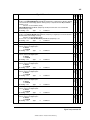
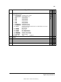
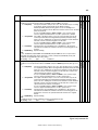
Installation and maintenance work
These warnings are intended for all who work on the drive, motor cable
or motor. Ignoring the instructions can cause physical injury or death
and/or damage to the equipment.
WARNING!
•
•
•
•
•
•
Only qualified electricians are allowed to install and maintain
the drive!
Never work on the drive, motor cable or motor when main power is
applied.
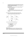
Always ensure by measuring with a multimeter (impedance at least
1 Mohm) that:
1. Voltage between drive input phases U1, V1 and W1 and
the frame is close to 0 V.
2. Voltage between terminals C+ and D- and the frame is
close to 0 V.
Do not work on the control cables when power is applied to the
drive or to the external control circuits. Externally supplied control
circuits may cause dangerous voltages inside the drive even when
the main power on the drive is switched off.
Do not make any insulation resistance or voltage withstand tests
on the drive or drive modules.
Isolate the motor cables from the drive when testing the insulation
resistance or voltage withstand of the cables or the motor.
When reconnecting the motor cable, always check that the C+ and
D- cables are connected with the proper terminal.
Note:
•
•
•
The motor cable terminals on the drive are at a dangerously high
voltage when the main power is on, regardless of whether the
motor is running or not.
Depending on the external wiring, dangerous voltages (115 V,
220 V or 230 V) may be present on the relay outputs of the drive
system (e.g. SDCS-IOB-2 and RDIO).
DCS800 with enclosure extension: Before working on the drive,
isolate the whole drive system from the supply.
Safety instructions
3ADW000193R0701 DCS800 Firmware Manual e g
5
Grounding
These instructions are intended for all who are responsible for the
grounding of the drive. Incorrect grounding can cause physical injury,
death and/or equipment malfunction and increase electromagnetic
interference.
WARNING!
•
•
•
•
•
Ground the drive, motor and adjoining equipment to ensure
personnel safety in all circumstances, and to reduce
electromagnetic emission and pick-up.
Make sure that grounding conductors are adequately sized and
marked as required by safety regulations.
In a multiple-drive installation, connect each drive separately to
protective earth (PE ).
Minimize EMC emission and make a 360° high frequency
grounding (e.g. conductive sleeves) of screened cable entries at
the cabinet lead-through plate.
Do not install a drive equipped with an EMC filter to an
ungrounded power system or a high resistance-grounded (over 30
ohms) power system.
Note:
•
•
Power cable shields are suitable as equipment grounding
conductors only when adequately sized to meet safety regulations.
As the normal leakage current of the drive is higher than 3.5 mA
AC or 10 mA DC (stated by EN 50178, 5.2.11.1), a fixed protective
earth connection is required.
Safety instructions
3ADW000193R0701 DCS800 Firmware Manual e g
6
Printed circuit boards and fiber optic cables
These instructions are intended for all who handle the circuit boards
and fiber optic cables. Ignoring the following instructions can cause
damage to the equipment.
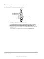
WARNING! The printed circuit boards contain components sensitive to
electrostatic discharge. Wear a grounding wrist band when handling
the boards. Do not touch the boards unnecessarily.
Use grounding strip:
ABB order no.: 3ADV050035P0001
WARNING! Handle the fiber optic cables with care. When unplugging
optic cables, always grab the connector, not the cable itself. Do not
touch the ends of the fibers with bare hands as the fiber is extremely
sensitive to dirt. The minimum allowed bend radius is 35 mm (1.38 in.).
Safety instructions
3ADW000193R0701 DCS800 Firmware Manual e g
7
Mechanical installation
These notes are intended for all who install the drive. Handle the unit
carefully to avoid damage and injury.
WARNING!
•
•
•
•
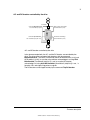
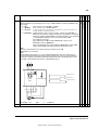
DCS800 sizes D4 ... D7: The drive is heavy. Do not lift it alone. Do
not lift the unit by the front cover. Place units D4 and D5 only on its
back.
DCS800 sizes D5 ... D7: The drive is heavy. Lift the drive by the
lifting lugs only. Do not tilt the unit. The unit will overturn from a tilt
of about 6 degrees.
Make sure that dust from drilling does not enter the drive when
installing. Electrically conductive dust inside the unit may cause
damage or lead to malfunction.
Ensure sufficient cooling.
Do not fasten the drive by riveting or welding.
Safety instructions
3ADW000193R0701 DCS800 Firmware Manual e g
8
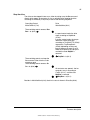
Operation
These warnings are intended for all who plan the operation of the drive
or operate the drive. Ignoring the instructions can cause physical injury
or death and/or damage to the equipment.
WARNING!
•
•
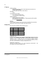
Before adjusting the drive and putting it into service, make sure
that the motor and all driven equipment are suitable for operation
throughout the speed range provided by the drive. The drive can
be adjusted to operate the motor at speeds above and below the
base speed.
Do not control the motor with the disconnecting device
(disconnecting mains); instead, use the control panel keys
•
•
•
and
, or commands via the I/O board of the drive.
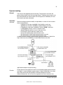
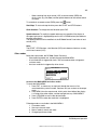
Mains connection
You can use a disconnect switch (with fuses) to disconnect the
electrical components of the drive from the mains for installation
and maintenance work. The type of disconnect switch used must
be as per EN 60947-3, Class B, so as to comply with EU
regulations, or a circuit-breaker type which switches off the load
circuit by means of an auxiliary contact causing the breaker's main
contacts to open. The mains disconnect must be locked in its
"OPEN" position during any installation and maintenance work.
EMERGENCY STOP buttons must be installed at each control
desk and at all other control panels requiring an emergency stop
function. Pressing the STOP button on the control panel of the
drive will neither cause an emergency stop of the motor, nor will
the drive be disconnected from any dangerous potential.
To avoid unintentional operating states, or to shut the unit down in
case of any imminent danger according to the standards in the
safety instructions it is not sufficient to merely shut down the drive
via signals "RUN", "drive OFF" or "Emergency Stop" respectively
"control panel" or "PC tool".
Intended use
The operating instructions cannot take into consideration every
possible case of configuration, operation or maintenance. Thus,
they mainly give such advice only, which is required by qualified
personnel for normal operation of the machines and devices in
industrial installations.
If in special cases the electrical machines and devices are intended for use in non-industrial installations - which may require
stricter safety regulations (e.g. protection against contact by
children or similar) - these additional safety measures for the
installation must be provided by the customer during assembly.
Safety instructions
3ADW000193R0701 DCS800 Firmware Manual e g
9
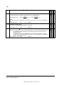
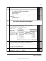
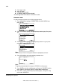
Note:
•
When the control location is not set to Local (L not shown in the
status row of the display), the stop key on the control panel will not
stop the drive. To stop the drive using the control panel, press the
LOC/REM key and then the stop key
.
Safety instructions
3ADW000193R0701 DCS800 Firmware Manual e g
10
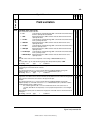
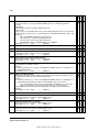
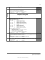
Table of contents
Safety instructions
3
What this chapter contains......................................................................................................... 3
To which products this chapter applies ...................................................................................... 3
Usage of warnings and notes..................................................................................................... 3
Installation and maintenance work............................................................................................. 4
Grounding....................................................................................................................... 5
Mechanical installation ............................................................................................................... 7
Operation ................................................................................................................................... 8
Table of contents
10
Introduction
23
Chapter overview.......................................................................................................... 23
Before You Start ........................................................................................................... 23
What this manual contains ........................................................................................... 23
Start-up
24
Chapter overview.......................................................................................................... 24
General......................................................................................................................... 24
Start-up procedure ................................................................................................................... 25
Tools............................................................................................................................. 25
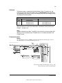
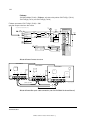
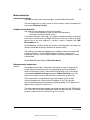
Checking with the power switched off .......................................................................... 25
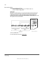
Checking with the power switched on .......................................................................... 27
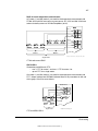
Commissioning a DCS800 ....................................................................................................... 28
Connect DCS800 to PC with DriveWindow Light ..................................................................... 28
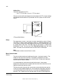
Commissioning a DCS800 with the wizard .............................................................................. 29
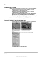
Commissioning a DCS800 with DriveWindow.......................................................................... 30
Requirements ............................................................................................................... 30
01, 02 Macro assistant / Name plate data .................................................................... 30
03 Autotuning field current controller ............................................................................ 31
04 Autotuning armature current controller .................................................................... 31
05 Speed feedback assistant ....................................................................................... 32
Analog tacho fine tune procedure ................................................................ 32
06 Autotuning speed controller..................................................................................... 32
07 Field weakening assistant ....................................................................................... 33
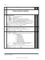
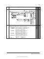
Manual tuning........................................................................................................................... 34
I/O configuration ........................................................................................................... 34
Field current controller.................................................................................................. 34
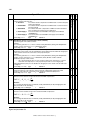
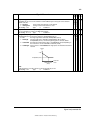
Armature current controller ........................................................................................... 35
Control principle ........................................................................................... 35
Manual tuning............................................................................................... 36
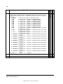
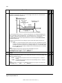
Analog tacho................................................................................................................. 41
Manual tuning............................................................................................... 42
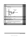
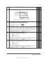
Speed controller ........................................................................................................... 42
Basics........................................................................................................... 42
Manual tuning............................................................................................... 43
EMF controller .............................................................................................................. 45
Table of contents
3ADW000193R0701 DCS800 Firmware Manual e g
11
Basics............................................................................................................45
Manual tuning................................................................................................45
Flux linearization............................................................................................................47
Basics............................................................................................................47
Manual tuning................................................................................................48
Thyristor diagnosis ........................................................................................................50
Basics............................................................................................................50
Check all thyristors ........................................................................................50
Check individual firing pulses ........................................................................50
Firmware description
52
Chapter overview...........................................................................................................52
Identification of the firmware versions ...........................................................................52
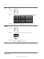
Start / stop sequences ..............................................................................................................53
General..........................................................................................................................53
Switch on sequence ......................................................................................................53
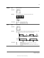
Start the drive ................................................................................................................54
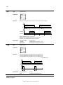
Stop the drive ................................................................................................................55
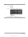
Field excitation ..........................................................................................................................58
General..........................................................................................................................58
Field Reversal................................................................................................................58
Field control...................................................................................................58
Field reference hysteresis .............................................................................59
Force field current direction...........................................................................59
Reversal time ................................................................................................59
Bumpless transition .......................................................................................59
Optitorque......................................................................................................................59
Field current reference gain ..........................................................................59
Field current monitoring.................................................................................................60
Field minimum trip .........................................................................................60
Flux reversal..................................................................................................60
Field reversal hysteresis................................................................................60
Field reversal active ......................................................................................60
Field Heating .................................................................................................................60
Overview .......................................................................................................60
Modes of operation........................................................................................61
E-stop ............................................................................................................62
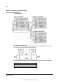
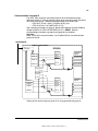
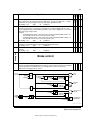
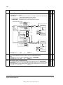
Field exciter mode.....................................................................................................................63
General..........................................................................................................................63
Large field exciter controlled by a DCS800 armature converter....................................63
Parameters to be set in the DCS800 armature converter: ............................64
Parameters to be set in large field exciters: ..................................................64
Field current autotuning for large field exciters: ............................................65
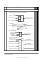
Stand alone field exciter ................................................................................................66
Parameters to be set in the stand alone field exciter: ...................................66
Field current autotuning for stand alone field exciter:....................................67
DC-breaker, DC-contactor ........................................................................................................68
General..........................................................................................................................68
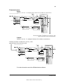
HVCB controlled externally, DC-breaker controlled by the drive...................................68
DC-contactor US version ..........................................................................................................69
Table of contents
3ADW000193R0701 DCS800 Firmware Manual e g
12
AC- and DC-breaker controlled by the drive................................................................. 71
No AC-breaker, DC-breaker controlled by the drive ..................................................... 72
AC-breaker controlled by the drive, DC-breaker controlled externally.......................... 73
No AC-breaker, DC-breaker controlled externally ........................................................ 74
Command Trip DC-breaker .......................................................................................... 74
Dynamic braking ...................................................................................................................... 75
General......................................................................................................................... 75
Operation...................................................................................................................... 75
Activation...................................................................................................... 75
Function........................................................................................................ 75
Deactivation.................................................................................................. 76
Position counter ....................................................................................................................... 78
General......................................................................................................................... 78
Counting procedure ...................................................................................................... 78
Synchronization ............................................................................................................ 78
I/O configuration
81
Chapter overview.......................................................................................................... 81
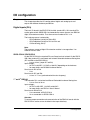
Digital inputs (DI’s) ................................................................................................................... 81
SDCS-CON-4 / SDCS-IOB-2........................................................................................ 81
st
nd
1 and 2 RDIO-01 ....................................................................................................... 81
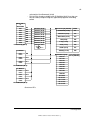
Configuration ................................................................................................................ 82
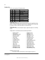
Digital outputs (DO’s) ............................................................................................................... 84
SDCS-CON-4 / SDCS-IOB-2........................................................................................ 84
st
nd
1 and 2 RDIO-01 ....................................................................................................... 84
Configuration ................................................................................................................ 85
Analog inputs (AI’s) .................................................................................................................. 87
SDCS-CON-4 ............................................................................................................... 87
SDCS-IOB-3 ................................................................................................................. 87
st
1 RAIO-01 ................................................................................................................... 88
nd
2 RAIO-01................................................................................................................... 88
Configuration ................................................................................................................ 89
Scaling.......................................................................................................................... 89
Analog outputs (AO’s) .............................................................................................................. 91
SDCS-CON-4 / SDCS-IOB-3........................................................................................ 91
st
1 RAIO-01 ................................................................................................................... 91
nd
2 RAIO-01................................................................................................................... 92
Configuration ................................................................................................................ 92
Scaling.......................................................................................................................... 93
Communication
94
Chapter overview.......................................................................................................... 94
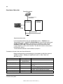
DCSLink with SDCS-DSL-4 ..................................................................................................... 94
General......................................................................................................................... 94
Excitation, commissioning a FEX-4.......................................................................................... 94
Layout FEX-4................................................................................................................ 94
Layout SDCS-DSL-4 .................................................................................................... 94
Set the FEX-4 type ....................................................................................................... 95
Set the node numbers, transmission speed and the communication supervision ........ 95
Set the DCSLink ........................................................................................................... 96
Table of contents
3ADW000193R0701 DCS800 Firmware Manual e g
13
Set the supply of the FEX-4...........................................................................................97
Checking the FEX-4 ......................................................................................................97
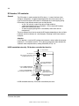
Master-follower, commissioning................................................................................................98
Set the DCSLink hardware ............................................................................................98
Set the node ID numbers and transmission speed........................................................99
Activate the mailboxes...................................................................................................99
Activate the communication supervision .......................................................................99
Send and receive values .............................................................................................100
Firmware structure.......................................................................................................101
Additional settings .......................................................................................................102
Drive-to-drive communication .................................................................................................103
Set the DCSLink hardware ..........................................................................................103
Set the node ID numbers and transmission speed......................................................104
Activate the mailboxes.................................................................................................104
Activate the communication supervision .....................................................................104
Send and receive values .............................................................................................105
12-pulse ..................................................................................................................................106
Set the DCSLink hardware ..........................................................................................106
Set the node numbers, transmission speed and the communication supervision.......107
DDCS channels with SDCS-COM-8 .......................................................................................108
General........................................................................................................................108
Integer scaling on the DDCS link.................................................................................108
Ch0 communication to overriding control................................................................................109
ABB overriding control.................................................................................................109
Parameter setting example..........................................................................................109
Received data set table ...............................................................................................110
Transmitted data set table ...........................................................................................111
Fieldbus communication (N-type)................................................................................111
Ch1 I/O devices ......................................................................................................................112
Ch2 Master-follower link..........................................................................................................112
General........................................................................................................................112
Link configuration ........................................................................................................112
Master..........................................................................................................................112
Followers .....................................................................................................................113
Firmware structure.......................................................................................................113
Toggle between speed- and torque control .................................................................115
Follower diagnostics ....................................................................................................115
Master-follower link specification.................................................................................115
Ch3 commissioning and maintenance tools............................................................................116
DriveWindow ...............................................................................................................116
Ethernet communication for monitoring with Ethernet adapter NETA-01 ...............................117
General........................................................................................................................117
NETA-01 - DCS800 .....................................................................................................117
Related documentation................................................................................................117
NETA-01 configuration ................................................................................................117
Mechanical and electrical installation ..........................................................................118
Drive configuration.......................................................................................................118
CANopen communication with fieldbus adapter RCAN-01 .....................................................119
General........................................................................................................................119
RCAN-01 - DCS800 ....................................................................................................119
Table of contents
3ADW000193R0701 DCS800 Firmware Manual e g
14
Related documentation............................................................................................... 119
Overriding control configuration.................................................................................. 119
EDS file....................................................................................................................... 119
Mechanical and electrical installation ......................................................................... 119
Drive configuration...................................................................................................... 119
Parameter setting example 1 using group 51 ............................................................. 119
Further information ..................................................................................................... 121
Parameter setting example 2 using groups 90 and 92 ............................................... 122
Switch on sequence ................................................................................................... 124
ControlNet communication with fieldbus adapter RCNA-01................................................... 125
General....................................................................................................................... 125
RCNA-01 - DCS800 ................................................................................................... 125
Related documentation............................................................................................... 125
Overriding control configuration.................................................................................. 125
EDS file....................................................................................................................... 125
Mechanical and electrical installation ......................................................................... 125
Drive configuration...................................................................................................... 125
Parameter setting example 1 using ABB Drives assembly......................................... 125
Parameter setting example 2 using Vendor specific assembly .................................. 127
Setting of parameter groups 51, 90 and 92 ................................................................ 128
Further information ..................................................................................................... 128
Switch on sequence ................................................................................................... 128
DeviceNet communication with fieldbus adapter RDNA-01 ................................................... 129
General....................................................................................................................... 129
RDNA-01 - DCS800 ................................................................................................... 129
Related documentation............................................................................................... 129
Overriding control configuration.................................................................................. 129
EDS file....................................................................................................................... 129
Mechanical and electrical installation ......................................................................... 129
Drive configuration...................................................................................................... 129
Parameter setting example 1 using ABB Drives assembly......................................... 129
Parameter setting example 2 using User specific assembly ...................................... 131
Setting of parameter groups 51, 90 and 92 ................................................................ 132
Further information ..................................................................................................... 132
Switch on sequence ................................................................................................... 132
Ethernet/IP communication with fieldbus adapter RETA-01 .................................................. 133
General....................................................................................................................... 133
RETA-01 - DCS800 .................................................................................................... 133
Related documentation............................................................................................... 133
EDS file....................................................................................................................... 133
Mechanical and electrical installation ......................................................................... 133
Drive configuration...................................................................................................... 133
Parameter setting example using Ethernet/IP ABB Drives communication profile..... 133
Up to 4 data words ..................................................................................................... 135
Up to 12 data words ................................................................................................... 135
Switch on sequence ................................................................................................... 138
Modbus (RTU) communication with fieldbus adapter RMBA-01 ............................................ 139
General....................................................................................................................... 139
RMBA-01 - DCS800 ................................................................................................... 139
Related documentation............................................................................................... 139
Table of contents
3ADW000193R0701 DCS800 Firmware Manual e g
15
Mechanical and electrical installation ..........................................................................139
Drive configuration.......................................................................................................139
Parameter setting example … .....................................................................................139
… when controlling a drive ..........................................................................................139
… when used for monitoring only ................................................................................141
Setting of PLC, parameter groups 90 and 92 ..............................................................143
Switch on sequence ....................................................................................................143
Modbus/TCP communication with fieldbus adapter RETA-01 ................................................144
General........................................................................................................................144
RETA-01 - DCS800 .....................................................................................................144
Related documentation................................................................................................144
Mechanical and electrical installation ..........................................................................144
Drive configuration.......................................................................................................144
Parameter setting example using Modbus/TCP ..........................................................144
Switch on sequence ....................................................................................................146
Profibus communication with fieldbus adapter RPBA-01........................................................147
General........................................................................................................................147
RPBA-01 - DCS800.....................................................................................................147
Related documentation................................................................................................147
Overriding control configuration...................................................................................147
Mechanical and electrical installation ..........................................................................147
Drive configuration.......................................................................................................147
Parameter setting example 1 using PPO Type 1 ........................................................147
Parameter setting example 2 using PPO types 2, 4 and 5..........................................148
Communication via group 51.......................................................................................149
Communication via group 90 and group 92.................................................................150
Switch on sequence ....................................................................................................151
Data set table ..........................................................................................................................152
Adaptive Program (AP)
153
Chapter overview.........................................................................................................153
What is the Adaptive Program.....................................................................................153
Features ......................................................................................................................153
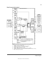
How to build the program ............................................................................................154
How to connect the Application Program with the firmware ........................................154
Block Parameter Set for block 1 ..................................................................................155
How to control the execution of the program...............................................................156
DWL AP ..................................................................................................................................157
General........................................................................................................................157
Important keys and buttons .........................................................................................157
Program modes ...........................................................................................................157
Change to Edit mode...................................................................................................157
Insert function blocks...................................................................................................158
Connect function blocks ..............................................................................................159
Set the Time level........................................................................................................161
Saving AP applications................................................................................................161
Function blocks .......................................................................................................................162
General rules ...............................................................................................................162
Block inputs .................................................................................................................162
Block input attributes ...................................................................................163
Table of contents
3ADW000193R0701 DCS800 Firmware Manual e g
16
Parameter value as an integer input .......................................................... 164
How the block handles the input ................................................................ 164
How to select the input ............................................................................... 164
Constant as an integer input ...................................................................... 165
How to set and connect the input ............................................................... 165
Parameter value as a boolean input........................................................... 166
How the block handles the input ................................................................ 166
Constant as a boolean input....................................................................... 167
How to set and connect the input ............................................................... 167
String input ................................................................................................. 167
How to select the input ............................................................................... 167
Function blocks ...................................................................................................................... 168
ABS ............................................................................................................................ 168
ADD ............................................................................................................................ 169
AND ............................................................................................................................ 169
Bitwise ........................................................................................................................ 170
Bset ............................................................................................................................ 171
Compare..................................................................................................................... 171
Count .......................................................................................................................... 172
D-Pot .......................................................................................................................... 172
Event .......................................................................................................................... 173
Filter............................................................................................................................ 173
Limit ............................................................................................................................ 174
MaskSet...................................................................................................................... 174
Max............................................................................................................................. 175
Min.............................................................................................................................. 175
MulDiv......................................................................................................................... 175
NotUsed...................................................................................................................... 176
OR .............................................................................................................................. 176
ParRead ..................................................................................................................... 176
ParWrite...................................................................................................................... 177
PI ................................................................................................................................ 177
PI-Bal.......................................................................................................................... 178
Ramp .......................................................................................................................... 178
Sqrt ............................................................................................................................. 179
SqWav ........................................................................................................................ 179
SR............................................................................................................................... 180
Switch-B ..................................................................................................................... 180
Switch-I....................................................................................................................... 181
TOFF .......................................................................................................................... 181
TON ............................................................................................................................ 182
Trigg ........................................................................................................................... 182
XOR............................................................................................................................ 183
Diagram.................................................................................................................................. 184
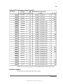
Signal and parameter list
185
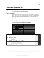
Signals and parameters ......................................................................................................... 185
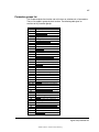
Signal groups list.................................................................................................................... 185
Parameter groups list ............................................................................................................. 187
Signal and parameter list ....................................................................................................... 190
Table of contents
3ADW000193R0701 DCS800 Firmware Manual e g
17
Group 1........................................................................................................................190
Physical actual values .................................................................................190
Group 2........................................................................................................................194
Speed controller signals ..............................................................................194
Group 3........................................................................................................................198
Reference actual values..............................................................................198
Group 4........................................................................................................................201
Information ..................................................................................................201
Group 5........................................................................................................................209
Analog I/O ...................................................................................................209
Group 6........................................................................................................................210
Drive logic signals .......................................................................................210
Group 7........................................................................................................................216
Control words ..............................................................................................216
Group 8........................................................................................................................222
Status / limit words ......................................................................................222
Group 9........................................................................................................................228
Fault / alarm words......................................................................................228
Group 10......................................................................................................................244
Start / stop select ........................................................................................244
Group 11......................................................................................................................257
Speed reference inputs ...............................................................................257
Group 12......................................................................................................................264
Constant speeds .........................................................................................264
Group 13......................................................................................................................265
Analog inputs ..............................................................................................265
Group 14......................................................................................................................269
Digital outputs .............................................................................................269
Group 15......................................................................................................................271
Analog outputs ............................................................................................271
Group 16......................................................................................................................273
System control inputs ..................................................................................273
Group 19......................................................................................................................276
Data storage................................................................................................276
Group 20......................................................................................................................278
Limits ...........................................................................................................278
Group 21......................................................................................................................282
Start / stop ...................................................................................................282
Group 22......................................................................................................................286
Speed ramp.................................................................................................286
Group 23......................................................................................................................289
Speed reference..........................................................................................289
Group 24......................................................................................................................294
Speed control ..............................................................................................294
Group 25......................................................................................................................299
Torque reference.........................................................................................299
Group 26......................................................................................................................300
Torque reference handling ..........................................................................300
Group 30......................................................................................................................304
Fault functions .............................................................................................304
Table of contents
3ADW000193R0701 DCS800 Firmware Manual e g
18
Group 31..................................................................................................................... 315
Motor 1 temperature................................................................................... 315
Group 34..................................................................................................................... 317
DCS800 Control Panel display................................................................... 317
Group 40..................................................................................................................... 318
PID control.................................................................................................. 318
Group 42..................................................................................................................... 321
Brake control .............................................................................................. 321
Group 43..................................................................................................................... 327
Current control............................................................................................ 327
Group 44..................................................................................................................... 333
Field excitation ........................................................................................... 333
Group 45..................................................................................................................... 340
Field converter settings .............................................................................. 340
Group 47..................................................................................................................... 347
12-pulse operation...................................................................................... 347
Group 49..................................................................................................................... 348
Shared motion ............................................................................................ 348
Group 50..................................................................................................................... 360
Speed measurement .................................................................................. 360
Group 51..................................................................................................................... 367
Fieldbus...................................................................................................... 367
Group 52..................................................................................................................... 368
Modbus....................................................................................................... 368
Group 60, …, 69 ......................................................................................................... 369
Application program parameters ................................................................ 369
Group 70..................................................................................................................... 370
DDCS control ............................................................................................. 370
Group 71..................................................................................................................... 375
Drivebus ..................................................................................................... 375
Group 83..................................................................................................................... 375
Adaptive Program control........................................................................... 375
Group 84..................................................................................................................... 377
Adaptive Program....................................................................................... 377
Group 85..................................................................................................................... 380
User constants ........................................................................................... 380
Group 86..................................................................................................................... 382
Adaptive Program outputs.......................................................................... 382
Group 88..................................................................................................................... 383
Internal ....................................................................................................... 383
Group 90..................................................................................................................... 385
Receiving data sets addresses 1 ............................................................... 385
Group 91..................................................................................................................... 387
Receiving data sets addresses 2 ............................................................... 387
Group 92..................................................................................................................... 388
Transmit data sets addresses 1 ................................................................. 388
Group 93..................................................................................................................... 390
Transmit data sets addresses 2 ................................................................. 390
Group 94..................................................................................................................... 391
DCSLink control ......................................................................................... 391
Table of contents
3ADW000193R0701 DCS800 Firmware Manual e g
19
Group 97......................................................................................................................399
Measurement ..............................................................................................399
Group 98......................................................................................................................407
Option modules ...........................................................................................407
Group 99......................................................................................................................415
Start-up data ...............................................................................................415
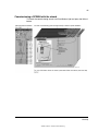
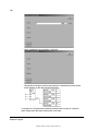
DCS800 Control Panel operation
420
Chapter overview.........................................................................................................420
Start-up........................................................................................................................420
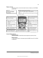
DCS800 Control Panel ................................................................................................420
Display overview..........................................................................................................421
General display features..............................................................................................421
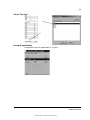
Output mode................................................................................................................422
Other modes................................................................................................................423
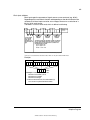
Maintenance ................................................................................................................428
Fault tracing
429
Chapter overview.........................................................................................................429
General........................................................................................................................429
Fault modes ................................................................................................429
Converter protection ...............................................................................................................429
Auxiliary undervoltage .................................................................................................429
Armature overcurrent...................................................................................................429
Converter overtemperature .........................................................................................429
Auto-reclosing (mains undervoltage)...........................................................................430
Mains synchronism......................................................................................................431
Mains overvoltage .......................................................................................................431
Communication loss ....................................................................................................431
Fan, field and mains contactor acknowledge ..............................................................432
External fault................................................................................................................432
Bridge reversal ............................................................................................................433
Analog input monitor....................................................................................................433
Motor protection ......................................................................................................................435
Armature overvoltage ..................................................................................................435
Residual current detection...........................................................................................435
Measured motor temperature ......................................................................................435
Klixon...........................................................................................................................438
Motor thermal model....................................................................................................438
Field overcurrent..........................................................................................................441
Armature current ripple................................................................................................441
Speed feedback monitor..............................................................................................442
Stall protection.............................................................................................................443
Overspeed protection ..................................................................................................443
Current rise..................................................................................................................444
Field undercurrent .......................................................................................................444
Tacho / pulse encoder polarity ....................................................................................444
Tacho range ................................................................................................................444
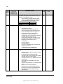
Status messages ....................................................................................................................445
Display of status, fault and alarm signals ....................................................................445
Table of contents
3ADW000193R0701 DCS800 Firmware Manual e g
20
Categories of signals and display options .................................................. 445
General messages ..................................................................................................... 446
Power-up errors (E) .................................................................................................... 446
Fault signals (F).......................................................................................................... 447
SDCS-COM-8 messages ........................................................................... 464
Alarm signals (A) ........................................................................................................ 465
Disappearing system alarm ........................................................................................ 475
User defined alarm by Adaptive Program................................................................... 475
Notices........................................................................................................................ 477
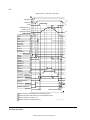
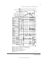
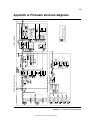
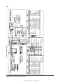
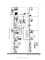
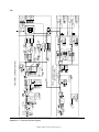
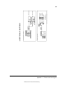
Appendix A: Firmware structure diagrams
479
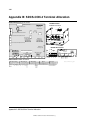
Appendix B: SDCS-CON-4 Terminal Allocation
484
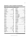
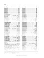
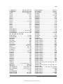
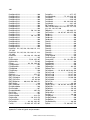
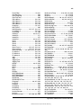
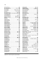
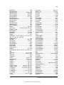
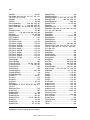
Appendix C: Index of signals and parameters
485
Table of contents
3ADW000193R0701 DCS800 Firmware Manual e g
21
Chapters not yet available
3ADW000193R0701 DCS800 Firmware Manual e g
22
3ADW000193R0701 DCS800 Firmware Manual e g
23
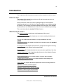
Introduction
Chapter overview
This chapter describes the purpose, contents and the intended use of this manual.
Before You Start
The purpose of this manual is to provide you with the information necessary to
control and program the drive.
Study carefully the Safety instructions at the beginning of this manual before
attempting any work on or with the drive. Read through this manual before startingup the drive. The installation and commissioning instructions given in the DCS800
Hardware Manual and DCS800 Quick Guide must also be read before proceeding.
This manual describes the standard DCS800 firmware.
What this manual contains
The Safety instructions can be found at the beginning of this manual.
Introduction to this manual, the chapter you are currently reading, introduces you
to this manual.
Start-up, this chapter describes the basic start-up procedure of the drive.
Firmware description, this chapter describes how to control the drive with standard
firmware.
I/O configuration, this chapter describes the I/O configuration of digital and analog
inputs and outputs with different hardware possibilities.
Communication, this chapter describes the communication capabilities of the drive.
Adaptive Program (AP), this chapter describes the basics of the Adaptive Program
and instructs how to build a program.
Signal and parameter list, this chapter contains all signals and parameters.
DCS800 Control Panel operation, this chapter describes the handling of the
DCS800 Control Panel.
Fault Tracing, this chapter describes the protections and fault tracing of the drive.
Appendix A: Firmware structure diagram
Appendix B: SDCS-CON-4 Terminal Allocation
Appendix C: Index of signal and parameters
Introduction to this manual
3ADW000193R0701 DCS800 Firmware Manual e g
24
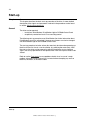
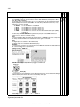
Start-up
Chapter overview
This chapter describes the basic start-up procedure of the drive. A more detailed
description of the signals and parameters involved in the procedure can be found
in section Signal and parameter list.
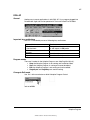
General
The drive can be operated:
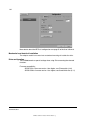
locally from DriveWindow, DriveWindow Light or DCS800 Control Panel
respectively remote from local I/O or overriding control.
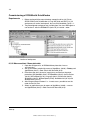
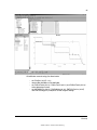
The following start-up procedure uses DriveWindow (for further information about
DriveWindow, consult its online help). However, parameters can also be changed
with DriveWindow Light or the DCS800 Control Panel.
The start-up procedure includes actions that need only be taken when powering up
the drive for the first time in a new installation (e.g. entering the motor data). After
the start-up, the drive can be powered up without using these start-up functions
again. The start-up procedure can be repeated later if the start-up data needs to be
altered.
Refer to section Fault tracing in case problems should arise. In case of a major
problem, disconnect mains and wait for 5 minutes before attempting any work on
the drive, the motor, or the motor cables.
Start-up
3ADW000193R0701 DCS800 Firmware Manual e g
25
Start-up procedure
The Safety Instructions at the beginning of this manual have to be observed with
extreme care during the start-up procedure!
The start-up procedure should only be carried out by a qualified electrician.
Check the mechanical and electrical installation the drive according to the DCS800
Hardware Manual.
Tools
For drive commissioning following software tools are mandatory:
DriveWindow Light including commissioning wizard and DWL AP for
Adaptive Program and
DriveWindow for fast drive monitoring using SDCS-COM-8.
For drive commissioning following tools are mandatory in addition to standard tools:
An oscilloscope including memory function with either galvanically isolating
transformer or isolating amplifier for safe measurements.
A clamp on current probe. In case the scaling of the DC load current needs
to be checked it must be a DC clamp on current probe.
A voltmeter.
Make sure that all equipment in use is suitable for the voltage level applied to the
power part!
Checking with the power switched off
Check the settings of:
the main breaker (e.g. overcurrent = 1.6 * In, short circuit current = 10 * In,
time for thermal tripping = 10 s),
time, overcurrent, thermal and voltage relays,
the earth fault protection (e.g. Bender relay)
Check the insulation of the mains voltage cables or busbars between the
secondary side of the dedicated transformer and the drive:
disconnect the dedicated transformer from its incoming voltage,
check that all circuits between the mains and the drive (e.g. control /
auxiliary voltage) are disconnected,
measure the insulation resistance between L1 - L2, L1 - L3, L2 - L3, L1 PE, L2 - PE, L3 - PE,
the result should be M:s
Check the installation:
crosscheck the wiring with the drawings,
check the mechanical mounting of the motor and pulse encoder or analog
tacho,
make sure that the motor is connected in a correct way (armature, field,
serial windings, cable shields),
check the connections of the motor fan if existing,
make sure that the converter fan is connected correctly especially in
modules size D6 and D7 were star or delta connection is possible,
Start-up
3ADW000193R0701 DCS800 Firmware Manual e g
26
if a pulse encoder is used make sure that pulse encoder's auxiliary voltage
connection corresponds to its voltage and that the channel connection
corresponds to correct direction of rotation,
check that the shielding of the pulse encoder's cable is connected to the TE
bar of the DCS800,
if an analog tacho is used make sure that it is connected to the proper
voltage input at the SDCS-CON-4:
X3:1 - X3:4 (90 - 270 V)
X3:2 - X3:4 (30 - 90 V)
X3:3 - X3:4 (8 - 30 V)
for all other cables make sure that both ends of the cables are connected
and they do not cause any damage or danger when power is being
switched on
Measuring the insulation resistance of the motor cables and the motor:
isolate the motor cables from the drive before testing the insulation
resistance or voltage withstand of the cables or the motor,
Instructions how to measure the insulation resistance
measure the insulation resistance between:
1. + cables and PE,
2. - cables and PE,
3. armature cables and field cables,
4. field - cable and PE,
5. field + cable and PE,
the result should be M:s
Setting of Jumpers:
The boards of the DCS800 include jumpers to adapt the boards to different
applications. The position of the jumpers must be checked before connecting
voltage. For specific jumper settings consult the DCS800 Hardware Manual.
Start-up
3ADW000193R0701 DCS800 Firmware Manual e g
27
Drive data
Check following items for each drive and mark the differences in the delivery
documents:
motor, analog tacho or pulse encoder and cooling fan rating plates data,
direction of motor rotation,
maximum and minimum speed and if fixed speeds are used,
speed scaling factors:
e.g. gear ratio, roll diameter,
acceleration and deceleration times,
operating modes:
e.g. stop mode, E-stop mode,
the amount of motors connected
Checking with the power switched on
There is dangerous voltage inside the cabinet!
Switching the power on:
prior to connecting the voltage proceed as follows:
1. ensure that all the cable connections are checked and that the
connections can't cause any danger,
2. close all doors of enclosed converter before switching power on,
3. be ready to trip the supply transformer if anything abnormal occurs,
4. switch the power on
Measurements made with power on:
check the operation of the auxiliary equipment,
check the circuits for external interfaces on site:
1. E-stop circuit,
2. remote control of the main breaker,
3. signals connected to the control system,
4. other signals which remain to be checked
Connecting voltage to the drive:
check from the delivery diagrams the type of boards and converters which
are used in the system,
check all time relay and breaker settings,
close the supply disconnecting device (check the connection from the
delivery diagrams),
close all protection switches one at a time and measure for proper voltage
Start-up
3ADW000193R0701 DCS800 Firmware Manual e g
28
Commissioning a DCS800
Nominal values of the converter can be found in group 4, check following signals:
ConvNomVolt (4.04), nominal AC converter voltage in V read from
TypeCode (97.01) or S ConvScaleVolt (97.03),
ConvNomCur (4.05), nominal converter DC current in A read from
TypeCode (97.01) or S ConvScaleCur (97.02),
ConvType (4.14), recognized converter type read from TypeCode (97.01),
QuadrantType (4.15), recognized converter quadrant type read from
TypeCode (97.01) or S BlockBrdg2 (97.07),
MaxBridgeTemp (4.17), maximum bridge temperature in degree centigrade
read from TypeCode (97.01) or S MaxBrdgTemp (97.04)
If signals are not correct adapt them, see group 97 in this manual.
Connect DCS800 to PC with DriveWindow Light
Connect a normal serial cable from the PC COM port to X34 on the drive:
Start DriveWindow Light and check the communication settings:
Example with COM1.
Start-up
3ADW000193R0701 DCS800 Firmware Manual e g
29
Commissioning a DCS800 with the wizard
To launch the commissioning wizard start DriveWindow Light and press the Wizard
button:
Start-up
3ADW000193R0701 DCS800 Firmware Manual e g
30
Commissioning a DCS800 with DriveWindow
Requirements
1. Before starting with the commissioning, connect the drive (via Ch3 on
SDCS-COM-8) with DriveWindow (via e.g. NDPA-02 and NDPC-12). All
workspaces are ‘online’ workspaces, thus use Ch3 NodeAddr (70.22) = 1.
2. The preconfigured workspaces are available from Your local ABB agent or
can be found - after the DCS800 CD (tools CD) is installed - under:
Location of workspaces
01, 02 Macro assistant / Name plate data
1. Open the workspace 01, 02 DCS800 Name plate data & macro
1
assistant.dww .
2. Set all parameters to default by means of ApplMacro (99.08) = Factory and
ApplRestore (99.07) = Yes. Check with MacroSel (8.10).
3. Enter the motor data, the mains (supply) data and the most important
protections [M1SpeedMin (20.01), M1SpeedMax (20.02), ArmOvrCurLev
(30.09), M1OvrSpeed (30.16), Language (99.01), M1NomVolt (99.02),
M1NomCur (99.03), M1BaseSpeed (99.04), NomMainsVolt (99.10) and
M1NomFldCur (99.11)].
4. After filling out the parameters it is - in most cases - possible to turn the
motor for the first time.
5. Select an application macro by means of ApplMacro (99.08) = <macro>
and ApplRestore (99.07) = Yes. Check with MacroSel (8.10).
Start-up
3ADW000193R0701 DCS800 Firmware Manual e g
31
03 Autotuning field current controller
1
1. Open the workspace 03 DCS800 Autotuning field current controller.dww .
2. Enter the field circuit data [FldCtrlMode (44.01), M1NomFldCur (99.11) and
M1UsedFexType (99.12)].
3. Switch the drive to local mode (DriveWindow, DCS800 Control Panel or
local I/O).
4. Start the autotuning by means of ServiceMode (99.06) = FieldCurAuto and
set On within 20 s.
5. During the autotuning the main respectively field contactor will be closed,
the field circuit is measured by means of increasing the field current to
nominal field current and the field current control parameters are set. The
armature current is not released while the autotuning is active and thus the
motor should not turn.
6. When the autotuning is finished successfully, check M1KpFex (44.02),
M1TiFex (44.03) and M1PosLimCtrl (45.02) - parameters set by the
autotuning - for confirmation.
7. If the autotuning fails A121 AutotuneFail is set. For more details check
Diagnosis (9.11) and repeat the autotuning.
04 Autotuning armature current controller
1. Open the workspace 04 DCS800 Autotuning armature current
1
controller.dww .
2. Enter the basic current limitations and the motor nominal current [TorqMax
(20.05), TorqMin (20.06), M1CurLimBrdg1 (20.12), M1CurLimBrdg2 (20.13)
and M1NomCur (99.03)].
Attention:
Do not change the default values of M1ArmL (43.09) and M1ArmR (43.10)!
Changing them will falsify the results of the autotuning.
3. Switch the drive to local mode (DriveWindow, DCS800 Control Panel or
local I/O).
4. Start the autotuning by means of ServiceMode (99.06) = ArmCurAuto and
set On and Run within 20 s.
5. During the autotuning the main contactor will be closed, the armature circuit
is measured by means of armature current bursts and the armature current
control parameters are set. The field current is not released while the
autotuning is active and thus the motor should not turn, but due to
remanence in the field circuit about 40% of all motors will turn (create
torque). These motors have to be locked.
6. When the autotuning is finished successfully, check M1KpArmCur (43.06),
M1TiArmCur (43.07), M1DiscontCurLim (43.08), M1ArmL (43.09) and
M1ArmR (43.10) - parameters set by the autotuning - for confirmation.
7. If the autotuning fails A121 AutotuneFail is set. For more details check
Diagnosis (9.11) and repeat the autotuning.
Start-up
3ADW000193R0701 DCS800 Firmware Manual e g
32
05 Speed feedback assistant
1
1. Open the workspace 05 DCS800 Speed feedback assistant.dww .
2. Enter the EMF speed feedback parameters and - if applicable - the
parameters for pulse encoder 1, pulse encoder 2 or the analog tacho
[M1SpeedMin (20.01), M1SpeedMax (20.02), M1EncMeasMode (50.02),
M1SpeedFbSel (50.03), M1EncPulseNo (50.04), M1TachoVolt1000
(50.13), M1NomVolt (99.02) and M1BaseSpeed (99.04)].
3. Switch the drive to local mode (DriveWindow, DCS800 Control Panel or
local I/O).
4. Start the autotuning by means of ServiceMode (99.06) = SpdFbAssist and
set On and Run within 20 s.
5. The speed feedback assistant detects the kind of speed feedback - EMF,
pulse encoder 1, pulse encoder 2 or analog tacho - the drive is using.
6. During the autotuning the main contactor and the field contactor - if existing
- will be closed and the motor will run up to base speed [M1BaseSpeed
(99.04)]. During the whole procedure the drive will be in EMF speed control
despite the setting of M1SpeedFbSel (50.03).
7. When the autotuning is finished successfully, check M1SpeedFbSel (50.03)
- parameter set by the autotuning - for confirmation.
8. If the autotuning fails A121 AutotuneFail is set. For more details check
Diagnosis (9.11) and repeat the autotuning.
Analog tacho
fine tune
procedure
1. In case an analog tacho is detected [M1SpeedFbSel (50.03) = Tacho] it is
recommended to fine tune the analog tacho.
2. Switch the drive to local mode (DriveWindow, DCS800 Control Panel or
local I/O).
3. Start the autotuning by means of ServiceMode (99.06) = TachFineTune
and set On and Run within 20 s.
4. Measure the motor speed with a hand held tacho and write the value into
M1TachoAdjust (50.12).
5. Check SpeedActTach (1.05) against SpeedRef4 (2.18).
6. Stop the autotuning by removing Run and On via the DriveWindow control
panel.
06 Autotuning speed controller
1
1. Open the workspace 06 DCS800 Autotuning speed controller.dww .
2. Enter the basic speed, torque and current limits, the speed filter times and
the motor base speed [M1SpeedMin (20.01), M1SpeedMax (20.02),
TorqMax (20.05), TorqMin (20.06), M1CurLimBrdg1 (20.12),
M1CurLimBrdg2 (20.13), SpeedErrFilt (23.06), SpeedErrFilt2 (23.11),
SpeedFiltTime (50.06) and M1BaseSpeed (99.04)].
Attention:
For better results set the filters, especially when using EMF speed
feedback.
3. Switch the drive to local mode (DriveWindow, DCS800 Control Panel or
local I/O).
4. Start the autotuning by means of ServiceMode (99.06) = SpdCtrlAuto and
set On and Run within 20 s.
5. During the autotuning the main contactor and the field contactor - if existing
- will be closed, the ramp is bypassed and torque respectively current limits
Start-up
3ADW000193R0701 DCS800 Firmware Manual e g
33
are valid. The speed controller is tuned by means of speed bursts up to
base speed [M1BaseSpeed (99.04)] and the speed controller parameters
are set.
Attention:
During the autotuning the torque and/or current limits will be reached.
6. When the autotuning is finished successfully, check KpS (24.03) and TiS
(24.09) - parameters set by the autotuning - for confirmation.
7. If the autotuning fails A121 AutotuneFail is set. For more details check
Diagnosis (9.11) and repeat the autotuning.
Attention:
The assistant is using the setting of M1SpeedFbSel (50.03). If using setting
Encoder, Encoder2 or Tacho make sure the speed feedback is working properly!
07 Field weakening assistant
1
1. Open the workspace 07 DCS800 Field weakening assistant.dww .
2. Enter the motor data and the field circuit data [M1SpeedMin (20.01),
M1SpeedMax (20.02), M1FldMinTrip (30.12), FldCtrlMode (44.01),
M1NomVolt (99.02), M1BaseSpeed (99.04) and M1NomFldCur (99.11)].
3. Switch the drive to local mode (DriveWindow, DCS800 Control Panel or
local I/O).
4. Start the autotuning by means of ServiceMode (99.06) = EMF FluxAuto
and set On and Run via within 20 s.
5. During the autotuning the main contactor and the field contactor - if existing
- will be closed and the motor will run up to base speed [M1BaseSpeed
(99.04)]. The EMF controller data are calculated, the flux linearization is
tuned by means of a constant speed while decreasing the field current and
the EMF controller respectively flux linearization parameters are set.
6. When the autotuning is finished successfully, check KpEMF (44.09), TiEMF
(44.10), FldCurFlux40 (44.12), FldCurFlux70 (44.13) and FldCurFlux90
(44.14) - parameters set by the autotuning - for confirmation.
7. If the autotuning fails A121 AutotuneFail is set. For more details check
Diagnosis (9.11) and repeat the autotuning.
1
: before opening the workspaces, the drive has to be connected to DriveWindow
Start-up
3ADW000193R0701 DCS800 Firmware Manual e g
34
Manual tuning
I/O configuration
To set the in- and outputs see chapter I/O configuration.
Field current controller
Manual tuning of the field current controller:
connect DriveWindow to the drive and choose local mode,
monitor Mot1FldCurRef (1.29) and FldCurRefM1 (3.30),
set M1FldMinTrip (30.12) = 0 %,
set M1FldRefMode (45.05) = M1FldRefExt,
give On via DriveWindow,
use M1FldRefExt (45.06) to step the field current controller,
tune the field current controller by means of M1KpFex (44.02) and M1TiFex
(44.03),
o steps size: about 2 % - 5 % of nominal field current (do not hit any
limits during the step and the step response, e.g. max. field current,
or supply voltage),
o step response time: 50 ms - 60 ms (count only from 10 % to 90 %),
o where to step: 30 %, 60 % and 80 % of nominal field current,
step reference
optimal curve
p-part too low
p-part too high
i-part too short
Field current controller step responses
Start-up
3ADW000193R0701 DCS800 Firmware Manual e g
35
DriveWindow manual tuning field current controller
set M1FldRefExt (45.06) = 0 %,
remove On via DriveWindow,
set M1FldMinTrip (30.12) and M1FldRefMode (45.05) back to their original
settings
Armature current controller
Control
principle
To keep a PI-controller as fast as possible idealistically the integral part should
stay at zero. The worst case is that the integral part is running into the limits and
thus needs a long time to recover. To prevent this and to achieve an integral part
as small as possible two feed forwards are used for the current controller:
1. During discontinuous current the signal from the current controller is
boosted by means of the discontinuous current adaptation, depending on
discontinuous current limit, current reference and EMF. The discontinuous
current limit has to be determent during the commissioning.
2. Additionally the EMF itself is used as feed forward. Unfortunately it is not
possible to measure the EMF directly. It has to be calculated by means of
following formula:
Start-up
3ADW000193R0701 DCS800 Firmware Manual e g
36
EMF
U A ( R A * I A LA *
dI A
)
dt
The values for the resistance (RA) and the inductance (LA) of the motor have
to be determent during the commissioning.
Voltage
measurement
IA
M
_
UA
RA * IA + LA * dIA / dt
EMF
_
Current controller
p-part
i-part
Iref
+
Discontinuous
current
adaptation
EMF
Discontinuous
current limit
Control principle armature current controller
Manual
tuning
Thus the manual tuning of the armature current controller has to be splitted into
three parts:
1. determine resistance and inductance of the motor,
2. determine discontinuous current limit of the motor,
3. manual tuning of the armature current controller (p- and i-part)
DriveWindow information:
Signal
Run
DriveWindow information
Start-up
3ADW000193R0701 DCS800 Firmware Manual e g
On
37
Part 1, determine resistance and inductance of the motor:
connect DriveWindow to the drive and choose local mode,
monitor EMF VoltActRel (1.17) and CurRefUsed (3.12),
set CurSel (43.02) = CurRefExt,
set M1KpArmCur (43.06), M1TiArmCur (46.07), M1DiscontCurLim (46.08),
M1ArmL (43.09) and M1ArmR (46.10) to default,
set M1UsedFexType (99.12) = NotUsed,
give On and Run via DriveWindow,
use DriveWindow to step the armature current controller and watch the
EMF,
make sure the motor is not turning (Attention: let the drive run only for a
short time),
Before tuning of M1ArmL (43.09) and M1ArmR (46.10)
tune M1ArmR (46.10) until the EMF is as close as possible to zero and
dose not change it’s value during the current step,
Start-up
3ADW000193R0701 DCS800 Firmware Manual e g
38
After tuning of M1ArmR (46.10)
It is not possible to tune M1ArmL (43.09) manually.
Thus set M1ArmL (43.09) = 0!
Start-up
3ADW000193R0701 DCS800 Firmware Manual e g
39
remove On and Run via DriveWindow,
set CurSel (43.02) and M1UsedFexType (99.12) back to their original
settings
Part 2, determine discontinuous current limit of the motor:
connect an oscilloscope to the fixed AO I-act (X4:9 / 10 on the SDCS-CON4 or X4:5 / 6 on the SDCS-IOB-3),
connect DriveWindow to the drive and choose local mode,
set CurSel (43.02) = CurRefExt,
set M1DiscontCurLim (46.08) to default,
set M1UsedFexType (99.12) = NotUsed,
give On and Run via DriveWindow,
use DriveWindow to increase the armature current reference,
make sure the motor is not turning (Attention: let the drive run only for a
short time),
watch the current bubbles and increase the current reference until the
current is continuous,
I
Actual current waveform
t
Current is discontinuous
Discontinuous current
Start-up
3ADW000193R0701 DCS800 Firmware Manual e g
40
I
Actual current waveform
Current is continuous
t
Continuous current
remove On and Run via DriveWindow,
set CurSel (43.02) and M1UsedFexType (99.12) back to their original
settings,
copy the current reference used in DriveWindow and paste it into
M1DiscontCurLim (46.08)
Part 3, manual tuning of the armature current controller:
connect an oscilloscope to the fixed AO I-act (X4:9 / 10 on the SDCS-CON4 or X4:5 / 6 on the SDCS-IOB-3),
connect DriveWindow to the drive and choose local mode,
set CurSel (43.02) = CurRefExt,
set M1UsedFexType (99.12) = NotUsed,
give On and Run via DriveWindow,
use DriveWindow to step the armature current controller,
make sure the motor is not turning (Attention: let the drive run only for a
short time),
tune the armature current controller by means of M1KpArmCur (43.06) and
M1TiArmCur (46.07),
Start-up
3ADW000193R0701 DCS800 Firmware Manual e g
41
I
optimal
t
I
p-part too high
t
I
i-part too short
t
I
i-part too long
t
I
p-part too low and
i-part too long
t
Armature current controller step responses
remove On and Run via DriveWindow,
set CurSel (43.02) and M1UsedFexType (99.12) back to their original
settings
Analog tacho
In case an analog tacho is used for speed feedback it has to be tuned.
DriveWindow information:
Speed reference
Run
On
DriveWindow information
Start-up
3ADW000193R0701 DCS800 Firmware Manual e g
42
Manual
tuning
Manual tuning of the analog tacho:
set speed and analog tacho parameters,
o M1SpeedMin (20.01),
o M1SpeedMax (20.02),
o M1OvrSpeed (30.16),
o M1BaseSpeed (99.04) and
o tacho voltage at 1000 rpm with M1TachoVolt1000 (50.13),
the maximum tacho speed is calculated automatically and shown in
M1TachoMaxSpeed (88.25),
the needed tacho connection is calculated automatically and shown in
TachoTerminal (4.25),
Analog tacho connections
check the tacho connections and change them accordingly,
set M1TachoTune (88.27) = 1.000 (default),
make sure that the drive is in EMF control - M1SpeedFbSel (50.03) =
EMF,
give On and Run via DriveWindow,
use DriveWindow to set a constant speed reference,
measure speed actual at the motor shaft using a hand held tacho,
rescale M1TachoTune (88.27) in small steps, e.g. +/- 0.005 until the speed
actual measured at the shaft and the speed actual measured with the
analog tacho match, see SpeedActTach (1.05),
remove On and Run via DriveWindow
Speed controller
Basics
When tuning the drive, change one parameter at a time, then monitor the effect on
the step response and possible oscillations. The effect of each parameter change
must be checked over a wide speed range and not just at one point. The set speed
controller values mainly depend on:
the relationship between the motor power and the attached masses,
backlashes and natural frequencies of the attached mechanics (filtering)
The step response tests must be carried out at different speeds, from minimum up
to maximum speed, at several different points. The whole speed range must also
be tested carefully, e.g. at 25 % - 30 % of maximum speed (step has to be in base
Start-up
3ADW000193R0701 DCS800 Firmware Manual e g
43
speed range) and 80 % of maximum speed (step has to be in field weakening
area) in order to find any oscillation points.
A suitable speed step is about 2 % of maximum speed. A too large step reference
or incorrect values of the speed controller might force the drives into torque /
current limits, damage the mechanical parts (e.g. gear boxes) or cause tripping of
the drive.
DriveWindow information:
Speed reference
Run
On
DriveWindow information
Manual
tuning
Manual tuning of the speed controller:
connect DriveWindow to the drive and choose local mode,
monitor MotSpeed (1.04) and SpeedRef4 (2.18),
give On and Run via DriveWindow,
use DriveWindow to set a constant speed reference,
use SpeedCorr (23.04) to step the speed controller,
tune the speed controller by means of KpS (24.03) and TiS (24.09),
o steps size: 2 % of maximum speed (do not hit any limits during the
step and the step response, e.g. torque or current limits),
o disable the i-part by setting TiS (24.09) = 0 ms,
o increase KpS (24.03) until the step response shows an overshoot,
o decrease KpS (24.03) about 30 %,
o adjust TiS (24.09) in such a way, that there is no overshoot or only a
slight overshoot, depending on the application (the function of the ipart is to reduce as quickly as possible the difference between
speed reference and speed actual),
o step response time: 100 ms (count only from 10 % to 90 %) in cold
mills and 60 ms in rod and bar mills,
o where to step: 25 % - 30 % of maximum speed (step has to be in
base speed range) and 80 % of maximum speed (step has to be in
field weakening area),
o filter time •n: e.g. 5 ms - 10 ms [see SpeedErrFilt (23.06) and
SpeedErrFilt2 (23.11)] or
o filter time speed actual: e.g. 5 ms - 10 ms [see SpeedFiltTime
(50.06)],
Start-up
3ADW000193R0701 DCS800 Firmware Manual e g
44
n
A
B
C
D
E
t
A: undercompensated, p-part too small and i-part too short
B: undercompensated, p-part too small
C: normal
D: normal, when a low impact speed drop is required
E: overcompensated, p-part too large and i-part too short
Speed controller step responses
DriveWindow manual tuning speed controller
set SpeedCorr (23.04) = 0 %,
remove On and Run via DriveWindow
Start-up
3ADW000193R0701 DCS800 Firmware Manual e g
45
EMF controller
Basics
In case the motor needs to be used in the field weakening area the EMF controller
has to be tuned. The EMF controller needs to have a quick response. Usually 2 to
3 times slower than the field current controller.
The tuning has to be done in the field weakening area, because the EMF controller
is blocked in the base speed range.
5 % step
EMF
EMF ref
n
Field weakening
point
EMF reference for manual tuning EMF controller
DriveWindow information:
Speed reference
Run
On
DriveWindow information
Manual
tuning
Manual tuning of the EMF controller:
connect DriveWindow to the drive and choose local mode,
monitor EMF VoltActRel (1.17) and VoltRef2 (3.26),
set FldCtrlMode (44.01) = EMF,
set EMF CtrlPosLim (44.07) = 100 %,
set EMF CtrlNegLim (44.08) = -100 %,
give On and Run via DriveWindow,
use DriveWindow to set a constant speed reference in the field weakening
area,
use VoltCorr (44.25) to step the EMF controller,
tune the EMF controller by means of KpEMF (44.09) and TiEMF (44.10),
o steps size: 2 % - 5 % (do not hit any limits during the step and the
step response),
o step response time: 2 - 3 times slower than the field current
controller,
o where to step: in the field weakening area,
Start-up
3ADW000193R0701 DCS800 Firmware Manual e g
46
step reference
i-part too long
optimal curve
p-part too high
EMF controller step responses
DriveWindow manual tuning EMF controller
set VoltCorr (44.25) = 0 %,
remove On and Run via DriveWindow.
set FldCtrlMode (44.01), EMF CtrlPosLim (44.07) and EMF CtrlNegLim
(44.08) back to their original settings
Start-up
3ADW000193R0701 DCS800 Firmware Manual e g
47
Flux linearization
Basics
In case the motor needs to be used in the field weakening area the flux
linearization has to be set. The flux linearization is needed because of the nonlinear relation of flux and field current due to saturation effects of the field winding.
Flux
90%
70%
Flux linearization
40%
Field
current
P4412 P4413 P4414
Flux of DC-motor versus field current
The magnetization of the motor starts to saturate at a certain field current and thus
the flux does not increase linearly. For this reason the field current cannot be
directly used to calculate the flux inside the motor.
In base speed area EMF and speed are directly proportional because the flux is
kept constant:
Example:
If the nominal armature voltage is 440 V and the motor is running at half speed
with full flux, then the armature voltage is about 220 V. Now the flux is reduced to
50 % at constant speed, then the armature voltage drops to about 110 V.
Since the EMF is directly proportional to the flux it is possible to define a
relationship between the field current and the flux by means of measuring the
armature voltage without load (= EMF).
Thus the main idea of the flux linearization is to find field currents which produces
desired EMF-voltage at a certain speed. The flux linearization is done by means of
a function block defined by 3 values:
field current at 40 % flux, FldCurFlux40 (44.12),
field current at 70 % flux, FldCurFlux70 (44.13),
field current at 90 % flux, FldCurFlux90 (44.14)
The intermediate values are interpolated. During commissioning all 3 parameters
must be set, if the flux linearization is needed.
DriveWindow information:
Speed reference
Run
On
DriveWindow information
Start-up
3ADW000193R0701 DCS800 Firmware Manual e g
48
Manual
tuning
Manual tuning of the flux linearization:
connect DriveWindow to the drive and choose local mode,
make sure the speed feedback device is either encoder or analog tacho M1SpeedFbSel (50.03) = Encoder or Tacho - and not EMF!
monitor MotSpeed (1.04), ArmVoltAct (1.14) and Mot1FldCurRel (1.29),
set M1FldMinTrip (30.12) = 10 %,
set FldCtrlMode (44.01) = EMF,
set EMF CtrlPosLim (44.07) = 0 %,
set EMF CtrlNegLim (44.08) = 0 %,
set FldCurFlux40 (44.12), FldCurFlux70 (44.13) and FldCurFlux90 (44.14)
to default,
give On and Run via DriveWindow,
use DriveWindow to run the motor at e.g. half base speed,
make sure, that the motor is running without load,
read ArmVoltAct (1.14), e.g. the measured value is 220 V,
reduce the flux with FluxCorr (44.27) until ArmVoltAct (1.14) reaches 90 %
st
of the 1 measurement,
read the value of Mot1FldCurRel (1.29), keep it in mind and write it into
FldCurFlux90 (44.14) after this procedure is finished,
reduce the flux with FluxCorr (44.27) until ArmVoltAct (1.14) reaches 70 %
st
of the 1 measurement,
read the value of Mot1FldCurRel (1.29), keep it in mind and write it into
FldCurFlux70 (44.13) after this procedure is finished,
reduce the flux with FluxCorr (44.27) until ArmVoltAct (1.14) reaches 40 %
st
of the 1 measurement,
read the value of Mot1FldCurRel (1.29), keep it in mind and write it into
FldCurFlux40 (44.12) after this procedure is finished,
Start-up
3ADW000193R0701 DCS800 Firmware Manual e g
49
DriveWindow manual tuning flux linearization
set FluxCorr (44.27) = 0 %,
remove On and Run via DriveWindow,
set FldCurFlux90 (44.14), FldCurFlux70 (44.13) and FldCurFlux40 (44.12)
to the determined values,
set M1FldMinTrip (30.12), FldCtrlMode (44.01), EMF CtrlPosLim (44.07)
and EMF CtrlNegLim (44.08) back to their original settings
Start-up
3ADW000193R0701 DCS800 Firmware Manual e g
50
Thyristor diagnosis
Basics
Thyristor diagnosis basically provides two possibilities:
1. check all thyristors of the drive for proper function or
2. check individual firing pulses
DriveWindow information:
Speed reference
Run
On
DriveWindow information
Check all
thyristors
Thyristor diagnosis for all thyristors:
connect DriveWindow to the drive and choose local mode,
set ServiceMode (99.06 ) = ThyDiagnosis,
set TestFire (97.28) = Off,
give On and Run via DriveWindow,
The main contactor is closed and the thyristor diagnosis is started. After the
thyristor diagnosis is finished:
the result is written into Diagnosis (9.11),
the ServiceMode (99.06) is automatically set back to NormalMode and
the drive is automatically switched off.
Check
individual
firing pulses
Check individual firing pulses:
make sure, that the main contactor cannot close (e.g. disconnect the digital
output controlling the main contactor) or that the mains voltage is off (e.g.
high voltage breaker is open),
connect a current clamp to one of the firing pulse cables,
connect DriveWindow to the drive and choose local mode,
set ServiceMode (99.06 ) = ThyDiagnosis,
set TestFire (97.28) = V11, …, V26 depending individual firing pulse to be
checked,
Start-up
3ADW000193R0701 DCS800 Firmware Manual e g
51
C1 (+)
V11
V24
V13
V26
V15
F11
F13
F15
F14
F16
F12
V22
branching fuse
U1
V1
W1
branch
V14
V21
V16
V23
V12
V25
D1 (-)
principle_B6_a.dsf
give On and Run via DriveWindow, the main contactor should not pick up,
make sure, that the mains voltage is zero,
check the firing pulse with the current clamp,
remove On and Run via DriveWindow,
set ServiceMode (99.06 ) back to NormalMode,
TestFire (97.28) is automatically set back to Off.
Start-up
3ADW000193R0701 DCS800 Firmware Manual e g
52
Firmware description
Chapter overview
This chapter describes how to control the drive with standard firmware.
Identification of the firmware versions
The DCS800 is controlled by the SCDS-CON-4. The firmware version and type
can be checked from:
FirmwareVer (4.01) and
FirmwareType (4.02)
The DDCS communication is handled by the SDCS-COM-8. The firmware revision
can be checked from:
Com8SwVersion (4.11)
The firmware revisions of the field exciters can be checked from:
Mot1FexSwVer (4.08) and
Mot2FexSwVer (4.09)
Firmware description
3ADW000193R0701 DCS800 Firmware Manual e g
53
Start / stop sequences
General
Bit
Dec.
Hex.
On
Off2N
Off2N
Run
RampHold
RampInZero
Reset
Inching1
Inching2
RemoteCmd
Switch on sequence
RampOutZero
The drive is controlled by control words [MainCtrlWord (7.01) or UsedMCW (7.04)].
The MainStatWord (8.01) provides the hand shake and interlocking for the
overriding control.
The overriding control uses the MainCtrlWord (7.01) or hardware signals to
command the drive. The actual status of the drive is displayed in the MainStatWord
(8.01).
The marks (e.g. n) describe the order of the commands according to Profibus
standard. The overriding control can be:
AC 800M via DDCS communication,
serial communication (e.g. Profibus),
hardware signals - see CommandSel (10.01) = Local I/O,
master-follower communication,
Adaptive Program or
application program.
15 ... 11 10 09 08 07 06 05 04 03 02 01 00
Reset
1
x
x
1
x
x
x
x
x
x
x
1270
04F6
Off (before On)
1
0
0
0
x
x
x
0
1
1
0
1142
0476
On (main cont. On)
1
0
0
0
x
x
x
0
1
1
1
1143
0477
Run (with reference)
1
0
0
0
1
1
1
1
1
1
1
1151
047F
E-Stop
1
x
x
x
1
1
1
1
0
1
1
1147
047B
Start inhibit
1
x
x
x
x
x
x
x
x
0
x
1140
0474
Examples for the MainCtrlWord (7.01)
Firmware description
3ADW000193R0701 DCS800 Firmware Manual e g
54
Start the drive
The start sequence given below is only valid for MainContCtrlMode (21.16) = On.
Attention:
All signals have to be maintained. On- and Run [MainCtrlWord (7.01) bit 0 and 1]
commands are only taken over with their rising edges.
Overriding Control
MainCtrlWord (7.01)
Drive
MainStatWord (8.01)
When the drive is ready to close the
main contactor RdyOn state is set
The overriding control commands
On
On = 1; (bit 0)
Ö
The overriding control commands
Run
Run = 1; (bit 3)
Ö
Now the drive follows the speed or
torque references
n Õ RdyOn = 1; (bit 0)
o
The drive closes the main contactor,
the field contactor and the contactors
for converter and motor fans. After
the mains voltage and all
acknowledges are checked and the
field current is established, the drive
sets state RdyRun.
p Õ RdyRun = 1; (bit 1)
q
The drive releases the ramp, all
references, all controllers and sets
state RdyRef
r Õ RdyRef = 1; (bit 2)
Note:
To give On and Run at the same time set OnOff1 (10.15) = StartStop (10.16).
Firmware description
3ADW000193R0701 DCS800 Firmware Manual e g
55
Stop the drive
The drive can be stopped in two ways, either by taking away the On command
directly which opens all contactors as fast as possible after stopping the drive
according to Off1Mode (21.02) or by means of the following sequence:
Overriding Control
MainCtrlWord (7.01)
The overriding control removes Run
Run = 0; (bit 3)
Ö
The overriding control can keep the
On command if the drive has to be
started up again
The overriding control removes On
On = 0; (bit 0)
Ö
Drive
MainStatWord (8.01)
n
In speed control mode, the drive
stops according to StopMode
(21.03).
In torque control mode, the torque
reference is reduced to zero
according to TorqRefA FTC (25.02)
respectively TorqRampDown
(25.06), depending on the used
torque reference channel (A or B).
When zero speed or zero torque is
reached the state RdyRef is
removed.
o Õ RdyRef = 0; (bit 2)
p
All contactors are opened - the fan
contactors stay in according to
FanDly (21.14) - and the state
RdyRun is removed
q Õ RdyRun = 0; (bit 1)
Besides in MainStatWord (8.01), the drive’s state is shown in DriveStat (8.08).
Firmware description
3ADW000193R0701 DCS800 Firmware Manual e g
56
START (On, Run) STOP (Run is taken away)
1
AuxSupplyOn
FieldCurrent
100%
6
0%
0%
Torque
5
SpeedRefUsed (2.17)
Motor
speed
SpeedLev (50.10)
ZeroSpeedLim (20.03)
MCW (7.01) Bit:
On (Off1N)
0
Off2N
Off3N
Run
RampOutZero
RampHold
RampInZero
Reset
Inching1
Inching2
RemoteCmd
0 rpm
2
0
1
1
2
3
4
5
6
7
8
9
10
MSW (8.01) Bit:
0
RdyOn
1
RdyRun
2
RdyRef
3
Tripped
4
Off2NStatus
5
Off3NStatus
6
OnInhibited
7
Alarm
8
AtSetpoint
9
Remote
10
AboveLimit
ZeroSpeed
(8.02) Bit 11
BrakeCmd
(8.02) Bit 8
5
1
4
0
1
1
1
0
0
0
1
1
3
0
5
0
0
1
1
0
0
0
1
0
1
8
5
0
1
Speed ramp output
clamped
CmdFansOn (6.03) Bit 0
5
7
5
CmdMainContactorOn
(6.03) Bit 7
M1BrakeDly(42.03)
M1BrakeCloseDly (42.04)
5 Behaviour depends on Off1Mode (21.02) and StopMode (21.03)
6 Behaviour depends on FldHeatSel (21.18) and M1FldMinTrip (30.12)
7 Behaviour depends on FanDly (21.14)
8 Behaviour depends on M1BrakeCtrl (42.01)
Firmware description
3ADW000193R0701 DCS800 Firmware Manual e g
Start stop seq.dsf
0
0
57
START (On, Run) ESTOP (E-Stop (7.01, Bit:2) wurde gedrückt)
1
Hilfsspannung ein
Feldstrom
100%
6
0%
0%
Drehmoment
9
SpeedRefUsed (2.17)
Motordrehzahl
SpeedLev (50.10)
ZeroSpeedLim (20.03)
MCW (7.01) Bit:
On (Off1N)
0
0 U/min
2
0
1
1
2
3
4
5
6
7
8
9
10
Off2N
Off3N
Run
RampOutZero
RampHold
RampInZero
Reset
Inching1
Inching2
RemoteCmd
MSW (8.01) Bit:
0
RdyOn
1
RdyRun
2
RdyRef
3
Tripped
4
Off2NStatus
5
Off3NStatus
6
OnInhibited
7
Alarm
8
AtSetpoint
9
Remote
10
AboveLimit
ZeroSpeed
(8.02) Bit 11
BrakeCmd
(8.02) Bit 8
9
1
4
0
1
1
1
0
0
0
1
1
3
0
9
0
0
1
1
0
0
0
1
0
1
8
9
0
1
Drehzahlrampenausgang
clamped
CmdFansOn (6.03) Bit 0
7
9
9
CmdMainContactorOn
(6.03) Bit 7
M1BrakeDly(42.03)
0
0
M1BrakeCloseDly (42.04)
5 Verhalten abhängig von Off1Mode (21.02) und StopMode (21.03)
6 Verhalten abhängig von FldHeatSel (21.18) und M1FldMinTrip (30.12)
7 Verhalten abhängig von FanDly (21.14)
8 Verhalten abhängig von BrakeEStopMode (42.09)
9 Verhalten abhängig von EStopMode (21.04)
Start stop seq_b.dsf
Nicht relevant
Firmware description
3ADW000193R0701 DCS800 Firmware Manual e g
58
Field excitation
General
Depending on the application the DCS800 has the capability to use several
different kinds of field exciters or combinations of them. The differences of the field
exciters and their functions are explained here.
Field Reversal
Changing the field current direction is needed when the armature converter has
only one bridge (2-quadrant). Field reversal is changing the direction of the field
current. Thus the direction of the speed is changing and it is possible to regenerate
energy back into the mains. For example to decelerate a large inertia.
To initiate the field reversal the sign of TorqRefUsed (2.13) is taken and defines
the desired direction of the field current. Armature converters with two anti-parallel
bridges (4-quadrant) do not require field reversal.
Overview field reversal and optitorque
Field control
Field reversal is activated by means of FldCtrlMode (44.01):
Mode
Functionality
Fix
constant field (no field weakening), EMF controller
blocked, field reversal blocked, optitorque
blocked, default
field weakening active, EMF controller released,
field reversal blocked, optitorque blocked
constant field (no field weakening), EMF controller
blocked, field reversal active, optitorque blocked
field weakening active, EMF controller released,
field reversal active, optitorque blocked
constant field (no field weakening), EMF controller
blocked, field reversal blocked, optitorque active
field weakening active, EMF controller released,
field reversal blocked, optitorque active
constant field (no field weakening), EMF controller
EMF
Fix/Rev
EMF/Rev
Fix/Opti
EMF/Opti
Fix/Rev/Opti
Firmware description
3ADW000193R0701 DCS800 Firmware Manual e g
Armature
converter
2-Q or 4-Q
2-Q or 4-Q
2-Q
2-Q
2-Q or 4-Q
2-Q or 4-Q
2-Q
59
EMF/Rev/Opti
Field
reference
hysteresis
blocked, field reversal active, optitorque active
field weakening active, EMF controller released,
field reversal active, optitorque active
2-Q
To prevent field reversal from continuous toggling due to a too small torque
reference, a torque reference hysteresis is available. The hysteresis is symmetrical
and is set by FldRefHyst (45.10):
If
TorqRefUsed (2.13)
FldRefHyst (45.10)
Field reference hysteresis
Force field
current
direction
Reversal time
Bumpless
transition
With ForceFldDir (45.07) it is possible to force and clamp the field current direction.
This gives the user the possibility to control the field current direction or change it
in case of need. Thus unnecessary field current changes at low torque are
prevented and it is also possible to release field reversal for certain occasions, e.g.
jogging or E-stop.
The physical reversal time can be reduced by increasing the input voltage of the
field exciter and using Optitorque.
Please note that the output voltage of the field exciter is limited by means of
M1PosLimCtrl (45.02) or M2PosLimCtrl (45.16). This can also increase the
physical reversal time.
The output of the speed ramp is updated by means of the actual speed to ensure a
bumpless transition, if RevDly (43.14) is greater than 25 ms and RevMode (43.16)
= Soft.
Optitorque
Due to high inductances of motors, the field reversal takes a relatively long time. In
certain cases this time can be reduced by means of optitorque - see FldCtrlMode
(44.01). In case the process requires only a small torque during field reversal, the
field current is decreased and the armature current is increased prior to the field
current change. This speeds up the field reversal. The rate of the field current
reduction depends on the process. E.g. if the speed direction is changed rather
slowly, the required torque may also be quite small. This allows the reduction of
the field current. Thus by means of optitorque it is possible to shorten the field
reversal time.
Field current
reference
gain
In optitorque mode the field current will be reduced proportionally to TorqRefUsed
(2.13). The relation between TorqRefUsed (2.13) and field current is defined by
FldRefGain (45.11):
Firmware description
3ADW000193R0701 DCS800 Firmware Manual e g
60
If
100 %
TorqRefUsed (2.13)
FldRefGain (45.11)
Field current reference gain
For example with FldRefGain (45.11) = 20 %, 100 % field current is generated at
TorqRefUsed (2.13) = 20 %.
Field current monitoring
Field
minimum trip
Flux reversal
Field reversal
hysteresis
Field reversal
active
During normal operation the field current is compared with M1FldMinTrip (30.12).
The drive trips with F541 M1FexLowCur [FaultWord3 (9.03) bit 8] if the field
current drops below this limit and is still undershot when FldMinTripDly (45.18) is
elapsed.
During field reversal the situation is different. M1FldMinTrip (30.12) is disabled for
FldCtrlMode (44.01) = Fix/Opti, EMF/Opti, Fix/Rev/Opti or EMF/Rev/Opti. In this
case the trip level is automatically set to 50 % of FldCurRefM1 (3.30). The drive
trips with F541 M1FexLowCur [FaultWord3 (9.03) bit 8] if 50 % of FldCurRefM1
(3.30) is still undershot when FldMinTripDly (45.18) is elapsed.
If actual flux and armature voltage of the motor cannot follow the field current
during field reversal it is necessary to delay the active field direction.
FluxRevMonDly (45.08) is the maximum allowed time within Mot1FldCurRel (1.29)
and the internal motor flux doesn’t correspond to each other during field reversal.
During this time F522 SpeedFb [FaultWord2 (9.02) bit 5] is disabled.
The sign of Mot1FldCurRel (1.29) is used to generate the field reversal
acknowledge. To avoid signal noise problems a small hysteresis - defined by
means of FldRevHyst (45.09) - is needed.
While the field reversal is in progress - see CurCtrlStat2 (6.04), bit 11,
the current controller is blocked,
the I-part of the speed controller frozen,
the output of the speed ramp is updated by means of the actual speed, if
RevDly (43.14) is greater than 25 ms and RevMode (43.16) = Soft
Field Heating
Overview
Field heating (also referred to as “field warming and field economy”) is used for a
couple of reasons.
Previous generations of DC-drives used voltage-controlled field supplies, meaning
that the only thing the field supply could directly control was the field voltage. For
DC-motors to maintain optimal torque it is important to maintain the field current.
Ohm’s law (U = R*I) tells us that voltage equals resistance multiplied by current.
So as long as resistance remains constant, current is proportional to voltage. But
field resistance increases with temperature. Therefore, a cold motor would have a
Firmware description
3ADW000193R0701 DCS800 Firmware Manual e g
61
higher field current than a warm motor, even though voltage remained unchanged.
To keep the resistance and thus the current constant, the field was left on to keep
it warm. Then the voltage-controlled field supply works just fine.
The new generation of drives, including all field supplies used with the DCS800,
are current controlled. Thus the field supply directly controls field current. This
means that field heating may no longer be necessary when the DCS800 is
employed.
Another reason field heating is used is to keep moisture out of the motor.
Following parameters are used to turn on and control field heating:
FldHeatSel (21.18),
M1FldHeatRef (44.04)
Modes of
operation
There are basically two modes of operation. In both modes, the field current will be
at a reduced level, determined by M1FldHeatRef (44.04).
FldHeatSel (21.18) = On:
Field heating is on, as long as On = 0 [UsedMCW (7.04) bit 0], Off2N = 1
[UsedMCW (7.04) bit 1] and Off3N = 1 [UsedMCW (7.04) bit 2].
In general, field heating will be on as long as the OnOff input is not set and
no Coast Stop or E-stop is pending.
Condition
Power up
Start drive
Normal stop
Coast Stop
while running
On [UsedMCW
(7.04) bit 0]
0
1
1Æ0
Off2N [UsedMCW
(7.04) bit 1]*
1
1
1
1
1Æ0
Result
reduced field current**
normal field current
normal field current,
then reduced** after
stop
field is turned off as
motor coasts to stop
and cannot turned back
on again as long as
Coast Stop is pending
*see Off2 (10.08)
**the field current will be at the level set by means of M1FldHeatRef (44.04) while
motor is stopped
FldHeatSel (21.18) = OnRun:
Field heating is on as long as On = 1, Run = 0 [UsedMCW (7.04) bit 3],
Off2N = 1 and Off3N = 1.
In general, field heating will be on as long as the OnOff input is set, the
Start/Stop input is not set and no Coast Stop or E-stop is pending.
On [UsedMCW
(7.04) bit 0]
0
1
1
1
Run [UsedMCW
(7.04) bit 3]
x
0
1
1Æ0
Off2N [UsedMCW
(7.04) bit 1]*
x
1
1
1
Result
field is turned off
reduced field current**
normal field current
normal field current,
then reduced** after
stop
Firmware description
3ADW000193R0701 DCS800 Firmware Manual e g
62
1
x
1Æ0
field is turned off as
motor coasts to stop
and cannot turned back
on again as long as
Coast Stop is pending
*see Off2 (10.08)
**the field current will be at the level set by means of M1FldHeatRef (44.04) while
motor is stopped
E-stop
In both modes of operation, if the E-stop - see E Stop (10.09) - is pending the field
will be turned off. It cannot be turned back on again as long as the E-stop is
pending. If the E-stop is cleared while in motion, the motor will be stopped
according to E StopMode (21.04) and then field and drive will be turned off.
Firmware description
3ADW000193R0701 DCS800 Firmware Manual e g
63
Field exciter mode
General
The standard DCS800 module can be operated as large field exciter by simply
setting parameters. It is either controlled by a DCS800 armature converter or can
be configured as stand alone field exciter.
The field exciter mode uses the standard armature current controller as field
current controller. Thus the current of the converter [ConvCurAct (1.16)] equals the
field current of the motor. For these configurations an overvoltage protection
(DCF505 or DCF506) is mandatory.
Large field exciter controlled by a DCS800 armature converter
Overriding control
CommandSel (10.01) =
MainCtrlWord
DCS800
armature
DCS800
excitation
DCSLink
X52
DCF505,
DCF506
X52
M
Communication in field exciter mode
Large field exciters are fully controlled via the DCSLink:
DCSLinkNodeID (94.01) = 1, default
M1FexNode (94.08) = 21, default
M2FexNode (94.09) = 30, default
Single drive with one or two large field exciters:
single drive
P94.01 = 1
P94.08 = 21
P94.09 = 30
1st excitation
P94.01 = 21
2nd excitation
P94.01 = 30
Firmware description
3ADW000193R0701 DCS800 Firmware Manual e g
64
In the large field exciters set OperModeSel (43.01) = FieldConv and CommandSel
(10.01) = FexLink as source for the control word (OnOff1, StartStop and Reset).
The reference is selected by CurSel (43.02) = FexCurRef. In the armature
converter the field current is set by means of M1NominalFldCur (99.11) and in the
large field exciter the current is set by means of M1NomCur (99.03).
To close the field contactor use CurCtrlStat1 (6.03) bit 7.
Parameters to be set in the DCS800 armature converter:
Parameter
M1FldMinTrip (30.12)
Armature converter
xxx %
Comments
sets level for F541 M1FexLowCur
FldCtrlMode (44.01)
1 = EMF
EMF controller released, field weakening
active - depending on the application
FldMinTripDly (45.18)
2000 ms (def.)
delays F541 M1FexLowCur
DCSLinkNodeID (94.01)
FexTimeOut (94.07)
M1FexNode (94.08)
1
100 ms (def.)
21 (def.)
M1NomFldCur (99.11)
M1UsedFexType (99.12)
xxx A
8 = DCS800-S01,
9 = DCS800-S02
causes F516 M1FexCom
Use the same node number as in
DCSLinkNodeID (94.01) of the field exciter
IFN = xxx A, rated field current
Parameters to be set in large field exciters:
Before starting with the commissioning set all parameters to default by means of
ApplMacro (99.08) = Factory and ApplRestore (99.07) = Yes. Check with
MacroSel (8.10).
Parameter
CommandSel (10.01)
MotFanAck (10.06)
OvrVoltProt (10.13)
Field converter
4 = FexLink
0 = NotUsed
2 = DI2
ArmOvrVoltLev (30.08)
500 %
OperModeSel (43.01)
CurSel (43.02)
M1DiscontCurLim (43.08)
RevDly (43.14)
1 = FieldConv
8 = FexCurRef
0%
50 ms
FldCtrlMode (44.01)
0 = Fix (def.)
Comments
depending on hardware connection to DCF506
to suppress F503 ArmOverVolt if this does not
help, increase M1NomVolt (99.02)
Firmware description
3ADW000193R0701 DCS800 Firmware Manual e g
65
DCSLinkNodeID (94.01)
21 (def.)
Use the same node number as in M1FexNode
(94.08) of the armature module
DevLimPLL (97.13)
20 °
to suppress blocking of current controller see
CuCtrlStat2 (6.04) bit 13
M1NomVolt (99.02)
M1NomCur (99.03)
NomMainsVolt (99.10)
M1UsedFexType (99.12)
xxx V
xxx A
xxx V
0 = NotUsed
UFN = xxx V, rated field voltage
IFN = xxx A, rated field current
UNetN = xxx V; nominal supply voltage (AC)
Field current autotuning for large field exciters:
The field current autotuning has to be started directly in the large field exciter:
Parameter
ServiceMode (99.06)
Field converter
Comments
2 = FieldCurAuto Give the On and Run command within 20 s
M1KpArmCur (43.06)
M1TiArmCur (43.07)
M1DiscontCurLim (43.08)
xxx
xxx
0%
Is set by field current autotuning
Is set by field current autotuning
Is set to zero by field current autotuning
Firmware description
3ADW000193R0701 DCS800 Firmware Manual e g
66
Stand alone field exciter
Overriding control
CommandSel (10.01) =
MainCtrlWord
DCS800
excitation
DCF505,
DCF506
CommandSel (10.01) =
Local I/O
Stand alone field exciter
In the stand alone field exciters set OperModeSel (43.01) = FieldConv and
CommandSel (10.01) = Local I/O or MainCtrlWord as source for the control word
(OnOff1, StartStop and Reset). The reference is selected by CurSel (43.02) =
CurRefExt or AI1 to AI6. The field exciter mode uses the standard armature
current controller as field current controller. Thus the field current is set by means
of M1NomCur (99.03).
To close the field contactor use CurCtrlStat1 (6.03) bit 7.
Parameters to be set in the stand alone field exciter:
Before starting with the commissioning set all parameters to default by means of
ApplMacro (99.08) = Factory and ApplRestore (99.07) = Yes. Check with
MacroSel (8.10).
Parameter
CommandSel (10.01)
MotFanAck (10.06)
OvrVoltProt (10.13)
Field converter
0 = Local I/O (def.),
1 = MainCtrlWord
0 = NotUsed
2 = DI2
ArmOvrVoltLev (30.08)
500 %
OperModeSel (43.01)
1 = FieldConv
Comments
depending on hardware connection to
DCF506
to suppress F503 ArmOverVolt if this does
not help, increase M1NomVolt (99.02)
Firmware description
3ADW000193R0701 DCS800 Firmware Manual e g
67
CurSel (43.02)
depending on the connection
CurRefExt (43.03)
M1DiscontCurLim (43.08)
RevDly (43.14)
1 = CurRefExt,
2 = AI1,
3 = AI2,
4 = AI3,
5 = AI4,
6 = AI5,
7 = AI6
xxx %
0%
50 ms
FldCtrlMode (44.01)
0 = Fix (def.)
DevLimPLL (97.13)
20 °
to suppress blocking of current controller see
CuCtrlStat2 (6.04) bit 13
M1NomVolt (99.02)
M1NomCur (99.03)
NomMainsVolt (99.10)
M1UsedFexType (99.12)
xxx V
xxx A
xxx V
0 = NotUsed
UFN = xxx V, rated field voltage
IFN = xxx A, rated field current
UNetN = xxx V; nominal supply voltage (AC)
e.g. written to by overriding control
Field current autotuning for stand alone field exciter:
The field current autotuning has to be started directly in the stand alone field
exciter:
Parameter
ServiceMode (99.06)
Field converter
2 = FieldCurAuto
Comments
Give the On and Run command within 20 s
M1KpArmCur (43.06)
M1TiArmCur (43.07)
M1DiscontCurLim (43.08)
xxx
xxx
0%
Is set by field current autotuning
Is set by field current autotuning
Is set to zero by field current autotuning
Firmware description
3ADW000193R0701 DCS800 Firmware Manual e g
68
DC-breaker, DC-contactor
General
The DC-breaker is used to protect the DC-motor or - in case of too low mains
voltage or voltage dips - the generating bridge of the drive from overcurrent. In
case of an overcurrent the DC-breaker is forced open by its own tripping spring.
DC-breakers have different control inputs and trip devices:
an On / Off coil with a typical time delay of 100 to 200 ms,
a high speed tripping coil (e.g. Secheron = CID) to trip the DC-breaker
within 2 ms from e.g. the drive,
an internal tripping spring which is released by overcurrent and set
mechanically
There are different ways how to control the DC-breaker depending on the available
hardware and the customers on / off philosophy. Following are the most common
examples.
Attention:
If a DC breaker is used and DC voltage measurement is taken inside the converter
module (D1 – D4 modules and D5 – D7 in defaultCONFIGURATION) then deselect the
automatic offset compensation by setting OffsetUDC (97.24) = 0
HVCB controlled externally, DC-breaker controlled by the drive
I > Imax trip command
HVCB
On command
Main contactor acknowledge
see MainContAck (10.21)
Time delay
Command Coast Stop see
MainCtrlWord (7.01) bit 1
Command MainContactorOn
see CurCtrlStat1 (6.03) bit 7
Main contactor
acknowledge see
MainContAck (10.21)
Command Trip DC-breaker
see CurCtrlStat1 (6.03) bit 14/15
DC-breaker
Trip DC-breaker
M
HVCB controlled externally, DC-breaker controlled by the drive
Firmware description
3ADW000193R0701 DCS800 Firmware Manual e g
69
In the above example the High Voltage Circuit Breaker (HVCB) is controlled
externally (e.g. by the operator). The result is checked by means of MainContAck
(10.21). In case the main contactor acknowledge is missing F524 MainContAck
[FaultWord2 (9.02) bit 7] is set. Usually HVCB are equipped with an overcurrent
relay, which can trip the HVCB. To protect the drive a 50 ms to 100 ms pretriggered trip command must be connected to Off2 (Coast Stop) [MainCtrlWord
(7.01) bit 1]. Additionally the trip command from the HVCB should also trip the DCbreaker.
DC-breaker is controlled by the drive. The drive closes and opens the DC-breaker
with the command MainContactorOn. The result is checked by means of
MainContAck (10.21). In case the main contactor acknowledge is missing F524
MainContAck [FaultWord2 (9.02) bit 7] is set.
The DC-breaker can be tripped actively by the command Trip DC-breaker.
DC-contactor US version
If using a DC contactor, you must connect an auxiliary contact to a digital input of
your choice and set para. MainContAck accordingly. Set the following parameters:
MainContAck (10.21)
= DI1 (or any input you choose for the DC cont.
auxiliary contact)
DO8BitNo (14.16)
= 10
MainContCtrlMode (21.16) = DCcontact (3)
Set these parameters AFTER macros are loaded but BEFORE the drive is
commissioned.
Digital output 8 (DO8) must be used to turn the DC-contactor on and off.
DC-contactor US:
DC-contactor US K1.1 is a special designed contactor with 2x NO contacts for C1
and D1 connection and 1x NC contact for connection of Dynamic Brake resistor RB.
The contactor should be controlled by
CurCtrlStat1 (6.03) bit 10.
The acknowledge can be connected to parameter: MainContAck (10.21)
DCBreakAck (10.23)
MainContactorOn (6.03) bit 7
DynamicBrakingOn (6.03) bit 8
US DCBreakerOn (6.03) bit 10
Firmware description
3ADW000193R0701 DCS800 Firmware Manual e g
70
If using Dynamic Braking, the drive allows you to select the stopping method under
three different situations. Parameters 21.02, 21.03 and 21.04 select the stopping
method for loss of the OnOff, run command (StartStop, Jog1, Jog2, etc.), and
E-Stop input, respectively.
Each can be set to:
• RampStop
• TorqueLimit
• CoastStop
• DynBraking
In order to command the drive to perform a DB stop, one or more of these
parameters must be set to DynBraking. Most users will want the drive to ramp
stop when OnOff or a run command (StartStop, Jog1, Jog2, etc.) input is cleared,
and dynamically brake when the E-Stop input is cleared. In that case, use the
following settings:
• Off1Mode (21.02)
= RampStop
• StopMode (21.03)
= RampStop
• E StopMode (21.04)
= DynBraking
However, any case is allowed and the final decision is left to the user.
Other parameters control stops during faults.
See:
LocalLossCtrl (30.27)
ComLossCtrl (30.28)
FaultStopMode (30.30) SpeedFbFltMode (30.36)
If using EMF feedback with dynamic braking, set:
• DynBrakeDly (50.11) = t
Where: t = the time (sec) it normally takes the motor to stop during
dynamic braking
Attention:
If the motor voltage measurement is connected to the motor terminals (D5 – D7
with modified SDCS-PIN-51) then set:
MainContCtrl (21.16) = On
Firmware description
3ADW000193R0701 DCS800 Firmware Manual e g
71
AC- and DC-breaker controlled by the drive
AC-breaker
Command MainContactorOn
see CurCtrlStat1 (6.03) bit 7
Main contactor acknowledge
see MainContAck (10.21)
Command Trip DC-breaker
see CurCtrlStat1 (6.03) bit 14/15
DC-breaker acknowledge
see DC BreakAck (10.23)
DC-breaker
M
AC- and DC-breaker controlled by the drive
In the above example both, the AC- and the DC-breaker are controlled by the
drive. The drive closes and opens both breakers with the command
MainContactorOn. The result is checked by means of MainContAck (10.21) and
DC BreakAck (10.23). In case the main contactor acknowledge is missing F524
MainContAck [FaultWord2 (9.02) bit 7] is set. In case the DC-breaker
acknowledge is missing A103 DC BreakAck [AlarmWord1 (9.06) bit 2] is set, is
forced to 150° and single firing pulses are given.
The DC-breaker can be tripped actively by the command Trip DC-breaker.
Firmware description
3ADW000193R0701 DCS800 Firmware Manual e g
72
No AC-breaker, DC-breaker controlled by the drive
Command MainContactorOn
see CurCtrlStat1 (6.03) bit 7
Command Trip DC-breaker
see CurCtrlStat1 (6.03) bit 14/15
Main contactor acknowledge
see MainContAck (10.21)
DC-breaker
M
No AC-breaker, DC-breaker controlled by the drive
In the above example no AC-breaker is used and the DC-breaker is controlled by
the drive. The drive closes and opens the DC-breaker with the command
MainContactorOn. The result is checked by means of MainContAck (10.21). In
case the main contactor acknowledge is missing F524 MainContAck [FaultWord2
(9.02) bit 7] is set.
The DC-breaker can be tripped actively by the command Trip DC-breaker.
Firmware description
3ADW000193R0701 DCS800 Firmware Manual e g
73
AC-breaker controlled by the drive, DC-breaker controlled externally
AC-breaker
Command MainContactorOn
see CurCtrlStat1 (6.03) bit 7
Main contactor acknowledge
see MainContAck (10.21)
Command Trip DC-breaker
see CurCtrlStat1 (6.03) bit 14/15
DC-breaker acknowledge
see DC BreakAck (10.23)
External DC-breaker on command
(e.g. from operator)
DC-breaker
M
AC-breaker controlled by the drive, DC-breaker controlled externally
In the above example the AC-breaker is controlled by the drive. The drive closes
and opens the AC-breaker with the command MainContactorOn. The result is
checked by means of MainContAck (10.21). In case the main contactor
acknowledge is missing F524 MainContAck [FaultWord2 (9.02) bit 7] is set.
The DC-breaker is controlled externally (e.g. by the operator). The result is
checked by means of DC BreakAck (10.23). In case the DC-breaker acknowledge
is missing A103 DC BreakAck [AlarmWord1 (9.06) bit 2] is set, is forced to 150°
and single firing pulses are given.
The DC-breaker can be tripped actively by the command Trip DC-breaker.
Firmware description
3ADW000193R0701 DCS800 Firmware Manual e g
74
No AC-breaker, DC-breaker controlled externally
Command Trip DC-breaker
see CurCtrlStat1 (6.03) bit 14/15
Main contactor acknowledge
see MainContAck (10.21)
External DC-breaker on command
(e.g. from operator)
DC-breaker
M
No AC-breaker, DC-breaker controlled externally
In the above example no AC-breaker is used and the DC-breaker is controlled
externally (e.g. by the operator). The result is checked by means of MainContAck
(10.21). In case the main contactor acknowledge is missing F524 MainContAck
[FaultWord2 (9.02) bit 7] is set.
The DC-breaker can be tripped actively by the command Trip DC-breaker.
Command Trip DC-breaker
Command Trip DC-breaker
The firmware sets the:
command Trip DC-breaker (continuous signal) [CurCtrlStat1 (6.03) bit 14]
and
command Trip DC-breaker (4 s pulse signal) [CurCtrlStat1 (6.03) bit 15]
by means of
F512 MainsLowVolt [FaultWord1 (9.01) bit 11] in regenerative mode,
F502 ArmOverCur [FaultWord1 (9.01) bit 1] or
F539 FastCurRise [FaultWord3 (9.03) bit 6] (see chapter Motor protection)
In case a digital output - see group 14 - is assigned to one of the two signals, it is
updated immediately after detecting the fault and thus actively tripping the DCbreaker.
Firmware description
3ADW000193R0701 DCS800 Firmware Manual e g
75
Dynamic braking
General
The drive can be stopped by dynamic braking. The principle is to transfer the
power of the machine inertia into a braking resistor. Therefore the armature circuit
has to be switched over from the drive to a braking resistor. Additionally flux and
field current have to be maintained.
Operation
Activation
Dynamic braking can be activated by all stop modes, in cases of a fault or due to
communication breaks:
Off1Mode (21.02) when UsedMCW (7.04) bit 0 On is set to low,
StopMode (21.03) when UsedMCW (7.04) bit 3 Run is set to low,
E StopMode (21.04) when UsedMCW (7.04) bit 2 Off3N is set to low,
FaultStopMode (30.30) in case of a trip level 4 fault,
SpeedFbFltMode (30.36) in case of a trip level 3 fault,
LocalLossCtrl (30.27) when local control is lost,
ComLossCtrl (30.28) when communication is lost,
Ch0 ComLossCtrl (70.05) when communication is lost and
Ch2 ComLossCtrl (70.15) when communication is lost.
In addition dynamic braking can be forced by setting AuxCtrlWord (7.02) bit 5 to
high. At the same time UsedMCW (7.04) bit 3 Run must be set to low.
Application example of dynamic braking
Function
During dynamic braking the field current is maintained by keeping the field exciter
activated. It is recommended to supply external / internal field exciters via a short
time UPS to make sure that the field is maintained during mains failure.
OnBoard field exciters (D1 to D4) will be supplied via the main contactor, thus
Firmware description
3ADW000193R0701 DCS800 Firmware Manual e g
76
CurCtrlStat1 (6.03) bit 7 stays high (MainContactorOn) until zero speed is
reached.
ԘThe activation of dynamic braking immediately sets CurCtrlStat1 (6.03) bit 6 to
high (dynamic braking active).
ԙ Dynamic braking forces the armature current to zero and opens the DC-breaker
by setting CurCtrlStat1 (6.03) bit 14 to high (Trip DC-breaker).
Ԛ After the armature current is zero and the DC-breaker acknowledge is gone
CurCtrlStat1 (6.03) bit 8 is set to high (DynamicBrakingOn). This signal is
connected to a digital output (see group 14) and used to close the brake contactor.
As soon as the brake contactor is closed dynamic braking starts and decreases the
speed.
ԛ With DynBrakeAck (10.22) it is possible to select a digital input for the brake
resistor acknowledge. This input sets A105 DynBrakeAck [AlarmWord1 (9.06) bit
4] as long as the acknowledge is present. Thus the drive cannot be started or restarted while dynamic braking is active, except FlyStart (21.10) = FlyStartDyn.
Deactivation
Ԝ Dynamic braking is deactivated as soon as zero speed is reached and
AuxStatWord (8.02) bit 11 ZeroSpeed is set to high.
In case of dynamic braking with EMF feedback [M1SpeedFbSel (50.03) = EMF]
there is no valid information about the motor speed and thus no zero speed
information. To prevent an interlocking of the drive after dynamic braking the speed
is assumed zero after DynBrakeDly (50.11) is elapsed:
Firmware description
3ADW000193R0701 DCS800 Firmware Manual e g
77
activation
Dynamic braking active
Ԙ
see CurCtrlStat1 (6.03) bit 6
Zero current detected
see CurCtrlStat1 (6.03) bit 13
Trip DC-breaker
see CurCtrlStat1 (6.03) bit 14
DC-breaker acknowledge
DynamicBrakingOn
see CurCtrlStat1 (6.03) bit 8
Acknowledge brake contactor
see DynBrakeAck (10.22)
A105 DynBrakeAck
[AlarmWord1 (9.06) bit 4]
Ԝ
1
ԙ
ԙ
0
Ԛ
0
Ԛ
Ԝ
ԛ
Ԝ
ԛ
Ԝ
ZeroSpeed
Ԝ
see AuxStatWord (8.02) bit 11
MainContactorOff
Ԝ
see CurCtrlStat1 (6.03) bit 7
0
0
0
0
1
0
100 %
MotSpeed (1.04)
Ԛ
Ԝ
M1ZeroSpeedLim (22.03)
0%
Dynamic braking sequence
For usage of US style DC-breakers see MainContCtrlMode (21.16).
Firmware description
3ADW000193R0701 DCS800 Firmware Manual e g
78
Position counter
General
The position counter is used for position measurements. It can be synchronized,
that is preset, with an initial value. The counter output value and its initial value are
32-bit signed values. The 32-bit position value is sent to and received as two 16-bit
values. Thus the low word dose not possess a sign.
Counting procedure
The position counting is only possible when using an encoder, see M1SpeedFbSel
(50.03). Its measurement mode is selected by means of M1EncMeasMode (50.02)
and PosCountMode (50.07). Counting is increasing when the motor is rotating
forward and decreasing when the motor is rotating backward. A loss free algorithm
is used in order to avoid an increasing error due to rounding errors.
Synchronization
The position counter can be synchronized with an initial value. This initial value is
set by means of PosCountInitLo (50.08) and PosCountInitHi (50.09).
At the synchronization event the position counter output - PosCountLow (3.07) and
PosCountHigh (3.08) - is preset with the initial value and SyncRdy [AuxStatWord
(8.02), bit 5] is set:
PosCountInitLo (50.08)
PosCountInitHi (50.09)
Ö
Ö
PosCountLow (3.07)
PosCountHigh (3.08)
The synchronization command is chosen by means of SyncCommand (10.04). It
can either be SyncCommand [AuxCtrlWord (7.02), bit 9] or hardware. The fastest
synchronization is achieved by the encoder zero pulse. Synchronization by DI7 is
delayed due to its scan time and additional hardware filter times.
The synchronization can be inhibited by setting SyncDisable [AuxCtrlWord (7.02),
bit 10].
SyncRdy [AuxStatWord (8.02), bit 5] can be reset by means of ResetSyncRdy
[AuxCtrlWord (7.02), bit 11].
With PosSyncMode (50.15) either single or cyclic synchronization is selected. With
single synchronization, the next synchronization event must be released with
ResetSyncRdy [AuxCtrlWord (7.02), bit 11].
Firmware description
3ADW000193R0701 DCS800 Firmware Manual e g
79
DI7
>
1
&
2
Mux
O
forward
direction
&
3
reverse
direction
&
4
>
5
&
6
S
&
O
SyncRdy [AuxStatWord (8.02), bit 5]
R
Fault DCS800
OR
forward
direction
&
7
reverse
direction
&
8
Single
Cyclic
PosSyncMode (50.15)
Pulse encoder 1:
zero channel
9
SyncCommand [AuxCtrlWord (7.02), bit 9]
10
Sel
>
SyncCommand (10.04)
SyncDisable [AuxCtrlWord (7.02), bit10]
ResetSyncRdy [AuxCtrlWord (7.02), bit 11]
PosCountInitLo (50.08)
ADD
PosCountInitHi (50.09)
Pulse encoder 1: pulses
PosCountLow (3.07)
+
PosCountHigh (3.08)
+
DCS800 FW pos count.dsf
Pulse encoder 1 position counter logic
Firmware description
3ADW000193R0701 DCS800 Firmware Manual e g
80
DI7
>
1
&
2
Mux
O
forward
direction
&
3
reverse
direction
&
4
>
5
&
6
S
&
O
SyncRdy [AuxStatWord (8.02), bit 5]
R
Fault DCS800
>=1
forward
direction
&
7
reverse
direction
&
8
Cyclic
Single
PosSyncMode (50.15)
Pulse encoder 2:
zero channel
9
SyncCommand [AuxCtrlWord (7.02), bit 9]
10
Sel
>
SyncCommand2 (10.05)
SyncDisable [AuxCtrlWord (7.02), bit10]
ResetSyncRdy [AuxCtrlWord (7.02), bit 11]
PosCount2InitLo (50.21)
ADD
PosCount2InitHi (50.22)
PosCount2Low (3.05)
Pulse encoder 2: pulses
+
+
Pulse encoder 2 position counter logic
Firmware description
3ADW000193R0701 DCS800 Firmware Manual e g
PosCount2High (3.06)
81
I/O configuration
Chapter overview
This chapter describes the I/O configuration of digital and analog inputs and
outputs with different hardware possibilities.
Digital inputs (DI’s)
The basic I/O board is the SDCS-CON-4 with 8 standard DI’s. All 8 standard DI’s
can be replaced with SDCS-IOB-2 and extended by means of one or two RDIO-01
digital I/O extension modules. Thus the maximum number of DI’s is 14.
The hardware source is selected by:
DIO ExtModule1 (98.03) for DI9 to DI11
DIO ExtModule2 (98.04) for DI12 to DI14 and
IO BoardConfig (98.15)
Note:
The maximum amount of digital I/O extension modules is two regardless if an
AIMA-01 board is used.
SDCS-CON-4 / SDCS-IOB-2
On the SDCS-CON-4 the standard DI's are filtered and not isolated. On the SDCSIOB-2 the standard DI’s are filtered and isolated. Selectable hardware filtering time
(DI7 and DI8 on the SDCS-IOB-2):
2 ms or 10 ms (jumper S7 and S8)
Input voltages:
24 VDC to 48 VDC, 115 VAC or 230 VAC depending on the hardware
for more details see DCS800 Hardware Manual
Scan time for DI1 to DI6:
5 ms
Scan time for DI7 and DI8:
3.3 ms / 2.77 ms (synchronized with mains frequency)
1st and 2nd RDIO-01
The extension DI’s are isolated and filtered. Selectable hardware filtering time:
2 ms or 5 ms to 10 ms
Input voltages:
24 VDC to 250 VDC, 110 VAC to 230 VAC
for more details see RDIO-01 User’s Manual
Scan time for DI9 to DI14:
5 ms connected at SDCS-CON-4
14 ms connected via SDCS-COM-8
Attention:
To ensure proper connection and communication of the RDIO-01 boards with the
SDCS-CON-4 use the screws included in the scope of delivery.
I/O configuration
3ADW000193R0701 DCS800 Firmware Manual e g
82
Configuration
All DI’s can be read from DI StatWord (8.05):
bit
0
1
2
3
4
5
6
7
8
9
10
11
12
13
DI
1
2
3
4
5
6
7
8
9
10
11
12
13
14
configurable
yes
yes
yes
yes
yes
yes
yes
yes
yes
yes
yes
no
no
no
default setting
ConvFanAck (10.20)
MotFanAck (10.06)
MainContAck (10.21)
Off2 (10.08)
E Stop (10.09)
Reset (10.03)
OnOff1 (10.15)
StartStop (10.16)
not selectable
not selectable
not selectable
Configurable = yes:
The DI’s can be connected to several converter functions and it is possible to invert
the DI’s - DI1Invert (10.25) to DI11Invert (10.35). In addition the DI’s can be used
by Adaptive Program, application program or overriding control.
Configurable = no:
The DI’s can only be used by Adaptive Program, application program or overriding
control.
Configurable DI’s are defined by means of following parameters:
Direction (10.02)
Reset (10.03)
SyncCommand (10.04)
MotFanAck (10.06)
HandAuto (10.07)
Off2 (10.08)
E Stop (10.09)
ParChange (10.10)
OvrVoltProt (10.13)
OnOff1 (10.15)
StartStop (10.16)
Jog1 (10.17)
Jog2 (10.18)
ConvFanAck (10.20)
MainContAck (10.21)
DynBrakeAck (10.22)
DC BreakAck (10.23)
Ref1Mux (11.02)
Ref2Mux (11.12)
MotPotUp (11.13)
MotPotDown (11.14)
MotPotMin (11.15)
Ramp2Select (22.11)
Par2Select (24.29)
TorqMux (26.05)
ResCurDetectSel (30.05)
ExtFaultSel (30.31)
ExtAlarmSel (30.32)
M1KlixonSel (31.08)
M1BrakeAckSel (42.02)
FldBoostSel (44.17)
M2KlixonSel (49.38)
ZeroCurDetect (97.18)
ResetAhCounter (97.21)
Following restrictions apply:
The position counter synchronization is fixed assigned to input DI7, if
I/O configuration
3ADW000193R0701 DCS800 Firmware Manual e g
83
SDCS-CON-4
or
SDCS-IOB-2
X6:1
X6:2
X6:3
X6:4
X6:5
X6:6
X6:7
X6:8
DI1
DI2
DI3
DI4
DI5
DI6
DI7
DI8
IO BoardConfig (98.15)
activated via SyncCommand (10.04)
DI12 to DI14 are only available in the DI StatWord (8.05), thus they can
only be used by Adaptive Program, application program or overriding
control
DI1Invert (10.25)
Use of DI’s (only defaults)
default
DI2Invert (10.26)
ConvFanAck (10.20)
DI1
MotFanAck (10.06)
DI2
MainContAck (10.21)
DI3
Off2 (10.08)
DI4
E Stop (10.09)
DI5
Reset (10.03)
DI6
OnOff1 (10.15)
DI7
StartStop (10.16)
DI8
DI3Invert (10.27)
DI4Invert (10.28)
DI5Invert (10.29)
DI6Invert (10.30)
DI7Invert (10.31)
DI8Invert (10.32)
Inversion of DI’s
1
1
1st RDIO-01
X11:1
X11:2
DI9
X12:1
X12:2
DI10
X12:3
X12:4
DI11
DI StatWord (8.05)
bit 0: DI1
Fixed assigned DI:
DI7 for positioning
bit 1: DI2
bit 2: DI3
bit 3: DI4
DIO ExtModule1 (98.03)
bit 4: DI5
bit 5: DI6
2nd RDIO-01
bit 6: DI7
X11:1
X11:2
DI12
bit 7: DI8
X12:1
X12:2
DI13
bit 9: DI10
X12:3
X12:4
DI14
bit 11: DI12
bit 8: DI9
bit 10: DI11
bit 12: DI13
DIO ExtModule2 (98.04)
bit 13: DI14
Structure of DI’s
I/O configuration
3ADW000193R0701 DCS800 Firmware Manual e g
84
Digital outputs (DO’s)
The basic I/O board is the SDCS-CON-4 with 7 standard DO’s. Standard DO8 is
located on the SDCS-PIN-4 for units size D1 - D4 or SDCS-POW-4 for units size
D5 - D7. All 8 standard DO’s can be replaced with SDCS-IOB-2 and extended by
means of one or two RDIO-01 digital I/O extension modules. Thus the maximum
number of DO’s is 12.
The hardware source is selected by:
DIO ExtModule1 (98.03) for DO9 and DO10
DIO ExtModule2 (98.04) for DO11 and DO12
IO BoardConfig (98.15)
Note:
The maximum amount of digital I/O extension modules is two regardless if an
AIMA-01 board is used.
SDCS-CON-4 / SDCS-IOB-2
On the SDCS-CON-4 the standard DO’s are relay drivers. DO8 is located on the
SDCS-PIN-4 and is isolated by means of a relay. If the SDCS-IOB-2 is being used
DO6 and DO7 are isolated by means of optocouplers, while the others (DO1 to
DO5 and DO8) are isolated by means of relays.
Output values SDCS-CON-4:
DO1 to DO7 max. 50 mA / 22 VDC at no load
for more details see DCS800 Hardware Manual
Output values SDCS-PIN-4:
DO8 max. 3 A / 24 VDC, max. 0.3 A / 115 VDC / 230 VDC or max. 3 A /
230 VAC
for more details see DCS800 Hardware Manual
Output values SCDS-IOB-2:
DO6 and DO7: max. 50 mA / 24 VDC
all others: max. 3 A / 24 VDC, max. 0.3 A / 115 VDC / 230 VDC or max. 3 A
/ 250 VAC
for more details see DCS800 Hardware Manual
Cycle time for DO1 to DO8:
5 ms
1st and 2nd RDIO-01
The extension DO’s are isolated by means of relays.
Output values:
max. 5 A / 24 VDC, max. 0.4 A / 120 VDC or max. 1250 VA / 250 VAC
for more details see RDIO-01 User’s Manual
Cycle time for DO9 to DO12:
5 ms connected at SDCS-CON-4
14 ms connected via SDCS-COM-8
Attention:
To ensure proper connection and communication of the RDIO-01 boards with the
SDCS-CON-4 use the screws included in the scope of delivery.
I/O configuration
3ADW000193R0701 DCS800 Firmware Manual e g
85
Configuration
All DO’s can be read from DO StatWord (8.06):
bit
0
1
2
3
4
5
6
7
8
9
10
11
DO
1
2
3
4
5
6
7
8
9
10
11
12
configurable
yes
yes
yes
yes
yes
yes
yes
yes
no
no
no
no
default setting
FansOn; CurCtrlStat1 (6.03)
FieldOn; CurCtrlStat1 (6.03)
MainContactorOn; CurCtrlStat1 (6.03)
MainContactorOn; CurCtrlStat1 (6.03)
not selectable
not selectable
not selectable
not selectable
bit0
bit5
bit7
bit7
Configurable = yes:
The DO’s can be connected to any integer or signed integer of the drive by means
of group 14. It is possible to invert the DO’s by simply negate DO1Index (14.01) to
DO8Index (14.15). In addition the DO’s can be used by Adaptive Program,
application program or overriding control if the corresponding DOxIndex (14.xx) is
set to zero - see DO CtrlWord (7.05).
Configurable = no:
The DO’s can only be used by Adaptive Program, application program or
overriding control - see DO CtrlWord (7.05).
Note:
DO8 is only available as relay output on the SDCS-PIN-4, if no SDCS-IOB-2 is
used.
I/O configuration
3ADW000193R0701 DCS800 Firmware Manual e g
86
Source selection DO’s
0
COMP
z0
DOxIndex
Inversion of DO’s
1
IO BoardConfig (98.15)
1
DO CtrlWord
DO CtrlWord (7.05)
bit 0: DO1
bit 1: DO2
bit 2: DO3
bit 3: DO4
bit 4: DO5
bit 5: DO6
DO1Index (14.01)
DO1BitNo (14.02)
DO2Index (14.03)
DO2BitNo (14.04)
DO3Index (14.05)
DO3BitNo (14.06)
DO4Index (14.07)
DO4BitNo (14.08)
DO5Index (14.09)
DO5BitNo (14.10)
DO6Index (14.11)
DO6BitNo (14.12)
DO7Index (14.13)
DO7BitNo (14.14)
bit 6: DO7
DO8Index (14.15)
DO8BitNo (14.16)
bit 7: DO8
SDCS-CON-4
SDCS-IOB-2
X7:1
X4:1,2
X7:2
X4:3,4
X7:3
X4:5,6
X7:4
X4:7,8
X7:5
X5:1,2
X7:6
X5:3,4
X7:7
X5:5,6
SDCS-PIN-4 /
SDCS-POW-4
X96
X5:7,8
default
FansOn
DO1Index (14.01)
FieldOn
DO2Index (14.03)
MainContactorOn
DO3Index (14.05)
-
DO4Index (14.07)
-
DO5Index (14.09)
-
DO6Index (14.11)
MainContactorOn
DO7Index (14.13)
DO8Index (14.15)
DO1
DO2
DO3
DO4
DO5
DO6
DO7
DO8
st
1 RDIO-01
bit 8: DO9
X21
bit 9: DO10
DIO ExtModule1
(98.03)
X22
2nd RDIO-01
bit 10: DO11
X21
bit 11: DO12
DIO ExtModule2
(98.04)
X22
D
O bit bit
St 0: 1:
at D D
W O O
or 1 2
d
(8.
06
)
Structure of DO’s
I/O configuration
3ADW000193R0701 DCS800 Firmware Manual e g
bit
2:
D
O
3
bit
3:
D
O
4
bit
4:
D
O
5
bit
5:
D
O
6
bit
6:
D
O
7
bit
7:
D
O
8
bit
8:
D
O
9
bit
9:
D
O
10
bit
10
:
D
O
11
bit
11
:
D
O
12
87
Analog inputs (AI’s)
The basic I/O board is the SDCS-CON-4 with 4 standard AI’s. All 4 standard AI’s
can be replaced with SDCS-IOB-3 and extended by means of one or two RAIO-01
analog I/O extension modules. Thus the maximum number of AI’s is 8.
The hardware source is selected by:
AIO ExtModule (98.06) for AI5 and AI6
AIO MotTempMeas (98.12) for AI7 and AI8
IO BoardConfig (98.15)
Note:
The maximum amount of analog I/O extension modules is two regardless if an
AIMA-01 board is used.
SDCS-CON-4
Hardware setting:
switching from voltage input to current input by means of jumper S2 and S3
for more details see DCS800 Hardware Manual
Input range AI1 and AI2 set by parameter:
r10 V, 0 V to 10 V, 2 V to 10 V, 5 V offset, 6 V offset
r20 mA, 0 mA to 20 mA, 4 mA to 20 mA, 10 mA offset, 12 mA offset
Input range AI3 and AI4 set by parameter:
r10 V, 0 V to 10 V, 2 V to 10 V, 5 V offset, 6 V offset
Resolution:
15 bits + sign
Scan time for AI1 and AI2:
3.3 ms / 2.77 ms (synchronized with mains frequency)
Scan time for AI3 and AI4:
5 ms
Additional functions:
motor temperature measurement for a PTC connected to AI2 - see section
Motor protection
SDCS-IOB-3
Hardware setting:
switching from voltage input to current input by means of jumper S1
the hardware gain for AI2 and AI3 can be increased by 10 with jumpers S2
and S3, thus the input range changes e.g. from r10 V to r1 V
for more details see DCS800 Hardware Manual
Input range AI1 to AI4 set by parameter:
r10 V, 0 V to 10 V, 2 V to 10 V, 5 V offset, 6 V offset
r20 mA, 0 mA to 20 mA, 4 mA to 20 mA, 10 mA offset, 12 mA offset
Resolution:
15 bits + sign
Scan time for AI1 and AI2:
3.3 ms / 2.77 ms (synchronized with mains frequency)
Scan time for AI3 and AI4:
5 ms
I/O configuration
3ADW000193R0701 DCS800 Firmware Manual e g
88
Additional functions:
motor temperature measurement for PT100 or PTC connected to AI2 and
AI3 - see section Motor protection
residual current detection monitor input via AI4 - see section Motor
protection
st
1 RAIO-01
Hardware setting:
input range and switching from voltage to current by means of a DIP switch,
for more details see RAIO-01 User’s Manual
Input range AI5 and AI6 set by parameter:
r10 V, 0 V to 10 V, 2 V to 10 V, 5 V offset, 6 V offset
r20 mA, 0 mA to 20 mA, 4 mA to 20 mA, 10 mA offset, 12 mA offset
Resolution:
11 bits + sign
Scan time for AI5 and AI6:
10 ms connected at SDCS-CON-4
14 ms connected via SDCS-COM-8
Additional functions:
all AI’s are galvanically isolated
Attention:
To ensure proper connection and communication of the RAIO-01 board with the
SDCS-CON-4 use the screws included in the scope of delivery.
2nd RAIO-01
Hardware setting:
AI7 and AI8 are only used for motor temperature measurement, thus set 0
V to 2 V for 1 PT100 respectively 0 V to 10 V for 2 or 3 PT100 using the
DIP switch
for more details see RAIO-01 User’s Manual
Resolution:
11 bits + sign
Scan time for AI7 and AI8:
10 ms connected at SDCS-CON-4
14 ms connected via SDCS-COM-8
Additional functions:
all AI’s are galvanically isolated
motor temperature measurement for PT100 connected to AI7 and AI8 - see
section Motor protection,
Attention:
To ensure proper connection and communication of the RAIO-01 board with the
SDCS-CON-4 use the screws included in the scope of delivery.
I/O configuration
3ADW000193R0701 DCS800 Firmware Manual e g
89
Configuration
The value of AI1 to AI6 and AITacho can be read from group 5.
AI
1
2
3
4
5
6
7
8
configurable
yes
yes
yes
yes
yes
yes
temperature
temperature
default setting
-
Configurable = yes:
The AI’s can be connected to several converter functions and it is possible to scale
them by means of group 13. In addition the AI’s can be read by Adaptive Program,
application program or overriding control.
Configurable = temperature:
The AI’s can only be used by the motor temperature measurement - see
M1TempSel (31.05) and M2TempSel (49.35).
Configurable AI’s are defined by means of following parameters:
Ref1Sel (11.03)
Ref2Sel (11.06)
TorqUsedMaxSel (20.18)
TorqUsedMinSel (20.19)
TorqRefA Sel (25.10)
TorqCorrect (26.15)
ResCurDetectSel (30.05)
M1TempSel (31.05)
M1StrtTorqRefSel (42.07)
CurSel (43.02)
M2TempSel (49.35)
M2StrtTorqRefSel (49.44)
Following restrictions apply:
the residual current detection input is fixed assigned to AI4, if activated via
ResCurDetectSel (30.05)
the motor temperature measurement is fixed assigned to AI2 and AI3
respectively AI7 and AI8, if activated via M1TempSel (31.05) respectively
M2TempSel (49.35)
Scaling
Firmware signal
100%
-10V,
-20mA P1302
P1301
Firmware signal
Firmware signal
Unipolar signal:
0-10V/0-20mA Uni
2-10V/4-20mA Uni
100%
Bipolar signal:
±10V/±20mA Bi
Input
voltage,
0%
current P1303=0-10V Uni 0V,
P1301
10V,
P1302=n.a.
0mA
20mA
Unipolar signal:
5V/10mA Offset 100%
6V/12mA Offset 0%
Input
voltage,
current
10V,
20mA
-100%
Input
voltage,
current
0V
10V,
P130120mA
P1302=n.a. P1303=5V Offset
-100%
P1303=±10V Bi
DWL-assistant.dsf
I/O configuration
3ADW000193R0701 DCS800 Firmware Manual e g
90
It is possible to scale AI1 to AI6 with 3 parameters each:
the range of each AI is set by means of a jumper - distinguishing between
current and voltage - and ConvModeAI1 (13.03) to ConvModeAI6 (13.27)
+100 % of the input signal connected to an AI is scaled by means of
AI1HighVal (13.01) to AI6HighVal (13.25)
-100 % of the input signal connected to an AI is scaled by means of
AI1LowVal (13.02) to AI6LowVal (13.26)
Example:
In case the min. / max. voltage (r10 V) of AI1 should equal r250 % of
TorqRefExt (2.24), set:
TorqRefA Sel (25.10) = AI1
ConvModeAI1 (13.03) = r10V Bi
AI1HighVal (13.01) = 4000 mV
AI1LowVal (13.02) = -4000 mV
SDCS-IOB-3
X3:3
X3:4
X3:5
X3:6
X3:7
X3:8
X3:9
X3:10
X3:11
X3:12
-4
SDCS-CON-4
AITacho
X3:1 to
X3:4
AI1
X3:5
X3:6
AI2
X3:7
X3:8
AI3
X3:9
X3:10
AI4
X4:1
X4:2
Scaling
ConvMode
AI1 (13.03)
ConvMode
AI2 (13.07)
ConvMode
AI3 (13.11)
ConvMode
AI4 (13.15)
Input value
AITacho
Val (5.01)
AI1 Val (5.03)
AI2 Val (5.04)
AI3 Val (5.05)
AI4 Val (5.06)
Scaling
AI1HighVal (13.01)
AI1LowVal (13.02)
AI2HighVal (13.05)
AI2LowVal (13.06)
AI3HighVal (13.09)
AI3LowVal (13.10)
AI4HighVal (13.13)
AI4LowVal (13.14)
IO BoardConfig (98.15)
1st RAIO-01
X1:1
X1:2
X1:3
X1:4
AIO ExtModule (98.06)
AI5
AI6
2nd RAIO-01
X1:1
X1:2
X1:3
X1:4
AIO MotTempMeas (98.12)
ConvMode
AI5 (13.23)
ConvMode
AI6 (13.27)
AI5 Val (5.07)
AI6 Val (5.08)
AI5HighVal (13.21)
AI5LowVal (13.22)
AI6HighVal (13.25)
AI6LowVal (13.26)
AI7
SpeedActTach (1.05)
’s
Use of AI’s
(
Ref1Sel (11.03)
(
Ref2Sel (11.06)
(
TorqUsedMaxSel (20.18)
(
TorqUsedMinSel (20.19)
(
TorqRefA Sel (25.10)
TorqCorrect (26.15)
(
ResCurDetectSel (30.05)
M1TempSel ((31.05)
(
StrtTorqRefSel (42.07)
(
CurSel (43.02)
M2TempSel (49.35)
’s:
Fixed assigned AI’s:
The residual current
detection is fixed assigned
to AI4 (X3:11 and X3:12).
The motor temperature
measurement is fixed
assigned to AI2 and AI3
respectively AI7 and AI8.
AI8
Structure of AIs.dsf
Structure of AI’s
I/O configuration
3ADW000193R0701 DCS800 Firmware Manual e g
91
Analog outputs (AO’s)
The basic I/O board is the SDCS-CON-4 with 3 standard AO’s. Two AO’s are
programmable, the third one is fixed and used to display the actual armature
current taken directly from the burden resistors. All 3 standard AO’s can be
replaced with SDCS-IOB-3 and extended by means of one or two RAIO-01 analog
I/O extension modules. Thus the maximum number of AO’s is 7.
The hardware source is selected by:
AIO ExtModule (98.06) for AO3 and AO4
AIO MotTempMeas (98.12) for AO5 and AO6
IO BoardConfig (98.15)
Note:
The maximum amount of analog I/O extension modules is two regardless if an
AIMA-01 board is used.
SDCS-CON-4 / SDCS-IOB-3
Output range AO1 and AO2 set by parameter:
r10 V, 0 V to 10 V, 2 V to 10 V, 5 V offset, 6 V offset
Output range fixed AO I-act:
8 V equals the minimum of 325 % M1NomCur (99.03) or 230 %
ConvNomCur (4.05)
see also IactScaling (4.26)
for more details see DCS800 Hardware Manual
Resolution:
11 bits + sign
Cycle time for AO1 and AO2:
5 ms
Cycle time fixed AO I-act:
directly taken from hardware
Additional functions:
the gain of the fixed AO I-act can be adjusted by means of R110 on the
SDCS-IOB-3
st
1 RAIO-01
Output range AO3 and AO4 set by parameter:
0 mA to 20 mA, 4 mA to 20 mA, 10 mA offset, 12 mA offset
Resolution:
12 bits
Cycle time for AO3 and AO4:
5 ms connected at SDCS-CON-4
14 ms connected via SDCS-COM-8
Additional functions:
all AO’s are galvanically isolated
Attention:
To ensure proper connection and communication of the RAIO-01 board with the
SDCS-CON-4 use the screws included in the scope of delivery.
I/O configuration
3ADW000193R0701 DCS800 Firmware Manual e g
92
nd
2 RAIO-01
Hardware settings:
AO5 and AO6 are only used for motor temperature measurement, no
additional setting needed
for more details see RAIO-01 User’s Manual
Resolution:
12 bits
Cycle time for AO5 and AO6:
5 ms connected at SDCS-CON-4
14 ms connected via SDCS-COM-8
Additional functions:
all AO’s are galvanically isolated
motor temperature measurement for PT100 connected to AO5 and AO6 see section Motor protection
Attention:
To ensure proper connection and communication of the RAIO-01 board with the
SDCS-CON-4 use the screws included in the scope of delivery.
Configuration
The value of AO1 and AO2 can be read from group 5.
AO
1
2
3
4
5
6
Curr
configurable
yes
yes
yes
yes
temperature
temperature
fixed
default setting
not selectable
Configurable = yes:
The AO’s can be connected to any integer or signed integer of the drive by means
of group 15. It is possible to invert the AO’s by simply negate IndexAO1 (15.01) to
IndexAO4 (15.16). In addition the AO’s can be used by Adaptive Program,
application program or overriding control if the corresponding IndexAOx (15.xx) is
set to zero - see CtrlWordAO1 (15.02) to CtrlWordAO4 (15.17).
Configurable = temperature:
The AO’s can only be used by the motor temperature measurement - see
M1TempSel (31.05) and M2TempSel (49.35).
I/O configuration
3ADW000193R0701 DCS800 Firmware Manual e g
93
Scaling
Bipolar signal:
±10V Bi
Output voltage
Output voltage
Output voltage
Unipolar signal:
10V
0-10V Uni
2-10V Uni
P1505
10V
P1505
Firmware
signal
-100%
100%
Unipolar signal:
10V
5V Offset
P1505
6V Offset
P1503=5V Offset
0V
P1503=0-10V Uni
0%
Firmware
signal
Firmware
signal
0V
-100% 0% 100%
100%
-10V
P1503=±10V Bi
DWL-assistant.dsf
It is possible to scale AO1 to AO4 with 2 parameters each:
the range of each AO is set by means of ConvModeAO1 (15.03) to
ConvModeAO4 (15.18)
if the range is set to bipolar or unipolar signals with offset, r100 % of the
input signal connected to an AO is scaled by means of ScaleAO1 (15.06) to
ScaleAO4 (15.20)
If the range is set to unipolar signals without offset, only +100 % of the
input signal connected to an AO is scaled by means of ScaleAO1 (15.06) to
ScaleAO4 (15.20). The smallest value is always zero.
It is possible to invert the AO’s by simply negate IndexAO1 (15.01) to
IndexAO4 (15.16)
Example:
In case the min. / max. voltage (r10 V) of AO1 should equal r250 % of
TorqRefUsed (2.13), set:
IndexAO1 (15.01) = 213
ConvModeAO1 (15.03) = r10V Bi
ScaleAO1 (15.05) = 4000 mV
Inversion of AO’s
Source selection AO’s
0
COMP
z0
IndexAOx
1
1
CtrlWordAOx
IO BoardConfig (98.15)
Output value
Source
Default
Scaling
IndexAO1 (15.01)
CtrlWordAO1 (15.02)
-
ConvModeAO1 (15.03)
ScaleAO1 (15.05)
IndexAO1 (15.01)
AO1 Val (5.11)
IndexAO2 (15.06)
CtrlWordAO2 (15.07)
-
ConvModeAO2 (15.08)
ScaleAO2 (15.10)
IndexAO2 (15.06)
AO2 Val (5.12)
Hardware
SDCS-CON-4
SDCS-IOB-3
AO1
X4:7
X4:10
X4:1
X4:2
AO2
X4:8
X4:10
X4:3
X4:4
fixed AO
X4:9
X4:10
X4:5
X4:6
1st RAIO-01
IndexAO3 (15.11)
CtrlWordAO3 (15.12)
-
ConvModeAO3 (15.13)
ScaleAO3 (15.15)
IndexAO3 (15.11)
IndexAO4 (15.15)
CtrlWordAO4 (15.16)
-
ConvModeAO4 (15.18)
ScaleAO4 (15.20)
IndexAO4 (15.15)
AO3
X2:1
X2:2
AO4
X2:3
X2:4
2nd RAIO-01
AO5
M1TempSel (31.05)
M2TempSel (49.35)
X2:1
X2:2
AIO ExtModule
(98.06)
AIO MotTempMeas
(98.12)
X2:3
X2:4
M1TempSel (31.05)
M2TempSel (49.35)
Structure of AO’s
I/O configuration
3ADW000193R0701 DCS800 Firmware Manual e g
94
Communication
Chapter overview
This chapter describes the communication capabilities of the drive.
DCSLink with SDCS-DSL-4
General
The DCSLink is a multi-purpose twisted pair bus for the DCS800. All functions
using the same hardware and can be used at the same time. The DCSLink can be
used for excitation, master-follower, drive-to-drive communication and 12-pulse.
Excitation, commissioning a FEX-4
Layout FEX-4
1
P1
P2
T110
1
T113
X2
S800
X5
T111
D800
U730
S801
U731
1
2
V1
S1100
X71
U1
X101
R107
3
W1
X6 X4
Mains
S2
R106
V110
R108
115
3
D1
T112
X7
1 2 3
2
5A
X100
X3
35A
Field
X1
X110
2
240
Fex4_layout_a.dsf
X1:
24 V supply
X3:
DSL Link
X1:1
X1:2
24 V DC
0 V DC
X3:1
X3:2
X3:3
GND B
CAN L
CAN H
Layout SDCS-DSL-4
Communication
3ADW000193R0701 DCS800 Firmware Manual e g
95
Set the FEX-4 type
The FEX-4 can be used in 4 different applications:
FEX-425-Int (as internal field exciter of a D5 module with up to 25 A)
DCF803-0016 (as external field exciter with up to 16 A)
DCF803-0035 (as external field exciter with up to 35 A) and
FEX-4 Term5A (as internal or external field exciter with max. 5 A)
Firmware (armature converter)
M1UsedFexType (99.12) = FEX-425-Int,
DCF803-0016 or DCF803-0035
Hardware (FEX-4)
M1UsedFexType (99.12) = FEX-4 Term5A
Set the node numbers, transmission speed and the communication supervision
In all bus systems unique node ID numbers are required and have to be set in the
armature converter and the FEX-4. Two stations with the same node ID number
are not allowed.
For example set the armature converter node ID number to 1 and the FEX-4 node
ID number to 13.
The communication supervision is activated in the armature converter.
Also the transmission speed of all converters has to match:
Firmware (armature converter)
DCSLinkNodeID (94.01) = 1
BaudRate (94.02) = 500 kBit/s
FexTimeOut (94.07) = 100 ms
M1FexNode (94.08) = 13
Hardware (FEX-4)
S1100:4
S1100:5
OFF
OFF
S801
1
S1100:6
ON
kBit/s
500
S800
3
Communication
3ADW000193R0701 DCS800 Firmware Manual e g
96
Set the DCSLink
Cable connection:
Bus- and ground termination:
The DCSLink is a bus system using twisted pair cables. Therefore bus termination
is mandatory at the two physical ends of the bus.
Hardware (SDCS-DSL-4)
jumper S1 = 1-2 if bus termination is needed
jumper S2 sets the ground termination
Hardware (FEX-4)
jumper S1100:1 = ON if bus termination is
needed
jumper S1100:2 and S1100:3 set the ground
termination
Communication
3ADW000193R0701 DCS800 Firmware Manual e g
97
Set the supply of the FEX-4
The FEX-4 can be either supplied by 1-phase or by 3-phases:
Firmware (armature converter)
M1OperModeFex4 (45.22) = 3-phase
Hardware (FEX-4)
M1OperModeFex4 (45.22) = 1-phase
Checking the FEX-4
There are several signals to check the FEX-4 installation:
Firmware (armature converter)
Mot1FexType (4.06)
shows the FEX-4
type as chosen with
M1UsedFexType
(99.12)
DCSLinkStat1 (4.18)
show the status of
or
the field exciter node
DCSLinkStat2 (4.19)
as chosen with
M1FexNode (94.08)
Hardware (FEX-4)
yellow (U731) or
green (U730) LED is
blinking:
yellow (U731) or
green (U730) LED is
steady:
waiting for DCSLink
communication
DCSLink communication
is OK
For further information consult the DCS800 Hardware Manual.
Communication
3ADW000193R0701 DCS800 Firmware Manual e g
98
Master-follower, commissioning
Set the DCSLink hardware
Cable connection:
Bus- and ground termination:
The DCSLink is a bus system using twisted pair cables. Therefore bus termination
is mandatory at the two physical ends of the bus.
th
In the above example termination is mandatory at the master and the 10 follower.
SDCS-DSL-4
jumper S1 = 1-2 sets the bus termination
jumper S2 sets the ground termination
Communication
3ADW000193R0701 DCS800 Firmware Manual e g
99
Set the node ID numbers and transmission speed
In all bus systems unique node ID numbers are required and have to be set in the
master and all followers. Two stations with the same node ID number are not
allowed.
For example set the masters node ID number to 1 and add one for each follower.
Also the transmission speed of all converters has to match:
Firmware master
DCSLinkNodeID (94.01) = 1
BaudRate (94.02) = 500kBit/s
Firmware first follower
DCSLinkNodeID (94.01) = 2
BaudRate (94.02) = 500kBit/s
th
Firmware 10 follower
DCSLinkNodeID (94.01) = 11
BaudRate (94.02) = 500kBit/s
Activate the mailboxes
The master-follower communication utilizes 4 mailboxes for data transfer. Thus
data transfer to any device / node in the system is possible.
Positive mailbox node ID numbers only transmit data, negative only receive data.
To get communication mailbox node ID pairs (e.g. 5 and -5) are needed:
Firmware master
MailBox1 (94.12) = 5
Firmware first follower
MailBox1 (94.12) = -5
th
Firmware 10 follower
MailBox1 (94.12) = -5
Attention:
Positive mailbox node ID numbers must be unique. Negative mailbox node ID
numbers can be used by several mailboxes.
The master mailbox one for example is set to 5 and thus transmitting data. Mailbox
one of the followers is set to -5 and thus receiving data.
Activate the communication supervision
The communication supervision is activated by means of MailBoxCycle1 (94.13).
The function of MailBoxCycle1 (94.13) is depending on the setting of MailBox1
(94.12).
If MailBox1 (94.12) is positive:
data will be transmitted.
MailBoxCycle1 (94.13) sets the transmitting and receiving intervals.
if MailBoxCycle1 (94.13) is set to 3 ms the transmit and receiving intervals
are synchronized with mains frequency, either 3.3 ms or 2.77 ms.
values from 1 - 2 ms are too fast and will generate a fault.
the communication is inactive, if MailBoxCycle1 (94.13) is set to 0 ms.
If MailBox1 (94.12) is negative:
data will be received.
MailBoxCycle1 (94.13) sets the communication timeout. This is the time
delay before a drive-to-drive or master-follower communication break is
declared. Depending on the setting of ComLossCtrl (30.28) either F544
P2PandMFCom [FaultWord3 (9.03) bit 11] or A112 P2PandMFCom
[AlarmWord1 (9.06) bit 11] is set.
the communication fault and alarm are inactive, if MailBoxCycle1 (94.13) is
set to 0 ms.
Attention:
The communication timeout has to be set at least twice as long as the
corresponding mail box cycle time parameter:
Communication
3ADW000193R0701 DCS800 Firmware Manual e g
100
Firmware master
MailBoxCycle1 (94.13) = 100
Firmware first follower
MailBoxCycle1 (94.13) = 200
th
Firmware 10 follower
MailBoxCycle1 (94.13) = 200
Send and receive values
Each mailbox can transmit / receive up to 4 values depending on the sign of the
mailbox node ID number. The master-follower communication usually needs to
send 3 values from the master to the followers, thus the follower is completely
controlled by the master:
Master parameters (source)
TrmtRecVal1.1 (94.14) = 701 or 704
TrmtRecVal1.2 (94.15) = 217
TrmtRecVal1.3 (94.16) = 210
TrmtRecVal1.4 (94.17) = 0
Follower parameters (sinks)
TrmtRecVal1.1 (94.14) = 701
TrmtRecVal1.2 (94.15) = 2301
TrmtRecVal1.3 (94.16) = 2501
TrmtRecVal1.4 (94.17) = 0
CommandSel (10.01) = MainCtrlWord
TorqSel (26.01) = Torque or Add
MainCtrlWord (7.01) or UsedMCW (7.04)
SpeedRefUsed (2.17)
TorqRef3 (2.10)
not used
MainCtrlWord (7.01)
SpeedRef (23.01)
TorqRefA (25.01)
not used
Master signal TorqRef3 (2.10) is send via master parameter TrmtRecVal1.3
(94.16) to
follower signal TorqRefA (25.01) via follower parameter TrmtRecVal1.3 (94.16).
Communication
3ADW000193R0701 DCS800 Firmware Manual e g
101
Firmware structure
Master:
MailBox1 (94.12) = 5, configures the masters first mailbox to transmit data:
Torque reference and torque selection (3.3 m s)
Panel
DW
DWL
TorqRef2
2.09
TorqRef2
25.10
25.01
TorqRefA Sel
Filter
TorqRefA2501
+
25.03
25.02
25.04
Speed 1
TorqRefA FTC
0
Torque 2
2.08
Lim iter
AI1…AI6
TorqRefB
Torque selector
2.09
TorqRefExt
2.24
TorqRef1
2
3
Min 3
TorqRef3
1 0
2.10
456
Local
LoadShare
Torque ramp
20.09
TorqM axTref
20.10
TorqM inTref
2.19
TorqM axAll
2.20
TorqM inAll
Max 4
+
Add 5
+
25.05
TorqRam pUp
25.06
TorqRam pDown
Lim 6
26.05
TorqM ux
TorqSel
NotUsed
DI1, … , DI11
MCW Bit 11, …, M CW Bit15
ACW Bit 12, …, ACW Bit 15
26.04
TorqM uxMode
26.01
TorqSel2601 (0…6)
Speed/Torq (1 or 2)
Speed/Min (1 or 3)
Speed/Max (1 or 4)
Speed/Limit (1 or 6)
23.03
TorqSelM od
21.02
21.03
21.04
30.27
30.28
30.30
42.10
49.40
70.05
70.15
Off1Mode
StopM ode
E StopMode
LocalLoossCtrl
Comm LossCtrl
FaultStopMode
M1TorqProvTim e
M2TorqProvTim e
Ch0 Com LossCtrl
Ch2 Com LossCtrl
Master parameter TrmtRecVal1.3 (94.16) = 210
sends the torque value to the follower
Follower:
MailBox1 (94.12) = -5, configures followers first mailbox to receive data
Follower parameter TrmtRecVal1.3 (94.16) = 2501
gets the torque value from the master
Torque reference and torque selection (3.3 m s)
Panel
DW
DWL
TorqRef2
2.09
TorqRef2
25.10
25.01
TorqRefA Sel
TorqRefExt
2.24
Filter
TorqRefA2501
25.02
25.04
Lim iter
+
25.03
AI1…AI6
TorqRefB
Torque selector
2.09
TorqRefA FTC
Speed 1
2.08
TorqRef1
0
Torque 2
2
3
Min 3
1 0
TorqRef3
2.10
456
Local
LoadShare
Torque ramp
20.09
TorqM axTref
20.10
TorqM inTref
2.19
TorqM axAll
2.20
TorqM inAll
Max 4
+
Add 5
+
25.05
TorqRam pUp
25.06
TorqRam pDown
Lim 6
26.05
TorqM ux
NotUsed
DI1, … , DI11
MCW Bit 11, …, M CW Bit15
ACW Bit 12, …, ACW Bit 15
26.04
TorqSel
26.01
TorqM uxMode
TorqSel2601 (0…6)
Speed/Torq (1 or 2)
Speed/Min (1 or 3)
Speed/Max (1 or 4)
Speed/Limit (1 or 6)
23.03
TorqSelM od
21.02
21.03
21.04
30.27
30.28
30.30
42.10
49.40
70.05
70.15
Off1Mode
StopM ode
E StopMode
LocalLoossCtrl
Comm LossCtrl
FaultStopMode
M1TorqProvTim e
M2TorqProvTim e
Ch0 Com LossCtrl
Ch2 Com LossCtrl
For further information consult the DCS800 Hardware Manual.
Communication
3ADW000193R0701 DCS800 Firmware Manual e g
102
Additional settings
Field weakening:
In case of field weakening all followers must have a speed feedback via encoder,
tacho or MotSpeed (1.04) - see M1SpeedFbSel (50.03) = External.
Note:
When connecting the output of one encoder to two drives a splitter has to be used.
Connection to overriding control:
In case followers are connected to an overriding control make sure, that the
overriding control is not writing on the same signals (via group 51 and / or group
90) as the master (via the master-follower link). There is always a problem when
two sources writing on one sink. Be very carefully with e.g. MainCtrlWord (7.01),
SpeedRef (23.01), TorqRefA (25.01), ...
E-stop:
In case of an E-stop the master must be in control of all followers. Thus set:
E Stop (10.09) = NotUsed and
TorqSelMod (26.03) = Fix
in all followers.
Feedback from the followers to the master:
The feedback from the followers to the master has to be set up manually using
drive-to-drive communication and Adaptive Program or application program.
Communication
3ADW000193R0701 DCS800 Firmware Manual e g
103
Drive-to-drive communication
Set the DCSLink hardware
Cable connection:
Bus- and ground termination:
The DCSLink is a bus system using twisted pair cables. Therefore bus termination
is mandatory at the two physical ends of the bus.
In the above example termination is mandatory at drive 1 and drive 2.
SDCS-DSL-4
jumper S1 = 1-2 sets the bus termination
jumper S2 sets the ground termination
Communication
3ADW000193R0701 DCS800 Firmware Manual e g
104
Set the node ID numbers and transmission speed
In all bus systems unique node ID numbers are required and have to be set in the
master and all followers. Two stations with the same node ID number are not
allowed.
st
nd
For example set the 1 drives node ID number to 1 and the 2 drives node ID
number to 2.
Also the transmission speed of all converters has to match:
st
Firmware 1 drive
DCSLinkNodeID (94.01) = 1
BaudRate (94.02) = 500kBit/s
nd
Firmware 2 drive
DCSLinkNodeID (94.01) = 2
BaudRate (94.02) = 500kBit/s
Activate the mailboxes
The drive-to-drive communication utilizes 4 mailboxes for data transfer. Thus data
transfer to any device / node in the system is possible.
Positive mailbox node ID numbers only transmit data, negative only receive data.
To get communication mailbox node ID pairs (e.g. 5 / -5 and 6 / -6) are needed:
st
Firmware 1 drive
MailBox1 (94.12) = 5
MailBox2 (94.18) = -6
nd
Firmware 2 drive
MailBox1 (94.12) = -5
MailBox2 (94.18) = 6
Attention:
Positive mailbox node ID numbers must be unique. Negative mailbox node ID
numbers can be used by several mailboxes.
Activate the communication supervision
The communication supervision is activated by means of MailBoxCycle1 (94.13).
The function of MailBoxCycle1 (94.13) is depending on the setting of MailBox1
(94.12).
If MailBox1 (94.12) is positive:
data will be transmitted.
MailBoxCycle1 (94.13) sets the transmitting and receiving intervals.
if MailBoxCycle1 (94.13) is set to 3 ms the transmit and receiving intervals
are synchronized with mains frequency, either 3.3 ms or 2.77 ms.
values from 1 - 2 ms are too fast and will generate a fault.
the communication is inactive, if MailBoxCycle1 (94.13) is set to 0 ms.
If MailBox1 (94.12) is negative:
data will be received.
Communication
3ADW000193R0701 DCS800 Firmware Manual e g
105
MailBoxCycle1 (94.13) sets the communication timeout. This is the time
delay before a drive-to-drive or master-follower communication break is
declared. Depending on the setting of ComLossCtrl (30.28) either F544
P2PandMFCom [FaultWord3 (9.03) bit 11] or A112 P2PandMFCom
[AlarmWord1 (9.06) bit 11] is set.
the communication fault and alarm are inactive, if MailBoxCycle1 (94.13) is
set to 0 ms.
Attention:
The communication timeout has to be set at least twice as long as the
corresponding mail box cycle time parameter:
st
Firmware 1 drive
MailBoxCycle1 (94.13) = 100
MailBoxCycle2 (94.19) = 200
nd
Firmware 2 drive
MailBoxCycle1 (94.13) = 200
MailBoxCycle2 (94.19) = 100
Send and receive values
Each mailbox can transmit / receive up to 4 values depending on the sign of the
mailbox node ID number.
st
1 mailbox
TrmtRecVal1.1 (94.14)
TrmtRecVal1.2 (94.15)
TrmtRecVal1.3 (94.16)
TrmtRecVal1.4 (94.17)
nd
2 mailbox
TrmtRecVal2.1 (94.20)
TrmtRecVal2.2 (94.21)
TrmtRecVal2.3 (94.22)
TrmtRecVal2.4 (94.23)
Communication
3ADW000193R0701 DCS800 Firmware Manual e g
106
12-pulse
Set the DCSLink hardware
Cable connection:
Bus- and ground termination:
The DCSLink is a bus system using twisted pair cables. Therefore bus termination
is mandatory at the two physical ends of the bus.
In the above example termination is mandatory at the 12-pulse master and the
excitation.
SDCS-DSL-4
jumper S1 = 1-2 sets the bus termination
jumper S2 sets the ground termination
Communication
3ADW000193R0701 DCS800 Firmware Manual e g
107
Set the node numbers, transmission speed and the communication supervision
In all bus systems unique node ID numbers are required and have to be set in the
12-pulse master, 12-pulse slave and the excitation. Two stations with the same
node ID number are not allowed.
For example set the 12-pulse master node ID number to 1, the 12-pulse slave
node ID number to 31 and the excitation node ID number to 21.
The 12-pulse and excitation communication supervision is activated in the 12-pulse
master.
Also the transmission speed of all converters has to match:
Firmware 12-pulse master
DCSLinkNodeID (94.01) = 1
BaudRate (94.02) = 500kBit/s
12P TimeOut (94.03) = 100
ms
12P SlaNode (94.04) = 31
FexTimeOut (94.07) = 100 ms
M1FexNode (94.08) = 21
Firmware 12-pulse slave
DCSLinkNodeID (94.01) = 31
BaudRate (94.02) = 500kBit/s
-
Firmware excitation
DCSLinkNodeID (94.01) = 21
BaudRate (94.02) = 500kBit/s
-
-
-
Communication
3ADW000193R0701 DCS800 Firmware Manual e g
108
DDCS channels with SDCS-COM-8
General
The following table describes the usage of the DDCS channels of the SDCS-COM8 board.
Channel
Ch0
Ch1
Ch2
Ch3
Standard usage
Overriding control or NETA-01
connection
I/O extensions via AIMA board
Master-follower link
DriveWindow or NETA-01
connection
SDCS-COM-81
10 Mb (e.g. FCI,
AC 800M)
5 Mb
10 Mb
10 Mb
SDCS-COM-82
5 Mb (fieldbus
adapter)
5 Mb
10 Mb
10 Mb
The communication protocol of Ch0 to Ch3 is DDCS (Distributed Drives
Communication System). The Ch0 of the SDCS-COM-8 supports either DDCS or
DriveBus, see Ch0 DriveBus (71.01). Both, the DDCS and DriveBus link between
the overriding control and the drive, using data sets for information exchange.
Each data set is a package of three words (signals or parameters). If a data set is
received by the drive the corresponding data set is automatically transmitted to the
overriding control as response:
Drive
Received data
ÆÆÆ data set 10
ÆÆÆ data set 12
Transmitted data
data set 11 ÆÆÆ
data set 13 ÆÆÆ
The data received from the overriding control affects only the RAM (not FPROM)
memory in the drive.
Integer scaling on the DDCS link
Communication between the drive and the overriding control uses 16 bit integer
values. The overriding control has to use the information given in integer scaling to
be able to change values of parameters properly.
Example1:
If TorqMaxSPC (20.07) is written to from the overriding control an integer value of
100 corresponds to 1 % torque.
Example2:
If SpeedRef (23.01) is written to from the overriding control 20.000 equals the
speed (in rpm) shown in SpeedScaleAct (2.29).
1.08
MotTorq (motor torque)
Motor torque in percent of MotNomTorque (4.23):
th
Filtered by means of a 6 order FIR filter (sliding average filter), filter time is 1
mains voltage period.
Int. Scaling: 100 == 1 %
Type:
SI
Volatile: Y
Communication
3ADW000193R0701 DCS800 Firmware Manual e g
109
Ch0 communication to overriding control
ABB overriding control
The communication between the overriding control and the SDCS-COM-8 via Ch0
uses data sets. The data sets are connected to the firmware by read- and write
pointers - see sections Received data set table and Transmitted data set table.
Received and transmitted values are set according to groups 90 to 93. Received
data sets are typically connected to MainCtrlWord (7.01) and SpeedRef (23.01),
whereas transmitted data sets are connected to MainStatWord (8.01) and
MotSpeed (1.04).
Parameter setting example
The following table lists the parameters which need to be defined when setting up
the communication between the drive and ABB overriding control.
Drive parameters
CommandSel (10.01)
Ref1Sel (11.03)
Ch0 NodeAddr (70.01)
Ch0 LinkControl (70.02)
Ch0 BaudRate (70.03)
Ch0 TimeOut (70.04)
Settings
MainCtrlWord
SpeedRef2301
0 - 254
10
4 Mbits/s
100
Ch0 ComLossCtrl (70.05)
RampStop
Ch0 HW Config (70.06)
CH0 DsetBaseAddr (70.24)
Ring or Star
10
CommModule (98.02)
Ch0 DriveBus (71.01)
COM-8/AC800x
No or Yes
Comments
Ch0 node address
Ch0 LED light intensity
for ABB overriding control
Time delay for communication
loss detection
Reaction to communication
loss detection
Ch0 topology selection
use either data set range 1 to
16 or data set range 10 to 25
Ch0 communication mode
selection
DCS800 parameter setting for ABB overriding control
Note:
r 20.000 speed units (decimal) for speed reference [SpeedRef (23.01)] and speed
actual [MotSpeed (1.04)] corresponds to the speed shown in SpeedScaleAct
(2.29). That speed is set by means of M1SpeedScale (50.01) respectively
M1SpeedMin (20.01) or M1SpeedMax (20.02).
Communication
3ADW000193R0701 DCS800 Firmware Manual e g
110
Received data set table
Send from the overriding control to the drive (typical).
Addresses for data received from the overriding control
Data set
number
(70.24) + 0
(70.24) + 2
(70.24) + 4
(70.24) + 6
(70.24) + 8
(70.24) + 10
(70.24) + 12
(70.24) + 14
Data set
index
1
2
3
1
2
3
1
2
3
1
2
3
1
2
3
1
2
3
1
2
3
1
2
3
Update
time
2 ms
2 ms
2 ms
2 ms
2 ms
2 ms
2 ms
2 ms
2 ms
2 ms
2 ms
2 ms
10 ms
10 ms
10 ms
10 ms
10 ms
10 ms
10 ms
10 ms
10 ms
10 ms
10 ms
10 ms
COM-8 Selection
CON-4 parameter
1 ms
(90.01)
1 ms
(90.02)
1 ms
(90.03)
1 ms
(90.04)
1 ms
(90.05)
1 ms
(90.06)
1 ms
(90.07)
1 ms
(90.08)
1 ms
(90.09)
1 ms
(90.10)
1 ms
(90.11)
1 ms
(90.12)
20 ms
(90.13)
20 ms
(90.14)
20 ms
(90.15)
20 ms
(90.16)
20 ms
(90.17)
20 ms
(90.18)
20 ms
(91.01)
20 ms
(91.02)
20 ms
(91.03)
20 ms
(91.04)
20 ms
(91.05)
20 ms
(91.06)
Default
value
701
2301
2501
702
703
Parameter name
(default values)
MainCtrlWord
SpeedRef
TorqRefA
AuxCtrlWord
AuxCtrlWord2
Note:
The update time is the time within the drive is reading values from the data sets.
Since the drive is a communication slave, the actual cycle time depends on the
cycle time of the communication master.
Communication
3ADW000193R0701 DCS800 Firmware Manual e g
111
Transmitted data set table
Send from the drive to the overriding control (typical).
Addresses for data transmitted to the overriding control
Data set
number
(70.24) + 1
(70.24) + 3
(70.24) + 5
(70.24) + 7
(70.24) + 9
(70.24) + 11
(70.24) + 13
(70.24) + 15
Data set
index
1
2
3
1
2
3
1
2
3
1
2
3
1
2
3
1
2
3
1
2
3
1
2
3
Update
time
2 ms
2 ms
2 ms
2 ms
2 ms
2 ms
2 ms
2 ms
2 ms
2 ms
2 ms
2 ms
10 ms
10 ms
10 ms
10 ms
10 ms
10 ms
10 ms
10 ms
10 ms
10 ms
10 ms
10 ms
CON-4
Selection
COM-8 parameter
1 ms
(92.01)
1 ms
(92.02)
1 ms
(92.03)
1 ms
(92.04)
1 ms
(92.05)
1 ms
(92.06)
1 ms
(92.07)
1 ms
(92.08)
1 ms
(92.09)
1 ms
(92.10)
1 ms
(92.11)
1 ms
(92.12)
20 ms
(92.13)
20 ms
(92.14)
20 ms
(92.15)
20 ms
(92.16)
20 ms
(92.17)
20 ms
(92.18)
20 ms
(93.01)
20 ms
(93.02)
20 ms
(93.03)
20 ms
(93.04)
20 ms
(93.05)
20 ms
(93.06)
Default
value
801
104
209
802
101
108
901
902
903
904
906
907
908
803
805
806
124
122
Parameter name
(default values)
MainStatWord
MotSpeed
TorqRef2
AuxStatWord
MotSpeedFilt
MotTorq
FaulWord1
FaulWord2
FaulWord3
FaulWord4
AlarmWord1
AlarmWord2
AlarmWord3
LimWord
DI StatWord
DO StatWord
BridgeTemp
Mot1TempMeas
Note:
The update time is the time within the drive is reading values from the data sets.
Since the drive is a slave, the actual communication cycle time depends on the
master’s cycle time.
Fieldbus communication (N-type)
The communication between the N-type fieldbus adapter and the SDCS-COM-8
uses data sets. The data set base address is set by means of CH0 DsetBaseAddr
(70.24) = 1. The communication for the fieldbus adapters is activated by means of
CommModule (98.02) = COM-8/Nxxx. The contents of the fieldbus data sets is set
by means of the same pointers as for the ABB overriding control data sets - see
sections Received data set table and Transmitted data set table. Received and
transmitted values are set according to groups 90 to 93. Also the update times are
the same.
Communication
3ADW000193R0701 DCS800 Firmware Manual e g
112
Ch1 I/O devices
All optional I/O devices are connected via AIMA-01 board to Ch1. The SDCSCOM-8 is the master in the communication link. Each device has an individual
address, set with switches on the I/O device. Before use, each I/O device must be
activated by means of a parameter in group 98.
See also:
I/O Module Adapter AIMA-01; User’s Manual
Ch2 Master-follower link
General
The master-follower link is designed for applications in which the system is
operated by several drives and the shafts are coupled to each other via gearing,
chains, belts etc. The master controls all followers via a fiber optic serial
communication link. Pulse encoders are recommended for the master and all
followers.
The master is typically speed controlled and the other drives follow the master’s
torque or speed reference. In general, torque control or window control of the
followers should be used when the motor shafts of the master and the followers
drives are fixed coupled to each other via gearing, chains, belts etc. and no speed
differences between the drives is possible.
Link configuration
Ch2 on the SDCS-COM-8 board is used for the master-follower link between the
drives. Ch2 is configurable by Ch2 MaFoMode (70.09) either to be master or
follower in the communication in broadcast mode. Typically the speed controlled
process master drive is configured also to be the communication master.
Master
The master mode is selected by Ch2 MaFoMode (70.09). The torque reference
source address is defined in the master by Ch2 MasSig3 (70.12) to be sent via
broadcast to the followers. Also two other signals can be sent through the link if
required. Their addresses are defined by Ch2 MasSig1 (70.10) and Ch2 MasSig2
(70.11). Typical / default addresses are:
Signal addresses in the master
Update
time
2 ms
2 ms
2 ms
Parameter name and index of the default
values
MainCtrlWord (7.01) or UsedMCW (7.04)
SpeedRefUsed (2.17)
TorqRef3 (2.10)
Master drive selection
parameters
Ch2 MasSig1 (70.10)
Ch2 MasSig2 (70.11)
Ch2 MasSig3 (70.12)
Above parameters are not valid in the follower. The master cyclically sends Ch2
MasSig1 … 3 in one DDCS message as broadcast every 2 ms.
Communication
3ADW000193R0701 DCS800 Firmware Manual e g
113
Followers
The follower mode is selected by Ch2 MaFoMode (70.09). To control start and
stop from the master set CommandSel (10.01) = MainCtrlWord. The connections
are selected by Ch2 FolSig1 (70.18), Ch2 FolSig2 (70.19) and Ch2 FolSig3 (70.20)
according to the following table:
Signal addresses in the follower
Update
time
2 ms
2 ms
2 ms
Parameter name and index of the
default values
MainCtrlWord (7.01)
SpeedRef (23.01)
TorqRefA (25.01)
Follower drive selection parameters
Ch2 FolSig1 (70.18)
Ch2 FolSig2 (70.19)
Ch2 FolSig3 (70.20)
Above parameters are not valid in the master. The follower cyclically reads Ch2
FolSig1 … 3 every 2 ms.
Note:
In default setting master signal TorqRef3 (2.10) is send via master parameter Ch2
MasSig3 (70.12) to follower signal TorqRefA (25.01) via follower parameter Ch2
FolSig3 (70.20).
Firmware structure
Master:
Ch2 MaFoMode (70.09) = Master, activates read pointer Ch2 MasSig1 (70.10),
Ch2 MasSig2 (70.11) and Ch2 MasSig3 (70.12)
Torque reference and torque selection (3.3 m s)
Panel
DW
DWL
TorqRef2
2.09
TorqRef2
25.10
25.01
TorqRefA Sel
Filter
Lim iter
TorqRefA2501
25.02
25.04
+
25.03
AI1…AI6
TorqRefB
Torque selector
2.09
TorqRefExt
2.24
TorqRefA FTC
Speed 1
0
Torque 2
2.08
TorqRef1
2
3
Min 3
1 0
TorqRef3
2.10
456
Local
LoadShare
Torque ramp
20.09
TorqM axTref
20.10
TorqM inTref
2.19
TorqM axAll
2.20
TorqM inAll
Max 4
+
Add 5
+
25.05
TorqRam pUp
25.06
TorqRam pDown
Lim 6
26.05
TorqM ux
NotUsed
DI1, … , DI11
MCW Bit 11, …, M CW Bit15
ACW Bit 12, …, ACW Bit 15
TorqSel
26.04
TorqM uxMode
26.01
TorqSel2601 (0…6)
Speed/Torq (1 or 2)
Speed/Min (1 or 3)
Speed/Max (1 or 4)
Speed/Limit (1 or 6)
23.03
TorqSelM od
21.02
21.03
21.04
30.27
30.28
30.30
42.10
49.40
70.05
70.15
Off1Mode
StopM ode
E StopMode
LocalLoossCtrl
Comm LossCtrl
FaultStopMode
M1TorqProvTim e
M2TorqProvTim e
Ch0 Com LossCtrl
Ch2 Com LossCtrl
Master parameter Ch2 MasSig3 (70.12) = 210
sends the torque value to the follower
Communication
3ADW000193R0701 DCS800 Firmware Manual e g
114
Follower:
Ch2 MaFoMode (70.09) = Follower, activates write pointer Ch2 FolSig1 (70.18),
Ch2 FolSig2 (70.19) and Ch2 FolSig3 (70.20)
Follower parameter Ch2 FolSig3 (70.20) = 2501
gets the torque value from the master
Torque reference and torque selection (3.3 m s)
Panel
DW
DWL
TorqRef2
2.09
TorqRef2
TorqRefA Sel
25.10
25.01
Filter
TorqRefA2501
+
25.03
TorqRefA FTC
25.02
0
Torque 2
TorqRef1
2
3
Min 3
TorqRef3
1 0
2.10
456
Local
LoadShare
Torque ramp
25.04
Speed 1
2.08
Lim iter
AI1…AI6
TorqRefB
Torque selector
2.09
TorqRefExt
2.24
20.09
TorqM axTref
20.10
TorqM inTref
2.19
TorqM axAll
2.20
TorqM inAll
Max 4
+
Add 5
+
25.05
TorqRam pUp
25.06
TorqRam pDown
Lim 6
26.05
TorqM ux
TorqSel
NotUsed
DI1, … , DI11
MCW Bit 11, …, M CW Bit15
ACW Bit 12, …, ACW Bit 15
26.04
TorqM uxMode
26.01
TorqSel2601 (0…6)
Speed/Torq (1 or 2)
Speed/Min (1 or 3)
Speed/Max (1 or 4)
Speed/Limit (1 or 6)
23.03
TorqSelM od
21.02
21.03
21.04
30.27
30.28
30.30
42.10
49.40
70.05
70.15
Off1Mode
StopM ode
E StopMode
LocalLoossCtrl
Comm LossCtrl
FaultStopMode
M1TorqProvTim e
M2TorqProvTim e
Ch0 Com LossCtrl
Ch2 Com LossCtrl
Master-follower firmware structure
SDCS-COM-8x
SDCS-COM-8x
D100
SDCS-COM-8x
D100
D100
D200
V6
D200
V6
D200
V6
RxD
CH 0
TxD
RxD
blue
grey
TxD
grey
grey
dark e
blu
CH 1
CH 2
RxD
TxD
plastic optic fibre
V1
dark
grey
grey
CH 3
RxD
TxD
dark
grey
RxD
X19
grey
TxD
RxD
blue
grey
TxD
grey
CH 0
D400
grey
dark e
blu
CH 1
CH 2
RxD
TxD
grey
V1
dark
grey
CH 3
RxD
TxD
dark
grey
RxD
X19
grey
TxD
RxD
grey
TxD
grey
blue
CH 0
D400
grey
dark e
blu
CH 1
CH 2
RxD
TxD
grey
V1
dark
grey
RxD
TxD
grey
X19
dark
grey
CH 3
D400
com8_bus conn_a.dsf
30 m - SDCS-COM-8 Rev D and higher
Master-follower fiber optic cable connection (see also DCS800 Hardware Manual)
Communication
3ADW000193R0701 DCS800 Firmware Manual e g
115
Toggle between speed- and torque control
In some application, both speed- and torque control of the followers are required,
e.g. if it is necessary to accelerate all drives along the same speed ramp up to a
certain speed before the torque control can be started. In those cases, a flying
switch over between speed- and torque controls is required. The switch over can
be done by e.g. the overriding control using TorqSel (26.01). See also TorqMux
(26.05) and TorqMuxMode (26.04).
Follower diagnostics
All the followers receive the torque reference via TorqRefA (25.01). All followers
are able to detect communication breaks, after the first valid message is received.
The action due to a communication break is defined by Ch2 TimeOut (70.14) and
Ch2 ComLossCtrl (70.15). Feedback for all alarms and faults from the followers
must be handled by the overriding control through the Ch0 on the SDCS-COM-8
board.
Master-follower link specification
Size of the link: One master and maximum ten followers are allowed. If more than
ten followers are required, a local ABB agent should be consulted.
Configuration: Link is configurable by the overriding control using Ch2
MaFoMode (70.09). This makes possible to change between master and follower
by the overriding control without changes in the hardware.
Transmission rate: 4 Mbit/s
Total performance of the link: 2 ms (between master and followers)
Protocol: Distributed Drives Communication System, DDCS
Communication
3ADW000193R0701 DCS800 Firmware Manual e g
116
Ch3 commissioning and maintenance tools
DriveWindow
DriveWindow can be connected to Ch3 in either ring (max. 5 drives) or star
connection using NDBU-xx branching units, see Ch3 HW Config (70.21). The node
numbers - Ch3 NodeAddr (70.32) - must be set for each drive individually before
starting the communication through the connection. This setting has to be made by
a point to point connection using the DCS800 Control Panel, DriveWindow or
DriveWindow Light. The new node address becomes valid after the next SDCSCOM-8 power-up. The SDCS-COM-8 Ch3 has been configured to be a slave in the
communication point of view. With DeviceName (99.09) and DriveWindow it is
possible to fill in a string (name) with a maximum of 12 characters for individual
drive identification. See also:
Configuration Instructions NDBU-85/95; 3ADW000100,
Optical DDCS Communication Link; 3BFE64285513 and
DDCS Cabling and Branching; 3AFE63988235
Communication
3ADW000193R0701 DCS800 Firmware Manual e g
117
Ethernet communication for monitoring with Ethernet adapter NETA-01
General
This chapter gives information using the Ethernet adapter NETA-01 together with
the DCS800.
NETA-01 - DCS800
The Ethernet communication for monitoring with the drive requires the options
NETA-01 and SDCS-COM-8.
The NETA-01 is connected to the SDCS-COM-8 usually via Ch3. Ch0 can be used
as well.
Following browser based remote monitoring functions are released for DC-drives:
x Parameters
Read and write parameters
x Signals
Read signals
x Fault logger
Show fault logger
Clear fault logger
Save faults to a file in the NETA-01
Download saved fault logger files via FTP
x Data logger
Select values and set all trigger conditions
Upload samples and show as values or as graphs
Save samples as files in the NETA-01
Download saved data logger files via FTP
x Status word
MainStatWord (8.01) is shown after clicking on the lamp
Note:
Bit 11 (EXT_CTRL_LOC) and bit 12 (RUN_ENABLE)
are not used for DC-drives
Note:
Data set communication and motor control (e.g. local control of the drives via
NETA-01) are not released for the DCS800.
Related documentation
User’s Manual Ethernet Adapter Module NETA-01.
The quoted page numbers correspond to the User’s Manual.
NETA-01 configuration
The NETA-01 homepage can be called by using a browser (e.g. internet explorer).
Note:
Before connecting the NETA-01 via Ch3 with the DCS800 check, that Tool
Channel (Ch3) of the NETA-01 configuration is ticked otherwise group 51
(Fieldbus) will be overwritten.
Note:
When connecting the NETA-01 with the DCS800 make sure to use Ch3 (tool
channel) on the SDCS-COM-8, otherwise group 51 (Fieldbus) will be overwritten.
Ch0 can be used too, but then group 51 (Fieldbus) will be overwritten and cannot
be used for other serial communication.
Communication
3ADW000193R0701 DCS800 Firmware Manual e g
118
More details about the NETA-01 configuration see page 55 of the User’s Manual.
Mechanical and electrical installation
The adapter module is mounted onto a standard mounting rail outside the drive.
Drive configuration
The DCS800 needs no special settings when using Ch3 concerning the released
functions.
Firmware compatibility:
SDCS-CON-4: firmware version 1.8 or higher, see FirmwareVer (4.01)
SDCS-COM-8: firmware version 1.3 or higher, see Com8SwVersion (4.11)
Communication
3ADW000193R0701 DCS800 Firmware Manual e g
119
CANopen communication with fieldbus adapter RCAN-01
General
This chapter gives additional information using the CANopen adapter RCAN-01
together with the DCS800.
RCAN-01 - DCS800
The CANopen communication with the drive requires the option RCAN-01.
Related documentation
User’s Manual CANopen Adapter Module RCAN-01.
The quoted page numbers correspond to the User’s Manual.
Overriding control configuration
Supported operation mode is PDO21 (see page 43 and 44).
EDS file
The EDS file for RCAN-01 and DCS800 is available. Please ask Your local ABB
agent for the newest one concerning the current DCS800 firmware.
Mechanical and electrical installation
If not already done so insert RCAN-01 into slot 1 of the drive.
Drive configuration
The CANopen adapter is activated by means of CommModule (98.02).
Please note that the DCS800 works with the operation mode PDO21 (see page 43
and 44).
Parameter setting example 1 using group 51
Communication via group 51 is using 4 data words in each direction. The following
table shows the parameter setting using group 51.
Drive parameters
CommandSel (10.01)
Ref1Sel (11.03)
CommModule (98.02)
Settings
MainCtrlWord
SpeedRef2301
Fieldbus
ModuleType (51.01)
Node ID (51.02)
Baudrate (51.03)
PDO21 Cfg (51.04)
CANopen*
1**
8**
1
RX-PDO21-Enable (51.05)
769
Comments
set node address as required
8 = 1 MBits/s
0 = Configuration via CANopen
objects
1 = Configuration via RCAN-01
adapter parameters
This value has to be calculated
with 300 Hex = 768 + Node ID
(51.02).
Here 768 + 1 = 769
Communication
3ADW000193R0701 DCS800 Firmware Manual e g
120
RX-PDO21-TxType (51.06)
255
RX-PDO21-1stObj (51.07)
8197
RX-PDO21-1stSubj (51.08)
RX-PDO21-2ndObj (51.09)
0
8198
RX-PDO21-2ndSubj
(51.10)
RX-PDO21-3rdObj (51.11)
0
RX-PDO21-3rdSubj (51.12)
1
RX-PDO21-4thObj (51.13)
16391
RX-PDO21-4thSubj (51.14)
2
TX-PDO21-Enable (51.15)
641
TX-PDO21-TxType (51.16)
255
TX-PDO21-EvTime (51.17)
TX-PDO21-1stObj (51.18)
10
8199
TX-PDO21-1stSubj (51.19)
TX-PDO21-2ndObj (51.20)
0
8200
TX-PDO21-2ndSubj (51.21)
0
16409
255 = Asynchronous (see
page 83)
2005 Hex = 8197 =
Transparent Control Word
(see page 62)
2006 Hex = 8198 =
Transparent Reference
Speed (see page 62)
This value has to be calculated
with 4000 Hex = 16384 +
parameter group number.
E.g. with TorqRefA (25.01)
follows 16384 + 25 = 16409
(see page 64)
This value has to be taken
from the parameters index.
E.g. with TorqRefA (25.01)
follows 1 (see page 64)
This value has to be calculated
with 4000 Hex = 16384 +
parameter group number.
E.g. with AuxCtrlWord (7.02)
follows 16384 + 7 = 16391
(see page 64)
This value has to be taken
from the parameters index.
E.g. with AuxCtrlWord (7.02)
follows 2 (see page 64)
This value has to be calculated
with 280 Hex = 640 + Node ID
(51.02).
Here 640 + 1 = 641
255 = Asynchronous (see
page 83)
10 = 10 ms
2007 Hex = 8199 =
Transparent Status Word
(see page 62)
2008 Hex = 8200 =
Transparent Actual Speed
(see page 62)
Communication
3ADW000193R0701 DCS800 Firmware Manual e g
121
TX-PDO21-3rdObj (51.22)
16386
This value has to be calculated
with 4000 Hex = 16384 +
parameter group number.
E.g. with TorqRef2 (2.09)
follows 16384 + 2 = 16386
(see page 64)
TX-PDO21-3rdSubj (51.23) 9
This value has to be taken
from the parameters index.
E.g. with TorqRef2 (2.09)
follows 9 (see page 64)
TX-PDO21-4thObj (51.24)
16392
This value has to be calculated
with 4000 Hex = 16384 +
parameter group number.
E.g. with AuxStatWord (8.02)
follows 16384 + 8 = 16392
(see page 64)
TX-PDO21-4thSubj (51.25) 2
This value has to be taken
from the parameters index.
E.g. with AuxStatWord (8.02)
follows 2 (see page 64)
TransparentIProfil (51.26)
1
1 = Transparent
FBA PAR REFRESH
If a fieldbus parameter is
DONE, default
(51.27)
changed its new value takes
effect only upon setting FBA
PAR REFRESH (51.27) =
RESET or at the next power
up of the fieldbus adapter.
* Read-only or automatically detected by CANopen adapter
** The values can be automatically set via the rotary switches of the RCAN-01
DCS800 parameter setting using group 51
Note:
r 20.000 speed units (decimal) for speed reference [SpeedRef (23.01)] and speed
actual [MotSpeed (1.04)] corresponds to the speed shown in SpeedScaleAct
(2.29). That speed is set by means of M1SpeedScale (50.01) respectively
M1SpeedMin (20.01) or M1SpeedMax (20.02).
Further information
RX and TX parameters 51.07, …, 51.14 and 51.18, …, 51.25 are directly
connected to the desired DCS800 parameters. Take care, that the used
parameters are deleted from group 90 and 92 to prevent data trouble.
Communication
3ADW000193R0701 DCS800 Firmware Manual e g
122
Parameter setting example 2 using groups 90 and 92
Communication via groups 90 and 92 is using 4 data words in each direction. The
following table shows the parameter setting using groups 90 and 92.
Drive parameters
CommandSel (10.01)
Ref1Sel (11.03)
CommModule (98.02)
Settings
MainCtrlWord
SpeedRef2301
Fieldbus
Comments
DsetXVal1 (90.01)
701, default
DsetXVal2 (90.02)
2301, default
DsetXVal3 (90.03)
2501, default
DsetXplus2Val1 (90.04)
702, default
DsetXplus1Val1 (92.01)
801, default
DsetXplus1Val2 (92.02)
104, default
DsetXplus1Val3 (92.03)
209, default
DsetXplus3Val1 (92.04)
802, default
MainCtrlWord (7.01);
output data word 1 (control
st
word) 1 data word from
overriding control to drive
SpeedRef (23.01);
output data word 2 (speed
nd
reference) 2 data word from
overriding control to drive
TorqRefA (25.01);
output data word 3 (torque
rd
reference) 3 data word from
overriding control to drive
AuxCtrlWord (7.02);
output data word 4 (auxiliary
th
control word) 4 data word
from overriding control to drive
MainStatWord (8.01);
input data word 1 (status word)
st
1 data word from drive to
overriding control
MotSpeed (1.04);
input data word 2 (speed
nd
actual) 2 data word from drive
to overriding control
TorqRef2 (2.09);
input data word 3 (torque
rd
reference) 3 data word from
drive to overriding control
AuxStatWord (8.02);
input data word 4 (auxiliary
th
status word) 4 data word from
drive to overriding control
ModuleType (51.01)
Node ID (51.02)
Baudrate (51.03)
PDO21 Cfg (51.04)
CANopen*
1**
8**
1
set node address as required
8 = 1 MBits/s
0 = Configuration via CANopen
objects
1 = Configuration via RCAN-01
adapter parameters
Communication
3ADW000193R0701 DCS800 Firmware Manual e g
123
RX-PDO21-Enable (51.05)
769
RX-PDO21-TxType (51.06)
255
RX-PDO21-1stObj (51.07)
16384
RX-PDO21-1stSubj (51.08)
1
RX-PDO21-2ndObj (51.09)
16384
RX-PDO21-2ndSubj
(51.10)
2
RX-PDO21-3rdObj (51.11)
16384
RX-PDO21-3rdSubj (51.12)
3
RX-PDO21-4thObj (51.13)
16384
RX-PDO21-4thSubj (51.14)
7
TX-PDO21-Enable (51.15)
641
TX-PDO21-TxType (51.16)
255
TX-PDO21-EvTime (51.17)
TX-PDO21-1stObj (51.18)
10
16384
TX-PDO21-1stSubj (51.19)
4
TX-PDO21-2ndObj (51.20)
16384
TX-PDO21-2ndSubj (51.21)
5
This value has to be calculated
with 300 Hex = 768 + Node ID
(51.02).
Here 768 + 1 = 769
255 = Asynchronous (see
page 83)
4000 Hex = 16384 = Control
Word (see page 63);
Data set 1 word 1
1 Hex = 1 = Control Word
(see page 63);
Data set 1 word 1
4000 Hex = 16384 =
Reference 1 (see page 63);
Data set 1 word 2
2 Hex = 2 = Reference 1 (see
page 63);
Data set 1 word 2
4000 Hex = 16384 =
Reference 2 (see page 63);
Data set 1 word 3
3 Hex = 3 Reference 2 (see
page 63);
Data set 1 word 3
4000 Hex = 16384 =
Reference 3 (see page 63);
Data set 3 word 1
7 Hex = 7 Reference 3 (see
page 63);
Data set 3 word 1
This value has to be calculated
with 280 Hex = 640 + Node ID
(51.02).
Here 640 + 1 = 641
255 = Asynchronous (see
page 83)
10 = 10 ms
4000 Hex = 16384 = Status
Word (see page 63);
Data set 2 word 1
4 Hex = 4 = Status Word (see
page 63);
Data set 2 word 1
4000 Hex = 16384 = Actual
Value 1 (see page 63);
Data set 2 word 2
5 Hex = 5 = Actual Value 1
(see page 63);
Data set 2 word 2
Communication
3ADW000193R0701 DCS800 Firmware Manual e g
124
TX-PDO21-3rdObj (51.22)
16384
4000 Hex = 16384 = Actual
Value 2 (see page 63);
Data set 2 word 3
TX-PDO21-3rdSubj (51.23) 6
6 Hex = 6 = Actual Value 2
(see page 63);
Data set 2 word 3
TX-PDO21-4thObj (51.24)
16384
4000 Hex = 16384 = Actual
Value 3 (see page 63);
Data set 4 word 1
TX-PDO21-4thSubj (51.25) 10
A Hex = 10 = Actual Value 3
(see page 63);
Data set 4 word 1
TransparentIProfil (51.26)
1
1 = Transparent
FBA PAR REFRESH
If a fieldbus parameter is
DONE, default
(51.27)
changed its new value takes
effect only upon setting FBA
PAR REFRESH (51.27) =
RESET or at the next power
up of the fieldbus adapter.
* Read-only or automatically detected by CANopen adapter
** The values can be automatically set via the rotary switches of the RCAN-01
DCS800 parameter setting using groups 90 and 92
Note:
r 20.000 speed units (decimal) for speed reference [SpeedRef (23.01)] and speed
actual [MotSpeed (1.04)] corresponds to the speed shown in SpeedScaleAct
(2.29). That speed is set by means of M1SpeedScale (50.01) respectively
M1SpeedMin (20.01) or M1SpeedMax (20.02).
Switch on sequence
Please see the example at the end of this chapter.
Communication
3ADW000193R0701 DCS800 Firmware Manual e g
125
ControlNet communication with fieldbus adapter RCNA-01
General
This chapter gives additional information using the ControlNet adapter RCNA-01
together with the DCS800.
RCNA-01 - DCS800
The ControlNet communication with the drive requires the option RCNA-01.
Related documentation
User’s Manual ControlNet Adapter Module RCNA-01.
The quoted page numbers correspond to the User’s Manual.
Overriding control configuration
Please refer to the Scanner documentation for information how to configure the
system for communication with RCNA-01.
EDS file
The EDS file for RCNA-01 and DCS800 is available. Please ask Your local ABB
agent for the newest one concerning the current DCS800 firmware.
Mechanical and electrical installation
If not already done so insert RCNA-01 into slot 1 of the drive (see page 17).
Drive configuration
The ControlNet adapter is activated by means of CommModule (98.02).
Please note that the DCS800 works with the instances User transparent
assembly and Vendor specific assembly.
The instances Basic speed control and Extended speed control (instance 20 /
70 and 21 / 71) are supported since firmware version 2.x. With these instances it is
not possible to use the full flexibility of the DCS800.
For more information see User’s Manual.
Parameter setting example 1 using ABB Drives assembly
ABB Drives assembly is using 2 data words in each direction. The following table
shows the parameter setting using this profile.
Drive parameters
CommandSel (10.01)
Ref1Sel (11.03)
CommModule (98.02)
Settings
MainCtrlWord
SpeedRef2301
Fieldbus
Comments
DsetXVal1 (90.01)
701, default
MainCtrlWord (7.01);
output data word 1 (control
st
word) 1 data word from
overriding control to drive
Communication
3ADW000193R0701 DCS800 Firmware Manual e g
126
DsetXVal2 (90.02)
2301, default
DsetXplus1Val1 (92.01)
801, default
DsetXplus1Val2 (92.02)
104, default
ModuleType (51.01)
Module macid (51.02)
Module baud rate (51.03)
HW/SW option (51.04)
CONTROLNET*
4**
2**
0
SpeedRef (23.01);
output data word 2 (speed
nd
reference) 2 data word from
overriding control to drive
MainStatWord (8.01);
input data word 1 (status word)
st
1 data word from drive to
overriding control
MotSpeed (1.04);
input data word 2 (speed
nd
actual) 2 data word from drive
to overriding control
set node address as required
2 = 500 kBits/s
0 = Hardware
1 = Software
Stop function (51.05)
NA
not applicable when using
ABB Drives assembly
Output instance (51.06)
100
100 = ABB Drives assembly
Input instance (51.07)
101
101 = ABB Drives assembly
Output I/O par 1 (51.08) to
NA
not applicable when using
Input I/O par 9 (51.25)
ABB Drives assembly
VSA I/O size (51.26)
NA
not applicable when using
ABB Drives assembly
FBA PAR REFRESH
If a fieldbus parameter is
DONE, default
(51.27)
changed its new value takes
effect only upon setting FBA
PAR REFRESH (51.27) =
RESET or at the next power
up of the fieldbus adapter.
* Read-only or automatically detected by ControlNet adapter.
** If HW/SW option (51.04) = 0 (Hardware), the values are automatically set via
the rotary switches of the RCNA-01.
DCS800 parameter setting using ABB Drives assembly
Note:
r 20.000 speed units (decimal) for speed reference [SpeedRef (23.01)] and speed
actual [MotSpeed (1.04)] corresponds to the speed shown in SpeedScaleAct
(2.29). That speed is set by means of M1SpeedScale (50.01) respectively
M1SpeedMin (20.01) or M1SpeedMax (20.02).
Communication
3ADW000193R0701 DCS800 Firmware Manual e g
127
Parameter setting example 2 using Vendor specific assembly
Vendor specific assembly can run with up to 9 data words in each direction. The
following table shows the parameter setting using this profile.
Drive parameters
CommandSel (10.01)
Ref1Sel (11.03)
CommModule (98.02)
Settings
MainCtrlWord
SpeedRef2301
Fieldbus
ModuleType (51.01)
Module macid (51.02)
Module baud rate (51.03)
HW/SW option (51.04)
CONTROLNET*
4**
5
0
Comments
set node address as required
5 = 5 MBits/s
0 = Hardware
1 = Software
Stop function (51.05)
NA
not applicable when using
Vendor specific assembly
Output instance (51.06)
102
102 = Vendor specific
assembly
Input instance (51.07)
103
103 = Vendor specific
assembly
Output I/O par 1 (51.08) to
1 - 18
Set these values according
Input I/O par 9 (51.25)
table:
Setting of parameter groups
51, 90 and 92 depending on
desired data words and
according to the desired
numbers of data words
VSA I/O size (51.26)
1-9
Defines the length of the
Vendor specific assembly in
pairs of data words. E.g. a
parameter value of 4 means 4
word as output and 4 words as
input.
FBA PAR REFRESH
If a fieldbus parameter is
DONE, default
(51.27)
changed its new value takes
effect only upon setting FBA
PAR REFRESH (51.27) =
RESET or at the next power
up of the fieldbus adapter.
* Read-only or automatically detected by ControlNet adapter
** If HW/SW option (51.04) = 0 (Hardware), the values are automatically set via
the rotary switches of the RCNA-01
DCS800 parameter setting using Vendor specific assembly
Note:
r 20.000 speed units (decimal) for speed reference [SpeedRef (23.01)] and speed
actual [MotSpeed (1.04)] corresponds to the speed shown in SpeedScaleAct
(2.29). That speed is set by means of M1SpeedScale (50.01) respectively
M1SpeedMin (20.01) or M1SpeedMax (20.02).
Communication
3ADW000193R0701 DCS800 Firmware Manual e g
128
Setting of parameter groups 51, 90 and 92
*For proper communication shown values have to be used
Setting of parameter groups 51, 90 and 92 depending on desired data words
Further information
Output and input parameters 51.08, …, 51.25 can also be connected directly to the
desired DCS800 parameters. In this case please take care that the RCNA-01
adapter gets the changed values and also take care, that the used parameters are
deleted from group 90 to prevent data trouble.
Switch on sequence
Please see the example at the end of this chapter.
Communication
3ADW000193R0701 DCS800 Firmware Manual e g
129
DeviceNet communication with fieldbus adapter RDNA-01
General
This chapter gives additional information using the DeviceNet adapter RDNA-01
together with the DCS800.
RDNA-01 - DCS800
The DeviceNet communication with the drive requires the option RDNA-01.
Related documentation
User’s Manual DeviceNet Adapter Module RDNA-01.
The quoted page numbers correspond to the User’s Manual.
Overriding control configuration
Supported assemblies with DCS800 are ABB Drives assembly (Output instance:
100; Input instance: 101) and User specific assembly (Output instance: 102;
Input instance: 103) (see page 35).
The assemblies Basic speed control and Extended speed control (20 / 70 and
21 / 71) are supported since DCS800 firmware version 2.x.
EDS file
The EDS file for RDNA-01 and DCS800 is available. Please ask Your local ABB
agent for the newest one concerning the current DCS800 firmware.
Mechanical and electrical installation
If not already done so insert RDNA-01 into slot 1 of the drive (see page 21).
Drive configuration
The DeviceNet adapter is activated by means of CommModule (98.02).
Please note that the DCS800 works with the instances ABB Drives assembly and
User specific assembly.
The instances Basic speed control and Extended speed control (20 / 70 and 21
/ 71) are supported since firmware version 2.x. With these instances it is not
possible to use the full flexibility of the DCS800.
For more information see User’s Manual.
Parameter setting example 1 using ABB Drives assembly
ABB Drives assembly is using 2 data words in each direction. The following table
shows the parameter setting using this profile.
Drive parameters
CommandSel (10.01)
Ref1Sel (11.03)
CommModule (98.02)
Settings
MainCtrlWord
SpeedRef2301
Fieldbus
Comments
Communication
3ADW000193R0701 DCS800 Firmware Manual e g
130
DsetXVal1 (90.01)
701, default
DsetXVal2 (90.02)
2301, default
DsetXplus1Val1 (92.01)
801, default
DsetXplus1Val2 (92.02)
104, default
ModuleType (51.01)
Module macid (51.02)
Module baud rate (51.03)
HW/SW option (51.04)
DEVICENET*
4**
2**
0
MainCtrlWord (7.01);
output data word 1 (control
st
word) 1 data word from
overriding control to drive
SpeedRef (23.01);
output data word 2 (speed
nd
reference) 2 data word from
overriding control to drive
MainStatWord (8.01);
input data word 1 (status word)
st
1 data word from drive to
overriding control
MotSpeed (1.04);
input data word 2 (speed
nd
actual) 2 data word from drive
to overriding control
set node address as required
2 = 500 kBits/s
0 = Hardware
1 = Software
Stop function (51.05)
NA
not applicable when using
ABB Drives assembly
Output instance (51.06)
100
100 = ABB Drives assembly
Input instance (51.07)
101
101 = ABB Drives assembly
Output I/O par 1 (51.08) to
NA
not applicable when using
Input I/O par 9 (51.25)
ABB Drives assembly
VSA I/O size (51.26)
NA
not applicable when using
ABB Drives assembly
FBA PAR REFRESH
If a fieldbus parameter is
DONE, default
(51.27)
changed its new value takes
effect only upon setting FBA
PAR REFRESH (51.27) =
RESET or at the next power
up of the fieldbus adapter.
* Read-only or automatically detected by DeviceNet adapter
** If HW/SW option (51.04) = 0 (Hardware), the values are automatically set via
the DIP switches of the RDNA-01
DCS800 parameter setting using ABB Drives assembly
Note:
r 20.000 speed units (decimal) for speed reference [SpeedRef (23.01)] and speed
actual [MotSpeed (1.04)] corresponds to the speed shown in SpeedScaleAct
(2.29). That speed is set by means of M1SpeedScale (50.01) respectively
M1SpeedMin (20.01) or M1SpeedMax (20.02).
Communication
3ADW000193R0701 DCS800 Firmware Manual e g
131
Parameter setting example 2 using User specific assembly
User specific assembly can run with up to 9 data words in each direction. The
following table shows the parameter setting using this profile.
Drive parameters
CommandSel (10.01)
Ref1Sel (11.03)
CommModule (98.02)
Settings
MainCtrlWord
SpeedRef2301
Fieldbus
ModuleType (51.01)
Module macid (51.02)
Module baud rate (51.03)
HW/SW option (51.04)
DEVICENET*
4**
2**
0
Comments
set node address as required
2 = 500 kBits/s
0 = Hardware
1 = Software
Stop function (51.05)
NA
not applicable when using
User specific assembly
Output instance (51.06)
102
102 = User specific
assembly
Input instance (51.07)
103
103 = User specific
assembly
Output I/O par 1 (51.08) to
1 - 18
Set these values according
Input I/O par 9 (51.25)
table:
Setting of parameter groups
51, 90 and 92 depending on
desired data words and
according to the desired
numbers of data words
VSA I/O size (51.26)
1-9
Defines the length of the User
specific assembly in pairs of
data words. E.g. a parameter
value of 4 means 4 word as
output and 4 words as input.
FBA PAR REFRESH
If a fieldbus parameter is
DONE, default
(51.27)
changed its new value takes
effect only upon setting FBA
PAR REFRESH (51.27) =
RESET or at the next power
up of the fieldbus adapter.
* Read-only or automatically detected by DeviceNet adapter
** If HW/SW option (51.04) = 0 (Hardware), the values are automatically set via
the DIP switches of the RDNA-01
DCS800 parameter setting using User specific assembly
Note:
r 20.000 speed units (decimal) for speed reference [SpeedRef (23.01)] and speed
actual [MotSpeed (1.04)] corresponds to the speed shown in SpeedScaleAct
(2.29). That speed is set by means of M1SpeedScale (50.01) respectively
M1SpeedMin (20.01) or M1SpeedMax (20.02).
Communication
3ADW000193R0701 DCS800 Firmware Manual e g
132
Setting of parameter groups 51, 90 and 92
*For proper communication shown values have to be used
Setting of parameter groups 51, 90 and 92 depending on desired data words
Further information
Output and input parameters 51.08, …, 51.25 can also be connected directly to the
desired DCS800 parameters. In this case please take care that the RDNA-01
adapter gets the changed values and also take care, that the used parameters are
deleted from group 90 to prevent data trouble.
Switch on sequence
Please see the example at the end of this chapter.
Communication
3ADW000193R0701 DCS800 Firmware Manual e g
133
Ethernet/IP communication with fieldbus adapter RETA-01
General
This chapter gives additional information using the Ethernet adapter RETA-01
together with the DCS800.
RETA-01 - DCS800
The Ethernet/IP communication with the drive requires the option RETA-01.
Related documentation
User’s Manual Ethernet Adapter Module RETA-01.
The quoted page numbers correspond to the User’s Manual.
EDS file
The EDS file for RETA-01 and DCS800 is available. Please ask Your local ABB
agent for the newest one concerning the current DCS800 firmware.
Mechanical and electrical installation
If not already done so insert RETA-01 into slot 1 of the drive.
Drive configuration
The Ethernet adapter is activated by means of CommModule (98.02).
Please note that the DCS800 works with the instances 102 / 103, if Protocol
(51.16) is set to 2 (Ethernet/IP ABB Drives communication profile).
The instances 100 / 101, 20 / 70 and 21 / 71 are supported since firmware version
2.x, if Protocol (51.16) is set to 1 (Ethernet/IP AC/DC communication profile).
With these instances it is not possible to use the full flexibility of the DCS800.
For more information see User’s Manual.
Parameter setting example using Ethernet/IP ABB Drives communication profile
Ethernet/IP ABB Drives communication profile uses up to 4 data words in each
direction by default. The internal connection from and to the DCS800 has to be
done by means of parameter group 51.
Ethernet/IP ABB Drives communication profile uses up to 12 data words in
each direction. The configuration has to be done via fieldbus link configuration
using Vendor Specific Drive I/O Object (Class 91h).
Drive parameters
CommandSel (10.01)
Ref1Sel (11.03)
CommModule (98.02)
Settings
MainCtrlWord
SpeedRef2301
Fieldbus
Comments
DsetXVal1 (90.01)
701, default
MainCtrlWord (7.01);
output data word 1 (control
st
word) 1 data word from
overriding control to drive
Communication
3ADW000193R0701 DCS800 Firmware Manual e g
134
DsetXVal2 (90.02)
2301, default
SpeedRef (23.01);
output data word 2 (speed
nd
reference) 2 data word from
overriding control to drive
MainStatWord (8.01);
input data word 1 (status word)
st
1 data word from drive to
overriding control
MotSpeed (1.04);
input data word 2 (speed
nd
actual) 2 data word from drive
to overriding control
DsetXplus1Val1 (92.01)
801, default
DsetXplus1Val2 (92.02)
104, default
ModuleType (51.01)
Comm rate (51.02)
ETHERNET
TCP*
0
DHCP (51.03)
0
IP address 1 (51.04)
192**
IP address 2 (51.05)
IP address 3 (51.06)
IP address 4 (51.07)
Subnet mask 1 (51.08)
168**
0**
1**
255
Subnet mask 2 (51.09)
Subnet mask 3 (51.10)
Subnet mask 4 (51.11)
GW address 1 (51.12)
255
255
0
0
GW address 2 (51.13)
GW address 3 (51.14)
GW address 4 (51.15)
Protocol (51.16)
0
0
0
2
Modbus timeout (51.17)
22
0 = no monitoring
1 = 100 ms
22 = 2200 ms
Stop function (51.18)
Output 1 (51.19)
0
1
Output 2 (51.20)
2
Output 3 (51.21)
3
0 = Ramp stop
data word 1; setting via
parameter 90.01
data word 2; setting via
parameter 90.02
data word 3; setting via
parameter 90.03
Auto-negotiate;
automatic, set baud rate as
required
DHCP disabled;
IP address setting from
following parameters
e.g. IP address:
192.168.0.1
e.g. subnet mask:
255.255.255.0
e.g. gateway address:
0.0.0.0
1 = Ethernet/IP AC/DC
communication profile
2 = Ethernet/IP ABB Drives
communication profile
Communication
3ADW000193R0701 DCS800 Firmware Manual e g
135
Output 4 (51.22)
7
data word 4; setting via
parameter 90.04
Input 1 (51.23)
4
data word 1; setting via
parameter 92.01
Input 2 (51.24)
5
data word 2; setting via
parameter 92.02
Input 3 (51.25)
6
data word 3; setting via
parameter 92.03
Input 4 (51.26)
10
data word 4; setting via
parameter 92.04
FBA PAR REFRESH
If a fieldbus parameter is
DONE, default
(51.27)
changed its new value takes
effect only upon setting FBA
PAR REFRESH (51.27) =
RESET or at the next power
up of the fieldbus adapter.
* Read-only or automatically detected by Ethernet adapter
** If all DIP switches (S1) are OFF; the IP address is set according to parameters
51.04, …, 51.07. In case at least one DIP switch is on, the last byte of the IP
address [IP address 4 (51.07)] is set according to the DIP switches (see page 42).
DCS800 parameter setting using Ethernet/IP ABB Drives communication
profile
Note:
r 20.000 speed units (decimal) for speed reference [SpeedRef (23.01)] and speed
actual [MotSpeed (1.04)] corresponds to the speed shown in SpeedScaleAct
(2.29). That speed is set by means of M1SpeedScale (50.01) respectively
M1SpeedMin (20.01) or M1SpeedMax (20.02).
Up to 4 data words
The content of Input/Output 1 to 4 can be configured with the RETA-01
configuration parameters. Please see table RETA-01 Ethernet/IP configuration
parameters, which contains all the necessary basic settings.
Up to 12 data words
The DCS800 supports up to 12 data words in each direction. The first configuration
of the RETA-01 adapter has to be done according to the table RETA-01
Ethernet/IP configuration parameters, which contains all the necessary basic
settings.
The additional desired data words have to be configured via the fieldbus network
using Vendor Specific Drive I/O Object (Class 91h). The adapter will automatically
save the configuration.
The table RETA-01 Ethernet/IP configuration parameters shows the index
configuration numbers and the corresponding data words (via data sets).
Please note: The grayed index is also addressed via group 51, please set the
outputs and inputs to the same configuration numbers as shown in the table
RETA-01 Ethernet/IP configuration parameters.
Example:
Communication
3ADW000193R0701 DCS800 Firmware Manual e g
136
Task:
To do:
th
The 5 data word of the telegram (index05) should be connected to
AuxCtrlWord (7.03).
AuxCtrlWord (7.03) is the default content of DsetXplus2Val2 (90.05). The
corresponding index configuration number of DsetXplus2Val2 (90.05) is
8. So the configuration has to be done using the following values in the
IP address (all values are in hex):
service
0x10
(write single)
class
0x91
instance
data
0x01
08 00
(output)
(2 char hex value)
attribute
5
Communication
3ADW000193R0701 DCS800 Firmware Manual e g
(drive IO map
function)
(index05)
137
RETA-01 Ethernet/IP configuration parameters
Communication
3ADW000193R0701 DCS800 Firmware Manual e g
138
After configuration the packed telegram is defined:
Switch on sequence
Please see the example at the end of this chapter.
Communication
3ADW000193R0701 DCS800 Firmware Manual e g
139
Modbus (RTU) communication with fieldbus adapter RMBA-01
General
This chapter gives additional information using the Modbus adapter RMBA-01
together with the DCS800.
RMBA-01 - DCS800
The Modbus communication with the drive requires the option RMBA-01.
The protocol Modbus RTU (Remote Terminal Unit using serial communication) is
supported.
Related documentation
User’s Manual Modbus Adapter Module RMBA-01.
The quoted page numbers correspond to the User’s Manual.
Mechanical and electrical installation
If not already done so insert RMBA-01 into a slot of the drive. Slot 1 has to be
used, if the Modbus should control the drive.
Drive configuration
The Modbus adapter is activated by means of CommModule (98.02) and
ModBusModule2 (98.08).
The serial communication parameters of the RMBA-01 adapter have to be set by
means of group 52.
Up to 12 data words in each direction are possible.
Parameter setting example …
The Modbus adapter can be either used to control the drive with the overriding
control system or only for monitoring purposes together with another fieldbus which
is responsible for the control. Therefore different parameter settings are necessary.
… when controlling a drive
In data set mode (cyclic communication) the drive will be controlled from the
overriding control using the Modbus.
Up to 12 data words in each direction are possible. The following table shows the
parameter settings.
Drive parameters
CommandSel (10.01)
Ref1Sel (11.03)
CommModule (98.02)
ModBusModule2 (98.08)
Settings
MainCtrlWord
SpeedRef2301
Modbus
Slot1
Comments
StationNumber (52.01)
BaudRate (52.02)
Parity (52.03)
1, …, 247
5
4
desired station number
5 = 9600 Baud
4 = Even
Communication
3ADW000193R0701 DCS800 Firmware Manual e g
140
DsetXVal1 (90.01)
701, default
MainCtrlWord (7.01);
output data word 1 (control
st
word) 1 data word from
overriding control to drive
(40001 => data word 1.1)
SpeedRef (23.01);
output data word 2 (speed
nd
reference) 2 data word from
overriding control to drive
(40002 => data word 1.2)
TorqRefA (25.01);
output data word 3 (torque
rd
reference) 3 data word from
overriding control to drive
(40003 => data word 1.3)
DsetXVal2 (90.02)
2301, default
DsetXVal3 (90.03)
2501, default
up to, …,
DsetXplus6Val3 (90.12)
0, default
not connected;
output data word 12 (not
th
connected) 12 data word from
overriding control to drive
(40021 <= data word 7.3)
DsetXplus1Val1 (92.01)
801, default
DsetXplus1Val2 (92.02)
104, default
DsetXplus1Val3 (92.03)
209, default
MainStatWord (8.01);
input data word 1 (status word)
st
1 data word from drive to
overriding control
(40004 <= data word 2.1)
MotSpeed (1.04);
input data word 2 (speed
nd
actual) 2 data word from drive
to overriding control
(40005 <= data word 2.2)
TorqRef2 (2.09);
input data word 3 (torque
rd
reference) 3 data word from
drive to overriding control
(40006 <= data word 2.3)
up to, …,
DsetXplus7Val3 (92.12)
907, default
Alarmword2 (9.07);
input data word 12 (alarm word
th
2) 12 data word from drive to
overriding control
(40024 <= data word 8.3)
DCS800 parameter setting using a Modbus controlling the drive
Note:
New settings of group 52 take effect only after the next power up of the adapter.
Communication
3ADW000193R0701 DCS800 Firmware Manual e g
141
Note:
r 20.000 speed units (decimal) for speed reference [SpeedRef (23.01)] and speed
actual [MotSpeed (1.04)] corresponds to the speed shown in SpeedScaleAct
(2.29). That speed is set by means of M1SpeedScale (50.01) respectively
M1SpeedMin (20.01) or M1SpeedMax (20.02).
… when used for monitoring only
For monitoring only read commands are supported.
Up to 24 data words for monitoring are possible, because the 12 data words
written to by the overriding control (see group 90) can also be read. The following
table shows the parameter settings.
Drive parameters
CommModule (98.02)
Settings
FldBusModbus
ModBusModule2 (98.08)
Slot2 or
Slot3
Comments
FldBusModbus means
controlling the drive by means
of another R-type fieldbus
adapter - see description of
CommModule (98.02)
depends on the location of the
adapter
StationNumber (52.01)
BaudRate (52.02)
Parity (52.03)
1, …, 247
5
4
desired station number
5 = 9600 Baud
4 = Even
DsetXVal1 (90.01)
701, default
DsetXVal2 (90.02)
2301, default
DsetXVal3 (90.03)
2501, default
MainCtrlWord (7.01);
output data word 1 (control
st
word) 1 data word from
overriding control to drive
(40001 => data word 1.1)
SpeedRef (23.01);
output data word 2 (speed
nd
reference) 2 data word from
overriding control to drive
(40002 => data word 1.2)
TorqRefA (25.01);
output data word 3 (torque
rd
reference) 3 data word from
overriding control to drive
(40003 => data word 1.3)
up to, …,
DsetXplus6Val3 (90.12)
0, default
not connected;
output data word 12 (not
th
connected) 12 data word from
overriding control to drive
(40021 <= data word 7.3)
Communication
3ADW000193R0701 DCS800 Firmware Manual e g
142
DsetXplus1Val1 (92.01)
801, default
DsetXplus1Val2 (92.02)
104, default
DsetXplus1Val3 (92.03)
209, default
up to, …,
DsetXplus7Val3 (92.12)
907, default
MainStatWord (8.01);
input data word 1 (status word)
st
1 data word from drive to
overriding control
(40004 <= data word 2.1)
MotSpeed (1.04);
input data word 2 (speed
nd
actual) 2 data word from drive
to overriding control
(40005 <= data word 2.2)
TorqRef2 (2.09);
input data word 3 (torque
rd
reference) 3 data word from
drive to overriding control
(40006 <= data word 2.3)
Alarmword2 (9.07);
input data word 12 (alarm word
th
2) 12 data word from drive to
overriding control
(40024 <= data word 8.3)
DCS800 parameter setting using a Modbus monitoring the drive
Note:
New settings of group 52 take effect only after the next power up of the adapter.
Note:
r 20.000 speed units (decimal) for speed reference [SpeedRef (23.01)] and speed
actual [MotSpeed (1.04)] corresponds to the speed shown in SpeedScaleAct
(2.29). That speed is set by means of M1SpeedScale (50.01) respectively
M1SpeedMin (20.01) or M1SpeedMax (20.02).
Communication
3ADW000193R0701 DCS800 Firmware Manual e g
143
Setting of PLC, parameter groups 90 and 92
Setting of PLC, parameter groups 90 and 92 depending on desired data words
Switch on sequence
Please see the example at the end of this chapter.
Communication
3ADW000193R0701 DCS800 Firmware Manual e g
144
Modbus/TCP communication with fieldbus adapter RETA-01
General
This chapter gives additional information using the Ethernet adapter RETA-01
together with the DCS800.
RETA-01 - DCS800
The Modbus/TCP communication with the drive requires the option RETA-01.
The protocol Modbus TCP (Ethernet) is supported.
Related documentation
User’s Manual Ethernet Adapter Module RETA-01.
The quoted page numbers correspond to the User’s Manual.
Mechanical and electrical installation
If not already done so insert RETA-01 into slot 1 of the drive.
Drive configuration
The Ethernet adapter is activated by means of CommModule (98.02).
Please note that the DCS800 works with Modbus/TCP, if Protocol (51.16) is set to
0 (Modbus/TCP).
Parameter setting example using Modbus/TCP
Modbus/TCP is using 4 data words in each direction. The following table shows
the parameter setting using this protocol.
Drive parameters
CommandSel (10.01)
Ref1Sel (11.03)
CommModule (98.02)
Settings
MainCtrlWord
SpeedRef2301
Fieldbus
Comments
DsetXVal1 (90.01)
701, default
DsetXVal2 (90.02)
2301, default
DsetXplus1Val1 (92.01)
801, default
DsetXplus1Val2 (92.02)
104, default
MainCtrlWord (7.01);
output data word 1 (control word)
1st data word from overriding
control to drive
SpeedRef (23.01);
output data word 2 (speed
reference) 2nd data word from
overriding control to drive
MainStatWord (8.01);
input data word 1 (status word) 1st
data word from drive to overriding
control
MotSpeed (1.04);
input data word 2 (speed actual)
2nd data word from drive to
overriding control
ModuleType (51.01)
ETHERNET
TCP*
Communication
3ADW000193R0701 DCS800 Firmware Manual e g
145
Comm rate (51.02)
0
Auto-negotiate;
automatic, set baud rate as
required
DHCP disabled;
IP address setting from
following parameters
e.g. IP address:
192.168.0.1
DHCP (51.03)
0
IP address 1 (51.04)
192**
IP address 2 (51.05)
IP address 3 (51.06)
IP address 4 (51.07)
Subnet mask 1 (51.08)
168**
0**
1**
255
Subnet mask 2 (51.09)
Subnet mask 3 (51.10)
Subnet mask 4 (51.11)
GW address 1 (51.12)
255
255
0
0
GW address 2 (51.13)
GW address 3 (51.14)
GW address 4 (51.15)
Protocol (51.16)
Modbus timeout (51.17)
0
0
0
0
22
0 = no monitoring
1 = 100 ms
22 = 2200 ms
Stop function (51.18)
NA
Output 1 (51.19)
1
Output 2 (51.20)
2
Output 3 (51.21)
3
Output 4 (51.22)
7
Input 1 (51.23)
4
Input 2 (51.24)
5
Input 3 (51.25)
6
Input 4 (51.26)
10
FBA PAR REFRESH
(51.27)
DONE, default
not applicable when using
Modbus/TCP
data word 1; setting via
parameter 90.01
data word 2; setting via
parameter 90.02
data word 3; setting via
parameter 90.03
data word 4; setting via
parameter 90.04
data word 1; setting via
parameter 92.01
data word 2; setting via
parameter 92.02
data word 3; setting via
parameter 92.03
data word 4; setting via
parameter 92.04
If a fieldbus parameter is
changed its new value takes
effect only upon setting FBA
PAR REFRESH (51.27) =
RESET or at the next power
up of the fieldbus adapter.
e.g. subnet mask:
255.255.255.0
e.g. gateway address:
0.0.0.0
0 = Modbus/TCP
Communication
3ADW000193R0701 DCS800 Firmware Manual e g
146
* Read-only or automatically detected by Ethernet adapter
** If all DIP switches (S1) are OFF; the IP address is set according to parameters
51.04, …, 51.07. In case at least one DIP switch is on, the last byte of the IP
address [IP address 4 (51.07)] is set according to the DIP switches (see page 42).
DCS800 parameter setting using Modbus/TCP protocol
Note:
r 20.000 speed units (decimal) for speed reference [SpeedRef (23.01)] and speed
actual [MotSpeed (1.04)] corresponds to the speed shown in SpeedScaleAct
(2.29). That speed is set by means of M1SpeedScale (50.01) respectively
M1SpeedMin (20.01) or M1SpeedMax (20.02).
Switch on sequence
Please see the example at the end of this chapter.
Communication
3ADW000193R0701 DCS800 Firmware Manual e g
147
Profibus communication with fieldbus adapter RPBA-01
General
This chapter gives additional information using the Profibus adapter RPBA-01
together with the DCS800.
RPBA-01 - DCS800
The Profibus communication with the drive requires the option RPBA-01.
Related documentation
User’s Manual PROFIBUS DP Adapter Module RPBA-01.
The quoted page numbers correspond to the User’s Manual.
Overriding control configuration
Supported operation mode is VENDOR SPECIFIC for ABB Drives (see page 19
and 20).
The RPBA-01 uses data consistent communication, meaning that the whole data
frame is transmitted during a single program cycle. Some overriding controls
handle this internally, but others must be programmed to transmit data consistent
telegrams.
Mechanical and electrical installation
If not already done so insert RPBA-01 into slot 1 of the drive (see page 21).
Drive configuration
The Profibus adapter is activated by means of CommModule (98.02) (see page
22).
Please note that the DCS800 works only with the ABB Drives profile.
Parameter setting example 1 using PPO Type 1
ABB Drives profile (Vendor-specific) with PPO Type 1 (DP-V0) (see page 25).
The first two data words (PZD1 OUT, PZD2 OUT) from the overriding control to the
drive are fixed connected as control word and speed reference at the Profibus side
and cannot be changed.
The first two data words (PZD1 IN, PZD2 IN) from the drive to the overriding
control are fixed connected as status word and speed actual at the Profibus side
and cannot be changed.
Drive parameters
CommandSel (10.01)
Ref1Sel (11.03)
CommModule (98.02)
Settings
MainCtrlWord
SpeedRef2301
Fieldbus
Comments
DsetXVal1 (90.01)
701, default
MainCtrlWord (7.01);
st
PZD1 OUT (control word) 1
data word from overriding
control to drive
Communication
3ADW000193R0701 DCS800 Firmware Manual e g
148
DsetXVal2 (90.02)
2301, default
DsetXplus1Val1 (92.01)
801, default
DsetXplus1Val2 (92.02)
104, default
ModuleType (51.01)
Node address (51.02)
Baud rate (51.03)
PPO-type (51.04)
…
DP Mode (51.21)
FBA PAR REFRESH
(51.27)
PROFIBUS DP*
4
1500*
PPO1*
SpeedRef (23.01);
PZD2 OUT (speed reference)
nd
2 data word from overriding
control to drive
MainStatWord (8.01);
st
PZD1 IN (status word) 1 data
word from drive to overriding
control
MotSpeed (1.04);
nd
PZD2 IN (speed actual) 2
data word from drive to
overriding control
set node address as required
0
DONE, default
If a fieldbus parameter is
changed its new value takes
effect only upon setting FBA
PAR REFRESH (51.27) =
RESET or at the next power
up of the fieldbus adapter.
* Read-only or automatically detected by Profibus adapter
DCS800 parameter setting using PPO Type 1
Note:
r 20.000 speed units (decimal) for speed reference [SpeedRef (23.01)] and speed
actual [MotSpeed (1.04)] corresponds to the speed shown in SpeedScaleAct
(2.29). That speed is set by means of M1SpeedScale (50.01) respectively
M1SpeedMin (20.01) or M1SpeedMax (20.02).
Parameter setting example 2 using PPO types 2, 4 and 5
The first two data words (PZD1 OUT, PZD2 OUT) from the overriding control to the
drive are fixed connected as control word and speed reference at the Profibus side
and cannot be changed.
The first two data words (PZD1 IN, PZD2 IN) from the drive to the overriding
control are fixed connected as status word and speed actual at the Profibus side
and cannot be changed.
Further data words are to be connected to desired parameters respectively signals
by means of parameters in group 51:
rd
PZD3 OUT (51.05) means 3 data word from overriding control to drive,
rd
PZD3 IN (51.06) means 3 data word from Drive to overriding control
to
th
PZD10 OUT (51.18) means 10 data word from overriding control to drive,
th
PZD10 IN (51.19) means 10 data word from drive to overriding control
or by means of setting parameters in group 90 and group 92.
Communication
3ADW000193R0701 DCS800 Firmware Manual e g
149
Communication via group 51
rd
E.g. the 3 data word from overriding control to drive should be the torque
rd
reference and the 3 data word from the drive to the overriding control should be
the actual motor torque. Therefore following settings have to be made:
PZD3 OUT (51.05) = 2501 [TorqRefA (25.01)] and
PZD3 IN (51.06) = 107 [MotTorqFilt (1.07)].
After changing parameters in group 51 please don’t forget to reset the RPBA-01
adapter by means of FBA PAR REFRESH (51.27) = RESET. Now the
corresponding parameters in group 90 and group 92 are disabled.
Attention:
Make sure, that the used parameters, like TorqRefA (25.01) are removed from
groups 90 and 91.
PROFIBUS DP
RPBA-01 SDCS-CON-4
DCS800
CYCLIC
PZD1 out
90.01
PZD2 out
90.02
3
PZD3 out
19
:
:
51.19
51.06
:
51.20
>100
6...22
>100
92.01
PZD2 in
:
PZD10 in
:
3...19
PZD1 in
PZD3 in
90.03
90.10
PZD10 out
51.05
Parameter,
Signals
Parameter,
Signals
92.02
6
22
92.03
:
92.10
PB setting data words.dsf
Setting of data words using only group 51 or using group 90 and group 92
Communication
3ADW000193R0701 DCS800 Firmware Manual e g
150
Communication via group 90 and group 92
The other possibility - perhaps more familiar - is to connect via group 90 and group
92.
rd
Again the 3 data word from overriding control to drive should be the torque
rd
reference and the 3 data word from the drive to the overriding control should be
the actual motor torque. Therefore following settings have to be made (values see
table below):
PZD3 OUT (51.05) = 3 and
PZD3 IN (51.06) = 6.
After changing parameters in group 51 please don’t forget to reset the RPBA-01
adapter by means of FBA PAR REFRESH (51.27) = RESET. Now the
corresponding parameters in group 90 and group 92 are enabled. Following
settings have to be made now:
DsetXVal3 (90.03) = 2501 [TorqRefA (25.01)] and
DsetXplus1Val3 (92.03) = 107 [MotTorqFilt (1.07)].
Setting of data words using group 90 and group 92
Communication
3ADW000193R0701 DCS800 Firmware Manual e g
Bit
Dec.
Hex.
On
Off2N
Off2N
Run
RampHold
RampInZero
Reset
Inching1
Inching2
RemoteCmd
Switch on sequence
RampOutZero
151
15 ... 11 10 09 08 07 06 05 04 03 02 01 00
Reset
1
x
x
1
x
x
x
x
x
x
x
1270
04F6
Off (before On)
1
0
0
0
x
x
x
0
1
1
0
1142
0476
On (main cont. On)
1
0
0
0
x
x
x
0
1
1
1
1143
0477
Run (with reference)
1
0
0
0
1
1
1
1
1
1
1
1151
047F
E-Stop
1
x
x
x
1
1
1
1
0
1
1
1147
047B
Start inhibit
1
x
x
x
x
x
x
x
x
0
x
1140
0474
Examples for the MainCtrlWord (7.01)
Communication
3ADW000193R0701 DCS800 Firmware Manual e g
152
Data set table
92.04
92.05
92.06
90.07
90.08
90.09
92.07
92.08
92.09
90.10
90.11
90.12
92.10
92.11
92.12
90.13
90.14
90.15
92.13
92.14
92.15
37
38
39
40
41
42
43
44
45
46
47
48
91.01
91.02
91.03
93.01
93.02
93.03
91.04
91.05
91.06
90.16
90.17
90.18
92.16
92.17
92.18
Configuration numbers of each data word and its corresponding pointer
Communication
3ADW000193R0701 DCS800 Firmware Manual e g
Parameter (pointer)
from DCS800 to PLC
13.1
13.2
13.3
14.1
14.2
14.3
15.1
15.2
15.3
16.1
16.2
16.3
Parameter (pointer)
from PLC to DCS800
Parameter (pointer)
from DCS800 to PLC
Parameter (pointer)
from PLC to DCS800
19
20
21
22
23
24
25
26
27
28
29
30
31
32
33
34
35
36
Configuration no.
90.04
90.05
90.06
7.1
7.2
7.3
8.1
8.2
8.3
9.1
9.2
9.3
10.1
10.2
10.3
11.1
11.2
11.3
12.1
12.2
12.3
Data set no.
92.01
92.02
92.03
Configuration no.
90.01
90.02
90.03
Data set no.
1
2
3
4
5
6
7
8
9
10
11
12
13
14
15
16
17
18
Parameter (pointer)
from DCS800 to PLC
Configuration no.
1.1
1.2
1.3
2.1
2.2
2.3
3.1
3.2
3.3
4.1
4.2
4.3
5.1
5.2
5.3
6.1
6.2
6.3
Parameter (pointer)
from PLC to DCS800
Data set no.
A lot of fieldbus communications use the data set table to transmit data words. The
next table shows the configuration number of each data word and the
corresponding pointer:
93.04
93.05
93.06
153
Adaptive Program (AP)
Chapter overview
This chapter describes the basics of the Application Program and instructs how to
build an application. All needed parameters can be found in the groups 83 to 86.
What is the Adaptive Program
Conventionally, the user can control the operation of the drive by parameters. Each
parameter has a fixed set of choices or a setting range. The parameters make
adapting of the drive easy, but the choices are limited. It is not possible to
customize the drive any further. AP makes customizing possible without the need
of a special programming tool or language:
x
AP is using function blocks,
x DWL AP is the programming and documentation tool.
The maximum size of AP is 16 function blocks. The program may consist of
several separate functions.
Features
The Adaptive Program of DCS800 provides the following features:
x
16 function blocks
x
more than 20 block types
x
password protection
x
4 different cycle times selectable
x
shift functions for function blocks
x
debug functions
• output forcing
• breakpoint
• single step
• single cycle
x
additional output write pointer parameter for each block (group 86)
x
10 additional user constants (group 85) used as data container
Adaptive Program
3ADW000193R0701 DCS800 Firmware Manual e g
154
How to build the program
The programmer connects a function block to other blocks through a Block
Parameter Set. The sets are also used for reading values from the firmware and
transferring data to the firmware. Each Block Parameter Set consists of six
parameters in group 84 and a write pointer in group 86.
The programmer connects a function block to other blocks through a Block
Parameter Set. The sets are also used for reading values from the firmware and
transferring data to the firmware. Each Block Parameter Set consists of six
parameters in group 84 and a write pointer in group 86. The figure below shows
the use of Block Parameter Set 1 in the firmware (parameters 84.04 to 84.09 and
86.01):
Block1Type (84.04) selects the function block type.
Block1In1 (84.05) selects the source of IN1. A negative value means that
the source will be inverted.
Block1In2 (84.06) selects the source of IN2. A negative value means that
the source will be inverted.
Block1In3 (84.07) selects the source of IN3. A negative value means that
the source will be inverted.
Block1Attrib (84.08) defines the attributes of the inputs.
Block1Output (84.09) provides the value of the function block output, which
can be used further for other input selections. The user cannot edit this
parameter value.
The output value is also available in write pointer Block1Out (86.01).
Block1Out (86.01) contains the destination parameter, into which the value
is written.
How to connect the Application Program with the firmware
The outputs of the Adaptive Program need to be connected to the firmware. For
that purpose there are two possibilities:
x
The outputs, e.g. Block1Output (84.09), can be selected for further functions.
x
The output values are available in the write pointers, e.g. Block1Out (86.01).
These parameters contain the destination parameters, into which the values
are written.
Adaptive Program
3ADW000193R0701 DCS800 Firmware Manual e g
155
Block Parameter Set for block 1
Block Parameter Set 1
Select
Type
ABS
...
XOR
84.04
Read
pointer of
Select
Input 1
MF channel
group 70
0
INT
Boolean
1
Act. Signal/
Parameter
table
AP FB
group 84
Signal
Output
84.05
Dataset table
group 92
Select
Input 2
DCS Link
Mailbox
group 94
e.g.
1.01
1.02
...
99.99
ADD
+
0
1
84.09
I1
I2
INT
Boolean
O
Act. Signal/
Parameter
table
I3
84.06
Function
Select
Input 3
Write
pointer
7.01
7.02
0
1
...
INT
Boolean
86.01
99.99
84.07
Set
Attribute
15
HEX
84.08
0 Bit
input 3 input 2
3 2 1 bit sel. bit sel.
Input
input 1
bit sel.
This function offers the opportunity to isolate a
To use an
certain bit out of a packed Boolean word. It is used
input as a
to connect the Boolean inputs of a function block to a
constant value,
certain bit of a packed Boolean word. With:
the bit
Bit 0 == 0000 == 0h
belonging to
Bit 1 == 0001 == 1h
the input must
…
be set high.
Example:
Add a constant value and an external additional reference to the speed reference:
1. Set 84.04 = 2 (selection of ADD function)
2. Set 84.05 = xx.xx (selection of the speed reference for Input 1)
3. Set 84.06 = xx.xx (selection of an external ref for Input 2)
4. Set 84.07 = 1500 (constant value for Input 3)
5. Set 84.08 = 4000h (because Input 3 = constant Bit 14=1 4000h)
6. Set 86.01 = xx.xx (write processed value to destination parameter for further processing)
7. 84.09: contains the processed value
Adaptive Program
3ADW000193R0701 DCS800 Firmware Manual e g
156
How to control the execution of the program
The Adaptive Program executes the function blocks in numerical order according
to the block number 1, …, 16. All blocks use the same time level. This cannot be
changed by the user. The user can:
x
select the operation mode of the program (stop, start, editing, single cycling,
single stepping)
x
adjust the execution time level of the program and
x
activate or de-activate blocks.
Adaptive Program
3ADW000193R0701 DCS800 Firmware Manual e g
157
DWL AP
General
Another way to create applications is with DWL AP. It is a program plugged into
DriveWindow Light and can be opened with Tools and DriveAP for DCS800:
Important keys and buttons
DWL AP is controlled by means of following keys and buttons:
Keys and buttons
Ctrl + left mouse button on a box
or function block
Shift + left mouse button on the
red cross
Cancel
Help
Function
Change / insert function blocks, connect
in- and outputs in Edit mode
View actual values in Start mode
Abort the action
Open the online help
Program modes
There are 5 modes for the Adaptive Program, see AdapProgCmd (83.01):
x Stop: the Adaptive Program is not running and cannot be edited,
x Start: the Adaptive Program is running and cannot be edited,
x Edit: the Adaptive Program is not running and can be edited,
x SingleCycle and SingleStep are used for testing.
Change to Edit mode
Use Ctrl + left mouse button on 83.01 Adaptive Program Control
and set to Edit:
Adaptive Program
3ADW000193R0701 DCS800 Firmware Manual e g
158
Insert function blocks
Use Ctrl + left mouse button on one of the yellow boxes. This opens the pop-up
window Insert / Change / Remove Block:
In this manner it is possible to insert up to 16 function blocks from the list to the
desktop. With the button Change Block xx the selected block will be changed. The
button Insert Before Block xx means that the new block will be inserted before the
selected block. Button Insert After Block xx means that the new block will be
inserted after the selected block.
Adaptive Program
3ADW000193R0701 DCS800 Firmware Manual e g
159
Connect function blocks
Function blocks can be connected to other blocks or to firmware parameters. To
connect use Ctrl + left mouse button on the red cross at the input. This opens the
pop-up window Set Pointer Parameter. This window provides several connection
possibilities:
Connect a Parameter from the list and set the bit in case of connecting a
packed boolean value:
Connect a Constant value to the input:
In Advanced mode choose the parameter with group * 100 + index, e.g.
MainCtrlWord (7.01) == 701:
Adaptive Program
3ADW000193R0701 DCS800 Firmware Manual e g
160
Select Undefined if no connection is required:
Connections of outputs to firmware parameters can be done by means of the
output pointers on the right side of the desktop:
If an output of a function block should be connected with an input of a function
block simply select the output’s parameter at the input.
Adaptive Program
3ADW000193R0701 DCS800 Firmware Manual e g
161
Set the Time level
Saving AP applications
It is possible to save AP applications as *.ap files :
Adaptive Program
3ADW000193R0701 DCS800 Firmware Manual e g
162
Function blocks
General rules
The use of block input 1 (BlockxIn1) is compulsory (it must not be left
unconnected). Use of input 2 (BlockxIn2) and input 3 (BlockxIn3) is voluntary for
the most blocks. As a rule of thumb, an unconnected input does not affect the
output of the block.
The Attribute Input (BlockxAttrib) is to set with the attributes, like declaration of
constant and bits, of all three inputs. DWL AP does this automatically.
The constant attribute defines a block constant which can only be changed or
modified in EDIT mode.
Block inputs
The blocks use two input formats:
x
integer or
x boolean
The used format depends on the function block type. For example, the ADD block
uses integer inputs and the OR block boolean inputs.
Note:
The inputs of the block are read when the execution of the block starts, not
simultaneously for all blocks!
Adaptive Program
3ADW000193R0701 DCS800 Firmware Manual e g
163
Block input attributes
Block inputs gets the parameter of signal source or user constants (e.g. 85.01).
Depending on the used block function and depending on the desired function the
attributes of all three inputs are to be set as integer, constant or as selection of a
bit of a 16-bit word source.
Therefore it is used a 16-bit word, which is defined as following:
15
12
11
8
7
4
3
0 Bit num ber
pack ed
Bo olean
0
3.
2.
1.
T o us e an input
as a c onstant
value, the b it
belonging to the
input m ust be set
high.
*
F unctio n block
inp u t 3 bit
selec tion
F un ctio n block
inp u t 2 bit
selec tion
F unctio n block
inp u t 1 bit
selec tion
T his function offe rs th e opportunity to isolate a certain bit
out of a pack ed B oole an w ord. It is used to con nect the
Bo olean inputs of a fu nction block to a certain bit of a
pack ed B oolean w ord . W ith:
Bit 0 = = 0000 = = 0h
Bit 1 = = 0001 = = 1h
…
Bit 15 = = 1111 = = F h
BlockParamSet_ovw_a.dsf
* this type of constant defines a Block Constant, which can only be modified in EDIT mode.
Example:
0 0 1 0 0 0 0 0 0 0 0 0 1 0 1 0
2 0 0 A
HEX
Example of attribute parameter, with
BlockxIn1 as boolean, bit 10
BlockxIn2 as constant
BlockxIn3 as integer
Æ Bits converted into hex, the value 200A (H)
is to be set into parameter BlockxAttrib.
Adaptive Program
3ADW000193R0701 DCS800 Firmware Manual e g
164
Parameter value as an integer input
How the block handles the input
The block reads the selected value in as an integer.
Note:
The parameter selected as an input should be an integer value. The internal
scaling for each parameter can be found in chapter Parameters.
How to select the input
x
Scroll to the input selection parameter of the block and switch to edit mode
(Enter).
x
Set the address, from which the input value is to be read, with group * 100 +
index, e.g. AccTime1 (22.01) = 2201. A negative address (e.g. -2201) will act
an inversion of the connected value.
The figure below shows the DCS800 Control Panel display when the input
BlockxIn1 (with e.g. x = 1 for 1. block) selection parameter is in edit mode.
Display of panel
REM 3 PAR EDIT-------------------8405 Block1In1
Connection to
503 as output of AI1
(group x 100 + index)
503
CANCEL
SAVE
Example:
AI1 is supplied with a voltage source of 5.8 V. AI1 is connected to the block as
follows:
x
Scroll to Block1In1 (84.05) and shift to edit mode (Enter). Set to 503, because
the value of AI1 is shown in group 5 with index 3 - AI1 Val (05.03) == 05 * 100
+ 3 = 503.
x
The value at the input of the block is 5800, since the integer scaling of AI1 Val
(05.03) is 1000 == 1 V see chapter Parameters.
Adaptive Program
3ADW000193R0701 DCS800 Firmware Manual e g
165
Constant as an integer input
How to set and connect the input
•Option 1
x
Scroll to the input selection parameter of the block and switch to edit mode
(Enter).
x
Give the constant value to this input parameter (arrow keys).
x
Accept by Enter.
x
Scroll to attribute parameter, e.g. Block1Attrib (4.08).
x
Set the bit for constant attribute of this input in Block1Attrib (4.08).
x Accept by Enter.
The constant may have a value from -32768 to 32767. The constant cannot be
changed while the Application Program is running. The figures below shows the
DCS800 Control Panel display when Block1In2 (84.06) is in edit mode and the
constant field is visible:
Display of panel
REM 3 PAR EDIT-------------------8406 Block1In2
Value of the desired
constant
-10000
CANCEL
SAVE
Display of panel
REM 3 PAR EDIT-------------------8408 Block1Attrib
Setting of constant
value of Block1In2
input
2000 hex
CANCEL
SAVE
Option 2
x
User constants 85.01 to 85.10 are reserved for the Adaptive Program and can
be used for custom setting. Parameters 19.01 to 19.12 can be used in the
same way, but are not stored in the flash.
x Connect the user constant to a block as usual by the input selection parameter.
The user constants can be changed while the Adaptive Program is running. They
may have values from -32767 to 32767.
Adaptive Program
3ADW000193R0701 DCS800 Firmware Manual e g
166
Parameter value as a boolean input
How the block handles the input
The block:
x
reads the selected value as an integer,
x
uses the bit defined by the bit field as the boolean input and
x interprets bit value 1 as true and 0 as false.
Example:
The figure below shows the value of Block1In3 (84.07) when the input is connected
to DI2. All digital inputs are available in DI StatWord (8.05). Bit 0 corresponds to
DI1 and bit 1 to DI2.
Display of panel
REM 3 PAR EDIT-------------------8407 Block1In3
Connection to 805 as
output of DI's
(group x 100 + index)
805
CANCEL
SAVE
Display of panel
REM 3 PAR EDIT-------------------8408 Block1Attrib
Setting of bit 1 of
block1In3
0100 hex
CANCEL
SAVE
Note:
The parameter selected as an input should have a packed boolean value (binary
data word).
Adaptive Program
3ADW000193R0701 DCS800 Firmware Manual e g
167
Constant as a boolean input
How to set and connect the input
x
Scroll to the input selection parameter of the block and switch to edit mode
(Enter).
x
Give the constant. If boolean value true is needed, set the constant to 1. If
boolean value false is needed, set to 0.
x
Accept by Enter.
x
Scroll to attribute parameter (BlockxAttrib).
x
Set the bit for constant attribute of this input in BlockxAttrib parameter.
x
Accept by Enter.
String input
How to select the input
With the EVENT block the text from fault, alarm or notice lists will be selected. To
change the text DriveWindow and SDCS-COM-8 are required.
Adaptive Program
3ADW000193R0701 DCS800 Firmware Manual e g
168
Function blocks
General
ABS
Each of the 16 function blocks has three input parameters IN1 to IN3, which can be
connected to the firmware, outputs of other function blocks or constants. Boolean
values are interpreted like this:
x 1 as true and
x 0 as false.
th
A 4 parameter is used for the attributes of the inputs. The attribute has to be
edited manually, if the functions blocks are edited with the DCS800 Control Panel,
DriveWindow or DriveWindow Light. The attribute is set automatically when DWL
AP is used. The output OUT can connected with the inputs of function blocks. To
write output values into firmware parameters connect the necessary output pointer
(group 86) to the desired parameter.
Type
Illustration
Arithmetical function
ABS
IN1
IN2
IN3
Operation
OUT
OUT is the absolute value of IN1 multiplied by IN2 and divided by IN3.
OUT = |IN1| * IN2 / IN3
IN1 ABS
IN2
IN3
Connections
MUL
IN1, IN2 and IN3:
OUT:
DIV
OUT
16 bit integer (15 bits + sign)
16 bit integer (15 bits + sign)
Adaptive Program
3ADW000193R0701 DCS800 Firmware Manual e g
169
ADD
Type
Illustration
Arithmetical function
ADD
IN1
IN2
IN3
AND
OUT
Operation
OUT is the sum of the inputs.
OUT = IN1 + IN2 + IN3
Connections
IN1, IN2 and IN3:
OUT:
Type
Logical function
Illustration
AND
IN1
IN2
IN3
Operation
OUT
OUT is true if all connected inputs are true. Otherwise the OUT is false. Truth table:
IN1
0
0
0
0
1
1
1
1
Connections
16 bit integer (15 bits + sign)
16 bit integer (15 bits + sign)
IN2
0
0
1
1
0
0
1
1
IN3
0
1
0
1
0
1
0
1
IN1, IN2 and IN3:
OUT:
OUT (binary)
False (All bits 0)
False (All bits 0)
False (All bits 0)
False (All bits 0)
False (All bits 0)
False (All bits 0)
False (All bits 0)
True (All bits 1)
OUT (value on display)
0
0
0
0
0
0
0
-1
boolean
16 bit integer (packed boolean)
Adaptive Program
3ADW000193R0701 DCS800 Firmware Manual e g
170
Bitwise
Type
Illustration
Logical function
Bitwise
IN1
IN2
IN3
Operation
OUT
The block compares bits of three 16 bit word inputs and forms the output bits as
follows:
OUT = (IN1 OR IN2) AND IN3.
Example:
Single bit:
IN1
0
0
1
1
0
0
1
1
IN2
0
1
0
1
0
1
0
1
IN3
0
0
0
0
1
1
1
1
OUT
0
0
0
0
0
1
1
1
Example:
Whole word:
Input
15
[word]
20518 => IN1 0 1
4896 => IN2 0 0
17972 => IN3 0 1
0 1
IN1
IN2
IN3
Connections
bits
0
0
0
0
1
1
0
0
0
0
0
0
0
0
1
0
0
1
1
1
0
1
0
0
0
0
0
0
0
0
0
0
1
0
1
1
0
0
1
0
0
0
0
0
1
0
1
1
1
&
IN1, IN2 and IN3:
OUT:
Output
[word]
0
OUT
16 bit integer (packed boolean)
16 bit integer (packed boolean)
Adaptive Program
3ADW000193R0701 DCS800 Firmware Manual e g
1
0
0
0
0
0
0
0
=> OUT
16932
171
Bset
Type
Illustration
Logical function
Bset
IN1
IN2
IN3
OUT
Operation
With Bset it is possible to set the value of a certain bit in a word. Connect the word to
be processed at IN1. Define the number of the bit to be changed at IN2. Define the
desired bit value at IN3 (1 for true and 0 for false). OUT is the result of the operation.
Connections
IN1:
16-bit integer (packed boolean); word to be processed e.g.
MainCtrlWord (7.01)
0 … 15; bit to be changed
boolean; desired bit value
16-bit integer (packed boolean), result
IN2:
IN3:
OUT:
Compare
Type
Illustration
Arithmetical function
Compare
IN1
IN2
IN3
Operation
OUT
Output bits 0, 1 and 2 (bits 4 ... 15 are not used):
x
If IN1 > IN2 OUT = 001 OUT bit 0 is true,
x
if IN1 = IN2 OUT = 010 OUT bit 1 is true and
x
if IN1 < IN2 OUT = 100 OUT bit 2 is true.
Output bit 3:
- If IN1 > IN2, OUT = 1ddd
OUT bit 3 is true and remains true until
IN1 < (IN2 - IN3), after which bit 3 is false.
2 ...
IN2
bit 3
IN1
Output bit 4...15: not used
OUT integer value, which is shown on display, is the sum of the bits:
bit 3
0
0
0
0
1
1
1
1
Connections
bit 2
0
0
0
1
0
0
0
1
IN1, IN2 and IN3:
OUT:
bit 1
0
0
1
0
0
0
1
0
bit 0
0
1
0
0
0
1
0
0
OUT (value on display)
0
1
2
4
8
9
10
12
16 bit integer values (15 bits + sign)
16 bit integer (packed boolean)
Adaptive Program
3ADW000193R0701 DCS800 Firmware Manual e g
172
Count
Type
Illustration
Arithmetical function
Count
IN1
IN2
IN3
D-Pot
OUT
Operation
The counter counts the rising edges of IN1. Rising edges at IN2 reset the counter. IN3
limits OUT. IN3 > 0: OUT increases to the set limit. IN3 < 0: OUT increases up to the
absolute maximum value (32768). When the maximum value is reached the output
will be set to 0 and the counter starts counting from zero.
Connections
IN1:
IN2:
IN3:
OUT:
Type
Arithmetical function
Illustration
boolean; counts rising edges
boolean; reset input (high active)
16 bit integer (15 bit + sign); limit
15 bit integer (15 bit + sign); shows the counted value
D-Pot
IN1
IN2
IN3
OUT
Operation
IN1 increases OUT. IN2 decreases OUT. The absolute value of IN3 is the ramp time
in ms which is needed to increase OUT from 0 to 32767. With positive IN3 the output
range is limited from 0 to 32767. With negative IN3 the output range is between 32767 and +32767. If both IN1 and IN2 are true, IN2 overwrites IN1.
Connections
IN1:
IN2:
IN3:
OUT:
boolean; ramp up
boolean; ramp down
16 bit integer (15 bit + sign); ramp time scale
16 bit integer (15 bit + sign); ramp value
Adaptive Program
3ADW000193R0701 DCS800 Firmware Manual e g
173
Event
Type
Display function
Illustration
Event
IN1
IN2
IN3
Operation
IN1
IN2
OUT
IN1 triggers the event. IN2 selects the fault, alarm or notice. IN3 is the event delay in
ms.
Activation input (boolean)
0 -> 1 trigger event
0
block deactivated
Selection of the message to be displayed. There exist 15 different messages, which are
selected by using numbers. The default message is shown in the brackets. It can be
changed by means of string parameters.
Alarms
Faults
Notices
String parameters
301 (APAlarm1)
601 (APFault1)
801 (………..)
String1 (85.11)
302 (APAlarm2)
602 (APFault2)
802 (………..)
String2 (85.12)
303 (APAlarm3)
603 (APFault3)
803 (………..)
String3 (85.13)
304 (APAlarm4)
604 (APFault4)
804 (………..)
String4 (85.14)
305 (APAlarm5)
605 (APFault5)
805 (………..)
String5 (85.15)
Connections
IN1:
IN2:
boolean
Text of alarm, fault or notice. Must be defined via String1 (85.11) to
String5 (85.15) and connected to IN2
16 bit integer
not used
IN3:
OUT:
Filter
Type
Illustration
Arithmetical function
Filter
IN1
IN2
IN3
OUT
Operation
OUT is the filtered value of IN1. IN2 is the filter time in ms.
-t/IN2
OUT = IN1 (1 - e )
Note:
The internal calculation uses 32 bits accuracy to avoid offset errors.
Connections
IN1:
IN2:
IN3:
OUT:
16 bit integer (15 bits + sign); value to be filtered
16 bit integer (15 bits + sign); filter time in ms
not used
16 bit integer (15 bits + sign); filtered value
Adaptive Program
3ADW000193R0701 DCS800 Firmware Manual e g
174
Limit
Type
Illustration
Logical function
Limit
IN1
IN2
IN3
MaskSet
OUT
Operation
The value, connected to IN1 will be limited with IN2 as upper limit and IN3 as lower
limit. OUT is the limited input value. OUT stays 0, if IN3 is >= IN2.
Connections
IN1:
IN2:
IN3:
OUT:
Type
Logical function
Illustration
MaskSet
IN1
IN2
IN3
Operation
16 bit integer (15 bits + sign); value to be limited
16 bit integer (15 bits + sign); upper limit
16 bit integer (15 bits + sign); lower limit
16 bit integer (15 bits + sign); limited value
OUT
The block sets or resets the bits in IN1 and IN2.
Example:
IN3 = set
IN3 = reset
IN1
IN2
IN3
OUT
IN1
IN2
0
0
True
0
0
0
1
0
True
1
0
1
1
1
True
1
1
1
0
1
0
1
True
1
IN3
False
False
False
False
OUT
0
1
0
0
Example:
Whole word with IN3 = set
Input
15
[word]
26214 => IN1 0 1
-13108 => IN2 1 1
1 1
bits
1
0
1
0
0
0
0
1
1
1
1
1
1
0
1
0
0
0
0
1
1
1
1
1
1
0
1
0
0
0
0
1
1
1
1
1
Whole word with IN3 = reset
Connections
IN1:
IN2:
IN3:
OUT:
Output
[word]
0
16 bit integer (packed boolean); word input
16 bit integer (packed boolean); word input
boolean; set / reset IN2 in IN1
16 bit integer (packed boolean); result
Adaptive Program
3ADW000193R0701 DCS800 Firmware Manual e g
1
0
1
0
0
0
=> OUT
-4370
175
Max
Type
Illustration
Arithmetical function
Max
IN1
IN2
IN3
Min
OUT
Operation
OUT is the highest input value.
OUT = MAX (IN1, IN2, IN3)
Note:
An open input will ignored.
Connections
IN1, IN2 and IN3:
OUT:
Type
Arithmetical function
Illustration
Min
IN1
IN2
IN3
Operation
16 bit integer (15 bits + sign)
16 bit integer (15 bits + sign)
OUT
OUT is the lowest input value.
OUT = MIN (IN1, IN2, IN3)
Note: An open input will be set to as zero.
MulDiv
Connections
Input IN1, IN2 and IN3: 16 bit integer values (15 bits + sign)
Output OUT:
16 bit integer (15 bits + sign)
Type
Arithmetical function
Illustration
MulDiv
IN1
IN2
IN3
OUT
Operation
OUT is the IN1 multiplied with IN2 and divided by IN3.
OUT = (IN1 * IN2) / IN3
Connections
Input IN1, IN2 and IN3: 16 bit integer values (15 bits + sign)
Output OUT:
16 bit integer (15 bits + sign)
Adaptive Program
3ADW000193R0701 DCS800 Firmware Manual e g
176
NotUsed
Type
-
Illustration
OR
Operation
Block is not enabled and not working, default
Connections
-
Type
Logical function
Illustration
OR
IN1
IN2
IN3
Operation
OUT is true if any of the connected inputs is true. Otherwise the OUT is false. Truth
table:
IN1
0
0
0
0
1
1
1
ParRead
OUT
IN2
0
0
1
1
0
1
1
IN3
0
1
0
1
0
0
1
Connections
IN1, IN2 and IN3:
OUT:
Type
Parameter function
Illustration
OUT (binary)
False (All bits 0)
True (All bits 1)
True (All bits 1)
True (All bits 1)
True (All bits 1)
True (All bits 1)
True (All bits 1)
OUT (value on display)
0
-1
-1
-1
-1
-1
-1
boolean values
16 bit integer value (packed boolean)
ParRead
IN1
IN2
IN3
OUT
Operation
OUT shows the value of a parameter, which is defined with IN1 as group and IN2 as
index.
Example:
Reading AccTime1 (22.01):
IN1 = 22 and IN2 = 01
Connections
IN1:
IN2:
IN3:
OUT:
16 bit integer (15 bits + sign); group
16 bit integer (15 bits + sign); index
not used
16 bit integer (15 bits + sign); parameter value
Adaptive Program
3ADW000193R0701 DCS800 Firmware Manual e g
177
ParWrite
Type
Illustration
Parameter function
ParWrite
IN1
IN2
IN3
PI
OUT
Operation
Value of IN1 is written into a parameter defined by IN2 as group * 100 + index, e.g.
MainCtrlWord (7.01) == 701. The block will be activated with a change of IN1. IN3
determines if the value is saved in the flash.
Attention:
Cyclic saving of values in the flash will damage it! Do not set IN3 constantly to
true!
OUT gives the error code, if parameter access is denied.
Example:
Set AccTime1 (22.01) = 150, not saving into flash:
IN1 = 150, desired value
IN2 = 2201, this must be a defined as a constant and not as a parameter
IN3 = false
Connections
IN1:
IN2:
IN3:
OUT:
Type
Arithmetical controller
Illustration
16 bit integer (15 bits + sign); desired value
16 bit integer (15 bits + sign); group * 100 + index
boolean; true = save in flash, false = don’t save in flash
16 bit integer (packed boolean); error code
PI
IN1
IN2
IN3
Operation
OUT
OUT is IN1 multiplied by (IN2 / 100) plus integrated IN1 multiplied by (IN3 / 100).
I1* I 2 / 100 I 3 / 100* ³ I1
O
Note:
The internal calculation uses 32 bits accuracy to avoid offset errors.
Connections
IN1:
IN2:
IN3:
OUT:
16 bit integer (15 bit + sign); error (e.g. speed error)
16 bit integer (15 bit + sign); p-part (30 == 0.3, 100 == 1)
16 bit integer (15 bit + sign); i-part (250 == 2.5, 5,000 == 50)
16 bit integer (15 bits + sign); the range is limited from -20,000 to
+20,000
Adaptive Program
3ADW000193R0701 DCS800 Firmware Manual e g
178
PI-Bal
Type
Arithmetical function
Illustration
PI-Bal
IN1
IN2
IN3
Ramp
OUT
Operation
The PI-Bal block initializes the PI block. The PI-Bal block must follow directly behind
the PI block and can only be used together with the PI block.
When IN1 is true, the PI-Bal block writes the value of IN2 directly into OUT of the PI
block. When IN1 is false, the PI-Bal block releases OUT of the PI block. Normal
operation continues starting with the set output value - bumpless transition.
Connections
IN1:
IN2:
IN3:
OUT:
Type
Arithmetical function
Illustration
Ramp
IN1
IN2
IN3
Operation
boolean; true = balance PI block, false = no balancing
16 bit integer (15 bits + sign); balance value
not used
affects PI block
OUT
IN1 is the input. IN2 and IN3 are the times. OUT increases or decreases until the input
value is reached.
n
IN2
IN3
t
IN2
IN3
DCS800 FW ramp.dsf
Connections
IN1:
IN2:
IN3:
OUT:
16 bit integer (15 bit + sign); ramp input
16 bit integer (15 bit + sign); ramp up time in ms (related to 20,000)
16 bit integer (15 bit + sign); ramp down time in ms, (related to 20,000)
16 bit integer (15 bit + sign); ramp output
Adaptive Program
3ADW000193R0701 DCS800 Firmware Manual e g
179
Sqrt
Type
Illustration
Arithmetical function
Sqrt
IN1
IN2
IN3
Operation
OUT
OUT is the square root of IN1 * IN2. With IN3 = true IN1 and IN2 are read as absolute
values:
OUT
| IN1 | * | IN 2 |
With IN3 = false OUT is set to zero if IN1 * IN2 is negative:
OUT
OUT
SqWav
IN1* IN 2 ;
0
Connections
IN1:
IN2:
IN3:
OUT:
Type
Arithmetical function
Illustration
if IN1* IN 2 t 0
if IN1* IN 2 0
16 bit integer (15 bits + sign)
16 bit integer (15 bits + sign)
boolean
16 bit integer
SqWav
IN1
IN2
IN3
OUT
Operation
OUT alternates between the value of IN3 and zero (0), if the block is enabled with IN1
= true. The period is set with IN2 in ms.
Connections
IN1:
IN2:
IN3:
OUT:
boolean; true = enable SqWav, false = disable SqWav
16 bit integer; cycle time in ms
16 bit integer (15 bits + sign); height of square wave
16 bit integer (15 bits + sign); square wave
Adaptive Program
3ADW000193R0701 DCS800 Firmware Manual e g
180
SR
Type
Illustration
Logical function
SR
IN1
IN2
IN3
Switch-B
OUT
Operation
Set/reset block. IN1 (S) sets OUT. IN2 (R) or IN3 (R) reset OUT. If IN1, IN2 and IN3
are false, the current value remains at OUT. The SR is reset dominant. Truth table:
IN1
IN2
IN3
OUT (binary)
OUT (value on display)
0
0
0
no change
no change
0
0
1
false (all bits 0)
0
0
1
0
false (all bits 0)
0
0
1
1
false (all bits 0)
0
1
0
0
true (all bits 1)
-1
1
0
1
false (all bits 0)
0
1
1
0
false (all bits 0)
0
1
1
1
false (all bits 0)
0
Connections
IN1, IN2 and IN3:
OUT:
Type
Logical function
Illustration
Switch-B
IN1
IN2
IN3
Operation
OUT
OUT is equal to IN2 if IN1 is true. OUT is equal to IN3 if IN1 is false.
IN1
0
1
IN1
IN2
IN3
Connections
boolean
16 bit integer (15 bits + sign)
OUT
= IN3
= IN2
OUT
IN1:
boolean (only bit 0 is valid)
IN2 and IN3: boolean
OUT:
16 bit integer (packed boolean)
Adaptive Program
3ADW000193R0701 DCS800 Firmware Manual e g
181
Switch-I
Type
Illustration
Arithmetical function
Switch-I
IN1
IN2
IN3
Operation
OUT
OUT is equal to IN2 if IN1 is true and equal to IN3 if IN1 is false.
IN1
0
1
OUT
= IN3
= IN2
IN1
IN2
IN3
TOFF
OUT
Connections
IN1:
boolean (only bit 0 is valid)
IN2 and IN3: 16 bit integer (15 bits + sign)
OUT:
16 bit integer (15 bits + sign)
Type
Logical function
Illustration
TOFF
IN1
IN2
IN3
Operation
OUT
OUT is true when IN1 is true. OUT is false when IN1 has been false for a time >= IN2.
OUT remains true as long as IN1 is true plus the time defined in IN2.
IN1
1
0
OUT
IN2
IN2
t
All bits 1
All bits 0
t
Connections
IN1:
IN2:
IN3:
OUT:
boolean, input
16 bit integer; delay time in ms (IN3 = false) or s (IN3 = true)
boolean; determines unit of time
16 bit integer (packed boolean); result with values on display: True = 1, false = 0
Adaptive Program
3ADW000193R0701 DCS800 Firmware Manual e g
182
TON
Type
Illustration
Logical function
TON
IN1
IN2
IN3
Operation
OUT
OUT is true when IN1 has been true for a time equal or longer than IN2.
IN1
1
0
OUT
IN2
time
IN2
All bits 1
All bits 0
time
Values on display: True = -1, false = 0
With IN3 = False the delay time of IN2 is scaled in ms,
with IN3 = True the delay time of IN2 is scaled in s
Trigg
Connections
Input IN1 and IN3:
Input IN2:
Output OUT:
Type
Logical function
Illustration
Trigg
IN1
IN2
IN3
Operation
boolean value
16 bit integer value (15 bits + sign)
16 bit integer value (packed boolean)
OUT
The rising edge of IN1 sets OUT bit 0 for one program cycle.
The rising edge of IN2 sets OUT bit 1 for one program cycle.
The rising edge of IN3 sets OUT bit 2 for one program cycle.
T = Program cycle
IN1
1
0
OUT, Bit 0
t
1
0
T
Connections
T
IN1, IN2 and IN3:
OUT:
boolean
16 bit integer (packed boolean)
Adaptive Program
3ADW000193R0701 DCS800 Firmware Manual e g
t
183
XOR
Type
Illustration
Logical function
XOR
IN1
IN2
IN3
Operation
OUT
OUT is true if one input is true, otherwise OUT is false. Truth table:
IN1
0
0
0
0
1
1
1
1
IN1
IN2
IN3
Connections
IN2
0
0
1
1
0
0
1
1
IN3
0
1
0
1
0
1
0
1
OUT (binary)
false (all bits 0)
true (all bits 1)
true (all bits 1)
false (all bits 0)
true (all bits 1)
false (all bits 0)
false (all bits 0)
true (all bits 1)
OUT (value on display)
0
-1
-1
0
-1
0
0
-1
=
=
IN1, IN2 and IN3:
OUT:
OUT
boolean
16 bit integer value (packed boolean)
Adaptive Program
3ADW000193R0701 DCS800 Firmware Manual e g
()
OUT
()
OUT
()
Company
Name
OUT
Adaptive Program
3ADW000193R0701 DCS800 Firmware Manual e g
Application
Others
85.10=
OUT
()
Attr.
Attr.
IN3
()
Attr.
IN3
()
Attr.
IN3
IN2
()
IN2
IN2
IN2
IN3
IN1
IN1
IN1
IN1
OUT
Type
Type
Type
Type
OUT
Block No.
Block No.
Block No.
Block No.
OUT
Attr.
Attr.
Attr.
Attr.
IN3
IN2
IN3
IN2
()
IN2
IN2
IN3
IN1
IN1
IN1
IN3
Type
Type
Type
Attr.
IN3
IN2
IN1
OUT
()
Type
()
OUT
Block No.
Attr.
IN3
IN2
Block No.
OUT
()
IN1
Type
Block No.
Attr.
IN3
IN2
Block No.
Attr.
OUT
IN1
Type
Block No.
Attr.
IN3
IN2
IN1
Block No.
Attr.
85.09=
IN3
IN2
IN2
()
IN1
IN1
OUT
Type
Type
IN3
Block No.
Attr.
IN3
Block No.
Attr.
85.08=
85.07=
85.06=
85.05=
85.04=
85.03=
85.02=
IN3
()
OUT
OUT
OUT
()
()
()
IN2
OUT
IN2
Constants
85.01=
IN1
Date
Others
86.16=
86.15=
86.14=
86.13=
86.12=
86.11=
86.10=
86.09=
86.08=
86.07=
86.06=
86.05=
86.04=
86.03=
86.02=
86.01=
IN1
IN1
Type
Output Pointer
Type
Type
Type
83.04=
Block No.
OUTPUT
Block No.
AP control
Block No.
Block No.
INPUT
184
Diagram
Blank block diagram sheet on which the Adaptive Program can be documented.
185
Signal and parameter list
Signals and parameters
This chapter contains all signals and parameters.
Signal groups list
Signals are measured and calculated actual values of the drive. This includes the
control-, status-, limit-, fault- and alarm words. The drive’s signals can be found in
groups 1 to 9. None of the values inside these groups is stored in the flash and
thus volatile.
Note:
All signals in group 7 can be written to by means of DWL, DCS800 Control Panel,
Adaptive Program, application program or overriding control.
The following table gives an overview of all signal groups:
Description
Physical actual values
Speed controller signals
Reference actual values
Information
Analog I/O
Drive logic signals
Control words
Status / limit words
Fault / alarm words
Index
command words
detection on operation and limits
diagnosis information
min.
max.
def.
unit
E/C
Signal / Parameter name
MotTorq (motor torque)
Motor torque in percent of MotNomTorque (4.23):
Filtered by means of a 6th order FIR filter (sliding average filter), filter time is 1 mains
voltage period.
Int. Scaling: 100 == 1 %
2.17
self identification
Type:
SI
Volatile: Y
SpeedRefUsed (used speed reference)
Used speed reference selected with:
Ref1Mux (11.02) and Ref1Sel (11.03) or
Ref2Mux (11.12) and Ref2Sel (11.06)
Int. Scaling: (2.29)
Type:
SI
rpm
C
1.08
Comment
%
E
Group
1
2
3
4
5
6
7
8
9
Volatile: Y
Signal and parameter list
3ADW000193R0701 DCS800 Firmware Manual e g
186
Sample of signals
All signals are read-only. However the overriding control can write to the control
words, but it only affects the RAM.
Min., max., def.:
Minimum, maximum and default values are not valid for groups 1 to 9.
Unit:
Shows the physical unit of a signal, if applicable. The unit is displayed in the
DCS800 Control Panel and PC tools.
E/C:
By means of USI Sel (16.09) it is possible to change between compact (C) and
extended (E) signal and parameter list. The compact list contains only signals and
parameters used for a typical commissioning.
Group.Index:
Signal and parameter numbers consists of group number and its index.
Integer Scaling:
Communication between the drive and the overriding control uses 16 bit integer
values. The overriding control has to use the information given in integer scaling to
read the value of the signal properly.
Example1:
If MotTorq (1.08) is read from the overriding control an integer value of 100
corresponds to 1 % torque.
Example2:
If SpeedRefUsed (2.17) is read from the overriding control 20.000 equals the
speed (in rpm) shown in SpeedScaleAct (2.29).
Type:
The data type is given with a short code:
I = 16-bit integer value (0, …, 65536)
SI = 16-bit signed integer value (-32768, …, 32767)
C = text string (ENUM)
Volatile:
Y = values are NOT stored in the flash, they will be lost when the drive is deenergized
N = values are stored in the flash, they will remain when the drive is deenergized
Signal and parameter list
3ADW000193R0701 DCS800 Firmware Manual e g
187
Parameter groups list
This chapter explains the function and valid values or selections for all parameters.
They are arranged in groups by their function. The following table gives an
overview of all parameter groups:
Group
10
11
12
13
14
15
16
19
20
21
22
23
24
25
26
30
31
34
40
42
43
44
45
47
49
50
51
52
60…69
70
71
83
84
85
86
88
90
91
92
93
94
97
98
99
Description
Start / stop select
Speed reference inputs
Constant speeds
Analog inputs
Digital outputs
Analog outputs
System control inputs
Data storage
Limits
Start / stop
Speed ramp
Speed reference
Speed control
Torque reference
Torque reference handling
Fault functions
Motor 1 temperature
DCS800 Control Panel display
PID control
Brake control
Current control
Field excitation
Field converter settings
12-pulse operation
Shared motion
Speed measurement
Fieldbus
Modbus
Application program parameters
DDCS control
Drivebus
Adaptive Program control
Adaptive Program
User constants
Adaptive Program outputs
Internal
Receiving data sets addresses 1
Receiving data sets addresses 2
Transmit data sets addresses 1
Transmit data sets addresses 2
DCSLink control
Measurement
Option modules
Start-up data
Signal and parameter list
3ADW000193R0701 DCS800 Firmware Manual e g
20.07 TorqMaxSPC (maximum torque speed controller)
Maximum torque limit - in percent of MotNomTorque (4.23) - at the output of the speed controller:
TorqRef2 (2.09)
Note:
The used torque limit depends also on the converter's actual limitation situation (e.g. other torque
limits, current limits, field weakening). The limit with the smallest value is valid.
Int. Scaling: 100 == 1 %
Type:
SI
Volatile: N
23.01 SpeedRef (speed reference)
Main speed reference input for the speed control of the drive. Can be connected to SpeedRefUsed
(2.17) via:
Ref1Mux (11.02) and Ref1Sel (11.03) or
Ref2Mux (11.12) and Ref2Sel (11.06)
Internally limited from:
Int. Scaling: (2.29)
(2.29) *
Type:
0
325
325
%
E
Signal / Parameter name
-10000
10000
0
rpm
C
Index
min.
max.
def.
unit
E/C
188
32767
32767
rpm to (2.29) *
rpm
20000
20000
SI
Volatile: Y
Sample of parameters
Parameter changes by DCS800 Control Panel, DriveWindow or DriveWindow Light
are stored in the flash. Changes made by the overriding control are only stored in
the RAM.
Min., max., def.:
Minimum and maximum value or selection of parameter.
Default value or default selection of parameter.
Unit:
Shows the physical unit of a parameter, if applicable. The unit is displayed in the
DCS800 Control Panel and PC tools.
E/C:
By means of USI Sel (16.09) it is possible to change between compact (C) and
extended (E) signal and parameter list. This influences parameter display of
DCS800 Control Panel. The compact list contains only signals and parameters
used for a typical commissioning.
Group.Index:
Signal and parameter numbers consists of group number and its index.
Signal and parameter list
3ADW000193R0701 DCS800 Firmware Manual e g
189
Integer Scaling:
Communication between the drive and the overriding control uses 16 bit integer
values. The overriding control has to use the information given in integer scaling to
change the value of the parameter properly.
Example1:
If TorqMaxSPC (20.07) is written to from the overriding control an integer value of
100 corresponds to 1 %.
Example2:
If SpeedRef (23.01) is written to from the overriding control 20.000 equals the
speed (in rpm) shown in SpeedScaleAct (2.29).
Type:
The data type is given with a short code:
I = 16-bit integer value (0, …, 65536)
SI = 16-bit signed integer value (-32768, …, 32767)
C = text string (ENUM)
Volatile:
Y = values are NOT stored in the flash, they will be lost when the drive is deenergized
N = values are stored in the flash, they will remain when the drive is deenergized
Signal and parameter list
3ADW000193R0701 DCS800 Firmware Manual e g
190
Signal and parameter list
Index
Group 1
Physical actual values
Int. Scaling: (2.29)
Type:
SI
Volatile: Y
rpm
C
SpeedActEnc (speed actual encoder 1)
Actual speed measured with pulse encoder 1.
Int. Scaling: (2.29)
1.04
Volatile: Y
SpeedActEMF (speed actual EMF)
Actual speed calculated from EMF.
Int. Scaling: (2.29)
1.03
SI
Type:
SI
rpm
C
1.02
Type:
rpm
C
MotSpeedFilt (filtered motor speed)
Filtered actual speed feedback:
Choose motor speed feedback with M1SpeedFbSel (50.03)
Filtered with 1 s and
SpeedFiltTime (50.06)
Volatile: Y
MotSpeed (motor speed)
Actual motor speed:
Choose motor speed feedback with M1SpeedFbSel (50.03). If M1SpeedFbSel (50.03) is
set to External the signal is updated by Adaptive Program, application program or
overriding control.
SpeedFiltTime (50.06)
Int. Scaling: (2.29)
Type:
SI
rpm
C
1.01
min.
max.
def.
unit
E/C
Signal / Parameter name
Volatile: Y
Analog tacho inputs
SDCS-CON-4
1
X3:2
AITAC
1
X3:3
1
X3:4
Type:
SI
Volatile: Y
MotCur (motor current)
Relative actual motor current in percent of M1NomCur (99.03).
Int. Scaling: 100 == 1 %
Type:
1.05
SpeedActTach
speed_act_tach_a.dsf
SpeedActTach (speed actual tacho)
Actual speed measured with analog tacho.
Note:
This value is only valid, if an analog tacho is connected!
Int. Scaling: (2.29)
1.06
AITachoVal
Analog tacho scaling
M1SpeedScale (50.01)
M1TachoAdjust (50.12)
M1TachoVolt1000 (50.13)
SI
rpm
C
1.05
5.01
X3:1
Volatile: Y
Signal and parameter list
3ADW000193R0701 DCS800 Firmware Manual e g
%
C
90V to 270V 30V to 90V 8V to 30V +
191
1.07
min.
max.
def.
unit
E/C
Signal / Parameter name
MotTorqFilt (filtered motor torque)
Relative filtered motor torque in percent of MotNomTorque (4.23):
th
Filtered by means of a 6 order FIR filter (sliding average filter), filter time is 1 mains
voltage period plus
TorqActFiltTime (97.20)
Note:
The cycle time is 20 ms
Note:
The value is calculated the following way:
MotTorqFilt (1.07)
%
C
Index
Flux Re fFldWeak (3.24) * MotCur (1.06)
100
with
Flux Re fFldWeak (3.24) FluxMax *
M 1BaseSpeed (99.04)
; for n ! M 1BaseSpeed (99.04)
MotSpeed (1.04)
or
Flux Re fFldWeak (3.24) FluxMax 100 %; for n d M 1BaseSpeed (99.04) or M 1UsedFexType (99.12) NotUsed
1.08
Type:
SI
Volatile: Y
MotTorq (motor torque)
Motor torque in percent of MotNomTorque (4.23):
th
Filtered by means of a 6 order FIR filter (sliding average filter), filter time is 1 mains
voltage period.
Note:
The cycle time is 20 ms
Note:
The value is calculated the following way:
MotTorq (1.08)
%
E
Int. Scaling: 100 == 1 %
Flux Re fFldWeak (3.24) * MotCur (1.06)
100
with
Flux Re fFldWeak (3.24) FluxMax *
M 1BaseSpeed (99.04)
; for n ! M 1BaseSpeed (99.04)
MotSpeed (1.04)
or
Flux Re fFldWeak (3.24) FluxMax 100 %; for n d M 1BaseSpeed (99.04) or M 1UsedFexType (99.12) NotUsed
Type:
SI
Type:
Volatile: Y
I
Volatile: Y
I
Volatile: Y
MainsVoltAct (actual mains voltage)
Actual mains voltage:
Filtered with 10 ms
Int. Scaling: 1 == 1 V
Type:
%
E
Volatile: Y
%
C
SI
MainsVoltActRel (relative actual mains voltage)
Relative actual mains voltage in percent of NomMainsVolt (99.10).
Int. Scaling: 100 == 1 %
1.12
Type:
CurRippleFilt (filtered current ripple)
Relative filtered current ripple monitor output in percent of M1NomCur (99.03):
Filtered with 200 ms
Int. Scaling: 100 == 1 %
1.11
Volatile: Y
CurRipple (current ripple)
Relative current ripple monitor output in percent of M1NomCur (99.03).
Int. Scaling: 100 == 1 %
1.10
SI
V
C
1.09
Type:
%
C
Int. Scaling: 100 == 1 %
Signal and parameter list
3ADW000193R0701 DCS800 Firmware Manual e g
Signal / Parameter name
1.13
ArmVoltActRel (relative actual armature voltage)
Relative actual armature voltage in percent of M1NomVolt (99.02).
Note:
the value is also influenced by AdjUDC (97.23)
Type:
SI
Type:
SI
V
C
Volatile: Y
A
C
Volatile: Y
Type:
SI
%
C
EMF VoltActRel (relative actual EMF)
Relative actual EMF in percent of M1NomVolt (99.02):
EMF VoltActRel (1.17).
Int. Scaling: 100 == 1 %
Volatile: Y
1.18
Unused
1.19
Unused
1.20
Mot1TempCalc (motor 1 calculated temperature)
Motor 1 calculated temperature from motor thermal model in percent - see
M1AlarmLimLoad (31.03) and M1FaultLimLoad (31.04). Used for motor overtemperature
protection.
M1AlarmLimLoad (31.03)
M1FaultLimLoad (31.04)
Int. Scaling: 100 == 1 %
1.21
I
Volatile: Y
Mot2TempCalc (motor 2 calculated temperature)
Motor 2 calculated temperature from motor thermal model in percent - see
M2AlarmLimLoad (49.33) and M2FaultLimLoad (49.34). Used for motor overtemperature
protection.
M2AlarmLimLoad (49.33)
M2FaultLimLoad (49.34)
Int. Scaling: 100 == 1 %
1.22
Type:
Type:
I
Volatile: Y
Mot1TempMeas (motor 1 measured temperature)
Motor 1 measured temperature. Used for motor overtemperature protection:
Unit depends on setting of M1TempSel (31.05):
0 = NotUsed
1 = 1 to 6 PT100 °C
2 = PTC
:
Int. Scaling: 1 == 1 °C / 1 : / 1
%
C
Volatile: Y
%
E
SI
ConvCurAct (actual converter current [DC])
Actual converter current:
Filtered with 10 ms
Int. Scaling: 1 == 1 A
1.17
Type:
ConvCurActRel (relative actual converter current [DC])
Relative actual converter current in percent of ConvNomCur (4.05).
Int. Scaling: 100 == 1 %
1.16
Volatile: Y
ArmVoltAct (actual armature voltage)
Actual armature voltage:
Filtered with 10 ms
Note:
the value is also influenced by AdjUDC (97.23)
Int. Scaling: 1 == 1 V
1.15
SI
%
E
1.14
Type:
Type: I
Volatile: Y
Signal and parameter list
3ADW000193R0701 DCS800 Firmware Manual e g
°C / : / C
Int. Scaling: 100 == 1 %
%
C
Index
min.
max.
def.
unit
E/C
192
193
Int. Scaling: 1 == 1 °C / 1 : / 1
Type:
I
Volatile: Y
Unused
1.27
Unused
1.28
Unused
1.29
Mot1FldCurRel (motor 1 relative actual field current)
Motor 1 relative field current in percent of M1NomFldCur (99.11).
Int. Scaling: 100 == 1 %
A
C
Volatile: Y
Type:
SI
Volatile: Y
Type:
SI
A
E
Volatile: Y
SI
Volatile: Y
E
Type:
Unused
ArmCurAll (12-pulse parallel master and slave actual armature current)
Sum of actual armature current for 12-pulse master and 12-pulse slave:
Filtered with 10 ms
Valid in 12-pulse master only
Valid for 12-pulse parallel only
Int. Scaling: 1 == 1 A
1.36
SI
ArmCurActSl (12-pulse slave actual armature current)
Actual armature current of 12-pulse slave:
Valid in 12-pulse master only
Valid for 12-pulse parallel only
Int. Scaling: 1 == 1 A
1.35
Type:
Mot2FldCur (motor 2 actual field current)
Motor 2 field current:
Filtered with 500 ms
Int. Scaling: 10 == 1 A
1.34
Volatile: Y
Mot2FldCurRel (motor 2 relative actual field current)
Motor 2 relative field current in percent of M2NomFldCur (49.05).
Int. Scaling: 100 == 1 %
1.33
SI
Mot1FldCur (motor 1 actual field current)
Motor 1 field current:
Filtered with 500 ms
Int. Scaling: 10 == 1 A
1.32
Type:
%
C
C
%
E
Type:
1.26
1.31
min.
max.
def.
unit
E/C
Volatile: Y
CtrlMode (control mode)
Used control mode:
see TorqSel (26.01)
0 = NotUsed
1 = SpeedCtrl
speed control
2 = TorqCtrl
torque control
3 = CurCtrl
current control
4 = VoltCtrl
voltage control, if CtrlModeSel (43.08) = PowerSupply2
Int. Scaling: 1 == 1
1.30
°C
C
BridgeTemp (actual bridge temperature)
Actual bridge temperature in degree centigrade.
Int. Scaling: 1 == 1 °C
1.25
Volatile: Y
A
E
1.24
Type: I
°C / : / E
Mot2TempMeas (motor 2 measured temperature)
Motor 2 measured temperature. Used for motor overtemperature protection:
Unit depends on setting of M2TempSel (49.35):
0 = NotUsed
1 = 1 to 6 PT100 °C
2 = PTC
:
Type:
SI
A
E
1.23
Signal / Parameter name
E
Index
Volatile: Y
Unused
Signal and parameter list
3ADW000193R0701 DCS800 Firmware Manual e g
Int. Scaling: 1 == 1 V
SI
MainsFreqAct (internal mains frequency)
Calculated and internally controlled mains frequency. Output of PLL controller. See also:
DevLimPLL (97.13)
KpPLL (97.14)
TfPLL (97.15)
Int. Scaling: 100 == 1 Hz Type:
I
Volatile: Y
I
Volatile: Y
1.40
Unused
1.41
ProcSpeed (process speed)
Calculated process/line speed:
Scaled with WinderScale (50.17)
Int. Scaling: 10 == 1 m/min Type:
Group 2
Type:
Type:
SI
Volatile: Y
Type:
SI
Volatile: Y
Type:
SI
Volatile: Y
TorqIntegRef (integral part of torque reference)
I-part of the speed controller’s output in percent of MotNomTorque (4.23).
Type:
SI
Volatile: Y
TorqDerRef (derivation part of torque reference)
D-part of the speed controller’s output in percent of MotNomTorque (4.23).
Int. Scaling: 100 == 1 %
Type:
rpm
C
Volatile: Y
TorqPropRef (proportional part of torque reference)
P-part of the speed controller’s output in percent of MotNomTorque (4.23).
Int. Scaling: 100 == 1 %
2.06
SI
SpeedErrNeg ('n)
'n = speed actual - speed reference.
Int. Scaling: 100 == 1 %
2.05
Type:
SpeedRef3 (speed reference 3)
Speed reference after speed ramp and jog input.
Int. Scaling: (2.29)
2.04
rpm
C
SpeedRef2 (speed reference 2)
Speed reference after limiter:
M1SpeedMin (20.01)
M1SpeedMax (20.02)
Int. Scaling: (2.29)
2.03
Volatile: Y
Speed controller signals
Int. Scaling: (2.29)
2.02
SI
rpm
C
SpeedActEnc2 (speed actual encoder 2)
Actual speed measured with pulse encoder 2.
Int. Scaling: (2.29)
2.01
Volatile: Y
rpm
C
1.42
SI
m/min
E
Int. Scaling: 100 == 1kAh Type:
kAh
E
AhCounter (ampere-hour counter)
Ampere hour counter.
SI
%
E
1.39
Volatile: Y
%
E
1.38
Type:
V
E
DC VoltSerAll (12-pulse serial master and slave actual DC voltage)
Sum of actual armature voltage for 12-pulse master and 12-pulse slave:
Valid in 12-pulse master only
Valid for 12-pulse serial/sequential only
Volatile: Y
Signal and parameter list
3ADW000193R0701 DCS800 Firmware Manual e g
%
E
1.37
Signal / Parameter name
Hz
C
Index
min.
max.
def.
unit
E/C
194
195
Type:
SI
Type:
SI
Type:
SI
min.
max.
def.
unit
E/C
Volatile: Y
Volatile: Y
2.12
Unused
2.13
TorqRefUsed (used torque reference)
Relative final torque reference value in percent of MotNomTorque (4.23) after torque limiter:
TorqMax (20.05)
TorqMin (20.06)
Int. Scaling: 100 == 1 %
%
C
Volatile: Y
Type:
SI
Volatile: Y
Type:
SI
rpm
C
Volatile: Y
SpeedRef4 (speed reference 4)
= SpeedRef3 (2.02) + SpeedCorr (23.04).
Int. Scaling: (2.29)
2.19
SI
SpeedRefUsed (used speed reference)
Used speed reference selected with:
Ref1Mux (11.02) and Ref1Sel (11.03) or
Ref2Mux (11.12) and Ref2Sel (11.06)
Int. Scaling: (2.29)
2.18
Type:
dv_dt (dv/dt)
Acceleration/deceleration (speed reference change) at the output of the speed reference ramp.
Int. Scaling: (2.29)/s
2.17
Volatile: Y
TorqCorr (torque correction)
Relative additional torque reference in percent of MotNomTorque (4.23):
TorqCorrect (26.15)
Int. Scaling: 100 == 1 %
2.16
SI
Type:
SI
rpm
C
2.14
Type:
Volatile: Y
TorqMaxAll (torque maximum all)
Relative calculated positive torque limit in percent of MotNomTorque (4.23). Calculated from the
smallest maximum torque limit, field weakening and armature current limits:
TorqUsedMax (2.22)
FluxRefFldWeak (3.24) and
M1CurLimBrdg1 (20.12)
Int. Scaling: 100 == 1 %
Type:
SI
%
C
Volatile: Y
TorqRef4 (torque reference 4)
= TorqRef3 (2.10) + LoadComp (26.02) in percent of MotNomTorque (4.23).
Int. Scaling: 100 == 1 %
%
C
Volatile: Y
%
C
SI
TorqRef3 (torque reference 3)
Relative torque reference value in percent of MotNomTorque (4.23) after torque selector:
TorqSel (26.01)
Int. Scaling: 100 == 1 %
2.11
Type:
TorqRef2 (torque reference 2)
Output value of the speed controller in percent of MotNomTorque (4.23) after limiter:
TorqMaxSPC (20.07)
TorqMinSPC (20.08)
Int. Scaling: 100 == 1 %
2.10
Volatile: Y
TorqRef1 (torque reference 1)
Relative torque reference value in percent of MotNomTorque (4.23) after limiter for the external
torque reference:
TorqMaxTref (20.09)
TorqMinTref (20.10)
Int. Scaling: 100 == 1 %
2.09
SI
%
C
2.08
Type:
%
C
Int. Scaling: 100 == 1 %
%
C
TorqAccCompRef (torque reference for acceleration compensation)
Acceleration compensation output in percent of MotNomTorque (4.23).
rpm/s
C
2.07
Signal / Parameter name
%
C
Index
Volatile: Y
Signal and parameter list
3ADW000193R0701 DCS800 Firmware Manual e g
SI
Volatile: Y
2.21
Unused
2.22
TorqUsedMax (used torque maximum)
Relative positive torque limit in percent of MotNomTorque (4.23). Selected with:
TorqUsedMaxSel (20.18)
Connected to torque limiter after TorqRef4 (2.11).
Int. Scaling: 100 == 1 %
2.23
SI
Volatile: Y
TorqUsedMin (used torque minimum)
Relative negative torque limit in percent of MotNomTorque (4.23). Selected with:
TorqUsedMinSel (20.19)
Connected to torque limiter after TorqRef4 (2.11).
Int. Scaling: 100 == 1 %
2.24
Type:
Type:
SI
Volatile: Y
TorqRefExt (external torque reference)
Relative external torque reference value in percent of MotNomTorque (4.23) after torque reference
A selector:
TorqRefA (25.01) and
TorqRefA Sel (25.10)
Int. Scaling: 100 == 1 %
Type:
SI
Volatile: Y
2.25
Unused
2.26
TorqLimAct (actual used torque limit)
Shows parameter number of the actual active torque limit:
0=0
no limitation active
1 = 2.19 TorqMaxAll (2.19) is active, includes current limits and field weakening
2 = 2.20 TorqMinAll (2.20) is active, includes current limits and field weakening
3 = 2.22 TorqUsedMax (2.22) selected torque limit is active
4 = 2.23 TorqUsedMin (2.23) selected torque limit is active
5 = 20.07 TorqMaxSPC (20.07) speed controller limit is active
6 = 20.08 TorqMinSPC (20.08) speed controller limit is active
7 = 20.09 TorqMaxTref (20.09) external reference limit is active
8 = 20.10 TorqMinTref (20.10) external reference limit is active
9 = 20.22 TorqGenMax (20.22) regenerating limit is active
10 = 2.08 TorqRef1 (2.08) limits TorqRef2 (2.09), see also TorqSel (26.01)
Int. Scaling: 1 == 1
2.27
Unused
2.28
Unused
Type:
C
%
C
Type:
%
C
Int. Scaling: 100 == 1 %
%
C
TorqMinAll (torque minimum all)
Relative calculated negative torque limit in percent of MotNomTorque (4.23). Calculated from the
largest minimum torque limit, field weakening and armature current limits:
TorqUsedMax (2.22)
FluxRefFldWeak (3.24) and
M1CurLimBrdg2 (20.13)
%
C
2.20
Signal / Parameter name
Volatile: Y
Signal and parameter list
3ADW000193R0701 DCS800 Firmware Manual e g
C
Index
min.
max.
def.
unit
E/C
196
197
2.29
min.
max.
def.
unit
E/C
Signal / Parameter name
SpeedScaleAct (actual used speed scaling)
The value of SpeedScaleAct (2.29) equals 20.000 internal speed units.
Currently used speed scaling in rpm for MotSel (8.09) = Motor1:
20.000 speed units == M1SpeedScale (50.01), in case M1SpeedScale (50.01) t 10
20.000 speed units == maximum absolute value of M1SpeedMin (20.01) and
M1SpeedMax (20.02), in case M1SpeedScale (50.01) < 10
or mathematically:
If (50.01) t 10 then 20.000 == (50.01) in rpm
If (50.01) < 10 then 20.000 == Max [|(20.01)|, |(20.02)|] in rpm
rpm
C
Index
Currently used speed scaling in rpm for MotSel (8.09) = Motor2:
20.000 speed units == M2SpeedScale (49.22), in case M2SpeedScale (49.22) t 10
20.000 speed units == maximum absolute value of M2SpeedMin (49.19) and
M2SpeedMax (49.20), in case M2SpeedScale (49.22) < 10
or mathematically:
If (49.22) t 10 then 20.000 == (49.22) in rpm
If (49.22) < 10 then 20.000 == Max [|(49.19)|, |(49.22)|] in rpm
Type:
SI
Volatile: Y
SpeedRefExt2 (external speed reference 2)
External speed reference 2 after reference 2 multiplexer:
Ref2Mux (11.12)
Int. Scaling: (2.29)
Type:
SI
Volatile: Y
SpeedRampOut (speed ramp output)
Speed reference after ramp
Int. Scaling: (2.29)
Type:
SI
rpm
C
2.32
Volatile: Y
SpeedRefExt1 (external speed reference 1)
External speed reference 1 after reference 1 multiplexer:
Ref1Mux (11.02)
Int. Scaling: (2.29)
2.31
SI
rpm
C
2.30
Type:
rpm
C
Int. Scaling: 1 == 1 rpm
Volatile: Y
Signal and parameter list
3ADW000193R0701 DCS800 Firmware Manual e g
Index
Group 3
Signal / Parameter name
DataLogStatus (status data logger)
0 = NotInit
data logger not initialized
1 = Empty
data logger is empty
2 = Running
data logger is running (activated)
3 = Triggered
data logger is triggered but not filled jet
4 = Filled
data logger is triggered and filled (data can be uploaded)
3.02
Unused
3.03
SquareWave (square wave)
Output signal of the square wave generator:
Pot1 (99.15),
Pot2 (99.16),
SqrWavePeriod (99.17),
SqrWaveIndex (99.18) and
TestSignal (99.19)
Int. Scaling: 1==1
Type:
SI
Volatile: Y
E
C
Volatile: Y
3.04
Unused
3.05
PosCount2Low (position counter low value encoder 2)
Position counter low word pulse encoder 2:
PosCount2InitLo (50.21)
Unit depends on setting of PosCountMode (50.07):
0 = PulseEdges 1 == 1 pulse edge
1 = Scaled
0 == 0° and 65536 == 360°
2 = Rollover
0 == 0° and 65536 == 360°
Int. Scaling: 1 == 1
3.06
C
Volatile: Y
PosCount2High (position counter high value encoder 2)
Position counter high word pulse encoder 2:
PosCount2InitHi (50.22)
Unit depends on setting of PosCountMode (50.07):
0 = PulseEdges 1 == 65536 pulse edges
1 = Scaled
1 == 1 revolution
2 = Rollover
always 0
Int. Scaling: 1 == 1
3.07
Type:
Type:
C
Volatile: Y
PosCountLow (position counter low value encoder 1)
Position counter low word pulse encoder 1:
PosCountInitLo (50.08)
Unit depends on setting of PosCountMode (50.07):
0 = PulseEdges 1 == 1 pulse edge
1 = Scaled
0 == 0° and 65536 == 360°
2 = Rollover
0 == 0° and 65536 == 360°
Int. Scaling: 1 == 1
Type:
C
E
Type:
E
Int. Scaling: 1 == 1
E
Reference actual values
Volatile: Y
Signal and parameter list
3ADW000193R0701 DCS800 Firmware Manual e g
E
3.01
min.
max.
def.
unit
E/C
198
199
3.09
Type:
C
min.
max.
def.
unit
E/C
Volatile: Y
PID Out (output PID controller)
PID controller output value in percent of the used PID controller input (see group 40).
Int. Scaling: 100 == 1 %
Type:
SI
Volatile: Y
3.10
Unused
3.11
CurRef (current reference)
Relative current reference in percent of M1NomCur (99.03) after adaption to field weakening.
Int. Scaling: 100 == 1 %
Volatile: Y
Type:
SI
Volatile: Y
I
Volatile: Y
%
C
CurRefUsed (used current reference)
Relative current reference in percent of M1NomCur (99.03) after current limitation:
M1CurLimBrdg1 (20.12)
M1CurLimBrdg2 (20.13)
MaxCurLimSpeed (43.17) to (43.22)
Int. Scaling: 100 == 1 %
Int. Scaling: 1 == 1 °
Type:
°
C
ArmAlpha (armature D, firing angle)
Firing angle (D).
3.14
Unused
3.15
ReactCur (reactive current)
Relative actual reactive motor current in percent of M1NomCur (99.03).
Int. Scaling: 100 == 1 %
Type:
SI
Volatile: Y
3.16
Unused
3.17
ArmAlphaSl (12-pulse slave armature D, firing angle)
Firing angle (D) of 12-pulse slave converter:
Valid in 12-pulse master only
Int. Scaling: 1 == 1 °
Type:
I
%
E
3.13
SI
°
E
3.12
Type:
Volatile: Y
3.18
Unused
3.19
Unused
3.20
PLL In (phase locked loop input)
Actual measured mains voltage cycle (period) time. Is used as input of the PLL controller. The
value should be:
1/50 Hz = 20 ms = 20,000
1/60 Hz = 16.7 ms = 16,667
See also:
DevLimPLL (97.13)
KpPLL (97.14)
TfPLL (97.15)
Int. Scaling: 1 == 1
3.21
Type:
E
Int. Scaling: 1 == 1
E
PosCountHigh (position counter high value encoder 1)
Position counter high word pulse encoder 1:
PosCountInitHi (50.09)
Unit depends on setting of PosCountMode (50.07):
0 = PulseEdges 1 == 65536 pulse edges
1 = Scaled
1 == 1 revolution
2 = Rollover
always 0
%
C
3.08
Signal / Parameter name
I
E
Index
Volatile: Y
Unused
Signal and parameter list
3ADW000193R0701 DCS800 Firmware Manual e g
SI
Type:
SI
Volatile: Y
VoltRef2 (EMF voltage reference 2)
Relative EMF voltage reference in percent of M1NomVolt (99.02) after ramp and limitation (input to
EMF controller):
VoltRefSlope (46.06)
VoltPosLim (46.07)
VoltNegLim (46.08)
Int. Scaling: 100 == 1 %
Type:
SI
Volatile: Y
3.27
FluxRefEMF (flux reference after EMF controller)
Relative EMF flux reference in percent of nominal flux after EMF controller.
3.28
FluxRefSum (sum of flux reference)
FluxRefSum (3.28) = FluxRefEMF (3.27) + FluxRefFldWeak (3.24) in percent of nominal flux.
Int. Scaling: 100 == 1 %
Int. Scaling: 100 == 1 %
Type:
Type:
SI
SI
Volatile: Y
Volatile: Y
3.29
Unused
3.30
FldCurRefM1 (motor 1 field current reference)
Relative motor 1 field current reference in percent of M1NomFldCur (99.11).
Int. Scaling: 100 == 1 %
3.31
Type:
SI
Volatile: Y
FldCurRefM2 (motor 2 field current reference)
Relative motor 2 field current reference in percent of M2NomFldCur (49.05).
Int. Scaling: 100 == 1 %
Type:
SI
%
C
Volatile: Y
%
C
Type:
%
E
Volatile: Y
%
E
SI
VoltRef1 (EMF voltage reference 1)
Selected relative EMF voltage reference in percent of M1NomVolt (99.02):
EMF RefSel (46.03)
Int. Scaling: 100 == 1 %
3.26
Type:
FluxRefFldWeak (flux reference for field weakening)
Relative flux reference for speeds above the field weakening point (base speed) in percent of
nominal flux.
For proper scaling, setting of CtrlModeSel (43.05) = PowerSupply1 divides the value of
FluxRefFldWeak (3.24) by 2.
Int. Scaling: 100 == 1 %
3.25
Volatile: Y
CurActPeak (relative actual armature peak current)
Relative actual armature peak current in percent of M1NomCur (99.03).
Int. Scaling: 100 == 1 %
3.24
SI
%
E
3.23
Type:
%
E
Int. Scaling: 100 == 1 %
%
E
CurCtrlIntegOut (integral part of current controller output)
I-part of the current controller’s output in percent of M1NomCur (99.03).
%
E
3.22
Signal / Parameter name
Volatile: Y
Signal and parameter list
3ADW000193R0701 DCS800 Firmware Manual e g
%
E
Index
min.
max.
def.
unit
E/C
200
201
Index
Group 4
FirmwareVer (firmware version)
Name of the loaded firmware version. The format is:
yyy or -yyy
with: yyy = consecutively numbered version and -yyy = single phase firmware for demo units.
Int. Scaling: -
Volatile: Y
Type:
C
Type:
I
Volatile: Y
Volatile: Y
ConvNomCur (converter nominal DC current measurement circuit)
Adjustment of DC current measuring channels (SDCS-PIN-4 or SDCS-PIN-51). Read from
TypeCode (97.01) or set with S ConvScaleCur (97.02):
Read from TypeCode (97.01) if S ConvScaleCur (97.02) = 0
Read from S ConvScaleCur (97.02) if S ConvScaleCur (97.02) z 0
Int. Scaling: 1 == 1 A
Type:
I
C
C
ConvNomVolt (converter nominal AC voltage measurement circuit)
Adjustment of AC voltage measuring channels (SDCS-PIN-4 or SDCS-PIN-51). Read from
TypeCode (97.01) or set with S ConvScaleVolt (97.03):
Read from TypeCode (97.01) if S ConvScaleVolt (97.03) = 0
Read from S ConvScaleVolt (97.03) if S ConvScaleVolt (97.03) z 0
Int. Scaling: 1 == 1 V
4.05
Type:
ApplicName (name of application program)
Name of the running application program:
0 = NoMemCard
no Memory Card plugged in
1 = Inactive
A Memory Card is plugged in, but the application program is inactive.
Use ParApplSave (16.06) = EableAppl to activate the application
program.
2 = NoApplic
the Memory Card is empty (no application program available)
3 = <application name>
name of the running application program
Int. Scaling: -
4.04
Volatile: Y
FirmwareType (firmware type)
Type of the loaded firmware version. The format is:
80 =
Standard firmware
87 =
Heating firmware
Int. Scaling: -
4.03
C
V
C
4.02
Type:
C
Information
A
C
4.01
min.
max.
def.
unit
E/C
Signal / Parameter name
Volatile: Y
Signal and parameter list
3ADW000193R0701 DCS800 Firmware Manual e g
Index
Signal / Parameter name
min.
max.
def.
unit
E/C
4.06
Mot1FexType (motor 1 type of field exciter)
Motor 1 field exciter type. Read from M1UsedFexType (99.12):
0 = NotUsed
no or third party field exciter connected
1 = OnBoard
integrated 1-Q field exciter (for sizes D1 - D4 only), default
2 = FEX-425-Int
internal 1-Q 25 A field exciter (for size D5 only) used for field currents
from 0.3 A to 25 A (terminals X100.1 and X100.3)
3 = DCF803-0035
external 1-Q 35 A field exciter used for field currents from 0.3 A to 35 A
(terminals X100.1 and X100.3)
4 = DCF803-0050
external 1-Q 50 A field exciter (DCF803-0050 or DCF503B-0050)
5 = DCF804-0050
external 4-Q 50 A field exciter (DCF804-0050 or DCF504B-0050)
6 = DCF803-0060
external 1-Q 60 A field exciter; not implemented yet
7 = DCF804-0060
external 4-Q 60 A field exciter; not implemented yet
8 = DCS800-S01
external 2-Q 3-phase field exciter
9 = DCS800-S02
external 4-Q 3-phase field exciter
10 = DCF803-0016
external 1-Q 16 A field exciter used for field currents from 0.3 A to 16 A
(terminals X100.1 and X100.3)
11 = reserved
to
14 = reserved
15 = ExFex AITAC
third party field exciter, acknowledge via AITAC
16 = ExFex AI1
third party field exciter, acknowledge via AI1
17 = ExFex AI2
third party field exciter, acknowledge via AI2
18 = ExFex AI3
third party field exciter, acknowledge via AI3
19 = ExFex AI4
third party field exciter, acknowledge via AI4
20 = FEX-4-Term5A internal 2-Q 25 A field exciter (FEX-425-Int), external 2-Q 16 A field
exciter (DCF803-0016) or external 2-Q 35 A field exciter (DCF8030035) used for field currents from 0.3 A to 5 A (terminals X100.2 and
X100.3)
21 = VariFexType
see DCS800 MultiFex motor control (3ADW000309)
22 = Exc-Appl-1
see DCS800 Series wound motor control (3ADW000311)
C
202
Int. Scaling: 1 == 1
Type:
C
Volatile: Y
Signal and parameter list
3ADW000193R0701 DCS800 Firmware Manual e g
203
Signal / Parameter name
4.07
Mot2FexType (motor 2 type of field exciter)
Motor 2 field exciter type. Read from M2UsedFexType (49.07):
0 = NotUsed
no or third party field exciter connected
1 = OnBoard
integrated 1-Q field exciter (for sizes D1 - D4 only), default
2 = FEX-425-Int
internal 1-Q 25 A field exciter (for size D5 only) used for field currents
from 0.3 A to 25 A (terminals X100.1 and X100.3)
3 = DCF803-0035
external 1-Q 35 A field exciter used for field currents from 0.3 A to 35 A
(terminals X100.1 and X100.3)
4 = DCF803-0050
external 1-Q 50 A field exciter (DCF803-0050 or DCF503B-0050)
5 = DCF804-0050
external 4-Q 50 A field exciter (DCF804-0050 or DCF504B-0050)
6 = DCF803-0060
external 1-Q 60 A field exciter; not implemented yet
7 = DCF804-0060
external 4-Q 60 A field exciter; not implemented yet
8 = DCS800-S01
external 2-Q 3-phase field exciter
9 = DCS800-S02
external 4-Q 3-phase field exciter
10 = DCF803-0016
external 1-Q 16 A field exciter used for field currents from 0.3 A to 16 A
(terminals X100.1 and X100.3)
11 = reserved
to
14 = reserved
15 = ExFex AITAC
third party field exciter, acknowledge via AITAC
16 = ExFex AI1
third party field exciter, acknowledge via AI1
17 = ExFex AI2
third party field exciter, acknowledge via AI2
18 = ExFex AI3
third party field exciter, acknowledge via AI3
19 = ExFex AI4
third party field exciter, acknowledge via AI4
20 = FEX-4-Term5A internal 2-Q 25 A field exciter (FEX-425-Int), external 2-Q 16 A field
exciter (DCF803-0016) or external 2-Q 35 A field exciter (DCF8030035) used for field currents from 0.3 A to 5 A (terminals X100.2 and
X100.3)
21 = reserved
22 = Exc-Appl-1
see DCS800 Series wound motor control (3ADW000311)
C
Volatile: Y
Mot2FexSwVer (motor 2 firmware version of field exciter)
Motor 2 field exciter firmware version. The format is:
yyy
with: yyy = consecutively numbered version.
This signal is set during initialization of the drive. New values are shown after the next power-up.
Int. Scaling: -
Type:
C
Volatile: Y
4.10
Unused
4.11
Com8SwVersion (firmware version of SDCS-COM-8)
SDCS-COM-8 firmware version. The format is:
yyy
with: yyy = consecutively numbered version.
This signal is set during initialization of the drive. New values are shown after the next power-up.
Int. Scaling:
Type:
C
E
Type:
E
Volatile: Y
Mot1FexSwVer (motor 1 firmware version of field exciter)
Motor 1 field exciter firmware version. The format is:
yyy
with: yyy = consecutively numbered version.
This signal is set during initialization of the drive. New values are shown after the next power-up.
Int. Scaling: -
4.09
C
C
4.08
Type:
E
Int. Scaling: 1 == 1
min.
max.
def.
unit
E/C
Index
Volatile: Y
Signal and parameter list
3ADW000193R0701 DCS800 Firmware Manual e g
Type:
C
Type:
C
Type:
I
Volatile: Y
Volatile: Y
Volatile: Y
MaxBridgeTemp (maximum bridge temperature)
Maximum bridge temperature in degree centigrade. Read from TypeCode (97.01) or set with S
MaxBrdgTemp (97.04):
Read from TypeCode (97.01) if S MaxBrdgTemp (97.04) = 0
Read from S MaxBrdgTemp (97.04) if S MaxBrdgTemp (97.04) z 0
The drive trips with F504 ConvOverTemp [FaultWord1 (9.01) bit 3], when MaxBridgeTemp (4.17)
is reached. A104 ConvOverTemp [AlarmWord1 (9.06) bit 3] is set, when the actual converter
temperature is approximately 5°C below MaxBridgeTemp (4.17).
Int. Scaling: 1 == 1 °C
Type:
I
C
Volatile: Y
ConvOvrCur (converter overcurrent [DC] level)
Converter current tripping level. This signal is set during initialization of the drive. New values are
shown after the next power-up.
Int. Scaling: 1 == 1 A
4.17
C
QuadrantType (quadrant type of converter; 1 or 2 bridges)
Recognized converter quadrant type. Read from TypeCode (97.01) or set with S BlockBrdg2
(97.07):
Read from TypeCode (97.01) if S BlockBrdg2 (97.07) = 0
Read from S BlockBrdg2 (97.07) if S BlockBrdg2 (97.07) z 0
0 = BlockBridge2 bridge 2 blocked (== 2-Q operation)
1 = RelBridge2 bridge 2 released (== 4-Q operation), default
Int. Scaling: 1 == 1
4.16
Type:
ConvType (converter type)
Recognized converter type. Read from TypeCode (97.01):
0 = None
when TypeCode (97.01) = None
1 = D1
D1 converter
2 = D2
D2 converter
3 = D3
D3 converter
4 = D4
D4 converter
5 = D5
D5 converter
6 = D6
D6 converter
7 = D7
D7 converter
8 = ManualSet
set by user, if S ConvScaleCur (97.02) and / or S ConvScaleVolt
(97.03) have been changed for e.g. rebuild kits
Int. Scaling: 1 == 1
4.15
Volatile: Y
DriveLibVer (drive library version)
Version of the loaded function block library. The format is:
yyy
with: yyy = consecutively numbered version.
Int. Scaling: -
4.14
C
C
4.13
Type:
C
Int. Scaling: -
C
ApplicVer (application version)
Version of the loaded application program. The format is:
yyy
with: yyy = consecutively numbered version.
A
C
4.12
Signal / Parameter name
Volatile: Y
Signal and parameter list
3ADW000193R0701 DCS800 Firmware Manual e g
°C
C
Index
min.
max.
def.
unit
E/C
204
205
Signal / Parameter name
4.18
DCSLinkStat1 (DCSLink status 1 of field exciter nodes)
Status of DCSLink for field exciter nodes 1 to 16:
Bit
Name
Value
Comment
B0
Node1
1
DCSLink node1 active and OK
0
DCSLink node1 not active or faulty
B1
Node2
1
DCSLink node2 active and OK
0
DCSLink node2 not active or faulty
B2
Node3
1
DCSLink node3 active and OK
0
DCSLink node3 not active or faulty
B3
Node4
1
DCSLink node4 active and OK
0
DCSLink node4 not active or faulty
----------------------------------------------------------------------------------------------------------------------------------B4
Node5
1
DCSLink node5 active and OK
0
DCSLink node5 not active or faulty
B5
Node6
1
DCSLink node6 active and OK
0
DCSLink node6 not active or faulty
B6
Node7
1
DCSLink node7 active and OK
0
DCSLink node7 not active or faulty
B7
Node8
1
DCSLink node8 active and OK
0
DCSLink node8 not active or faulty
----------------------------------------------------------------------------------------------------------------------------------B8
Node9
1
DCSLink node9 active and OK
0
DCSLink node9 not active or faulty
B9
Node10 1
DCSLink node10 active and OK
0
DCSLink node10 not active or faulty
B10
Node11 1
DCSLink node11 active and OK
0
DCSLink node11 not active or faulty
B11
Node12 1
DCSLink node12 active and OK
0
DCSLink node12 not active or faulty
----------------------------------------------------------------------------------------------------------------------------------B12
Node13 1
DCSLink node13 active and OK
0
DCSLink node13 not active or faulty
B13
Node14 1
DCSLink node14 active and OK
0
DCSLink node14 not active or faulty
B14
Node15 1
DCSLink node15 active and OK
0
DCSLink node15 not active or faulty
B15
Node16 1
DCSLink node16 active and OK
0
DCSLink node16 not active or faulty
Int. Scaling: 1 == 1
Type:
C
C
min.
max.
def.
unit
E/C
Index
Volatile: Y
Signal and parameter list
3ADW000193R0701 DCS800 Firmware Manual e g
Index
Signal / Parameter name
min.
max.
def.
unit
E/C
4.19
DCSLinkStat2 (DCSLink status 2 of field exciter nodes)
Status of DCSLink for field exciter nodes 17 to 32:
Bit
Name
Value Comment
B0
Node17
1
DCSLink node17 active and OK
0
DCSLink node17 not active or faulty
B1
Node18
1
DCSLink node18 active and OK
0
DCSLink node18 not active or faulty
B2
Node19
1
DCSLink node19 active and OK
0
DCSLink node19 not active or faulty
B3
Node20
1
DCSLink node20 active and OK
0
DCSLink node20 not active or faulty
----------------------------------------------------------------------------------------------------------------------------------B4
Node21
1
DCSLink node21 active and OK
0
DCSLink node21 not active or faulty
B5
Node22
1
DCSLink node22 active and OK
0
DCSLink node22 not active or faulty
B6
Node23
1
DCSLink node23 active and OK
0
DCSLink node23 not active or faulty
B7
Node24
1
DCSLink node24 active and OK
0
DCSLink node24 not active or faulty
----------------------------------------------------------------------------------------------------------------------------------B8
Node25
1
DCSLink node25 active and OK
0
DCSLink node25 not active or faulty
B9
Node26
1
DCSLink node26 active and OK
0
DCSLink node26 not active or faulty
B10
Node27
1
DCSLink node27 active and OK
0
DCSLink node27 not active or faulty
B11
Node28
1
DCSLink node28 active and OK
0
DCSLink node28 not active or faulty
----------------------------------------------------------------------------------------------------------------------------------B12
Node29
1
DCSLink node29 active and OK
0
DCSLink node29 not active or faulty
B13
Node30
1
DCSLink node30 active and OK
0
DCSLink node30 not active or faulty
B14
Node31
1
DCSLink node31 active and OK
0
DCSLink node31 not active or faulty
B15
Node32
1
DCSLink node32 active and OK
0
DCSLink node32 not active or faulty
E
206
Int. Scaling: 1 == 1
Type:
C
Volatile: Y
Signal and parameter list
3ADW000193R0701 DCS800 Firmware Manual e g
207
Signal / Parameter name
4.20
Ext IO Stat (external IO status)
Status of external I/O:
Bit
Value Comment
B0
1
first RAIO-xx detected, see AIO ExtModule (98.06)
0
first RAIO-xx not existing or faulty
B1
1
second RAIO-xx detected, see AIO MotTempMeas (98.12)
0
second RAIO-xx not existing or faulty
B2
1
RRIA-xx detected
0
RRIA-xx not existing or faulty
B3
1
RTAC-xx detected
0
RTAC-xx not existing or faulty
----------------------------------------------------------------------------------------------------------------------------------B4
1
first RDIO-xx detected, see DIO ExtModule1 (98.03)
0
first RDIO-xx not existing or faulty
B5
1
second RDIO-xx detected, see DIO ExtModule2 (98.04)
0
second RDIO-xx not existing or faulty
B6
1
0
B7
1
0
----------------------------------------------------------------------------------------------------------------------------------B8
1
0
B9
1
0
B10
1
SDCS-DSL-4 detected, see DCSLinkNodeID (94.01)
0
SDCS-DSL-4 not existing or faulty
B11
1
SDCS-IOB-2x detected, see IO BoardConfig (98.15)
0
SDCS-IOB-2x not existing or faulty
----------------------------------------------------------------------------------------------------------------------------------B12
1
SDCS-IOB-3 detected, see IO BoardConfig (98.15)
0
SDCS-IOB-3 not existing or faulty
B13
1
SDCS-COM-8 detected, see CommModule (98.02) and group 70
0
SDCS-COM-8 not existing or faulty
B14
1
RMBA-xx (Modbus) detected, see CommModule (98.02) and
ModBusModule2 (98.08)
0
RMBA-xx (Modbus) not existing or faulty
B15
1
SDCS-MEM-8 (Memory Card) detected
0
SDCS-MEM-8 (Memory Card) not existing or faulty
Type:
I
Volatile: Y
ApplLoad (load of application)
The calculating power of the processor is divided into two parts:
CPU Load (4.21) shows the load of the firmware and
ApplLoad (4.22) shows the load of the application.
Neither should reach 100%.
Int. Scaling: 10 == 1 %
Type:
I
E
Volatile: Y
CPU Load (load of processor)
The calculating power of the processor is divided into two parts:
CPU Load (4.21) shows the load of the firmware and
ApplLoad (4.22) shows the load of the application.
Neither should reach 100%.
Int. Scaling: 10 == 1 %
4.22
C
%
C
4.21
Type:
%
C
Int. Scaling: 1 == 1
min.
max.
def.
unit
E/C
Index
Volatile: Y
Signal and parameter list
3ADW000193R0701 DCS800 Firmware Manual e g
Index
60 >M 1NomVolt (99.02) M 1MotCur (99.03) * M 1ArmR (43.10)@* M 1NomCur (99.03)
*
2 *S
M 1BaseSpeed (99.04)
Values above 65000 can not be displayed
Int. Scaling: 1 == 1 Nm Type:
I
4.24
ProgressSignal (progress signal for auto tunings)
Progress signal for auto tunings used for Startup Assistants.
Int. Scaling: 1 == 1 %
4.25
Volatile: Y
Type:
I
%
E
MotTorqNom ( 4.23)
Nm
C
MotTorqNom (motor nominal torque)
Calculated nominal motor torque.
Note:
the value is calculated the following way:
Volatile: Y
TachoTerminal (tacho terminal to be used)
Depending on the analog tacho output voltage - e.g. 60 V at 1000 rpm - and the maximum speed
of the drive system - which is the maximum of SpeedScaleAct (2.29), M1OvrSpeed (30.16) and
M1BaseSpeed (99.04) - different inputs connections at the SDCS-CON-4 have to be used:
E
4.23
Signal / Parameter name
min.
max.
def.
unit
E/C
208
TachoTerminal (4.25) shows which terminal has to be used depending on the setting of
M1TachoVolt1000 (50.13) and the actual maximum speed of the drive system:
0 = NotUsed
if M1TachoVolt1000 (50.13) = 0 V, no analog tacho used or not set jet
1 = X3:3 8-30V
result if M1TachoVolt1000 (50.13) t 1 V
2 = X3:2 30-90V
result if M1TachoVolt1000 (50.13) t 1 V
3 = X3:1 90-120V
result if M1TachoVolt1000 (50.13) t 1 V
4 = Auto
result if M1TachoVolt1000 (50.13) = -1 V after the tacho gain was
successfully measured by means of the speed feedback assistant
Note:
TachoTerminal (4.25) is also valid for motor 2 depending on setting of ParChange (10.10) and
MacroChangeMode (16.05).
4.26
Type:
C
Volatile: Y
IactScaling (scaling of the fixed actual current output I-act)
Scaling of analog output for the actual output current in Ampere per 10 V output voltage. See
terminals SDCS-CON-4 X4:9 and SDCS-IOB-3 X4:5.
Note:
The scaling can also be adjusted by means of R110 when using a SDCS-IOB-3.
Int. Scaling: 1 == 1 A
Type:
SI
Volatile: Y
Signal and parameter list
3ADW000193R0701 DCS800 Firmware Manual e g
A
E
Int. Scaling: 1 == 1
209
Index
Group 5
AITacho Val (analog input for tacho)
Measured actual voltage at analog tacho input. The integer scaling may differ, depending on the
connected hardware and jumper setting.
Note:
A value of 11 V equals 1.25 * M1OvrSpeed (30.16)
5.02
Unused
5.03
AI1 Val (analog input 1 value)
Measured actual voltage at analog input 1. The integer scaling may differ, depending on the
connected hardware and jumper settings.
SI
Volatile: Y
SI
Volatile: Y
AI6 Val (analog input 6 value)
Measured actual voltage at analog input 6. The integer scaling may differ, depending on the
connected hardware and DIP-switch settings.
Available only with RAIO extension module see AIO ExtModule (98.06).
SI
5.09
Unused
5.10
Unused
5.11
AO1 Val (analog output 1 value)
Measured actual voltage at analog output 1.
Int. Scaling: 1000 == 1 V Type:
SI
Volatile: Y
V
C
Int. Scaling: 1000 == 1 V Type:
5.12
Volatile: Y
AI5 Val (analog input 5 value)
Measured actual voltage at analog input 5. The integer scaling may differ, depending on the
connected hardware and DIP-switch settings.
Available only with RAIO extension module see AIO ExtModule (98.06).
Int. Scaling: 1000 == 1 V Type:
5.08
SI
AI4 Val (analog input 4 value)
Measured actual voltage at analog input 4. The integer scaling may differ, depending on the
connected hardware and jumper settings.
Int. Scaling: 1000 == 1 V Type:
5.07
Volatile: Y
AI3 Val (analog input 3 value)
Measured actual voltage at analog input 3. The integer scaling may differ, depending on the
connected hardware and jumper settings.
Int. Scaling: 1000 == 1 V Type:
5.06
SI
Volatile: Y
AO2 Val (analog output 2 value)
Measured actual voltage at analog output 2.
Int. Scaling: 1000 == 1 V Type:
SI
V
C
AI2 Val (analog input 2 value)
Measured actual voltage at analog input 2. The integer scaling may differ, depending on the
connected hardware and jumper settings.
Int. Scaling: 1000 == 1 V Type:
5.05
Volatile: Y
V
C
5.04
SI
V
E
Int. Scaling: 1000 == 1 V Type:
V
C
Volatile: Y
V
E
SI
V
E
Int. Scaling: 1000 == 1 V Type:
V
C
Analog I/O
V
E
5.01
min.
max.
def.
unit
E/C
Signal / Parameter name
Volatile: Y
Signal and parameter list
3ADW000193R0701 DCS800 Firmware Manual e g
Index
Group 6
Signal / Parameter name
Drive logic signals
SystemTime (converter system time)
Shows the time of the converter in minutes. The system time can be either set by means of
SetSystemTime (16.11) or via the DCS800 Control Panel.
Int. Scaling: 1 == 1 min
6.02
Type:
I
Volatile: Y
Unused
Signal and parameter list
3ADW000193R0701 DCS800 Firmware Manual e g
min
C
6.01
min.
max.
def.
unit
E/C
210
211
Signal / Parameter name
6.03
CurCtrlStat1 (1 current controller status)
st
1 current controller status word:
Bit
Value Comment
B0 1
command FansOn
0
command FansOff; See also trip levels in paragraph Fault signals of this
manual
B1 1
one mains phase missing
0
no action
B2 1
0
B3 1
motor heating function active
0
motor heating function not active
----------------------------------------------------------------------------------------------------------------------------------B4 1
field direction reverse
0
field direction forward
B5 1
command to switch excitation on: FieldOn
0
command to switch excitation off: FieldOff
B6 1
dynamic braking active / started
0
dynamic braking not active
B7 1
command to close main contactor: MainContactorOn
0
command to open main contactor: MainContactorOff
----------------------------------------------------------------------------------------------------------------------------------B8 1
command to close contactor for dynamic braking resistor (armature current is
zero): DynamicBrakingOn
0
command to open contactor for dynamic braking resistor: DynamicBrakingOff
B9 1
drive is generating
0
drive is motoring
B10 1
command to close the US style changeover DC-breaker (close the DC-breaker,
open the resistor breaker): US DCBreakerOn
0
command to open the US style changeover DC-breaker (open the DC-breaker,
close the resistor breaker): US DCBreakerOff
min.
max.
def.
unit
E/C
Index
C
st
B11 1
firing pulses active (on)
0
firing pulses blocked
----------------------------------------------------------------------------------------------------------------------------------B12 1
continuous current
0
discontinuous current
B13 1
zero current detected
0
current not zero
B14 1
command Trip DC-breaker (continuous signal)
0
no action
B15 1
command Trip DC-breaker (1 s pulse)
0
no action
Int. Scaling: 1 == 1
Type:
I
Volatile: Y
Signal and parameter list
3ADW000193R0701 DCS800 Firmware Manual e g
212
min.
max.
def.
unit
E/C
6.04
Signal / Parameter name
CurCtrlStat2 (2 current controller status)
nd
2 current controller status word. The current controller will be blocked, CurRefUsed (3.12) is
forced to zero and ArmAlpha (3.13) is forced to the value of ArmAlphaMax (20.14) if any of the bits
is set (0 == OK):
Bit
Value Meaning
B0
1
overcurrent, F502 ArmOverCur [FaultWord1 (9.01) bit 1]
0
no action
B1
1
mains overvoltage (AC), F513 MainsOvrVolt [FaultWord1 (9.01) bit 12]
0
no action
B2
1
mains undervoltage (AC), F512 MainsLowVolt [FaultWord1 (9.01) bit 11]
0
no action
B3
1
waiting for reduction of EMF to match the mains voltage [see RevVoltMargin
(44.21)]
0
no action
----------------------------------------------------------------------------------------------------------------------------------B4
1
F533 12PRevTime [FaultWord3 (9.03) bit 0], F534 12PCurDiff [FaultWord3
(9.03) bit 1] or F557 ReversalTime [FaultWord4 (9.04) bit 8]
0
no action
B5
1
OperModeSel (43.01) = 12P…..: partner blocked)
OperModeSel (43.01) = FieldExciter: Overvoltage protection active
(freewheeling)
0
no action
B6
1
motor 1 field exciter selftest faulty, F529 M1FexNotOK [FaultWord2 (9.02) bit
12]
0
motor 1 field exciter selftest OK
B7
1
motor 1 field exciter not ready, F537 M1FexRdyLost [FaultWord3 (9.03) bit 4]
0
motor 1 field exciter ready
----------------------------------------------------------------------------------------------------------------------------------B8
1
motor 2 field exciter selftest faulty, F530 M2FexNotOK [FaultWord2 (9.02) bit
13]
0
motor 2 field exciter selftest OK
B9
1
motor 2 field exciter not ready, F538 M2FexRdyLost [FaultWord3 (9.03) bit 5]
0
motor 2 field exciter ready
B10 1
waiting for zero current
0
no action
B11 1
field reversal active, armature current controller is blocked
0
no action
----------------------------------------------------------------------------------------------------------------------------------B12 1
0
B13 1
current controller not released, because DevLimPLL (97.13) is reached
0
no action
B14 1
mains not in synchronism (AC), F514 MainsNotSync [FaultWord1 (9.01) bit
13]
0
no action
B15 1
Current controller not released. This bit is set in case of a relevant fault (Fxxx)
or an alarm (Axxx) of alarm level 3.
0
no action
Note:
A set bit does not necessarily lead to a fault message it depends also on the status of the drive.
C
Index
nd
Int. Scaling: 1 == 1
Type:
I
Volatile: Y
Signal and parameter list
3ADW000193R0701 DCS800 Firmware Manual e g
213
min.
max.
def.
unit
E/C
SelBridge (selected bridge)
Selected (current-conducting) bridge:
0 = NoBridge no bridge selected
1 = Bridge1
bridge 1 selected (motoring bridge)
2 = Bridge2
bridge 2 selected (generating bridge)
Int. Scaling: 1 == 1
Type:
C
E
6.05
Signal / Parameter name
Volatile: Y
6.06
Unused
6.07
Unused
6.08
Unused
6.09
CtrlStatMas (12-pulse master control status)
12-pulse master control status:
Bit
Value
Comment
B0
1
command On to 12-pulse slave
0
no action
B1
1
command Off2N (Emergency Off / Coast Stop) to 12-pulse slave (low
active)
0
no action
B2
1
motor heating function active
0
motor heating function not active
B3
1
command Run to 12-pulse slave
0
no action
----------------------------------------------------------------------------------------------------------------------------------B4
1
command field exciter On
0
command field exciter Off
B5
1
dynamic braking
0
no action
B6
1
12-pulse serial operation, see OperModeSel (43.01)
0
12-pulse parallel operation, see OperModeSel (43.01)
B7
1
command Reset to 12-pulse slave
0
no action
----------------------------------------------------------------------------------------------------------------------------------B8
1
0
B9
1
0
B10
1
waiting for reduction of EMF to match the mains voltage [see
RevVoltMargin (44.21)]
0
no action
B11
1
autotuning armature current controller active
0
no action
----------------------------------------------------------------------------------------------------------------------------------B12
1
zero current detected + RevDly (43.14) is elapsed
0
no action
B13
1
command to change direction of current (bridge change over active)
0
no action
B14
1
CurCtrlStat2 (6.04) > 0 (current controller is blocked)
0
no action
B15
1
CurRefUsed (3,12) negative
0
CurRefUsed (3.12) positive
The control bits B3 to B6 (Reset, On, Run and Off2N) are only valid in the 12-pulse
slave, if in the 12-pulse slave CommandSel (10.01) = 12P Link
Valid in 12-pulse master and slave
Int. Scaling: 1 == 1
Type:
I
E
Index
Volatile: Y
Signal and parameter list
3ADW000193R0701 DCS800 Firmware Manual e g
Signal / Parameter name
6.10
CtrlStatSla (12-pulse slave control status)
12-pulse slave control status:
Bit
Value
Comment
B0
1
0
B1
1
0
B2
1
0
B3
1
slave is Tripped
0
no action
----------------------------------------------------------------------------------------------------------------------------------B4
1
0
B5
1
0
B6
1
12-pulse serial operation, see OperModeSel (43.01)
0
12-pulse parallel operation, see OperModeSel (43.01)
B7
1
0
----------------------------------------------------------------------------------------------------------------------------------B8
1
0
B9
1
0
B10
1
0
B11
1
0
----------------------------------------------------------------------------------------------------------------------------------B12
1
0
B13
1
bridge change over active
0
no action
B14
1
CurCtrlStat2 (6.04) > 0 (current controller is blocked)
0
no action
B15
1
CurRefUsed (3,12) negative
0
CurRefUsed (3.12) positive
Valid in 12-pulse master and slave
Type:
I
Volatile: Y
6.11
Unused
6.12
Mot1FexStatus (motor 1 field exciter status)
Motor 1 field exciter status:
0 = NotUsed
no field exciter connected
1 = OK
field exciter and communication OK
2 = ComFault
F516 M1FexCom [FaultWord1 (9.01) bit 15], communication faulty
3 = FexFaulty
F529 M1FexNotOK [FaultWord2 (9.02) bit 12], field exciter selftest faulty
4 = FexNotReady F537 M1FexRdyLost [FaultWord3 (9.03) bit 4], field exciter not ready
5 = FexUnderCur F541 M1FexLowCur [FaultWord3 (9.03) bit 8], field exciter undercurrent
6 = FexOverCur
F515 M1FexOverCur [FaultWord1 (9.01) bit 14], field exciter overcurrent
7 = WrongSetting check setting of M1UsedFexType (99.12) and M2UsedFexType (49.07)
Int. Scaling: 1 == 1
Type:
C
Volatile: Y
Signal and parameter list
3ADW000193R0701 DCS800 Firmware Manual e g
C
Int. Scaling: 1 == 1
E
Index
min.
max.
def.
unit
E/C
214
215
Signal / Parameter name
6.13
Mot2FexStatus (motor 2 field exciter status)
Motor 1 field exciter status:
0 = NotUsed
no field exciter connected
1 = OK
field exciter and communication OK
2 = ComFault
F519 M2FexCom [FaultWord2 (9.02) bit 2], communication faulty
3 = FexFaulty
F530 M2FexNotOK [FaultWord2 (9.02) bit 13], field exciter selftest faulty
4 = FexNotReady F538 M2FexRdyLost [FaultWord3 (9.03) bit 5], field exciter not ready
5 = FexUnderCur F542 M2FexLowCur [FaultWord3 (9.03) bit 9], field exciter undercurrent
6 = FexOverCur
F518 M2FexOverCur [FaultWord2 (9.02) bit 1], field exciter overcurrent
7 = WrongSetting check setting of M1UsedFexType (99.12) and M2UsedFexType (49.07)
Int. Scaling: 1 == 1
Type:
C
E
min.
max.
def.
unit
E/C
Index
Volatile: Y
Signal and parameter list
3ADW000193R0701 DCS800 Firmware Manual e g
Index
Group 7
Signal / Parameter name
min.
max.
def.
unit
E/C
216
Control words
7.01
MainCtrlWord (main control word, MCW)
The main control word contains all drive depending commands and can be written to by Adaptive
Program, application program or overriding control:
Bit
Name
Value
Comment
B0
On (Off1N)
1
Command to RdyRun state.
With MainContCtrlMode (21.16) = On: Contactors are
closed, field exciter and fans are started.
With MainContCtrlMode (21.16) = On&Run:
RdyRun flag in MainStatWord (8.01) is forced to 1
0
Command to Off state. Stopping via Off1Mode
(21.02).
B1
Off2N
1
No Off2 (Emergency Off / Coast Stop)
0
Command to OnInhibit state. Stop by coasting. The
firing pulses are immediately set to 150 degrees to
decrease the armature current. When the armature
current is zero the firing pulses are blocked, the
contactors are opened, field exciter and fans are
stopped.
Off2N has priority over OffN3 and On.
B2
Off3N
1
No Off3 (E-stop)
0
Command to OnInhibit state. Stopping via E
StopMode (21.04).
Off3N has priority over On.
B3
Run
1
Command to RdyRef state. The firing pulses are
released and the drive is running with the selected
speed reference.
0
Command to RdyRun state. Stop via StopMode
(21.03).
----------------------------------------------------------------------------------------------------------------------------------B4
RampOutZero
1
no action
0
speed ramp output is forced to zero
B5
RampHold
1
no action
0
freeze (hold) speed ramp
B6
RampInZero
1
no action
0
speed ramp input is forced to zero
Signal and parameter list
3ADW000193R0701 DCS800 Firmware Manual e g
C
All signals in this group - except UsedMCW (7.04) - can be written to my means of DWL, DCS800
Control Panel, Adaptive Program, application program or overriding control.
217
B7
Reset
min.
max.
def.
unit
E/C
Signal / Parameter name
1
acknowledge fault indications with the positive edge
0
no action
----------------------------------------------------------------------------------------------------------------------------------B8
Inching1
1
constant speed defined by FixedSpeed1 (23.02),
active only with CommandSel (10.01) =
MainCtrlWord and RampOutZero = RampHold =
RampInZero = Run = 0; Inching2 overrides
Inching1 alternatively Jog1 (10.17) can be used
0
no action
B9
Inching2
1
constant speed defined by FixedSpeed2 (23.03),
active only with CommandSel (10.01) =
MainCtrlWord and RampOutZero = RampHold =
RampInZero = Run = 0; Inching2 overrides
Inching1 alternatively Jog2 (10.18) can be used
0
no action
B10
RemoteCmd
1
overriding control enabled (overriding control has to
set this value to 1)
0
The last UsedMCW (7.04) and the last references
[SpeedRef (23.01), AuxSpeedRef (23.13), TorqRefA
(25.01) and TorqRefB (25.04)] are retained. On
control place change - see CommandSel (10.01) - the
drive is stopped. The aux. control bits (B11 to B15)
are not affected.
B11
aux. control
x
used by Adaptive Program, application program or
overriding control to control various functions selected
by parameters
----------------------------------------------------------------------------------------------------------------------------------B12
aux. control
x
used by Adaptive Program, application program or
overriding control to control various functions selected
by parameters
B13
aux. control
x
used by Adaptive Program, application program or
overriding control to control various functions selected
by parameters
B14
aux. control
x
used by Adaptive Program, application program or
overriding control to control various functions selected
by parameters
B15
aux. control
x
used by Adaptive Program, application program or
overriding control to control various functions selected
by parameters
Int. Scaling: 1 == 1
Type:
I
C
Index
Volatile: Y
Signal and parameter list
3ADW000193R0701 DCS800 Firmware Manual e g
Index
Signal / Parameter name
min.
max.
def.
unit
E/C
7.02
AuxCtrlWord (auxiliary control word 1, ACW1)
The auxiliary control word 1 can be written to by Adaptive Program, application program or
overriding control:
Bit
Name
Value
Comment
B0
RestartDataLog 1
restart data logger
0
no action
B1
TrigDataLog
1
trigger data logger (see note)
0
no action
B2
RampBypass
1
bypass speed ramp (speed ramp output is forced to
value of speed ramp input)
0
no action
B3
BalRampOut
1
speed ramp output is forced to BalRampRef (22.08)
0
no action
----------------------------------------------------------------------------------------------------------------------------------B4
LimSpeedRef4
1
SpeedRef4 (2.18) is not limited
0
SpeedRef4 (2.18) is limited by M1SpeedMax (20.02) /
M1SpeedMin (20.01) respectively by M2SpeedMax
(49.19) / M2SpeedMin (49.20)
B5
DynBrakingOn
1
force dynamic braking independent from Off1Mode
(21.02), StopMode (21.03) or E StopMode (21.04)
0
no action
B6
HoldSpeedCtrl
1
freeze (hold) the I-part of the speed controller
0
no action
B7
WindowCtrl
1
release window control
0
block window control
----------------------------------------------------------------------------------------------------------------------------------B8
BalSpeedCtrl
1
speed controller output is forced to BalRef (24.11)
0
no action
B9
SyncCommand 1
positioning: synchronizing command from overriding
control for pulse encoder 1 or pulse encoder 2 or both
pulse encoders depending if SyncCommand (10.04)
and / or SyncCommand2 (10.05) is set to
SyncCommand
0
no action
B10
SyncDisable
1
positioning: block synchronizing command
0
no action
B11
ResetSyncRdy
1
positioning: reset SyncRdy [AuxStatWord (8.02) bit 5]
0
no action
----------------------------------------------------------------------------------------------------------------------------------B12
aux. control
x
used by, Adaptive Program, application program or
overriding control to control various functions selected
by parameters
B13
aux. control
x
used by, Adaptive Program, application program or
overriding control to control various functions selected
by parameters
B14
aux. control
x
used by, Adaptive Program, application program or
overriding control to control various functions selected
by parameters
B15
aux. control
x
used by, Adaptive Program, application program or
overriding control to control various functions selected
by parameters
Note:
The data logger contains six channels with 1024 samples each.
C
218
Int. Scaling: 1 == 1
Type:
I
Volatile: Y
Signal and parameter list
3ADW000193R0701 DCS800 Firmware Manual e g
219
Signal / Parameter name
7.03
AuxCtrlWord2 (auxiliary control word 2, ACW2)
The auxiliary control word 2 can be written to by Adaptive Program, application program or
overriding control:
Bit
Name
Value Comment
B0 reserved
1
0
B1 reserved
1
0
B2 reserved
1
0
B3 reserved
1
0
----------------------------------------------------------------------------------------------------------------------------------B4 DisableBridge1 1
bridge 1 blocked
0
bridge 1 released
B5 DisableBridge2 1
bridge 2 blocked
0
bridge 2 released
B6 SupprArmCurDev 1
A114 ArmCurDev [AlarmWord1 (9.06) bit 12] blocked,
usually used for non motoric applications
0
A114 ArmCurDev [AlarmWord1 (9.06) bit 12] released
B7 ForceAlphaMax 1
force single firing pulses and set firing angle () to
ArmAlphaMax (20.14)
0
normal firing pulses released
----------------------------------------------------------------------------------------------------------------------------------B8 DriveDirection
1
drive direction reverse (see note1), changes the signs of
MotSpeed (1.04) and CurRef (3.11)
0
drive direction forward (see note1)
B9 reserved
1
0
B10 DirectSpeedRef 1
speed ramp output is overwritten and forced to
DirectSpeedRef (23.15)
0
speed ramp is active
B11 TorqProvOK
1
Selected motor torque proving is OK. This bit to be set by
Adaptive Program, application program or overriding control
[see also M1TorqProvTime (42.10)].
0
Selected motor torque proving is inactive. This bit is to be
set by Adaptive Program, application program or overriding
control.
----------------------------------------------------------------------------------------------------------------------------------B12 ForceBrake
1
selected motor, the brake remains closed (applied) (see
note2)
0
selected motor, the brake is controlled by the internal brake
logic in group 42 (Brake control)
B13 ResetTorqMem 1
reset torque memory (valid only if M1StrtTorqRefSel (42.07)
= Memory)
0
B14 reserved
1
0
B15 ResetPIDCtrl
1
reset and hold PID-controller
0
release PID controller
Note1:
Changes of DriveDirection become active only in drive state RdyRun. Changing the speed
direction of a running drive (RdyRef state) by means of DriveDirection is not possible.
C
min.
max.
def.
unit
E/C
Index
Signal and parameter list
3ADW000193R0701 DCS800 Firmware Manual e g
220
Index
min.
max.
def.
unit
E/C
Signal / Parameter name
Note2:
If ForceBrake is set the brake remains closed (applied).
If the Run [MainCtrlWord (7.01) bit 3] command is given to a drive in state RdyOn or RdyRef
[MainStatWord (8.01) bit 0 and 1], the brake logic will be started up to the point of the brake open
command.
A drive in state Running [MainStatWord (8.01) bit 2] will be stopped by ramp, the brake will be
closed (applied), but the drive will remain in state Running.
7.04
Type:
I
Volatile: Y
UsedMCW (used main control word, UMCW)
Internal used (selected) main control word is read only and contains all drive depending
commands. The selection is depending on the drives local/remote control setting, CommandSel
(10.01) and HandAuto (10.07).
The bit functionality of bit 0 to bit 10 is the same as the in the MainCtrlWord (7.01). Not all functions
are controllable from local control or local I/O mode.
B0
see MainCtrlWord (7.01)
to
B10
see MainCtrlWord (7.01)
B11
reserved
to
B15
reserved
7.01
MCW B10 Hand/Auto 10.07
CommandSel 10.01
7.04
Panel
DW
DWL
UsedMCW (UMCW)
MainCtrlWord (MCW)
Bit0 On (Off1N)
Bit0 On (Off1N)
OnOff1 10.15
Local
Off2 10.08
Local
10.08
Off2
E Stop 10.09
Local
10.09
E-Stop
StartStop 10.16
Local
Bit1 Off2N (Coast Stop)
Bit2 Off3N (E-Stop)
Bit3 Run
&
Bit1 Off2N (Coast Stop)
&
Bit2 Off3N (E-Stop)
Bit3 Run
Bit4 RampOutZero
Bit4 RampOutZero
1
1
1
1
1
1
Bit5 RampHold
Bit5 RampHold
Bit6 RampInZero
Bit6 RampInZero
Bit7 Reset
Bit7 Reset
Reset 10.03
Local
Bit8 Inching1
Bit8 Inching1
0
0
0
0
1
1
Bit9 Inching2
Bit9 Inching2
Bit10 RemoteCmd
Bit10 RemoteCmd
Bit11…Bit15 aux. control
Attention:
The UsedMCW (7.04) is write protected, thus it is not possible to write on the used main control
word by means of Master-follower, Adaptive Program, application program or overriding control.
Int. Scaling: 1 == 1
Type:
I
Volatile: Y
Signal and parameter list
3ADW000193R0701 DCS800 Firmware Manual e g
C
Int. Scaling: 1== 1
221
Signal / Parameter name
7.05
DO CtrlWord (digital output control word, DOCW)
The DO control word 1 can be written to by Adaptive Program, application program or overriding
control. To connect bits of the DO CtrlWord (7.05) with DO1 to DO8 use the parameters in group
14 (Digital outputs). DO9 to DO12 are directly sent to the extension I/O. Thus they are only
available for Adaptive Program, application program or overriding control.
Bit
Name
Comment
B0
DO1
this bit has to be send to the digital output via the parameters of group
14 (Digital outputs)
B1
DO2
this bit has to be send to the digital output via the parameters of group
14 (Digital outputs)
B2
DO3
this bit has to be send to the digital output via the parameters of group
14 (Digital outputs)
B3
DO4
this bit has to be send to the digital output via the parameters of group
14 (Digital outputs)
----------------------------------------------------------------------------------------------------------------------------------B4
DO5
this bit has to be send to the digital output via the parameters of group
14 (Digital outputs)
B5
DO6
this bit has to be send to the digital output via the parameters of group
14 (Digital outputs)
B6
DO7
this bit has to be send to the digital output via the parameters of group
14 (Digital outputs)
B7
DO8
this bit has to be send to the digital output via the parameters of group
14 (Digital outputs)
----------------------------------------------------------------------------------------------------------------------------------B8
DO9
this bit is written directly to DO1 of the extension IO defined by DIO
ExtModule1 (98.03)
B9
DO10
this bit is written directly to DO2 of the extension IO defined by DIO
ExtModule1 (98.03)
B10
DO11
this bit is written directly to DO1 of the extension IO defined by DIO
ExtModule2 (98.04)
B11
DO12
this bit is written directly to DO2 of the extension IO defined by DIO
ExtModule2 (98.04)
----------------------------------------------------------------------------------------------------------------------------------B12
reserved
to
B15
reserved
7.06
Type:
I
RFE CtrlWord (control word resonance frequency eliminator, RFECW)
The Resonance Frequency Eliminator control word can be written to by Adaptive Program,
application program or overriding control:
Bit
Name
Value Comment
B0
FilterRelease
1
release the RFE filter with a static 1
0
block the RFE filter with a static 0
B1
BalFilter
1
Balance the RFE filter after a parameter change. Use a
pulse of t 10 ms (BªºB).
0
no action
B2
reserved
to
B15
reserved
Int. Scaling: 1 == 1
Type:
I
C
Volatile: Y
E
Int. Scaling: 1 == 1
min.
max.
def.
unit
E/C
Index
Volatile: Y
Signal and parameter list
3ADW000193R0701 DCS800 Firmware Manual e g
Index
Group 8
Signal / Parameter name
Status / limit words
MainStatWord (main status word, MSW)
Main status word:
Bit
Name
Value
Comment
B0
RdyOn
1
ready to switch on
0
not ready to switch on
B1
RdyRun
1
ready to generate torque
0
not ready to generate torque
B2
RdyRef
1
operation released (Running)
0
operation blocked
B3
Tripped
1
fault indication
0
no fault
----------------------------------------------------------------------------------------------------------------------------------B4
Off2NStatus
1
Off2 not active
0
Off2 (OnInhibit state) active
B5
Off3NStatus
1
Off3 not active
0
Off3 (OnInhibit state) active
B6
OnInhibited
1
OnInhibited state is active after a:
fault
Emergency Off / Coast Stop (Off2)
E-stop (Off3)
OnInhibited via digital input Off2 (10.08) or E Stop
(10.09)
0
OnInhibit state not active
B7
Alarm
1
alarm indication
0
no alarm
----------------------------------------------------------------------------------------------------------------------------------B8
AtSetpoint
1
setpoint - SpeedRef4 (2.18) - and actual value MotSpeed (1.04) - in the tolerance zone
0
setpoint - SpeedRef4 (2.18) - and actual value MotSpeed (1.04) - out of the tolerance zone
B9
Remote
1
remote control
0
local control
B10
AboveLimit
1
speed greater than defined in SpeedLev (50.10)
0
speed lower or equal than defined SpeedLev (50.10)
B11
reserved
----------------------------------------------------------------------------------------------------------------------------------B12
reserved
to
B15
reserved
Int. Scaling: 1 == 1
Type:
I
Volatile: Y
Signal and parameter list
3ADW000193R0701 DCS800 Firmware Manual e g
C
8.01
min.
max.
def.
unit
E/C
222
223
Signal / Parameter name
8.02
AuxStatWord (auxiliary status word, ASW)
Auxiliary status word:
Bit
Name
Value Comment
B0
DataLogReady
1
contents of data logger is readable
0
contents of data logger is not readable
B1
OutOfWindow
1
actual speed is out of window defined by WinWidthPos
(23.08) and WinWidthNeg (23.09)
0
actual speed is inside the defined window
B2
E-StopCoast
1
E-stop function has failed, see E StopDecMin (21.05), E
StopDecMax (21.06) and DecMonDly (21.07)
0
no action
B3
User1
1
macro User1 active, see ApplMacro (99.08)
0
macro User1 not active
----------------------------------------------------------------------------------------------------------------------------------B4
User2
1
macro User2 active, see ApplMacro (99.08)
0
macro User2 not active
B5
SyncRdy
1
positioning: synchronization is done either for pulse
encoder 1 or pulse encoder 2 or both pulse encoders
depending on the setting of SyncCommand (10.04) and
SyncCommand2 (10.05), enabled only if PosSyncMode
(50.15) = Single
0
positioning: synchronizing not done
B6
Fex1Ack
1
motor 1 field exciter acknowledged
0
no action
B7
Fex2Ack
1
motor 2 field exciter acknowledged
0
no action
----------------------------------------------------------------------------------------------------------------------------------B8
BrakeCmd
1
selected motor, command to open (lift) the brake is
given, see group 42 (Brake control)
0
selected motor, command to close (apply) the brake is
given
B9
Limiting
1
drive is in a limit, see LimWord (8.03)
0
drive is not in a limit,
B10
TorqCtrl
1
drive is torque controlled
0
no action
B11
ZeroSpeed
1
actual motor speed is in the zero speed limit defined by
M1ZeroSpeedLim (20.03) or M2ZeroSpeedLim (49.04)
0
actual motor speed is out of the zero speed limit
----------------------------------------------------------------------------------------------------------------------------------B12
EMFSpeed
1
M1SpeedFbSel (50.03) = EMF
0
no action
B13
FaultOrAlarm
1
fault or alarm indication
0
no fault or alarm indication
B14
DriveDirectionNeg 1
negative drive direction active - controlled by bit 8 of
AuxCtrlWord2 (7.03)
0
positive drive direction active - controlled by bit 8 of
AuxCtrlWord2 (7.03)
B15
AutoReclosing
1
auto reclosing logic is active
0
no action
Int. Scaling: 1 == 1
Type:
I
C
min.
max.
def.
unit
E/C
Index
Volatile: Y
Signal and parameter list
3ADW000193R0701 DCS800 Firmware Manual e g
Index
Signal / Parameter name
min.
max.
def.
unit
E/C
8.03
LimWord (limit word, LW)
Limit word:
Bit
active limit
B0
TorqMax (20.05) or TorqMaxAll (2.19)
B1
TorqMin (20.06) or TorqMinAll (2.20)
B2
TorqMaxSPC (20.07) or TorqMaxAll (2.19)
B3
TorqMinSPC (20.08) or TorqMinAll (2.20)
----------------------------------------------------------------------------------------------------------------------------------B4
TorqMaxTref (20.09)
B5
TorqMinTref (20.10)
B6
M1SpeedMax (20.02) or M2SpeedMax (49.20)
B7
M1SpeedMin (20.01) or M2SpeedMin (49.19)
----------------------------------------------------------------------------------------------------------------------------------B8
M1CurLimBrdg1 (20.12) or M2CurLimBrdg1 (49.12)
B9
M1CurLimBrdg2 (20.13) or M2CurLimBrdg2 (49.13)
B10
reserved
B11
reserved
----------------------------------------------------------------------------------------------------------------------------------B12
reserved
to
B15
reserved
E
224
Int. Scaling: 1 == 1
8.04
Type:
I
Volatile: Y
Unused
Signal and parameter list
3ADW000193R0701 DCS800 Firmware Manual e g
225
8.05
min.
max.
def.
unit
E/C
Signal / Parameter name
DI StatWord (digital inputs status word, DISW)
Digital input word, shows the value of the digital inputs before inversion [DI1Invert (10.25), …,
DI11Invert (10.35)]:
C
Index
to DI StatWord (8.05)
DIxInvert
from DIx
to drive
Bit
Name
Comment / default setting
B0 DI1
ConvFanAck (10.20), actual setting depends on macro
B1 DI2
MotFanAck (10.06), actual setting depends on macro
B2 DI3
MainContAck (10.21), actual setting depends on macro
B3 DI4
Off2 (10.08), actual setting depends on macro
----------------------------------------------------------------------------------------------------------------------------------B4 DI5
E Stop (10.09), actual setting depends on macro
B5 DI6
Reset (10.03), actual setting depends on macro
B6 DI7
OnOff (10.15), actual setting depends on macro
B7 DI8
StartStop (10.16), actual setting depends on macro
----------------------------------------------------------------------------------------------------------------------------------B8 DI9
DI1 of the extension IO defined by DIO ExtModule1 (98.03)
B9 DI10
DI2 of the extension IO defined by DIO ExtModule1 (98.03)
B10 DI11
DI3 of the extension IO defined by DIO ExtModule1 (98.03)
B11 DI12
DI1 of the extension IO defined by DIO ExtModule2 (98.04). Only available
for Adaptive Program, application program or overriding control.
----------------------------------------------------------------------------------------------------------------------------------B12 DI13
DI2 of the extension IO defined by DIO ExtModule2 (98.04). Only available
for Adaptive Program, application program or overriding control.
B13 DI14
DI3 of the extension IO defined by DIO ExtModule2 (98.04). Only available
for Adaptive Program, application program or overriding control.
B14 reserved
B15 reserved
Int. Scaling: 1 == 1
Type:
I
Volatile: Y
Signal and parameter list
3ADW000193R0701 DCS800 Firmware Manual e g
8.06
Signal / Parameter name
DO StatWord (digital outputs status word, DOSW)
Digital output word, shows the value of the digital outputs after inversion:
C
Index
min.
max.
def.
unit
E/C
226
to DO StatWord (8.06)
from drive
to DOx
Name
DO1
Comment / default setting
DO1Index (14.01) = 603 and DO1BitNo (14.02) = 15, FansOn, actual setting
depends on macro
B1
DO2
DO2Index (14.03) = 603 and DO2BitNo (14.04) = 5, FieldOn, actual setting
depends on macro
B2
DO3
DO3Index (14.05) = 603 and DO3BitNo (14.06) = 7, MainContactorOn,
actual setting depends on macro
B3
DO4
DO4Index (14.07) = 0 and DO4BitNo (14.08) = 0, Not connected, actual
setting depends on macro
----------------------------------------------------------------------------------------------------------------------------------B4
DO5
DO5Index (14.09) = 0 and DO5BitNo (14.10) = 0, Not connected, actual
setting depends on macro
B5
DO6
DO6Index (14.11) = 0 and DO6BitNo (14.12) = 0, Not connected, actual
setting depends on macro
B6
DO7
DO7Index (14.13) = 0 and DO7BitNo (14.14) = 0, Not connected, actual
setting depends on macro
B7
DO8
DO8Index (14.15) = 603 and DO8BitNo (14.16) = 7, MainContactorOn,
actual setting depends on macro
----------------------------------------------------------------------------------------------------------------------------------B8
DO9
DO1 of the extension IO defined by DIO ExtModule1 (98.03), written to by
DO CtrlWord (7.05) bit 8
B9
DO10
DO2 of the extension IO defined by DIO ExtModule1 (98.03), written to by
DO CtrlWord (7.05) bit 9
B10 DO11
DO1 of the extension IO defined by DIO ExtModule2 (98.04), written to by
DO CtrlWord (7.05) bit 10
B11 DO12
DO2 of the extension IO defined by DIO ExtModule2 (98.04), written to by
DO CtrlWord (7.05) bit 11
----------------------------------------------------------------------------------------------------------------------------------B12 reserved
to
B15 reserved
Int. Scaling: 1 == 1
Type:
I
Volatile: Y
8.07
Unused
8.08
DriveStat (drive status)
Drive status:
0 = OnInhibited
drive is in OnInhibit state
1 = ChangeToOff drive is changing to Off
2 = Off
drive is Off
3 = RdyOn
drive is ready on
4 = RdyRun
drive is ready run
5 = Running
drive is Running
6 = Stopping
drive is Stopping
7 = Off3
drive is in Off3 state (E-stop)
8 = Off2
drive is in Off2 state (Emergency Off or Coast Stop)
9 = Tripped
drive is Tripped
Int. Scaling: 1 == 1
Type:
C
Volatile: Y
Signal and parameter list
3ADW000193R0701 DCS800 Firmware Manual e g
C
Bit
B0
invert DOx
227
min.
max.
def.
unit
E/C
MotSel (selected motor)
Select motor and field exciter:
0 = Motor1
motor 1 and field exciter 1 are selected
1 = Motor2
motor 2 and field exciter 2 are selected
See ParChange (10.10)
Int. Scaling: 1 == 1
Type:
C
E
8.09
Signal / Parameter name
Volatile: Y
MacroSel (selected macro)
Currently selected macro:
0 = None
default
1 = Factory
factory (default) parameter set
2 = User1
User1 parameter set
3 = User2
User2 parameter set
4 = Standard
standard parameter set
5 = Man/Const
manual / constant speed
6 = Hand/Auto
hand (manual) / automatic
7 = Hand/MotPot
hand (manual) / motor potentiometer
8 = reserved
reserved
9 = MotPot
motor potentiometer
10 = TorqCtrl
torque control
11 = TorqLimit
torque limit
12 = DemoStandard demo standard
13 = 2WreDCcontUS 2 wire with US style DC-breaker
14 = 3WreDCcontUS 3 wire with US style DC-breaker
15 = 3WreStandard 3 wire standard
See ApplMacro (99.08)
8.11
RFE StatWord (status word resonance frequency eliminator)
Resonance Frequency Eliminator control word
Bit
Name
Value Comment
B0 FiltParCalcAct
1
internal parameters are being calculated, filter algorithm is
skipped
0
no action
B1 ParUdpReq
1
parameter update request after parameter change
0
no action
B2 FiltReleased
1
RFE filter is released
0
RFE filter is blocked
B3 ParChange
1
parameter have changed
0
no action
----------------------------------------------------------------------------------------------------------------------------------B4 reserved
to
B15 reserved
Int. Scaling: 1 == 1
Int. Scaling: 1 == 1
Type:
Type:
C
I
C
8.10
Volatile: Y
E
Index
Volatile: Y
Signal and parameter list
3ADW000193R0701 DCS800 Firmware Manual e g
Index
Group 9
Signal / Parameter name
Fault / alarm words
FaultWord1 (fault word 1)
Fault word 1:
Bit
Fault text
B0
B1
B2
B3
AuxUnderVolt
ArmOverCur
ArmOverVolt
ConvOverTemp
C
9.01
min.
max.
def.
unit
E/C
228
Fault code
and trip level
F501
1
F502
3
F503
3
F504
2
Comment
auxiliary undervoltage
armature overcurrent, ArmOvrCurLev (30.09)
armature overvoltage, ArmOvrVoltLev (30.08)
converter overtemperature, ConvTempDly (97.05),
shutdown temperature see MaxBridgeTemp (4.17)
----------------------------------------------------------------------------------------------------------------------------------B4 ResCurDetect
F505
1
residual current detection, ResCurDetectSel
(30.05), ResCurDetectLim (30.06),
ResCurDetectDel (30.07)
B5 M1OverTemp
F506
2
motor 1 measured overtemperature,
M1FaultLimTemp (31.07) or M1KlixonSel (31.08)
B6 M1OverLoad
F507
2
motor 1 calculated overload (thermal model),
M1FaultLimLoad (31.04)
B7 I/OBoardLoss
F508
1
I/O board not found or faulty, DIO ExtModule1
(98.03), DIO ExtModule2 (98.04), AIO ExtModule
(98.06), AIO MotTempMeas (98.12), IO
BoardConfig (98.15)
----------------------------------------------------------------------------------------------------------------------------------B8 M2OverTemp
F509
2
motor 2 measured overtemperature,
M2FaultLimTemp (49.37) or M2KixonSel (49.38)
B9 M2OverLoad
F510
2
motor 2 calculated overload (thermal model),
M2FaultLimLoad (49.34)
B10 ConvFanCur
F511
4
converter fan current, ConvTempDly (97.05)
B11 MainsLowVolt
F512
3
mains low (under-) voltage, PwrLossTrip (30.21),
UNetMin1 (30.22), UNetMin2 (30.23)
----------------------------------------------------------------------------------------------------------------------------------B12 MainsOvrVolt
F513
1
mains overvoltage, actual mains voltage is > 1.3 *
NomMainsVolt (99.10) for longer than 10 s
B13 MainsNotSync
3
mains not in synchronism
F514
B14 M1FexOverCur
F515
1
motor 1 field exciter overcurrent, M1FldOvrCurLev
(30.13)
B15 M1FexCom
F516
1
motor 1 field exciter communication loss,
FexTimeOut (94.07), DCSLinkNodeID (94.01),
M1FexNode (94.08)
Int. Scaling:
1 == 1
Type: I
Volatile: Y
Signal and parameter list
3ADW000193R0701 DCS800 Firmware Manual e g
229
Index
FaultWord2 (fault word 2)
Fault word 2:
Bit
Fault text
B0
ArmCurRipple
min.
max.
def.
unit
E/C
C
9.02
Signal / Parameter name
Fault code
and trip level
F517
3
Comment
armature current ripple, CurRippleMode (30.18),
CurRippleLim (30.19)
B1
M2FexOverCur
F518
1
motor 2 field exciter overcurrent, M2FldOvrCurLev
(49.09)
B2
M2FexCom
F519
1
motor 2 field exciter communication loss
FexTimeOut (94.07), DCSLinkNodeID (94.01),
M2FexNode (94.09)
B3
reserved
F520
no action
----------------------------------------------------------------------------------------------------------------------------------B4
FieldAck
F521
1
selected motor: field acknowledge, check fault
message of or at field exciter
B5
SpeedFb
F522
3
selected motor: speed feedback, SpeedFbFltSel
(30.17), SpeedFbFltMode (30.36), M1SpeedFbSel
(50.03)
B6
ExtFanAck
F523
4
external fan acknowledge missing MotFanAck
(10.06)
B7
MainContAck
F524
3
main contactor acknowledge missing,
MainContAck (10.21)
----------------------------------------------------------------------------------------------------------------------------------B8
TypeCode
F525
1
type code mismatch, TypeCode (97.01)
B9
ExternalDI
F526
1
external fault via binary input, ExtFaultSel (30.31)
B10 ConvFanAck
F527
4
converter fan acknowledge missing, ConvFanAck
(10.20)
B11 FieldBusCom
F528
5
fieldbus communication loss, ComLossCtrl
(30.28), FB TimeOut (30.35), CommModule
(98.02)
----------------------------------------------------------------------------------------------------------------------------------B12 M1FexNotOK
F529
1
motor 1 field exciter not okay
B13 M2FexNotOK
F530
1
motor 2 field exciter not okay
B14 MotorStalled
F531
3
selected motor: motor stalled, StallTime (30.01),
StallSpeed (30.02), StallTorq (30.03)
B15 MotOverSpeed
F532
3
selected motor: motor overspeed, M1OvrSpeed
(30.16)
Int. Scaling: 1 == 1
Type:
I
Volatile: Y
Signal and parameter list
3ADW000193R0701 DCS800 Firmware Manual e g
Index
FaultWord3 (fault word 3)
Fault word 3:
Bit
Fault text
B0
B1
12PRevTime
12PCurDiff
C
9.03
Signal / Parameter name
Fault code
and trip level
F533
3
F534
3
Comment
12-pulse reversal timeout, 12P RevTimeOut (47.05)
12-pulse current difference, DiffCurLim (47.02),
DiffCurDly (47.03)
B2
12PulseCom
F535
3
12-pulse communication loss, 12P TimeOut (94.03),
DCSLinkNodeID (94.01), 12P SlaNode (94.04)
B3
12PSlaveFail
F536
4
12-pulse slave failure, this fault message trips the
12-pulse master and appears only in the 12-pulse
master
----------------------------------------------------------------------------------------------------------------------------------B4
M1FexRdyLost
F537
1
motor 1 field exciter lost ready-for-operation
message while working
B5
M2FexRdyLost
F538
1
motor 2 field exciter lost ready-for-operation
message while working
B6
FastCurRise
F539
1
fast current rise, ArmCurRiseMax (30.10)
B7
COM8Faulty
F540
1
SDCS-COM-8 faulty
----------------------------------------------------------------------------------------------------------------------------------B8
M1FexLowCur
F541
1
motor 1 field exciter low (under-) current,
M1FldMinTrip (30.12), FldMinTripDly (45.18)
B9
M2FexLowCur
F542
1
motor 2 field exciter low (under-) current,
M2FldMinTrip (49.08), FldMinTripDly (45.18)
B10 COM8Com
F543
5
SDCS-COM-8 communication loss, Ch0
ComLossCtrl (70.05), Ch0 TimeOut (70.04), Ch2
ComLossCtrl (70.15), Ch2 TimeOut (70.14)
B11 P2PandMFCom F544
5
Peer to peer and master-follower communication
loss, ComLossCtrl (30.28), MailBoxCycle1 (94.13),
MailBoxCycle2 (94.19), MailBoxCycle3 (94.25),
MailBoxCycle4 (94.31)
----------------------------------------------------------------------------------------------------------------------------------B12 ApplLoadFail
F545
1
application load failure, see Diagnosis (9.11)
B13 LocalCmdLoss F546
5
local command loss, LocalLossCtrl (30.27)
B14 HwFailure
F547
1
hardware failure, see Diagnosis (9.11)
B15 FwFailure
1
firmware failure, see Diagnosis (9.11)
F548
Int. Scaling: 1 == 1
min.
max.
def.
unit
E/C
230
Type:
I
Volatile: Y
Signal and parameter list
3ADW000193R0701 DCS800 Firmware Manual e g
231
Index
FaultWord4 (fault word 4)
Fault word 4:
Bit
Fault text
min.
max.
def.
unit
E/C
C
9.04
Signal / Parameter name
B0
ParComp
Fault code
and trip level
F549
1
B1
ParMemRead
F550
1
Comment
parameter compatibility, the parameter causing the
fault can be identified in Diagnosis (9.11)
reading the actual parameter set or a user
parameter set from either parameter flash or
Memory Card failed (checksum fault)
B2
B3
AIRange
MechBrake
analog input range, AI Mon4mA (30.29)
selected motor: mechanical brake, M1BrakeAckSel
(42.02), M1BrakeFltTime (42.05), BrakeFaultFunc
(42.06), M1BrakeLongTime (42.12)
----------------------------------------------------------------------------------------------------------------------------------B4
TachPolarity
F553
3
selected motor: tacho respectively pulse encoder
polarity
B5
TachoRange
F554
3
Overflow of AITacho input
B6
reserved
F555
reserved for PID-controller
B7
TorqProving
F556
3
selected motor: torque proving, M1TorqProvTime
(42.10), the Adaptive Program, application program
or overriding control providing the acknowledge
signal TorqProvOK [AuxCtrlWord2 (7.03) bit 11]
----------------------------------------------------------------------------------------------------------------------------------B8
ReversalTime
F557
3
reversal time, ZeroCurTimeOut (97.19), RevDly
(43.14)
B9
reserved
F558
no action
B10 reserved
F559
no action
B11 APFault1
F601
1
Adaptive Program fault 1
----------------------------------------------------------------------------------------------------------------------------------B12 APFault2
F602
1
Adaptive Program fault 2
B13 APFault3
F603
1
Adaptive Program fault 3
B14 APFault4
F604
1
Adaptive Program fault 4
B15 APFault5
F605
1
Adaptive Program fault 5
Int. Scaling: 1 == 1
F551
F552
Type:
4
3
I
Volatile: Y
Signal and parameter list
3ADW000193R0701 DCS800 Firmware Manual e g
Signal / Parameter name
9.05
UserFaultWord (user defined fault word 1)
User defined fault word. All names are defined by the user via application program:
Bit
Fault text
Fault code
Comment
and trip level
B0 UserFault1
F610
1
B1 UserFault2
F611
1
B2 UserFault3
F612
1
B3 UserFault4
F613
1
----------------------------------------------------------------------------------------------------------------------------------B4 UserFault5
F614
1
B5 UserFault6
F615
1
B6 UserFault7
F616
1
B7 UserFault8
F617
1
----------------------------------------------------------------------------------------------------------------------------------B8 UserFault9
F618
1
B9 UserFault10
F619
1
B10 UserFault11
F620
1
B11 UserFault12
F621
1
----------------------------------------------------------------------------------------------------------------------------------B12 UserFault13
F622
1
B13 UserFault14
F623
1
B14 UserFault15
F624
1
B15 UserFault16
F625
1
Int. Scaling: 1 == 1
Type:
I
Volatile: Y
Signal and parameter list
3ADW000193R0701 DCS800 Firmware Manual e g
E
Index
min.
max.
def.
unit
E/C
232
233
Signal / Parameter name
9.06
AlarmWord1 (alarm word 1)
Alarm word 1:
Bit
Alarm text
Alarm code
Comment
and alarm level
B0
Off2ViaDI
A101
1
Off2 (Emergency Off / Coast Stop) pending via
digital input, Off2 (10.08)
B1
Off3ViaDI
A102
1
Off3 (E-stop) pending via digital input, E Stop
(10.09)
B2
DC BreakAck
A103
3
selected motor: DC-breaker acknowledge missing,
DC BreakAck (10.23)
B3
ConvOverTemp A104
2
converter overtemperature, shutdown temperature
see MaxBridgeTemp (4.17). The converter
overtemperature alarm will already appear at
approximately 5°C below the shutdown temperature.
----------------------------------------------------------------------------------------------------------------------------------B4
DynBrakeAck
A105
1
selected motor: dynamic braking acknowledge is still
pending, DynBrakeAck (10.22)
B5
M1OverTemp
A106
2
motor 1 measured overtemperature,
M1AlarmLimTemp (31.06)
B6
M1OverLoad
A107
2
motor 1 calculated overload (thermal model),
M1AlarmLimLoad (31.03)
B7
reserved
A108
4
no action
----------------------------------------------------------------------------------------------------------------------------------B8
M2OverTemp
A109
2
motor 2 measured overtemperature,
M2AlarmLimTemp (49.36)
B9
M2OverLoad
A110
2
motor 2 calculated overload (thermal model),
M2AlarmLimLoad (49.33)
B10 MainsLowVolt
A111
3
mains low (under-) voltage, PwrLossTrip (30.21),
UNetMin1 (30.22), UNetMin2 (30.23)
B11 P2PandMFCom A112
4
Drive-to-drive and master-follower communication
loss, ComLossCtrl (30.28), MailBoxCycle1 (94.13),
MailBoxCycle2 (94.19), MailBoxCycle3 (94.25),
MailBoxCycle4 (94.31)
----------------------------------------------------------------------------------------------------------------------------------B12 COM8Com
A113
4
SDCS-COM-8 communication loss, Ch0
ComLossCtrl (70.05), Ch0 TimeOut (70.04), Ch2
ComLossCtrl (70.15), Ch2 TimeOut (70.14)
B13 ArmCurDev
3
armature current deviation
A114
B14 TachoRange
A115
4
Overflow of AITacho input or M1OvrSpeed (30.16)
respectively M2OvrSpeed (49.21) have been
changed
B15 BrakeLongFalling A116
4
selected motor: mechanical brake, M1BrakeAckSel
(42.02), BrakeFaultFunc (42.06), M1BrakeLongTime
(42.12)
Int. Scaling: 1 == 1
Type:
I
C
min.
max.
def.
unit
E/C
Index
Volatile: Y
Signal and parameter list
3ADW000193R0701 DCS800 Firmware Manual e g
Index
Signal / Parameter name
min.
max.
def.
unit
E/C
9.07
AlarmWord2 (alarm word 2)
Alarm word 2:
Bit
Alarm text
Alarm code
Comment
and alarm level
B0
ArmCurRipple
A117 4
armature current ripple, CurRippleMode (30.18,
CurRippleLim (30.19)
B1
FoundNewAppl A118 1
found new application on Memory Card, activate
application on Memory Card by means of
ParApplSave (16.06) = EableAppl
B2
ApplDiff
A119 1
application on drive and Memory Card are different,
activate application on Memory Card by means of
ParApplSave (16.06) = EableAppl
B3
OverVoltProt
A120 3
overvoltage protection active, OvrVoltProt (30.13)
----------------------------------------------------------------------------------------------------------------------------------B4
AutotuneFail
A121 4
autotuning failure, Diagnosis (9.11)
B5
MechBrake
A122 4
selected motor: mechanical brake, BrakeFaultFunc
(42.06), M1StrtTorqRefSel (42.07), M2StrtTorqRefSel
(49.44)
B6
FaultSuppres
A123 4
at least one fault message is mask
B7
SpeedScale
A124 4
speed scaling out of range, M1SpeedScale (50.01)
and M1BaseSpeed (99.04), the parameter causing
the alarm can be identified in Diagnosis (9.11)
----------------------------------------------------------------------------------------------------------------------------------B8
SpeedFb
A125 4
selected motor: speed feedback, M1SpeedFbSel
(50.03), SpeedFbFltMode (30.36), SpeedFbFltSel
(30.17)
B9
ExternalDI
A126 4
external alarm via binary input, ExtAlarmSel (30.32)
B10 AIRange
A127 4
analog input range, AI Mon4mA(30.29)
B11 FieldBusCom
A128 4
fieldbus communication loss, ComLossCtrl (30.28)
----------------------------------------------------------------------------------------------------------------------------------B12 ParRestored
A129 4
The parameters found in flash were found invalid at
power-up (checksum fault). The parameters were
restored from the parameter backup.
B13 LocalCmdLoss A130 4
local command loss, LocalLossCtrl (30.27)
B14 ParAdded
A new firmware with a different amount of parameters
A131 4
was downloaded. The new parameters are set to their
default values. The parameters causing the alarm can
be identified in Diagnosis (9.11).
B15 ParConflict
A132 4
parameter setting conflict, the parameter causing the
alarm can be identified in Diagnosis (9.11)
C
234
Int. Scaling: 1 == 1
Type:
I
Volatile: Y
Signal and parameter list
3ADW000193R0701 DCS800 Firmware Manual e g
235
Signal / Parameter name
9.08
AlarmWord3 (alarm word 3)
Alarm word 3:
Bit
Alarm text
Alarm code
Comment
and alarm level
B0
RetainInv
A133
retain data invalid
B1
ParComp
A134
4
parameter compatibility, the parameter causing the
alarm can be identified in Diagnosis (9.11)
B2
ParUpDwnLoad A135
4
The checksum verification failed during up- or
download of parameters. Please try again.
B3
NoAPTaskTime A136
4
Adaptive Program task for not set in TimeLevSel
(83.04)
----------------------------------------------------------------------------------------------------------------------------------B4
SpeedNotZero
A137
1
Re-start of drive is not possible. Speed zero [see
M1ZeroSpeedLim (20.03) or M2ZeroSpeedLim
(49.04)] has not been reached [only in case FlyStart
(21.10) = StartFrom0]. In case of a trip set On = Run
= 0 to reset the alarm.
B5
Off2FieldBus
A138
1
Off2 (Emergency Off / Coast Stop) pending via
fieldbus, Off2 (10.08)
B6
Off3FieldBus
A139
1
Off3 (E-stop) pending via fieldbus, E Stop (10.09)
B7
IllgFieldBus
A140
4
the fieldbus parameters in group 51 (fieldbus) are not
set according to the fieldbus adapter or the device has
not been selected
----------------------------------------------------------------------------------------------------------------------------------B8
COM8FwVer
A141
4
invalid combination of SDCS-CON-4 firmware and
SDCS-COM-8 firmware
B9
MemCardMiss
A142
1
Memory Card missing
B10 MemCardFail
A143
1
checksum failure or wrong Memory Card
B11 APAlarm1
A301
4
Adaptive Program alarm 1
----------------------------------------------------------------------------------------------------------------------------------B12 APAlarm2
A302
4
Adaptive Program alarm 2
B13 APAlarm3
A303
4
Adaptive Program alarm 3
B14 APAlarm4
A304
4
Adaptive Program alarm 4
B15 APAlarm5
A305
4
Adaptive Program alarm 5
Int. Scaling: 1 == 1
Type:
I
C
min.
max.
def.
unit
E/C
Index
Volatile: Y
Signal and parameter list
3ADW000193R0701 DCS800 Firmware Manual e g
Signal / Parameter name
9.09
UserAlarmWord (user defined alarm word 1)
User defined alarm word. All names are defined by the user via application program:
Bit Alarm text
Alarm code
Comment
and alarm level
B0 UserAlarm1
A310
4
B1 UserAlarm2
A311
4
B2 UserAlarm3
A312
4
B3 UserAlarm4
A313
4
----------------------------------------------------------------------------------------------------------------------------------B4 UserAlarm5
A314
4
B5 UserAlarm6
A315
4
B6 UserAlarm7
A316
4
B7 UserAlarm8
A317
4
----------------------------------------------------------------------------------------------------------------------------------B8 UserAlarm9
A318
4
B9 UserAlarm10
A319
4
B10 UserAlarm11
A320
4
B11 UserAlarm12
A321
4
----------------------------------------------------------------------------------------------------------------------------------B12 UserAlarm13
A322
4
B13 UserAlarm14
A323
4
B14 UserAlarm15
A324
4
B15 UserAlarm16
A325
4
9.10
Type:
I
Volatile: Y
SysFaultWord (system fault word)
Operating system faults from SDCS-COM-8 board:
Bit
Fault text
B0
Factory macro parameter file error
B1
User macro parameter file error
B2
Non Volatile operating system error
Fault code F
default parameters are invalid
one of the User macros is invalid
AMCOS fault, please contact Your local ABB
agent
B3
File error in flash
problems when writing to the flash memory,
please try again
----------------------------------------------------------------------------------------------------------------------------------B4
Internal time level T2 overflow (100 Ps)
timeout of task T2, if happens frequently
please contact Your local ABB agent
B5
Internal time level T3 overflow (1 ms)
timeout of task T3, if happens frequently
please contact Your local ABB agent
B6
Internal time level T4 overflow (50 ms)
timeout of task T4, if happens frequently
please contact Your local ABB agent
B7
Internal time level T5 overflow (1 s)
timeout of task T5, if happens frequently
please contact Your local ABB agent
----------------------------------------------------------------------------------------------------------------------------------B8
State overflow
timeout of task State, if happens frequently
please contact Your local ABB agent
B9
Application window ending overflow
application on SDCS-COM-8 faulty
B10 Application program overflow
application on SDCS-COM-8 faulty
B11 Illegal instruction
crash of CPU due to EMC or hardware
problems
----------------------------------------------------------------------------------------------------------------------------------B12 Register stack overflow
overflow due to EMC or firmware bug
B13 System stack overflow
overflow due to EMC or firmware bug
B14 System stack underflow
underflow due to crash of CPU or firmware
bug
B15 reserved
Int. Scaling: 1 == 1
Type:
I
Volatile: Y
Signal and parameter list
3ADW000193R0701 DCS800 Firmware Manual e g
E
Int. Scaling: 1 == 1
E
Index
min.
max.
def.
unit
E/C
236
237
Index
min.
max.
def.
unit
E/C
Diagnosis (diagnosis)
Attention:
Diagnosis (9.11) is set to zero by means of Reset.
Displays diagnostics messages:
0=
0
65535
0
C
9.11
Signal / Parameter name
no message
Firmware:
1=
default setting of parameters wrong
2=
parameter flash image too small for all parameters
3=
reserved
4=
illegal write attempt on a signal or write-protected parameter, e.g. writing on UsedMCW (7.04) with
master-follower.
5=
reserved
6=
wrong type code
7=
an un-initialized interrupted has occurred
8, 9 =
reserved
10 =
wrong parameter value
Autotuning:
11 =
autotuning aborted by fault or removing the Run command [UsedMCW (7.04) bit 3]
12 =
autotuning timeout, Run command [UsedMCW (7.04) bit 3] is not set in time
13 =
motor is still turning, no speed zero indication
14 =
field current not zero
15 =
armature current not zero
16 =
armature voltage measurement circuit open (e.g. not connected) or interrupted, check also current
and torque limits
17 =
armature circuit and/or armature voltage measurement circuit wrongly connected
18 =
no load connected to armature circuit
19 =
invalid nominal armature current setting;
armature current M1MotNomCur (99.03) is set to zero
20 =
field current does not decrease when the excitation is switched off
21 =
field current actual doesn't reach field current reference;
no detection of field resistance;
field circuit open (e.g. not connected) respectively interrupted
22 =
no writing of control parameters of speed controller
23 =
tacho adjustment faulty or not OK or the tacho voltage is too high during autotuning
24 =
tuning of speed controller, speed feedback assistant or tacho fine tuning not possible due to speed
limitation - see e.g. M1SpeedMin (20.01) and M1SpeedMax (20.02)
25 =
Tuning of speed controller, speed feedback assistant or tacho fine tuning not possible due to voltage
limitation. During the tuning of the speed controller, the speed feedback assistant or the tacho fine
tuning base speed [M1BaseSpeed (99.04)] might be reached. Thus full armature voltage
[M1NomVolt (99.02)] is necessary. In case the mains voltage is too low to provide for the needed
armature voltage the autotuning procedure is canceled.
Check and adapt if needed:
Mains voltage
M1NomVolt (99.02)
M1BaseSpeed (99.04)
26 =
field weakening not allowed, see M1SpeedFbSel (50.03) and FldCtrlMode (44.01)
27 =
discontinuous current limit could not be determined due to low current limitation in M1CurLimBrdg1
(20.12) or M1CurLimBrdg2 (20.13)
28 =
filed current autotuning wrongly started in armature converter, please use the field exciter
29 =
no field exciter selected, see M1UsedFexType (99.12)
30 =
reserved
30 =
DCS800 Control Panel up- or download not started
32 =
DCS800 Control Panel data not up- or downloaded in time
33 =
reserved
34 =
DCS800 Control Panel up -or download checksum faulty
35 =
DCS800 Control Panel up- or download software faulty
36 =
DCS800 Control Panel up- or download verification failed
37 - 40 reserved
41 =
The flash is written to cyclic by Adaptive Program (e.g. block ParWrite) or application program. Cyclic
saving of values in the flash will damage it! Do not write cyclic on the flash!
42 - 49 reserved
Signal and parameter list
3ADW000193R0701 DCS800 Firmware Manual e g
Index
Signal / Parameter name
Hardware:
50 =
parameter flash faulty (erase)
51 =
parameter flash faulty (program)
52 =
check connector X12 on SDCS-CON-4 and connector X12 and X22 on SDCS-PIN-4/51
53 - 69 reserved
A132 ParConflict (alarm parameter setting conflict):
70 =
no field reversal possible due to ForceFldDir (45.07) = ExtReverse
71 =
flux linearization parameters not consistent
72 =
reserved
73 =
armature data not consistent.
Check if:
M1NomCur (99.03) is set to zero,
M1NomVolt (99.02) and M1NomCur (99.03) are fitting with the drive. In case they are
much smaller than the drive the internal calculation of M1ArmL (43.09) and M1ArmR
(43.10) can cause an internal overflow. Set M1ArmL (43.09) and M1ArmR (43.10) to zero.
For M1ArmL (43.09) following limitation is valid:
(43.09) * 4096 * (99.03)
d 32767
1000 * (99.02)
For M1ArmR (43.10) following limitation is valid:
(43.10) * 4096 * (99.03)
d 32767
1000 * (99.02)
74 - 76
reserved
Signal and parameter list
3ADW000193R0701 DCS800 Firmware Manual e g
min.
max.
def.
unit
E/C
238
239
Index
77 =
Encoder 1 parameters for motor 1 not consistent. Check:
SpeedScaleAct (2.29)
M1EncMeasMode (50.02)
M1EncPulseNo (50.04)
At scaling speed - see SpeedScaleAct (2.29) - the pulse frequency must be greater than 600 Hz
according to following formula:
f t 600 Hz
f t 600 Hz
78 =
ppr * evaluation * speed scaling
60 s
(50.04) * (50.02) * (2.29)
60 s
E.g. the speed scaling must be t 9 rpm for a pulse encoder with 1024 pulses and A+-/B+- evaluation.
Encoder 1 parameters for motor 2 not consistent. Check:
SpeedScaleAct (2.29)
M2EncMeasMode (49.23)
M2EncPulseNo (49.25)
At scaling speed - see SpeedScaleAct (2.29) - the pulse frequency must be greater than 600 Hz
according to following formula:
f t 600 Hz
f t 600 Hz
79 =
min.
max.
def.
unit
E/C
Signal / Parameter name
ppr * evaluation * speed scaling
60 s
(49.25) * (49.23) * (2.29)
60 s
E.g. the speed scaling must be t 9 rpm for a pulse encoder with 1024 pulses and A+-/B+- evaluation.
Encoder 2 parameters not consistent. Check:
SpeedScaleAct (2.29)
Enc2MeasMode (50.18)
Enc2PulseNo (50.19)
At scaling speed - see SpeedScaleAct (2.29) - the pulse frequency must be greater than 600 Hz
according to following formula:
f t 600 Hz
f t 600 Hz
ppr * evaluation * speed scaling
60 s
(50.19) * (50.18) * (2.29)
60 s
E.g. the speed scaling must be t 9 rpm for a pulse encoder with 1024 pulses and A+-/B+- evaluation.
Autotuning:
80 =
speed does not reach setpoint (EMF control)
81 =
motor is not accelerating or wrong tacho polarity (tacho / encoder)
82 =
not enough load (too low inertia) for the detection of speed controller parameters
83 =
drive not in speed control mode, see TorqSel (26.01), TorqSelMod (26.03), TorqMuxMode (26.04)
84 - 89 reserved
Signal and parameter list
3ADW000193R0701 DCS800 Firmware Manual e g
Index
Signal / Parameter name
Thyristor diagnosis:
90 =
shortcut caused by V1
91 =
shortcut caused by V2
92 =
shortcut caused by V3
93 =
shortcut caused by V4
94 =
shortcut caused by V5
95 =
shortcut caused by V6
96 =
thyristor block test failed
97 =
shortcut caused by V15 or V22
98 =
shortcut caused by V16 or V23
99 =
shortcut caused by V11 or V24
100 =
shortcut caused by V12 or V25
101 =
shortcut caused by V13 or V26
102 =
shortcut caused by V14 or V21
103 =
motor connected to ground
104 =
armature winding is not connected
105 - 120 reserved
AI monitoring:
121 =
AI1 below 4 mA
122 =
AI2 below 4 mA
123 =
AI3 below 4 mA
124 =
AI4 below 4 mA
125 =
AI5 below 4 mA
126 =
AI6 below 4 mA
127 =
AITAC below 4 mA
128 - 149 reserved
Option modules:
150 =
fieldbus module missing see CommModule (98.02)
151 =
SDCS-COM-8 for DDCS- respectively fieldbus communication missing see CommModule (98.02)
152 =
SDCS-COM-8 for master-follower communication missing see group 70
153 =
reserved
154 =
RMBA-xx module missing see group 98
155 =
RAIO-xx in option slot on SDCS-CON-4 missing see group 98
156 =
RAIO-xx in option slot on AIMA missing see group 98
157 =
RDIO-xx in option slot on SDCS-CON-4 missing see group 98
158 =
RDIO-xx in option slot on AIMA missing see group 98
159 =
RTAC-xx in option slot on SDCS-CON-4 missing see group 98
160 =
RTAC-xx in option slot on AIMA missing see group 98
161 =
reserved
162 =
SDCS-IOB-2x respectively SDCS-IOB-3 connection does not match selection in IO BoardConfig
(98.15)
163 =
SDCS-DSL-4 missing see group 94 (needed for DCSLink)
164 =
SDCS-DSL-4 missing see group 52 (needed for Modbus)
A134 ParComp (alarm parameter compatibility conflict):
10000 … 19999 = the parameter with the compatibility conflict can be identified by means of the last 4 digits
ParNoCyc (notice parameter not cyclic):
20000 … 29999 = the not cyclic parameter, which is being written to by means of a pointer parameter [e.g.
DsetXVal1 (90.01)], can be identified by means of the last 4 digits
F548 FwFailure (fault firmware failure):
20000 … 29999 = the read only parameter, which is being written to by means of a pointer parameter [e.g.
DsetXVal1 (90.01) ], Adaptive Program or application program, can be identified by means
of the last 4 digits
Signal and parameter list
3ADW000193R0701 DCS800 Firmware Manual e g
min.
max.
def.
unit
E/C
240
241
Index
min.
max.
def.
unit
E/C
Signal / Parameter name
Thyristor diagnosis:
30000 = possibly trigger pulse channels are mixed up
31xdd = V1 or V11 not conducting
32xdd = V2 or V12 not conducting
33xdd = V3 or V13 not conducting
34xdd = V4 or V14 not conducting
35xdd = V5 or V15 not conducting
36xdd = V6 or V16 not conducting
x = 0: only a single thyristor in bridge 1 is not conducting (e.g. 320dd means V2 respectively V12 is not
conducting)
x = 1 … 6: additionally a second thyristor in bridge 1 is no conducting (e.g. 325dd means V2 and V5
respectively V12 and V15 are not conducting)
dd = don’t care, the numbers of this digits do not carry any information about the thyristors of the first bridge.
Example:
36030: means V16 in bridge 1 and V23 in bridge 2 are not conducting
3dd1y = V21 not conducting
3dd2y = V22 not conducting
3dd3y = V23 not conducting
3dd4y = V24 not conducting
3dd5y = V25 not conducting
3dd6y = V26 not conducting
y = 0: only a single thyristor in bridge 2 is not conducting (e.g. 3dd20 means V22 is not conducting)
y = 1 … 6: additionally a second thyristor in bridge 2 is no conducting (e.g. 3dd25 means V22 and V25 are not
conducting)
dd = don’t care, the numbers of this digits do not carry any information about the thyristors of the second
bridge.
Example:
36030: means V16 in bridge 1 and V23 in bridge 2 are not conducting
A124 SpeedScale (alarm speed scaling):
40000 … 49999 = the parameter with the speed scaling conflict can be identified by means of the last 4 digits
F549 ParComp (fault parameter compatibility conflict):
50000 … 59999= the parameter with the compatibility conflict can be identified by means of the last 4 digits
LastFault (last fault)
Displays the last fault:
F<Fault code> <FaultName> (e.g. F2 ArmOverCur)
Int. Scaling: 1 == 1
9.13
nd
Type:
C
Volatile: Y
nd
2 LastFault (2 last fault)
Displays the 2nd last fault:
F<Fault code> <FaultName> (e.g. F2 ArmOverCur)
Int. Scaling: 1 == 1
Type:
C
C
9.12
C
F545 ApplLoadFail (ControlBuilder DCS800 application programming):
64110 = task not configured
64112 = attempt to run an illegal copy of a program
64113 = retain data invalid caused by SDCS-CON-4 hardware problem
64125 = 5 ms task halted (e.g. task contains an endless loop)
64126 = 10 ms task halted (e.g. task contains an endless loop)
64127 = 20 ms task halted (e.g. task contains an endless loop)
64128 = 50 ms task halted (e.g. task contains an endless loop)
64129 = 100 ms task halted (e.g. task contains an endless loop)
64130 = 200 ms task halted (e.g. task contains an endless loop)
64131 = 500 ms task halted (e.g. task contains an endless loop)
64132 = 1000 ms task halted (e.g. task contains an endless loop)
64133 = application program is using an unsupported DCS800 Drive library version
Int. Scaling: 1 == 1
Type:
I
Volatile: Y
Volatile: Y
Signal and parameter list
3ADW000193R0701 DCS800 Firmware Manual e g
Index
Int. Scaling: 1 == 1
Type:
C
Volatile: Y
9.15
Unused
9.16
Unused
9.17
M1FexAlarmWord (motor 1 field exciter alarm word)
Motor 1 field exciter alarm word :
Bit
Alarm text
Alarm code
Comment
B0
reserved
B1
reserved
B2
reserved
B3
reserved
----------------------------------------------------------------------------------------------------------------------------------B4
reserved
B5
reserved
B6
reserved
B7
reserved
----------------------------------------------------------------------------------------------------------------------------------B8
reserved
B9
reserved
B10 reserved
B11 reserved
----------------------------------------------------------------------------------------------------------------------------------B12 reserved
B13 reserved
B14 reserved
B15 reserved
Int. Scaling: 1 == 1
9.18
Type:
I
Volatile: Y
M1FexFaultWord (motor 1 field exciter fault word)
Motor 1 field exciter fault word :
Bit
Fault text
Fault code
Comment
B0
reserved
B1
reserved
B2
reserved
B3
reserved
----------------------------------------------------------------------------------------------------------------------------------B4
reserved
B5
reserved
B6
reserved
B7
reserved
----------------------------------------------------------------------------------------------------------------------------------B8
reserved
B9
reserved
B10 reserved
B11 reserved
----------------------------------------------------------------------------------------------------------------------------------B12 reserved
B13 reserved
B14 reserved
B15 reserved
Int. Scaling: 1 == 1
Type:
I
C
rd
E
rd
3 LastFault (3 last fault)
rd
Displays the 3 last fault:
F<Fault code> <FaultName> (e.g. F2 ArmOverCur)
Volatile: Y
Signal and parameter list
3ADW000193R0701 DCS800 Firmware Manual e g
E
9.14
Signal / Parameter name
min.
max.
def.
unit
E/C
242
243
Signal / Parameter name
9.19
M2FexAlarmWord (motor 2 field exciter alarm word)
Motor 2 field exciter alarm word :
Bit
Alarm text
Alarm code
Comment
B0
reserved
B1
reserved
B2
reserved
B3
reserved
----------------------------------------------------------------------------------------------------------------------------------B4
reserved
B5
reserved
B6
reserved
B7
reserved
----------------------------------------------------------------------------------------------------------------------------------B8
reserved
B9
reserved
B10 reserved
B11 reserved
----------------------------------------------------------------------------------------------------------------------------------B12 reserved
B13 reserved
B14 reserved
B15 reserved
9.20
Type:
I
M2FexFaultWord (motor 2 field exciter fault word)
Motor 2 field exciter fault word :
Bit
Fault text
Fault code
Comment
B0
reserved
B1
reserved
B2
reserved
B3
reserved
----------------------------------------------------------------------------------------------------------------------------------B4
reserved
B5
reserved
B6
reserved
B7
reserved
----------------------------------------------------------------------------------------------------------------------------------B8
reserved
B9
reserved
B10 reserved
B11 reserved
----------------------------------------------------------------------------------------------------------------------------------B12 reserved
B13 reserved
B14 reserved
B15 reserved
Int. Scaling: 1 == 1
Type:
I
E
Volatile: Y
E
Int. Scaling: 1 == 1
min.
max.
def.
unit
E/C
Index
Volatile: Y
Signal and parameter list
3ADW000193R0701 DCS800 Firmware Manual e g
Index
Group 10
Signal / Parameter name
min.
max.
def.
unit
E/C
244
10.01 CommandSel (command selector)
UsedMCW (7.04) selector:
0 = Local I/O
Drive is controlled via local I/O.
Reset (10.03) = DI6; UsedMCW (7.04) bit 7, default
OnOff1 (10.15) = DI7; UsedMCW (7.04) bit 0, default and
StartStop (10.16) = DI8; UsedMCW (7.04) bit 3, default
1 = MainCtrlWord drive is controlled via MainCtrlWord (7.01)
2 = Key
Automatic switchover from MainCtrlWord to Local I/O in case of F528
FieldBusCom [FaultWord2 (9.02) bit 11]. It is still possible to control the
drive via local I/O. OnOff1 (10.15) = DI7; UsedMCW (7.04) bit 0, default
and StartStop (10.16) = DI8; UsedMCW (7.04) bit 3, default. The used
speed reference is set by means of FixedSpeed1 (23.02).
3 = 12PLink
Drive is controlled from 12-pulse master (OnOff1, StartStop, Off2N and
Reset). Only available when OperModeSel (43.01) = 12P ParaSla or 12P
SerSla.
4 = FexLink
Drive is controlled from field exciter master (OnOff1, StartStop and
Reset). Only available when OperModeSel (43.01) = FieldExciter.
Note:
Local control mode has higher priority than the selection made with CommandSel (10.01).
Note:
The commands Off2 (10.08), E Stop (10.09) and Reset (10.03) are always active (in case they are
assigned) regardless of CommandSel (10.01) setting.
Type:
C
Volatile: N
10.02 Direction (direction of rotation)
Binary signal for Direction. Direction (10.02) allows to change the direction of rotation by negating
the speed reference in remote operation:
0 = NotUsed
default
1 = DI1
1 = Reverse, 0 = Forward
2 = DI2
1 = Reverse, 0 = Forward
3 = DI3
1 = Reverse, 0 = Forward
4 = DI4
1 = Reverse, 0 = Forward
5 = DI5
1 = Reverse, 0 = Forward
6 = DI6
1 = Reverse, 0 = Forward
7 = DI7
1 = Reverse, 0 = Forward
8 = DI8
1 = Reverse, 0 = Forward
9 = DI9
1 = Reverse, 0 = Forward, only available with digital extension board
10 = DI10
1 = Reverse, 0 = Forward, only available with digital extension board
11 = DI11
1 = Reverse, 0 = Forward, only available with digital extension board
12 = MCW Bit11
1 = Reverse, 0 = Forward, MainCtrlWord (7.01) bit 11
13 = MCW Bit12
1 = Reverse, 0 = Forward, MainCtrlWord (7.01) bit 12
1 = Reverse, 0 = Forward, MainCtrlWord (7.01) bit 13
14 = MCW Bit13
15 = MCW Bit14
1 = Reverse, 0 = Forward, MainCtrlWord (7.01) bit 14
16 = MCW Bit15
1 = Reverse, 0 = Forward, MainCtrlWord (7.01) bit 15
17 = ACW Bit12
1 = Reverse, 0 = Forward, AuxCtrlWord (7.02) bit 12
18 = ACW Bit13
1 = Reverse, 0 = Forward, AuxCtrlWord (7.02) bit 13
19 = ACW Bit14
1 = Reverse, 0 = Forward, AuxCtrlWord (7.02) bit 14
20 = ACW Bit15
1 = Reverse, 0 = Forward, AuxCtrlWord (7.02) bit 15
Int. Scaling: 1 == 1
Type:
C
Volatile: N
Signal and parameter list
3ADW000193R0701 DCS800 Firmware Manual e g
NotUsed
ACW Bit15
NotUsed
C
Int. Scaling: 1 == 1
Local I/O
FexLink
Local I/O
C
Start / stop select
245
10.03 Reset (Reset command)
Binary signal for Reset, UsedMCW (7.04) bit 7:
0 = NotUsed
1 = DI1
Reset by rising edge (0 o 1)
2 = DI2
Reset by rising edge (0 o 1)
3 = DI3
Reset by rising edge (0 o 1)
4 = DI4
Reset by rising edge (0 o 1)
5 = DI5
Reset by rising edge (0 o 1)
6 = DI6
Reset by rising edge (0 o 1), default
7 = DI7
Reset by rising edge (0 o 1)
8 = DI8
Reset by rising edge (0 o 1)
9 = DI9
Reset by rising edge (0 o 1), only available with digital extension board
10 = DI10
Reset by rising edge (0 o 1), only available with digital extension board
11 = DI11
Reset by rising edge (0 o 1), only available with digital extension board
12 = MCW Bit11
Reset by rising edge (0 o 1), MainCtrlWord (7.01) bit 11
13 = MCW Bit12
Reset by rising edge (0 o 1), MainCtrlWord (7.01) bit 12
Reset by rising edge (0 o 1), MainCtrlWord (7.01) bit 13
14 = MCW Bit13
15 = MCW Bit14
Reset by rising edge (0 o 1), MainCtrlWord (7.01) bit 14
16 = MCW Bit15
Reset by rising edge (0 o 1), MainCtrlWord (7.01) bit 15
17 = ACW Bit12
Reset by rising edge (0 o 1), AuxCtrlWord (7.02) bit 12
18 = ACW Bit13
Reset by rising edge (0 o 1), AuxCtrlWord (7.02) bit 13
19 = ACW Bit14
Reset by rising edge (0 o 1), AuxCtrlWord (7.02) bit 14
20 = ACW Bit15
Reset by rising edge (0 o 1), AuxCtrlWord (7.02) bit 15
Int. Scaling: 1 == 1
Type:
C
Volatile: N
10.04 SyncCommand (synchronization command for position counter encoder 1)
Activation of synchronization for pulse encoder 1 and setting of the binary input signal. At the
synchronization event [AuxCtrlWord (7.02) bit 9 SyncCommand] the position counter is initialized
with following values:
PosCountInitLo (50.08) is written into PosCountLow (3.07) and
PosCountInitHi (50.09) is written into PosCountHigh (3.08).
At the same time AuxStatWord (8.02) bit 5 SyncRdy is set to 1.
The synchronization can be inhibited by setting AuxCtrlWord (7.02) bit 10 SyncDisable to 1.
The synchronization event is selected by:
0 = NotUsed
default
1 = DI7+
rising edge (0 o 1) taken from DI7
2 = DI7Hi&Z
DI7 = 1 and rising edge (0 o 1) taken from zero channel pulse encoder
3 = DI7Hi&Z Fwd
DI7 = 1 and rising edge (0 o 1) taken from zero channel pulse encoder,
motor rotating forward
4 = DI7Hi&Z Rev
DI7 = 1 and rising edge (0 o 1) taken from zero channel pulse encoder,
motor rotating reverse
5 = DI7falling edge (1 o 0) taken from DI7
6 = DI7Lo&Z
DI7 = 0 and rising edge (0 o 1) taken from zero channel pulse encoder
7 = DI7Lo&Z Fwd
DI7 = 0 and rising edge (0 o 1) taken from zero channel pulse encoder,
motor rotating forward
8 = DI7Lo&Z Rev
DI7 = 0 and rising edge (0 o 1) taken from zero channel pulse encoder,
motor rotating reverse
9=Z
rising edge (0 o 1) taken from zero channel pulse encoder
10 = SyncCommand rising edge (0 o 1) taken from AuxCtrlWord (7.02) bit 9
Note:
Forward rotation means that encoder channel A pulses lead channel B pulses by 90° (electrical).
Reverse rotation means that encoder channel B pulses lead channel A pulses by 90° (electrical).
Int. Scaling: 1 == 1
Type:
C
NotUsed
ACW Bit15
DI6
C
min.
max.
def.
unit
E/C
Signal / Parameter name
NotUsed
SyncCommand
NotUsed
E
Index
Volatile: N
Signal and parameter list
3ADW000193R0701 DCS800 Firmware Manual e g
Index
10.05 SyncCommand2 (synchronization command for position counter encoder 2)
Activation of synchronization for pulse encoder 2 and setting of the binary input signal. At the
synchronization event [AuxCtrlWord (7.02) bit 9 SyncCommand] the position counter is initialized
with following values:
PosCount2InitLo (50.21) is written into PosCount2Low (3.05) and
PosCount2InitHi (50.22) is written into PosCount2High (3.06).
At the same time AuxStatWord (8.02) bit 5 SyncRdy is set to 1.
The synchronization can be inhibited by setting AuxCtrlWord (7.02) bit 10 SyncDisable to 1.
The synchronization event is selected by:
0 = NotUsed
default
1 = DI7+
rising edge (0 o 1) taken from DI7
2 = DI7Hi&Z
DI7 = 1 and rising edge (0 o 1) taken from zero channel pulse encoder
3 = DI7Hi&Z Fwd
DI7 = 1 and rising edge (0 o 1) taken from zero channel pulse encoder,
motor rotating forward
4 = DI7Hi&Z Rev
DI7 = 1 and rising edge (0 o 1) taken from zero channel pulse encoder,
motor rotating reverse
5 = DI7falling edge (1 o 0) taken from DI7
6 = DI7Lo&Z
DI7 = 0 and rising edge (0 o 1) taken from zero channel pulse encoder
7 = DI7Lo&Z Fwd
DI7 = 0 and rising edge (0 o 1) taken from zero channel pulse encoder,
motor rotating forward
8 = DI7Lo&Z Rev
DI7 = 0 and rising edge (0 o 1) taken from zero channel pulse encoder,
motor rotating reverse
9=Z
rising edge (0 o 1) taken from zero channel pulse encoder
10 = SyncCommand rising edge (0 o 1) taken from AuxCtrlWord (7.02) bit 9
Note:
Forward rotation means that encoder channel A pulses lead channel B pulses by 90° (electrical).
Reverse rotation means that encoder channel B pulses lead channel A pulses by 90° (electrical).
Int. Scaling:
1 == 1 Type: C
Volatile: N
NotUsed
SyncCommand
NotUsed
E
10.06 MotFanAck (motor fan acknowledge)
The drive trips with F523 ExtFanAck [FaultWord2 (9.02) bit 6] if a digital input for an external fan is
selected and the acknowledge is missing for 10 seconds:
0 = NotUsed no reaction
1 = DI1
1= acknowledge OK, 0 = no acknowledge
2 = DI2
1= acknowledge OK, 0 = no acknowledge, default
3 = DI3
1= acknowledge OK, 0 = no acknowledge
4 = DI4
1= acknowledge OK, 0 = no acknowledge
5 = DI5
1= acknowledge OK, 0 = no acknowledge
6 = DI6
1= acknowledge OK, 0 = no acknowledge
7 = DI7
1= acknowledge OK, 0 = no acknowledge
8 = DI8
1= acknowledge OK, 0 = no acknowledge
9 = DI9
1= acknowledge OK, 0 = no acknowledge, only available with digital extension
board
10 = DI10
1= acknowledge OK, 0 = no acknowledge, only available with digital extension
board
11 = DI11
1= acknowledge OK, 0 = no acknowledge, only available with digital extension
board
NotUsed
DI11
DI2
C
Signal / Parameter name
min.
max.
def.
unit
E/C
246
Int. Scaling: 1 == 1
Type:
C
Volatile: N
Signal and parameter list
3ADW000193R0701 DCS800 Firmware Manual e g
247
10.07 HandAuto (Hand/Auto command)
Binary signal to switch between Hand (Local I/O) and Auto (MainCtrlWord) control. Thus the
selection made by CommandSel (10.01) is overwritten:
0 = NotUsed
default
1 = DI1
1 = Auto, 0 = Hand
2 = DI2
1 = Auto, 0 = Hand
3 = DI3
1 = Auto, 0 = Hand
4 = DI4
1 = Auto, 0 = Hand
5 = DI5
1 = Auto, 0 = Hand
6 = DI6
1 = Auto, 0 = Hand
7 = DI7
1 = Auto, 0 = Hand
8 = DI8
1 = Auto, 0 = Hand
9 = DI9
1 = Auto, 0 = Hand, only available with digital extension board
10 = DI10
1 = Auto, 0 = Hand, only available with digital extension board
11 = DI11
1 = Auto, 0 = Hand, only available with digital extension board
12 = MCW Bit11 1 = Auto, 0 = Hand, MainCtrlWord (7.01) bit 11
13 = MCW Bit12 1 = Auto, 0 = Hand, MainCtrlWord (7.01) bit 12
14 = MCW Bit13 1 = Auto, 0 = Hand, MainCtrlWord (7.01) bit 13
15 = MCW Bit14 1 = Auto, 0 = Hand, MainCtrlWord (7.01) bit 14
16 = MCW Bit15 1 = Auto, 0 = Hand, MainCtrlWord (7.01) bit 15
17 = ACW Bit12 1 = Auto, 0 = Hand, AuxCtrlWord (7.02) bit 12
18 = ACW Bit13 1 = Auto, 0 = Hand, AuxCtrlWord (7.02) bit 13
19 = ACW Bit14 1 = Auto, 0 = Hand, AuxCtrlWord (7.02) bit 14
20 = ACW Bit15 1 = Auto, 0 = Hand, AuxCtrlWord (7.02) bit 15
Int. Scaling: 1 == 1
Type:
C
Volatile: N
10.08 Off2 (Off2 command, electrical disconnect)
Binary signal for Off2 (Emergency Off / Coast Stop), UsedMCW (7.04) bit 1. For fastest reaction
use fast digital inputs DI7 or DI8:
0 = NotUsed
1 = DI1
1= no Off2, 0 = Off2 active
2 = DI2
1= no Off2, 0 = Off2 active
3 = DI3
1= no Off2, 0 = Off2 active
4 = DI4
1= no Off2, 0 = Off2 active, default
5 = DI5
1= no Off2, 0 = Off2 active
6 = DI6
1= no Off2, 0 = Off2 active
7 = DI7
1= no Off2, 0 = Off2 active
8 = DI8
1= no Off2, 0 = Off2 active
9 = DI9
1= no Off2, 0 = Off2 active, only available with digital extension board
10 = DI10
1= no Off2, 0 = Off2 active, only available with digital extension board
11 = DI11
1= no Off2, 0 = Off2 active, only available with digital extension board
12 = MCW Bit11 1= no Off2, 0 = Off2 active, MainCtrlWord (7.01) bit 11
13 = MCW Bit12 1= no Off2, 0 = Off2 active, MainCtrlWord (7.01) bit 12
14 = MCW Bit13 1= no Off2, 0 = Off2 active, MainCtrlWord (7.01) bit 13
15 = MCW Bit14 1= no Off2, 0 = Off2 active, MainCtrlWord (7.01) bit 14
16 = MCW Bit15 1= no Off2, 0 = Off2 active, MainCtrlWord (7.01) bit 15
17 = ACW Bit12 1= no Off2, 0 = Off2 active, AuxCtrlWord (7.02) bit 12
18 = ACW Bit13 1= no Off2, 0 = Off2 active, AuxCtrlWord (7.02) bit 13
19 = ACW Bit14 1= no Off2, 0 = Off2 active, AuxCtrlWord (7.02) bit 14
20 = ACW Bit15 1= no Off2, 0 = Off2 active, AuxCtrlWord (7.02) bit 15
Int. Scaling: 1 == 1
Type:
C
NotUsed
ACW Bit15
NotUsed
C
min.
max.
def.
unit
E/C
Signal / Parameter name
NotUsed
ACW Bit15
DI4
C
Index
Volatile: N
Signal and parameter list
3ADW000193R0701 DCS800 Firmware Manual e g
Signal / Parameter name
10.09 E Stop (emergency stop command)
Binary signal for Off3 (E-Stop), UsedMCW (7.04) bit 2. For fastest reaction use fast digital inputs
DI7 or DI8:
0 = NotUsed
1 = DI1
1= no E Stop, 0 = E Stop active
2 = DI2
1= no E Stop, 0 = E Stop active
3 = DI3
1= no E Stop, 0 = E Stop active
4 = DI4
1= no E Stop, 0 = E Stop active
5 = DI5
1= no E Stop, 0 = E Stop active, default
6 = DI6
1= no E Stop, 0 = E Stop active
7 = DI7
1= no E Stop, 0 = E Stop active
8 = DI8
1= no E Stop, 0 = E Stop active
9 = DI9
1= no E Stop, 0 = E Stop active, only available with digital extension board
10 = DI10
1= no E Stop, 0 = E Stop active, only available with digital extension board
11 = DI11
1= no E Stop, 0 = E Stop active, only available with digital extension board
12 = MCW Bit11 1= no E Stop, 0 = E Stop active, MainCtrlWord (7.01) bit 11
13 = MCW Bit12 1= no E Stop, 0 = E Stop active, MainCtrlWord (7.01) bit 12
14 = MCW Bit13 1= no E Stop, 0 = E Stop active, MainCtrlWord (7.01) bit 13
15 = MCW Bit14 1= no E Stop, 0 = E Stop active, MainCtrlWord (7.01) bit 14
16 = MCW Bit15 1= no E Stop, 0 = E Stop active, MainCtrlWord (7.01) bit 15
17 = ACW Bit12 1= no E Stop, 0 = E Stop active, AuxCtrlWord (7.02) bit 12
18 = ACW Bit13 1= no E Stop, 0 = E Stop active, AuxCtrlWord (7.02) bit 13
19 = ACW Bit14 1= no E Stop, 0 = E Stop active, AuxCtrlWord (7.02) bit 14
20 = ACW Bit15 1= no E Stop, 0 = E Stop active, AuxCtrlWord (7.02) bit 15
Int. Scaling: 1 == 1
Type:
C
Volatile: N
Signal and parameter list
3ADW000193R0701 DCS800 Firmware Manual e g
NotUsed
ACW Bit15
DI5
C
Index
min.
max.
def.
unit
E/C
248
249
min.
max.
def.
unit
E/C
Signal / Parameter name
10.10 ParChange (parameter change)
Binary signal to release either Motor1/User1 or Motor2/User2. The choice to release Motor1/2
(shared motion) or macros User1/2 is defined by means of MacroChangeMode (16.05):
0 = NotUsed
1 = DI1
2 = DI2
3 = DI3
4 = DI4
5 = DI5
6 = DI6
7 = DI7
8 = DI8
9 = DI9
10 = DI10
11 = DI11
12 = MCW Bit11
13 = MCW Bit12
14 = MCW Bit13
15 = MCW Bit14
16 = MCW Bit15
17 = ACW Bit12
18 = ACW Bit13
19 = ACW Bit14
20 = ACW Bit15
default
switch to Motor2/User2 by rising edge (0 o 1),
switch to Motor1/User1 by falling edge (1 o 0)
switch to Motor2/User2 by rising edge (0 o 1),
switch to Motor1/User1 by falling edge (1 o 0)
switch to Motor2/User2 by rising edge (0 o 1),
switch to Motor1/User1 by falling edge (1 o 0)
switch to Motor2/User2 by rising edge (0 o 1),
switch to Motor1/User1 by falling edge (1 o 0)
switch to Motor2/User2 by rising edge (0 o 1),
switch to Motor1/User1 by falling edge (1 o 0)
switch to Motor2/User2 by rising edge (0 o 1),
switch to Motor1/User1 by falling edge (1 o 0)
switch to Motor2/User2 by rising edge (0 o 1),
switch to Motor1/User1 by falling edge (1 o 0)
switch to Motor2/User2 by rising edge (0 o 1),
switch to Motor1/User1 by falling edge (1 o 0)
switch to Motor2/User2 by rising edge (0 o 1),
switch to Motor1/User1 by falling edge (1 o 0), only available with digital
extension board
switch to Motor2/User2 by rising edge (0 o 1),
switch to Motor1/User1 by falling edge (1 o 0), only available with digital
extension board
switch to Motor2/User2 by rising edge (0 o 1),
switch to Motor1/User1 by falling edge (1 o 0), only available with digital
extension board
switch to Motor2/User2 by rising edge (0 o 1),
switch to Motor1/User1 by falling edge (1 o 0), MainCtrlWord (7.01) bit 11
switch to Motor2/User2 by rising edge (0 o 1),
switch to Motor1/User1 by falling edge (1 o 0), MainCtrlWord (7.01) bit 12
switch to Motor2/User2 by rising edge (0 o 1),
switch to Motor1/User1 by falling edge (1 o 0), MainCtrlWord (7.01) bit 13
switch to Motor2/User2 by rising edge (0 o 1),
switch to Motor1/User1 by falling edge (1 o 0), MainCtrlWord (7.01) bit 14
switch to Motor2/User2 by rising edge (0 o 1),
switch to Motor1/User1 by falling edge (1 o 0), MainCtrlWord (7.01) bit 15
switch to Motor2/User2 by rising edge (0 o 1),
switch to Motor1/User1 by falling edge (1 o 0), AuxCtrlWord (7.02) bit 12
switch to Motor2/User2 by rising edge (0 o 1),
switch to Motor1/User1 by falling edge (1 o 0), AuxCtrlWord (7.02) bit 13
switch to Motor2/User2 by rising edge (0 o 1),
switch to Motor1/User1 by falling edge (1 o 0), AuxCtrlWord (7.02) bit 14
switch to Motor2/User2 by rising edge (0 o 1),
switch to Motor1/User1 by falling edge (1 o 0), AuxCtrlWord (7.02) bit 15
NotUsed
ACW Bit15
NotUsed
C
Index
Note:
The macro (User1/User2) selection made by ParChange (10.10) overrides the selection made with
ApplMacro (99.08). It takes about 2 s, until the new parameter values are active.
Note:
If User1 is active AuxStatWord (8.02) bit 3 is set. If User2 is active AuxStatWord (8.02) bit 4 is set.
Note:
In case macro User1 or User2 is loaded by means of ParChange (10.10) it is not saved into the
flash and thus not valid after the next power on.
Signal and parameter list
3ADW000193R0701 DCS800 Firmware Manual e g
Index
Signal / Parameter name
min.
max.
def.
unit
E/C
250
Note:
When changing parameters in a user macro first call the macro with ApplMacro (99.08), then
change the parameters and save them with ApplMacro (99.08).
Note:
The motor (Motor1/Motor2) selection can be made in drive state RdyOn and RdyRun. It takes
about 20 ms, to switch between values.
Note:
ParChange (10.10) itself is not overwritten.
Int. Scaling: 1 == 1
Type:
C
Volatile: N
10.11 Unused
10.13 OvrVoltProt (over voltage protection triggered)
As soon as the overvoltage protection unit is triggered A120 OverVoltProt [AlarmWord2 (9.07) bit
3] is set:
0 = NotUsed default
1 = DI1
1 = triggered, 0 = not triggered
2 = DI2
1 = triggered, 0 = not triggered
3 = DI3
1 = triggered, 0 = not triggered
4 = DI4
1 = triggered, 0 = not triggered
5 = DI5
1 = triggered, 0 = not triggered
6 = DI6
1 = triggered, 0 = not triggered
7 = DI7
1 = triggered, 0 = not triggered
8 = DI8
1 = triggered, 0 = not triggered
9 = DI9
1 = triggered, 0 = not triggered
10 = DI10
1 = triggered, 0 = not triggered
11 = DI11
1 = triggered, 0 = not triggered
Note:
OvrVoltProt (10.13) is only released when drive is in field exciter mode.
OperModeSel (43.01) = FieldConv
Int. Scaling: 1 == 1
Type:
C
Volatile: N
10.14 Unused
Signal and parameter list
3ADW000193R0701 DCS800 Firmware Manual e g
NotUsed
DI8
NotUsed
E
10.12 Unused
251
min.
max.
def.
unit
E/C
Signal / Parameter name
10.15 OnOff1 (On/Off1 command)
Binary signal for OnOff1, UsedMCW (7.04) bit 0:
0 = NotUsed
1 = DI1
On by rising edge (0 o 1), 0 = Off1
2 = DI2
On by rising edge (0 o 1), 0 = Off1
3 = DI3
On by rising edge (0 o 1), 0 = Off1
4 = DI4
On by rising edge (0 o 1), 0 = Off1
5 = DI5
On by rising edge (0 o 1), 0 = Off1
6 = DI6
On by rising edge (0 o 1), 0 = Off1
7 = DI7
On by rising edge (0 o 1), 0 = Off1, default
8 = DI8
On by rising edge (0 o 1), 0 = Off1
9 = DI9
On by rising edge (0 o 1), 0 = Off1, only available with digital extension
board
10 = DI10
On by rising edge (0 o 1), 0 = Off1, only available with digital extension
board
11 = DI11
On by rising edge (0 o 1), 0 = Off1, only available with digital extension
board
12 = MCW Bit11 On by rising edge (0 o 1), 0 = Off1, MainCtrlWord (7.01) bit 11
13 = MCW Bit12 On by rising edge (0 o 1), 0 = Off1, MainCtrlWord (7.01) bit 12
14 = MCW Bit13 On by rising edge (0 o 1), 0 = Off1, MainCtrlWord (7.01) bit 13
15 = MCW Bit14 On by rising edge (0 o 1), 0 = Off1, MainCtrlWord (7.01) bit 14
16 = MCW Bit15 On by rising edge (0 o 1), 0 = Off1, MainCtrlWord (7.01) bit 15
17 = ACW Bit12 On by rising edge (0 o 1), 0 = Off1, AuxCtrlWord (7.02) bit 12
18 = ACW Bit13 On by rising edge (0 o 1), 0 = Off1, AuxCtrlWord (7.02) bit 13
19 = ACW Bit14 On by rising edge (0 o 1), 0 = Off1, AuxCtrlWord (7.02) bit 14
20 = ACW Bit15 On by rising edge (0 o 1), 0 = Off1, AuxCtrlWord (7.02) bit 15
21 = DI7DI8
On and Start by rising edge (0 o 1) of DI7, Stop and Off1 by falling edge
(1 o 0) of DI8. Following settings apply: OnOff1 (10.15) = StartStop (10.16)
= DI7DI8.
Note:
To give On and Run at the same time set OnOff1 (10.15) = StartStop (10.16).
Int. Scaling: 1 == 1
Type:
C
NotUsed
DI7DI8
DI7
C
Index
Volatile: N
Signal and parameter list
3ADW000193R0701 DCS800 Firmware Manual e g
Signal / Parameter name
10.16 StartStop (Start/Stop command)
Binary signal for StartStop, UsedMCW (7.04) bit 3:
0 = NotUsed
1 = DI1
Start by rising edge (0 o 1), 0 = Stop
2 = DI2
Start by rising edge (0 o 1), 0 = Stop
3 = DI3
Start by rising edge (0 o 1), 0 = Stop
4 = DI4
Start by rising edge (0 o 1), 0 = Stop
5 = DI5
Start by rising edge (0 o 1), 0 = Stop
6 = DI6
Start by rising edge (0 o 1), 0 = Stop
7 = DI7
Start by rising edge (0 o 1), 0 = Stop
8 = DI8
Start by rising edge (0 o 1), 0 = Stop, default
9 = DI9
Start by rising edge (0 o 1), 0 = Stop, only available with digital extension
board
10 = DI10
Start by rising edge (0 o 1), 0 = Stop, only available with digital extension
board
11 = DI11
Start by rising edge (0 o 1), 0 = Stop, only available with digital extension
board
12 = MCW Bit11 Start by rising edge (0 o 1), 0 = Stop, MainCtrlWord (7.01) bit 11
13 = MCW Bit12 Start by rising edge (0 o 1), 0 = Stop, MainCtrlWord (7.01) bit 12
14 = MCW Bit13 Start by rising edge (0 o 1), 0 = Stop, MainCtrlWord (7.01) bit 13
15 = MCW Bit14 Start by rising edge (0 o 1), 0 = Stop, MainCtrlWord (7.01) bit 14
16 = MCW Bit15 Start by rising edge (0 o 1), 0 = Stop, MainCtrlWord (7.01) bit 15
17 = ACW Bit12 Start by rising edge (0 o 1), 0 = Stop, AuxCtrlWord (7.02) bit 12
18 = ACW Bit13 Start by rising edge (0 o 1), 0 = Stop, AuxCtrlWord (7.02) bit 13
19 = ACW Bit14 Start by rising edge (0 o 1), 0 = Stop, AuxCtrlWord (7.02) bit 14
20 = ACW Bit15 Start by rising edge (0 o 1), 0 = Stop, AuxCtrlWord (7.02) bit 15
21 = DI7DI8
On and Start by rising pulse (0 o 1) of DI7, Stop and Off1 by falling pulse
(1 o 0) of DI8. Following settings apply: OnOff1 (10.15) = StartStop (10.16)
= DI7DI8.
Note:
To give On and Run at the same time set OnOff1 (10.15) = StartStop (10.16).
Int. Scaling: 1 == 1
Type:
C
Volatile: N
Signal and parameter list
3ADW000193R0701 DCS800 Firmware Manual e g
NotUsed
DI7DI8
DI8
C
Index
min.
max.
def.
unit
E/C
252
253
min.
max.
def.
unit
E/C
Signal / Parameter name
10.17 Jog1 (jogging 1 command)
Binary signal for Jog1. Selects speed reference set in FixedSpeed1 (23.02):
0 = NotUsed
default
1 = DI1
1= Jog1 active, 0 = no Jog1
2 = DI2
1= Jog1 active, 0 = no Jog1
3 = DI3
1= Jog1 active, 0 = no Jog1
4 = DI4
1= Jog1 active, 0 = no Jog1
5 = DI5
1= Jog1 active, 0 = no Jog1
6 = DI6
1= Jog1 active, 0 = no Jog1
7 = DI7
1= Jog1 active, 0 = no Jog1
8 = DI8
1= Jog1 active, 0 = no Jog1
9 = DI9
1= Jog1 active, 0 = no Jog1, only available with digital extension board
10 = DI10
1= Jog1 active, 0 = no Jog1, only available with digital extension board
11 = DI11
1= Jog1 active, 0 = no Jog1, only available with digital extension board
12 = MCW Bit11 1= Jog1 active, 0 = no Jog1, MainCtrlWord (7.01) bit 11
13 = MCW Bit12 1= Jog1 active, 0 = no Jog1, MainCtrlWord (7.01) bit 12
14 = MCW Bit13 1= Jog1 active, 0 = no Jog1, MainCtrlWord (7.01) bit 13
15 = MCW Bit14 1= Jog1 active, 0 = no Jog1, MainCtrlWord (7.01) bit 14
16 = MCW Bit15 1= Jog1 active, 0 = no Jog1, MainCtrlWord (7.01) bit 15
17 = ACW Bit12 1= Jog1 active, 0 = no Jog1, AuxCtrlWord (7.02) bit 12
18 = ACW Bit13 1= Jog1 active, 0 = no Jog1, AuxCtrlWord (7.02) bit 13
19 = ACW Bit14 1= Jog1 active, 0 = no Jog1, AuxCtrlWord (7.02) bit 14
20 = ACW Bit15 1= Jog1 active, 0 = no Jog1, AuxCtrlWord (7.02) bit 15
Note:
Jog2 (10.18) overrides Jog1 (10.17)
Note:
CommandSel (10.01) = Local I/O:
The drive has to be in state RdyRun (RdyRef is still zero). When Jog1 command is given
the drives sets automatically RampOutZero = RampHold = RampInZero = 0 [see
MainCtrlWord (7.01)] and goes into state Running and turns with speed set in
FixedSpeed1 (23.02).
CommandSel (10.01) = MainCtrlWord:
The drive has to be in state RdyRun (RdyRef is still zero). RampOutZero, RampHold
and RampInZero have to be set to zero [see MainCtrlWord (7.01)]. When Jog1
command is given the drive goes into state Running and turns with speed set in
FixedSpeed1 (23.02) alternatively Inching1 [see MainCtrlWord (7.01)] can be used.
Note:
Acceleration and deceleration time for jogging is selected by JogAccTime (22.12) and JogDecTime
(22.13).
Int. Scaling: 1 == 1
Type:
C
NotUsed
ACW Bit15
NotUsed
C
Index
Volatile: N
Signal and parameter list
3ADW000193R0701 DCS800 Firmware Manual e g
Signal / Parameter name
10.18 Jog2 (jogging 2 command)
Binary signal for Jog2. Selects speed reference set in FixedSpeed2 (23.03):
Selection see Jog1 (10.17).
Note:
Jog2 (10.18) overrides Jog1 (10.17)
Note:
CommandSel (10.01) = Local I/O:
The drive has to be in state RdyRun (RdyRef is still zero). When Jog2 command is given
the drives sets automatically RampOutZero = RampHold = RampInZero = 0 [see
MainCtrlWord (7.01)] and goes into state Running and turns with speed set in
FixedSpeed2 (23.03).
CommandSel (10.01) = MainCtrlWord:
The drive has to be in state RdyRun (RdyRef is still zero). RampOutZero, RampHold
and RampInZero have to be set to zero [see MainCtrlWord (7.01)]. When Jog2
command is given the drive goes into state Running and turns with speed set in
FixedSpeed2 (23.03) alternatively Inching2 [see MainCtrlWord (7.01)] can be used.
Note:
Acceleration and deceleration time for jogging is selected by JogAccTime (22.12) and JogDecTime
(22.13).
Int. Scaling: 1 == 1
Type:
C
NotUsed
ACW Bit15
NotUsed
C
Index
min.
max.
def.
unit
E/C
254
Volatile: N
10.20 ConvFanAck (converter fan acknowledge)
The drive trips with F527 ConvFanAck [FaultWord2 (9.02) bit 10] if a digital input for the converter
fan is selected and the acknowledge is missing for 10 seconds.
As soon as the acknowledge is missing A104 ConvOverTemp [AlarmWord1 (9.06) bit 3] is set.
The alarm is reset automatically if the converter fan acknowledge is coming back before the 10
seconds are elapsed:
0 = NotUsed no reaction
1 = DI1
1= acknowledge OK, 0 = no acknowledge, default
2 = DI2
1= acknowledge OK, 0 = no acknowledge
3 = DI3
1= acknowledge OK, 0 = no acknowledge
4 = DI4
1= acknowledge OK, 0 = no acknowledge
5 = DI5
1= acknowledge OK, 0 = no acknowledge
6 = DI6
1= acknowledge OK, 0 = no acknowledge
7 = DI7
1= acknowledge OK, 0 = no acknowledge
8 = DI8
1= acknowledge OK, 0 = no acknowledge
9 = DI9
1= acknowledge OK, 0 = no acknowledge, only available with digital
extension board
10 = DI10
1= acknowledge OK, 0 = no acknowledge, only available with digital
extension board
11 = DI11
1= acknowledge OK, 0 = no acknowledge, only available with digital
extension board
Type:
C
Volatile: N
10.21 MainContAck (main contactor acknowledge)
The drive trips with F524 MainContAck [FaultWord2 (9.02) bit 7] if a digital input for the main
contactor is selected and the acknowledge is missing for 10 seconds:
Selection see ConvFanAck (10.20).
Int. Scaling: 1 == 1
Type:
C
Volatile: N
Signal and parameter list
3ADW000193R0701 DCS800 Firmware Manual e g
NotUsed
DI11
DI3
C
Int. Scaling: 1 == 1
NotUsed
DI11
DI1
C
10.19 Unused
255
10.22 DynBrakeAck (dynamic braking acknowledge)
The drive sets A105 DynBrakeAck [AlarmWord1 (9.06) bit 4] if a digital input for dynamic braking
is selected and the acknowledge (dynamic braking active) is still present when On [UsedMCW
(7.04) bit 3] is set:
Selection see ConvFanAck (10.20).
A105 DynBrakeAck [AlarmWord1 (9.06) bit 4] should prevent the drive to be started while
dynamic braking is active.
Int. Scaling: 1 == 1
Type:
C
Volatile: N
10.23 DC BreakAck (DC breaker acknowledge)
The drive sets A103 DC BreakAck [AlarmWord1 (9.06) bit 2] if a digital input for the DC-breaker is
selected and the acknowledge is missing:
Selection see ConvFanAck (10.20).
The motor will coast if A103 DC BreakAck [AlarmWord1 (9.06) bit 2] is set.
Int. Scaling: 1 == 1
Type:
NotUsed
DI11
NotUsed
C
min.
max.
def.
unit
E/C
Signal / Parameter name
C
Volatile: N
C
Volatile: N
C
Volatile: N
C
Volatile: N
C
Volatile: N
C
Volatile: N
C
Volatile: N
C
Volatile: N
NotUsed
DI11
NotUsed
E
Index
10.24 Unused
Int. Scaling: 1 == 1
Type:
Direct
Inverted
Direct
C
10.25 DI1Invert (invert digital input 1)
Inversion selection for digital input 1:
0 = Direct
1 = Inverted
Int. Scaling: 1 == 1
Type:
Direct
Inverted
Direct
C
10.26 DI2Invert (invert digital input 2)
Inversion selection for digital input 2:
0 = Direct
1 = Inverted
Int. Scaling: 1 == 1
Type:
Direct
Inverted
Direct
C
10.27 DI3Invert (invert digital input 3)
Inversion selection for digital input 3:
0 = Direct
1 = Inverted
Int. Scaling: 1 == 1
Type:
Direct
Inverted
Direct
C
10.28 DI4Invert (invert digital input 4)
Inversion selection for digital input 4:
0 = Direct
1 = Inverted
Int. Scaling: 1 == 1
Type:
Direct
Inverted
Direct
C
10.29 DI5Invert (invert digital input 5)
Inversion selection for digital input 5:
0 = Direct
1 = Inverted
Int. Scaling: 1 == 1
Type:
Direct
Inverted
Direct
C
10.30 DI6Invert (invert digital input 6)
Inversion selection for digital input 6:
0 = Direct
1 = Inverted
Int. Scaling: 1 == 1
Type:
Direct
Inverted
Direct
C
10.31 DI7Invert (invert digital input 7)
Inversion selection for digital input 7:
0 = Direct
1 = Inverted
Signal and parameter list
3ADW000193R0701 DCS800 Firmware Manual e g
Signal / Parameter name
C
Volatile: N
10.33 DI9Invert (invert digital input 9)
Inversion selection for digital input 9:
0 = Direct
only available with digital extension board
1 = Inverted
only available with digital extension board
Int. Scaling: 1 == 1
Type:
C
Volatile: N
10.34 DI10Invert (invert digital input 10)
Inversion selection for digital input 10:
0 = Direct
only available with digital extension board
1 = Inverted
only available with digital extension board
Int. Scaling: 1 == 1
Type:
C
Volatile: N
10.35 DI11Invert (invert digital input 11)
Inversion selection for digital input 11:
0 = Direct
only available with digital extension board
1 = Inverted
only available with digital extension board
Int. Scaling: 1 == 1
Type:
C
Direct
Inverted
Direct
E
Type:
Direct
Inverted
Direct
E
Int. Scaling: 1 == 1
Direct
Inverted
Direct
C
10.32 DI8Invert (invert digital input 8)
Inversion selection for digital input 8:
0 = Direct
1 = Inverted
Volatile: N
Signal and parameter list
3ADW000193R0701 DCS800 Firmware Manual e g
Direct
Inverted
Direct
E
Index
min.
max.
def.
unit
E/C
256
257
Index
Group 11
min.
max.
def.
unit
E/C
Signal / Parameter name
Speed reference inputs
11.02 Ref1Mux (speed reference 1 selector/multiplexer)
Speed reference 1 selector:
0 = Open
switch for speed ref. 1 is fixed open
1 = Close
switch for speed ref 1 is fixed closed, default
2 = DI1
1= switch is closed, speed ref 1 is active; 0 = switch is open, speed ref = 0
3 = DI2
1= switch is closed, speed ref 1 is active; 0 = switch is open, speed ref = 0
4 = DI3
1= switch is closed, speed ref 1 is active; 0 = switch is open, speed ref = 0
5 = DI4
1= switch is closed, speed ref 1 is active; 0 = switch is open, speed ref = 0
6 = DI5
1= switch is closed, speed ref 1 is active; 0 = switch is open, speed ref = 0
7 = DI6
1= switch is closed, speed ref 1 is active; 0 = switch is open, speed ref = 0
8 = DI7
1= switch is closed, speed ref 1 is active; 0 = switch is open, speed ref = 0
9 = DI8
1= switch is closed, speed ref 1 is active; 0 = switch is open, speed ref = 0
10 = DI9
1= switch is closed, speed ref 1 is active; 0 = switch is open, speed ref =
0; only available with digital extension board
11= DI10
1= switch is closed, speed ref 1 is active; 0 = switch is open, speed ref =
0; only available with digital extension board
12 = DI11
1= switch is closed, speed ref 1 is active; 0 = switch is open, speed ref =
0; only available with digital extension board
13 = MCW Bit11 1= switch is closed, speed ref 1 is active; 0 = switch is open, speed ref =
0; MainCtrlWord (7.01) bit 11
14 = MCW Bit12 1= switch is closed, speed ref 1 is active; 0 = switch is open, speed ref =
0; MainCtrlWord (7.01) bit 12
15 = MCW Bit13 1= switch is closed, speed ref 1 is active; 0 = switch is open, speed ref =
0; MainCtrlWord (7.01) bit 13
16 = MCW Bit14 1= switch is closed, speed ref 1 is active; 0 = switch is open, speed ref =
0; MainCtrlWord (7.01) bit 14
17 = MCW Bit15 1= switch is closed, speed ref 1 is active; 0 = switch is open, speed ref =
0; MainCtrlWord (7.01) bit 15
18 = ACW Bit12 1 = switch is closed, speed ref 1 is active; 0 = switch is open, speed ref =
0; AuxCtrlWord (7.02) bit 12
19 = ACW Bit13 1 = switch is closed, speed ref 1 is active; 0 = switch is open, speed ref =
0; AuxCtrlWord (7.02) bit 13
20 = ACW Bit14 1 = switch is closed, speed ref 1 is active; 0 = switch is open, speed ref =
0; AuxCtrlWord (7.02) bit 14
21 = ACW Bit15 1 = switch is closed, speed ref 1 is active; 0 = switch is open, speed ref =
0; AuxCtrlWord (7.02) bit 15
Int. Scaling: 1 == 1
Type:
C
Open
ACW Bit15
Close
C
11.01 Unused
Volatile: N
Signal and parameter list
3ADW000193R0701 DCS800 Firmware Manual e g
Signal / Parameter name
11.03 Ref1Sel (speed reference 1 select)
Speed reference 1 value:
0 = SpeedRef2301 SpeedRef (23.01), default
1 = AuxSpeedRef AuxSpeedRef (23.13)
2 = AI1
analog input AI1
3 = AI2
analog input AI2
4 = AI3
analog input AI3
5 = AI4
analog input AI4
6 = AI5
analog input AI5
7 = AI6
analog input AI6
8 = FixedSpeed1 FixedSpeed1 (23.02)
9 = FixedSpeed2 FixedSpeed2 (23.03)
10 = MotPot
motor pot controlled by MotPotUp (11.13), MotPotDown (11.14) and
MotPotMin (11.15)
11 = AuxRef-AI1
AuxSpeedRef (23.13) minus value of AI1
12 = reserved
reserved
13 = MinAI2AI4
minimum of AI2 and AI4
14 = MaxAI2AI4
maximum of AI2 and AI4
15 = AI1Direct+
Fast speed reference input using analog input AI1. SpeedRefExt1 (2.30)
is written directly onto the speed error summation. Thus the speed ramp
is bypassed. The signal is forced to zero if RampOutZero = 0 or
RampInZero = 0 [see MainCtrlWord (70.1)].
16 = AI2Direct+
Fast speed reference input using analog input AI2. SpeedRefExt1 (2.30)
is written directly onto the speed error summation point. Thus the speed
ramp is bypassed. The signal is forced to zero if RampOutZero = 0 or
RampInZero = 0 [see MainCtrlWord (70.1)].
17 = Enc2Direct+ Fast speed reference input using pulse encoder 2. SpeedRefExt1 (2.30)
is written directly onto the speed error summation point. Thus the speed
ramp is bypassed. The signal is forced to zero if RampOutZero = 0 or
RampInZero = 0 [see MainCtrlWord (70.1)].
18 = SpeedRef2315 Fast speed reference input using DirectSpeedRef (23.15). SpeedRefExt1
(2.30) is written directly onto the speed error summation point. Thus the
speed ramp is bypassed. The signal is forced to zero if RampOutZero =
0 or RampInZero = 0 [see MainCtrlWord (70.1)].
Int. Scaling: 1 == 1
Type:
C
Volatile: N
11.04 Unused
11.05 Unused
Signal and parameter list
3ADW000193R0701 DCS800 Firmware Manual e g
SpeedRef2301
Enc2Direct+
SpeedRef2301
C
Index
min.
max.
def.
unit
E/C
258
259
min.
max.
def.
unit
E/C
Signal / Parameter name
11.06 Ref2Sel (speed reference 2 select)
Speed reference 2 value:
0 = SpeedRef2301 SpeedRef (23.01), default
1 = AuxSpeedRef AuxSpeedRef (23.13)
2 = AI1
analog input AI1
3 = AI2
analog input AI2
4 = AI3
analog input AI3
5 = AI4
analog input AI4
6 = AI5
analog input AI5
7 = AI6
analog input AI6
8 = FixedSpeed1 FixedSpeed1 (23.02)
9 = FixedSpeed2 FixedSpeed2 (23.03)
10 = MotPot
motor pot controlled by MotPotUp (11.13), MotPotDown (11.14) and
MotPotMin (11.15)
11 = AI2-AI3
AI2 minus AI3
12 = AI2+AI3
AI2 plus AI3
13 = AI1*AI2
AI1 multiplied with AI2
14 = AI2*AI3
AI2 multiplied with AI3
15 = MinAI2AI4
minimum of AI2 and AI4
16 = MaxAI2AI4
maximum of AI2 and AI4
17 = Encoder2
pulse encoder 2
Int. Scaling: 1 == 1
Type:
C
SpeedRef2301
Encoder2
SpeedRef2301
E
Index
Volatile: N
11.07 Unused
11.08 Unused
11.09 Unused
11.10 Unused
11.11 Unused
Signal and parameter list
3ADW000193R0701 DCS800 Firmware Manual e g
Signal / Parameter name
11.12 Ref2Mux (speed reference 2 selector/multiplexer)
Speed reference 2 selector:
0 = Invert1102
Invert speed ref. 1 selection; implements a change over switch together
with speed ref 2 selection. E.g. if speed ref. 1 selection switch is open the
switch for speed ref. 2 is closed and vice versa.
1 = Open
switch for speed ref. 2 is fixed open, default
2 = Close
switch for speed ref 2 is fixed closed
3 = DI1
1= switch is closed, speed ref 2 is active; 0 = switch is open, speed ref = 0
4 = DI2
1= switch is closed, speed ref 2 is active; 0 = switch is open, speed ref = 0
5 = DI3
1= switch is closed, speed ref 2 is active; 0 = switch is open, speed ref = 0
6 = DI4
1= switch is closed, speed ref 2 is active; 0 = switch is open, speed ref = 0
7 = DI5
1= switch is closed, speed ref 2 is active; 0 = switch is open, speed ref = 0
8 = DI6
1= switch is closed, speed ref 2 is active; 0 = switch is open, speed ref = 0
9 = DI7
1= switch is closed, speed ref 2 is active; 0 = switch is open, speed ref = 0
10 = DI8
1= switch is closed, speed ref 2 is active; 0 = switch is open, speed ref = 0
11 = DI9
1= switch is closed, speed ref 2 is active; 0 = switch is open, speed ref =
0; only available with digital extension board
12= DI10
1= switch is closed, speed ref 2 is active; 0 = switch is open, speed ref =
0; only available with digital extension board
13 = DI11
1= switch is closed, speed ref 2 is active; 0 = switch is open, speed ref =
0; only available with digital extension board
14 = MCW Bit11 1= switch is closed, speed ref 2 is active; 0 = switch is open, speed ref =
0; MainCtrlWord (7.01) bit 11
15 = MCW Bit12 1= switch is closed, speed ref 2 is active; 0 = switch is open, speed ref =
0; MainCtrlWord (7.01) bit 12
16 = MCW Bit13 1= switch is closed, speed ref 2 is active; 0 = switch is open, speed ref =
0; MainCtrlWord (7.01) bit 13
17 = MCW Bit14 1= switch is closed, speed ref 2 is active; 0 = switch is open, speed ref =
0; MainCtrlWord (7.01) bit 14
18 = MCW Bit15 1= switch is closed, speed ref 2 is active; 0 = switch is open, speed ref =
0; MainCtrlWord (7.01) bit 15
19 = ACW Bit12 1 = switch is closed, speed ref 2 is active; 0 = switch is open, speed ref =
0; AuxCtrlWord (7.02) bit 12
20 = ACW Bit13 1 = switch is closed, speed ref 2 is active; 0 = switch is open, speed ref =
0; AuxCtrlWord (7.02) bit 13
21 = ACW Bit14 1 = switch is closed, speed ref 2 is active; 0 = switch is open, speed ref =
0; AuxCtrlWord (7.02) bit 14
22 = ACW Bit15 1 = switch is closed, speed ref 2 is active; 0 = switch is open, speed ref =
0; AuxCtrlWord (7.02) bit 15
Int. Scaling: 1 == 1
Type:
C
Volatile: N
Signal and parameter list
3ADW000193R0701 DCS800 Firmware Manual e g
Invert1102
ACW Bit15
Open
E
Index
min.
max.
def.
unit
E/C
260
261
min.
max.
def.
unit
E/C
Signal / Parameter name
11.13 MotPotUp (motor pot up)
With the motor pot up function the motor speed is increased by means of the selected binary input.
The acceleration is limited by AccTime1 (22.01). MotPotDown (11.14) overrides MotPotUp (11.13):
0 = NotUsed
default
1 = DI1
1= increase speed, 0 = hold speed
2 = DI2
1= increase speed, 0 = hold speed
3 = DI3
1= increase speed, 0 = hold speed
4 = DI4
1= increase speed, 0 = hold speed
5 = DI5
1= increase speed, 0 = hold speed
6 = DI6
1= increase speed, 0 = hold speed
7 = DI7
1= increase speed, 0 = hold speed
8 = DI8
1= increase speed, 0 = hold speed
9 = DI9
1= increase speed, 0 = hold speed, only available with digital extension
board
10 = DI10
1= increase speed, 0 = hold speed, only available with digital extension
board
11 = DI11
1= increase speed, 0 = hold speed, only available with digital extension
board
12 = MCW Bit11 1= increase speed, 0 = hold speed, MainCtrlWord (7.01) bit 11
13 = MCW Bit12 1= increase speed, 0 = hold speed, MainCtrlWord (7.01) bit 12
14 = MCW Bit13 1= increase speed, 0 = hold speed, MainCtrlWord (7.01) bit 13
15 = MCW Bit14 1= increase speed, 0 = hold speed, MainCtrlWord (7.01) bit 14
16 = MCW Bit15 1= increase speed, 0 = hold speed, MainCtrlWord (7.01) bit 15
17 = ACW Bit12 1= increase speed, 0 = hold speed, AuxCtrlWord (7.02) bit 12
18 = ACW Bit13 1= increase speed, 0 = hold speed, AuxCtrlWord (7.02) bit 13
19 = ACW Bit14 1= increase speed, 0 = hold speed, AuxCtrlWord (7.02) bit 14
20 = ACW Bit15 1= increase speed, 0 = hold speed, AuxCtrlWord (7.02) bit 15
Note:
The speed reference is selected by means of Ref1Sel (11.03) = MotPot respectively Ref2Sel
(11.06) = MotPot.
Int. Scaling: 1 == 1
Type:
C
NotUsed
ACW Bit15
NotUsed
C
Index
Volatile: N
Signal and parameter list
3ADW000193R0701 DCS800 Firmware Manual e g
Signal / Parameter name
11.14 MotPotDown (motor pot down)
With the motor pot down function the motor speed is decreased by means of the selected binary
input. The deceleration is limited by DecTime1 (22.02) until zero speed respectively MotPotMin
(11.15) is reached. MotPotDown (11.14) overrides MotPotUp (11.13):
0 = NotUsed
default
1 = DI1
1= decrease speed, 0 = hold speed
2 = DI2
1= decrease speed, 0 = hold speed
3 = DI3
1= decrease speed, 0 = hold speed
4 = DI4
1= decrease speed, 0 = hold speed
5 = DI5
1= decrease speed, 0 = hold speed
6 = DI6
1= decrease speed, 0 = hold speed
7 = DI7
1= decrease speed, 0 = hold speed
8 = DI8
1= decrease speed, 0 = hold speed
9 = DI9
1= decrease speed, 0 = hold speed, only available with digital extension
board
10 = DI10
1= decrease speed, 0 = hold speed, only available with digital extension
board
11 = DI11
1= decrease speed, 0 = hold speed, only available with digital extension
board
12 = MCW Bit11
1= decrease speed, 0 = hold speed, MainCtrlWord (7.01) bit 11
13 = MCW Bit12
1= decrease speed, 0 = hold speed, MainCtrlWord (7.01) bit 12
14 = MCW Bit13
1= decrease speed, 0 = hold speed, MainCtrlWord (7.01) bit 13
15 = MCW Bit14
1= decrease speed, 0 = hold speed, MainCtrlWord (7.01) bit 14
16 = MCW Bit15
1= decrease speed, 0 = hold speed, MainCtrlWord (7.01) bit 15
17 = ACW Bit12
1= decrease speed, 0 = hold speed, AuxCtrlWord (7.02) bit 12
18 = ACW Bit13
1= decrease speed, 0 = hold speed, AuxCtrlWord (7.02) bit 13
19 = ACW Bit14
1= decrease speed, 0 = hold speed, AuxCtrlWord (7.02) bit 14
20 = ACW Bit15
1= decrease speed, 0 = hold speed, AuxCtrlWord (7.02) bit 15
Note:
The speed reference is selected by means of Ref1Sel (11.03) = MotPot respectively Ref2Sel
(11.06) = MotPot.
Int. Scaling: 1 == 1
Type:
C
Volatile: N
Signal and parameter list
3ADW000193R0701 DCS800 Firmware Manual e g
NotUsed
ACW Bit15
NotUsed
C
Index
min.
max.
def.
unit
E/C
262
263
min.
max.
def.
unit
E/C
Signal / Parameter name
11.15 MotPotMin (motor pot minimum)
The motor pot minimum function releases the minimum speed level. The minimum speed level is
defined by FixedSpeed1 (23.02). When the drive is started the motor accelerates to FixedSpeed1
(23.02). It is not possible to set the speed below FixedSpeed1 (23.02) by means of the motor pot
function:
0 = NotUsed
default
1 = DI1
1= released, 0 = blocked
2 = DI2
1= released, 0 = blocked
3 = DI3
1= released, 0 = blocked
4 = DI4
1= released, 0 = blocked
5 = DI5
1= released, 0 = blocked
6 = DI6
1= released, 0 = blocked
7 = DI7
1= released, 0 = blocked
8 = DI8
1= released, 0 = blocked
9 = DI9
1= released, 0 = blocked, only available with digital extension board
10 = DI10
1= released, 0 = blocked, only available with digital extension board
11 = DI11
1= released, 0 = blocked, only available with digital extension board
12 = MCW Bit11
1= released, 0 = blocked, MainCtrlWord (7.01) bit 11
1= released, 0 = blocked, MainCtrlWord (7.01) bit 12
13 = MCW Bit12
14 = MCW Bit13
1= released, 0 = blocked, MainCtrlWord (7.01) bit 13
15 = MCW Bit14
1= released, 0 = blocked, MainCtrlWord (7.01) bit 14
16 = MCW Bit15
1= released, 0 = blocked, MainCtrlWord (7.01) bit 15
17 = ACW Bit12
1= released, 0 = blocked, AuxCtrlWord (7.02) bit 12
18 = ACW Bit13
1= released, 0 = blocked, AuxCtrlWord (7.02) bit 13
19 = ACW Bit14
1= released, 0 = blocked, AuxCtrlWord (7.02) bit 14
20 = ACW Bit15
1= released, 0 = blocked, AuxCtrlWord (7.02) bit 15
Int. Scaling: 1 == 1
Type:
C
NotUsed
ACW Bit15
NotUsed
C
Index
Volatile: N
Signal and parameter list
3ADW000193R0701 DCS800 Firmware Manual e g
Index
Group 12
Signal / Parameter name
min.
max.
def.
unit
E/C
264
Constant speeds
12.02 ConstSpeed1 (constant speed 1)
Defines constant speed 1 in rpm. The constant speed can be connected by Adaptive Program or
application program.
SI
Volatile: N
12.03 ConstSpeed2 (constant speed 2)
Defines constant speed 2 in rpm. The constant speed can be connected by Adaptive Program or
application program.
Internally limited from:
Int. Scaling: (2.29)
(2.29) *
Type:
32767
32767
rpm to (2.29) *
rpm
20000
20000
SI
Volatile: N
12.04 ConstSpeed3 (constant speed 3)
Defines constant speed 3 in rpm. The constant speed can be connected by Adaptive Program or
application program.
Internally limited from:
Int. Scaling: (2.29)
(2.29) *
Type:
32767
32767
rpm to (2.29) *
rpm
20000
20000
SI
Volatile: N
12.05 ConstSpeed4 (constant speed 4)
Defines constant speed 4 in rpm. The constant speed can be connected by Adaptive Program or
application program.
Internally limited from:
Int. Scaling: (2.29)
(2.29) *
Type:
-10000
10000
0
rpm
E
Type:
32767
32767
rpm to (2.29) *
rpm
20000
20000
-10000
10000
0
rpm
E
Int. Scaling: (2.29)
(2.29) *
32767
32767
rpm to (2.29) *
rpm
20000
20000
SI
Volatile: N
Signal and parameter list
3ADW000193R0701 DCS800 Firmware Manual e g
-10000
10000
0
rpm
E
Internally limited from:
-10000
10000
0
rpm
E
12.01 unused
265
Index
Group 13
min.
max.
def.
unit
E/C
Signal / Parameter name
13.01 AI1HighVal (analog input 1 high value)
+100 % of the input signal connected to analog input 1 is scaled to the voltage in AI1HighVal
(13.01).
Example:
In case the min. / max. voltage (r10 V) of analog input 1 should equal r250 % of
TorqRefExt (2.24), set:
TorqRefA Sel (25.10) = AI1
ConvModeAI1 (13.03) = r10 V Bi,
AI1HighVal (13.01) = 4000 mV and
AI1LowVal (13.02) = -4000 mV
Note:
To use current please set the jumper (SDCS-CON-4 or SDCS-IOB-3) accordingly and calculate
20 mA to 10 V.
Volatile: N
13.02 AI1LowVal (analog input 1 low value)
-100 % of the input signal connected to analog input 1 is scaled to the voltage in AI1LowVal
(13.02).
Note:
AI1LowVal (13.02) is only valid if ConvModeAI1 (13.03) = r10 V Bi.
Note:
To use current please set the jumper (SDCS-CON-4 or SDCS-IOB-3) accordingly and calculate
20 mA to 10 V.
Int. Scaling: 1 == 1 mV
Type:
SI
Volatile: N
13.03 ConvModeAI1 (conversion mode analog input 1)
The distinction between voltage and current is done via jumpers on the SDCS-CON-4 or SDCSIOB-3 board:
-10 V to 10 V / -20 mA to 20 mA bipolar input, default
0 = r10V Bi
1 = 0V-10V Uni
0 V to 10 V / 0 mA to 20 mA unipolar input
2 = 2V-10V Uni
2 V to 10 V / 4 mA to 20 mA unipolar input
3 = 5V Offset
5 V / 10 mA offset in the range 0 V to 10 V / 0 mA to 20 mA for testing or
indication of bipolar signals (e.g. torque, speed, etc.)
4 = 6V Offset
6 V / 12 mA offset in the range 2 V to 10 V / 4 mA to 20 mA for testing or
indication of bipolar signals (e.g. torque, speed, etc.)
Int. Scaling: 1 == 1
Type:
C
Volatile: N
Type:
I
0
10000
0
ms
C
13.04 FilterAI1 (filter time analog input 1)
Analog input 1 filter time. The hardware filter time is d 2ms.
Int. Scaling: 1 == 1 ms
Volatile: N
13.05 AI2HighVal (analog input 2 high value)
+100 % of the input signal connected to analog input 2 is scaled to the voltage in AI2HighVal
(13.05).
Note:
To use current please set the jumper (SDCS-CON-4 or SDCS-IOB-3) accordingly and calculate
20 mA to 10 V.
Int. Scaling: 1 == 1 mV
Type:
I
-10000
10000
-10000
mV
C
I
r10V Bi
6V Offset
r10V Bi
C
Type:
-10000
10000
10000
mV
C
Int. Scaling: 1 == 1 mV
-10000
10000
10000
mV
C
Analog inputs
Volatile: N
Signal and parameter list
3ADW000193R0701 DCS800 Firmware Manual e g
13.06 AI2LowVal (analog input 2 low value)
-100 % of the input signal connected to analog input 2 is scaled to the voltage in AI2LowVal
(13.06).
Note:
AI2LowVal (13.06) is only valid if ConvModeAI2 (13.07) = r10V Bi.
Note:
To use current please set the jumper (SDCS-CON-4 or SDCS-IOB-3) accordingly and calculate
20 mA to 10 V.
13.07 ConvModeAI2 (conversion mode analog input 2)
The distinction between voltage and current is done via jumpers on the SDCS-CON-4 or SDCSIOB-3 board:
-10 V to 10 V / -20 mA to 20 mA bipolar input, default
0 = r10V Bi
1 = 0V-10V Uni
0 V to 10 V / 0 mA to 20 mA unipolar input
2 = 2V-10V Uni
2 V to 10 V / 4 mA to 20 mA unipolar input
3 = 5V Offset
5 V / 10 mA offset in the range 0 V to 10 V / 0 mA to 20 mA for testing or
indication of bipolar signals (e.g. torque, speed, etc.)
4 = 6V Offset
6 V / 12 mA offset in the range 2 V to 10 V / 4 mA to 20 mA for testing or
indication of bipolar signals (e.g. torque, speed, etc.)
Type:
C
Volatile: N
13.08 FilterAI2 (filter time analog input 2)
Analog input 2 filter time. The hardware filter time is d 2ms.
Int. Scaling: 1 == 1 ms
Type:
I
Volatile: N
13.09 AI3HighVal (analog input 3 high value)
+100 % of the input signal connected to analog input 3 is scaled to the voltage in AI3HighVal
(13.09).
Note:
To use current please set the jumper (SDCS-IOB-3) accordingly and calculate 20 mA to 10 V.
Int. Scaling: 1 == 1 mV
Type:
I
Volatile: N
13.10 AI3LowVal (analog input 3 low value)
-100 % of the input signal connected to analog input 3 is scaled to the voltage in AI3LowVal
(13.10).
Note:
AI3LowVal (13.10) is only valid if ConvModeAI3 (13.11) = r10V Bi.
Note:
To use current please set the jumper (SDCS-IOB-3) accordingly and calculate 20 mA to 10 V.
Int. Scaling: 1 == 1 mV
Type:
SI
Volatile: N
13.11 ConvModeAI3 (conversion mode analog input 3)
Analog input 3 on the SDCS-CON-4 is only working with voltage. The distinction between voltage
and current is done via jumpers on the SDCS-IOB-3 board:
-10 V to 10 V / -20 mA to 20 mA bipolar input, default
0 = r10V Bi
1 = 0V-10V Uni
0 V to 10 V / 0 mA to 20 mA unipolar input
2 = 2V-10V Uni
2 V to 10 V / 4 mA to 20 mA unipolar input
3 = 5V Offset
5 V / 10 mA offset in the range 0 V to 10 V / 0 mA to 20 mA for testing or
indication of bipolar signals (e.g. torque, speed, etc.)
4 = 6V Offset
6 V / 12 mA offset in the range 2 V to 10 V / 4 mA to 20 mA for testing or
indication of bipolar signals (e.g. torque, speed, etc.)
Int. Scaling: 1 == 1
Type:
C
Volatile: N
13.12 FilterAI3 (filter time analog input 3)
Analog input 3 filter time. The hardware filter time is d 2 ms.
Int. Scaling: 1 == 1 ms
Type:
I
0
10000
0
ms
C
Int. Scaling: 1 == 1
r10V Bi
6V Offset
r10V Bi
C
Volatile: N
-10000
10000
10000
mV
E
SI
-10000
10000
-10000
mV
E
Type:
r10V Bi
6V Offset
r10V Bi
E
Int. Scaling: 1 == 1 mV
-10000
10000
-10000
mV
C
Signal / Parameter name
Volatile: N
Signal and parameter list
3ADW000193R0701 DCS800 Firmware Manual e g
0
10000
0
ms
E
Index
min.
max.
def.
unit
E/C
266
267
13.13 AI4HighVal (analog input 4 high value)
+100 % of the input signal connected to analog input 4 is scaled to the voltage in AI4HighVal
(13.13).
Note:
To use current please set the jumper (SDCS-IOB-3) accordingly and calculate 20 mA to 10 V.
Type:
I
Volatile: N
13.14 AI4LowVal (analog input 4 low value)
-100 % of the input signal connected to analog input 4 is scaled to the voltage in AI4LowVal
(13.14).
Note:
AI3LowVal (13.14) is only valid if ConvModeAI4 (13.15) = r10V Bi.
Note:
To use current please set the jumper (SDCS-IOB-3) accordingly and calculate 20 mA to 10 V.
Int. Scaling: 1 == 1 mV
Type:
SI
Volatile: N
13.15 ConvModeAI4 (conversion mode analog input 4)
Analog input 4 on the SDCS-CON-4 is only working with voltage. The distinction between voltage
and current is done via jumpers on the SDCS-IOB-3 board:
-10 V to 10 V / -20 mA to 20 mA bipolar input, default
0 = r10V Bi
1 = 0V-10V Uni
0 V to 10 V / 0 mA to 20 mA unipolar input
2 = 2V-10V Uni
2 V to 10 V / 4 mA to 20 mA unipolar input
3 = 5V Offset
5 V / 10 mA offset in the range 0 V to 10 V / 0 mA to 20 mA for testing or
indication of bipolar signals (e.g. torque, speed, etc.)
4 = 6V Offset
6 V / 12 mA offset in the range 2 V to 10 V / 4 mA to 20 mA for testing or
indication of bipolar signals (e.g. torque, speed, etc.)
Int. Scaling: 1 == 1
Type:
C
Volatile: N
Type:
I
0
10000
0
ms
E
13.16 FilterAI4 (filter time analog input 4)
Analog input 4 filter time. The hardware filter time is d 2 ms.
Int. Scaling: 1 == 1 ms
-10000
10000
-10000
mV
E
Int. Scaling: 1 == 1 mV
-10000
10000
10000
mV
E
min.
max.
def.
unit
E/C
Signal / Parameter name
r10V Bi
6V Offset
r10V Bi
E
Index
Volatile: N
13.17 Reserved
13.18 Reserved
13.19 Reserved
13.21 AI5HighVal (analog input 5 high value)
+100 % of the input signal connected to analog input 5 is scaled to the voltage in AI5HighVal
(13.21).
Note:
To use current please set the DIP-switches (RAIO-01) accordingly and calculate 20 mA to 10 V.
Type:
I
Volatile: N
13.22 AI5LowVal (analog input 5 low value)
-100 % of the input signal connected to analog input 5 is scaled to the voltage in AIO5LowVal
(13.22).
Note:
AI5LowVal (13.22) is only valid if ConvModeAI5 (13.23) = r10V Bi.
Note:
To use current please set the DIP-switches (RAIO-01) accordingly and calculate 20 mA to 10 V.
Int. Scaling: 1 == 1 mV
Type:
SI
-10000
10000
-10000
mV
E
Int. Scaling: 1 == 1 mV
-10000
10000
10000
mV
E
13.20 Unused
Volatile: N
Signal and parameter list
3ADW000193R0701 DCS800 Firmware Manual e g
Signal / Parameter name
13.23 ConvModeAI5 (conversion mode analog input 5)
The distinction between bipolar and unipolar respectively voltage and current is done via DIPswitches on the RAIO-01 board:
-10 V to 10 V / -20 mA to 20 mA bipolar input, default
0 = r10V Bi
1 = 0V-10V Uni
0 V to 10 V / 0 mA to 20 mA unipolar input
2 = 2V-10V Uni
2 V to 10 V / 4 mA to 20 mA unipolar input
3 = 5V Offset
5 V / 10 mA offset in the range 0 V to 10 V / 0 mA to 20 mA for testing or
indication of bipolar signals (e.g. torque, speed, etc.)
4 = 6V Offset
6 V / 12 mA offset in the range 2 V to 10 V / 4 mA to 20 mA for testing or
indication of bipolar signals (e.g. torque, speed, etc.)
Bipolar and unipolar:
r10V Bi
6V Offset
r10V Bi
E
Index
min.
max.
def.
unit
E/C
268
Voltage and current:
Int. Scaling: 1 == 1
Type:
C
Volatile: N
13.25 AI6HighVal (analog input 6 high value)
+100 % of the input signal connected to analog input 6 is scaled to the voltage in AI6HighVal
(13.25).
Note:
To use current please set the DIP-switches (RAIO-01) accordingly and calculate 20 mA to 10 V.
Int. Scaling: 1 == 1 mV
Type:
I
Volatile: N
Signal and parameter list
3ADW000193R0701 DCS800 Firmware Manual e g
-10000
10000
10000
mV
E
13.24 Unused
269
13.26 AI6LowVal (analog input 6 low value)
-100 % of the input signal connected to analog input 6 is scaled to the voltage in AIO6LowVal
(13.26).
Note:
AI6LowVal (13.26) is only valid if ConvModeAI6 (13.27) = r10V Bi.
Note:
To use current please set the DIP-switches (RAIO-01) accordingly and calculate 20 mA to 10 V.
Int. Scaling: 1 == 1 mV
Type:
SI
Volatile: N
13.27 ConvModeAI6 (conversion mode analog input 6)
The distinction between bipolar and unipolar respectively voltage and current is done via DIPswitches on the RAIO-01 board:
-10 V to 10 V / -20 mA to 20 mA bipolar input, default
0 = r10V Bi
1 = 0V-10V Uni
0 V to 10 V / 0 mA to 20 mA unipolar input
2 = 2V-10V Uni
2 V to 10 V / 4 mA to 20 mA unipolar input
3 = 5V Offset
5 V / 10 mA offset in the range 0 V to 10 V / 0 mA to 20 mA for testing or
indication of bipolar signals (e.g. torque, speed, etc.)
4 = 6V Offset
6 V / 12 mA offset in the range 2 V to 10 V / 4 mA to 20 mA for testing or
indication of bipolar signals (e.g. torque, speed, etc.)
Type:
Group 14
Int. Scaling: 1 == 1
C
-10000
10000
-10000
mV
E
min.
max.
def.
unit
E/C
Signal / Parameter name
r10V Bi
6V Offset
r10V Bi
E
Index
Volatile: N
14.01 DO1Index (digital output 1 index)
Digital output 1 is controlled by a selectable bit - see DO1BitNo (14.02) - of the source
(signal/parameter) selected with this parameter. The format is -xxyy, with: - = invert digital output,
xx = group and yy = index.
Examples:
If DO1Index (14.01) = 801 (main status word) and DO1BitNo (14.02) = 1 (RdyRun) digital
output 1 is high when the drive is RdyRun.
If DO1Index (14.01) = -801 (main status word) and DO1BitNo (14.02) = 3 (Tripped) digital
output 1 is high when the drive is not faulty.
Digital output 1 default setting is: command FansOn CurCtrlStat1 (6.03) bit 0.
Type:
SI
Volatile: N
Int. Scaling: 1 == 1
Type:
I
0
15
0
C
14.02 DO1BitNo (digital output 1 bit number)
Bit number of the signal/parameter selected with DO1Index (14.02).
Volatile: N
14.03 DO2Index (digital output 2 index)
Digital output 2 is controlled by a selectable bit - see DO2BitNo (14.04) - of the source
(signal/parameter) selected with this parameter. The format is -xxyy, with: - = invert digital output,
xx = group and yy = index.
Digital output 2 default setting is: command FieldOn CurCtrlStat1 (6.03) bit 5.
Type:
SI
Volatile: N
14.04 DO2BitNo (digital output 2 bit number)
Bit number of the signal/parameter selected with DO2Index (14.03).
Int. Scaling: 1 == 1
Type:
I
0
15
5
C
Int. Scaling: 1 == 1
-9999
9999
603
C
Int. Scaling: 1 == 1
-9999
9999
603
C
Digital outputs
Volatile: N
Signal and parameter list
3ADW000193R0701 DCS800 Firmware Manual e g
14.05 DO3Index (digital output 3 index)
Digital output 3 is controlled by a selectable bit - see DO3BitNo (14.06) - of the source
(signal/parameter) selected with this parameter. The format is -xxyy, with: - = invert digital output,
xx = group and yy = index.
Digital output 3 default setting is: command MainContactorOn CurCtrlStat1 (6.03) bit 7.
14.06 DO3BitNo (digital output 3 bit number)
Bit number of the signal/parameter selected with DO3Index (14.05).
14.07 DO4Index (digital output 4 index)
Digital output 4 is controlled by a selectable bit - see DO4BitNo (14.08) - of the source
(signal/parameter) selected with this parameter. The format is -xxyy, with: - = invert digital output,
xx = group and yy = index.
SI
Volatile: N
14.08 DO4BitNo (digital output 4 bit number)
Bit number of the signal/parameter selected with DO4Index (14.07).
Int. Scaling: 1 == 1
Type:
I
Volatile: N
14.09 DO5Index (digital output 5 index)
Digital output 5 is controlled by a selectable bit - see DO5BitNo (14.10) - of the source
(signal/parameter) selected with this parameter. The format is -xxyy, with: - = invert digital output,
xx = group and yy = index.
Int. Scaling: 1 == 1
Type:
SI
Volatile: N
14.10 DO5BitNo (digital output 5 bit number)
Bit number of the signal/parameter selected with DO5Index (14.09).
Int. Scaling: 1 == 1
Type:
I
Volatile: N
14.11 DO6Index (digital output 6 index)
Digital output 6 is controlled by a selectable bit - see DO6BitNo (14.12) - of the source
(signal/parameter) selected with this parameter. The format is -xxyy, with: - = invert digital output,
xx = group and yy = index.
Int. Scaling: 1 == 1
Type:
SI
Volatile: N
14.12 DO6BitNo (digital output 6 bit number)
Bit number of the signal/parameter selected with DO6Index (14.11).
Int. Scaling: 1 == 1
Type:
I
Volatile: N
14.13 DO7Index (digital output 7 index)
Digital output 7 is controlled by a selectable bit - see DO7BitNo (14.14) - of the source
(signal/parameter) selected with this parameter. The format is -xxyy, with: - = invert digital output,
xx = group and yy = index.
Int. Scaling: 1 == 1
Type:
SI
Volatile: N
14.14 DO7BitNo (digital output 7 bit number)
Bit number of the signal/parameter selected with DO7Index (14.13).
Int. Scaling: 1 == 1
Type:
I
Volatile: N
14.15 DO8Index (digital output 8 index)
Digital output 8 is controlled by a selectable bit - see DO8BitNo (14.16) - of the source
(signal/parameter) selected with this parameter. The format is -xxyy, with: - = invert digital output,
xx = group and yy = index.
Digital output 8 default setting is: command MainContactorOn CurCtrlStat1 (6.03) bit 7
Int. Scaling: 1 == 1
Type:
SI
Volatile: N
14.16 DO8BitNo (digital output 8 bit number)
Bit number of the signal/parameter selected with DO8Index (14.15).
Int. Scaling: 1 == 1
Type:
I
0
15
0
C
Type:
-9999
9999
0
C
Int. Scaling: 1 == 1
-9999
9999
0
C
Volatile: N
0
15
0
C
I
-9999
9999
0
C
Type:
0
15
0
C
Int. Scaling: 1 == 1
0
15
7
C
Volatile: N
-9999
9999
0
C
SI
0
15
0
C
Type:
-9999
9999
603
C
Int. Scaling: 1 == 1
-9999
9999
603
C
Signal / Parameter name
Volatile: N
Signal and parameter list
3ADW000193R0701 DCS800 Firmware Manual e g
0
15
7
C
Index
min.
max.
def.
unit
E/C
270
271
Index
Group 15
min.
max.
def.
unit
E/C
Signal / Parameter name
15.01 IndexAO1 (analog output 1 index)
Analog output 1 is controlled by a source (signal/parameter) selected with IndexAO1 (15.01). The
format is -xxyy, with: - = negate analog output, xx = group and yy = index.
15.02 CtrlWordAO1 (control word analog output 1)
Analog output 1 can be written to via CtrlWordAO1 (15.02) using Adaptive Program, application
program or overriding control if IndexAO1 (15.01) is set to zero. Further description see group 19
Data Storage.
Type:
SI
Volatile: Y
15.03 ConvModeAO1 (convert mode analog output 1)
Analog output 1 signal offset:
-10 V to 10 V bipolar output, default
0 = r10V Bi
1 = 0V-10V Uni
0 V to 10 V unipolar output
2 = 2V-10V Uni
2 V to 10 V unipolar output
3 = 5V Offset
5 V offset in the range 0 V to 10 V for testing or indication of bipolar signals
(e.g. torque, speed, etc.)
4 = 6V Offset
6 V offset in the range 2 V to 10 V for testing or indication of bipolar signals
(e.g. torque, speed, etc.)
5 = 0V-10V Abs absolute 0 V to 10 V unipolar output (negative values are shown positive)
Int. Scaling: 1 == 1
Type:
C
Volatile: N
I
Volatile: N
Int. Scaling: 1 == 1 ms
Type:
0
10000
0
ms
C
15.04 FilterAO1 (filter analog output 1)
Analog output 1 filter time.
15.05 ScaleAO1 (scaling analog output 1)
100 % of the signal/parameter selected with IndexAO1 (15.01) is scaled to the voltage in
ScaleAO1 (15.05).
Example:
In case the min. / max. voltage (r10 V) of analog output 1 should equal r250 % of
TorqRefUsed (2.13), set:
IndexAO1 (15.01) = 213,
ConvModeAO1 (15.03) = r10V Bi and
ScaleAO1 (15.05) = 4000 mV
Int. Scaling: 1 == 1 mV
Type:
I
Volatile: N
15.06 IndexAO2 (analog output 2 index)
Analog output 2 is controlled by a source (signal/parameter) selected with IndexAO2 (15.06). The
format is -xxyy, with: - = negate analog output, xx = group and yy = index.
Int. Scaling: 1 == 1
Type:
SI
Volatile: N
15.07 CtrlWordAO2 (control word analog output 2)
Analog output 2 can be written to via CtrlWordAO2 (15.07) using Adaptive Program, application
program or overriding control if IndexAO2 (15.06) is set to zero. Further description see group 19
Data Storage.
Int. Scaling: 1 == 1
Type:
SI
0
10000
10000
mV
C
Int. Scaling: 1 == 1
-32768
32767
0
C
Volatile: N
r10V Bi
0V-10V Abs
r10V Bi
C
SI
-9999
9999
0
C
Type:
-32768
32767
0
C
Int. Scaling: 1 == 1
-9999
9999
0
C
Analog outputs
Volatile: Y
Signal and parameter list
3ADW000193R0701 DCS800 Firmware Manual e g
15.08 ConvModeAO2 (convert mode analog output 2)
Analog output 2 signal offset:
-10 V to 10 V bipolar output, default
0 = r10V Bi
1 = 0V-10V Uni
0 V to 10 V unipolar output
2 = 2V-10V Uni
2 V to 10 V unipolar output
3 = 5V Offset
5 V offset in the range 0 V to 10 V for testing or indication of bipolar signals
(e.g. torque, speed, etc.)
4 = 6V Offset
6 V offset in the range 2 V to 10 V for testing or indication of bipolar signals
(e.g. torque, speed, etc.)
5 = 0V-10V Abs absolute 0 V to 10 V unipolar output (negative values are shown positive)
C
Volatile: N
I
Volatile: N
I
Volatile: N
15.11 IndexAO3 (analog output 3 index)
Analog output 3 is controlled by a source (signal/parameter) selected with IndexAO3 (15.11). The
format is -xxyy, with: - = negate analog output, xx = group and yy = index.
Int. Scaling: 1 == 1
Type:
SI
Volatile: N
15.12 CtrlWordAO3 (control word analog output 3)
Analog output 3 can be written to via CtrlWordAO3 (15.12) using Adaptive Program, application
program or overriding control if IndexAO3 (15.11) is set to zero. Further description see group 19
Data Storage.
Int. Scaling: 1 == 1
Type:
SI
Volatile: Y
15.13 ConvModeAO3 (convert mode analog output 3)
Analog output 3 signal offset:
0 = 0mA-20mA Uni 0 mA to 20 mA unipolar output
1 = 4mA-20mA Uni 4 mA to 20 mA unipolar output, default
2 = 10mA Offset
10 mA offset in the range 0 mA to 20 mA for testing or indication of
bipolar signals (e.g. torque, speed, etc.)
3 = 12mA Offset
12 mA offset in the range 4 mA to 20 mA for testing or indication of
bipolar signals (e.g. torque, speed, etc.)
4 = 0mA-20mA Abs absolute 0 mA to 20 mA unipolar output (negative values are shown
positive)
Int. Scaling: 1 == 1
Type:
C
Volatile: N
I
Volatile: N
Type:
0
10000
0
ms
E
15.14 FilterAO3 (filter analog output 3)
Analog output 3 filter time.
Int. Scaling: 1 == 1 ms
15.15 ScaleAO3 (scaling analog output 3)
100 % of the signal/parameter selected with IndexAO3 (15.11) is scaled to the current in ScaleAO3
(15.15).
Int. Scaling: 1 == 1
Type:
I
Volatile: N
15.16 IndexAO4 (analog output 4 index)
Analog output 4 is controlled by a source (signal/parameter) selected with IndexAO4 (15.16). The
format is -xxyy, with: - = negate analog output, xx = group and yy = index.
Int. Scaling: 1 == 1
Type:
E
Type:
SI
Volatile: N
Signal and parameter list
3ADW000193R0701 DCS800 Firmware Manual e g
E
Int. Scaling: 1 == 1 mV
0
10000
10000
mV
C
15.10 ScaleAO2 (scaling analog output 2)
100 % of the signal/parameter selected with IndexAO2 (15.06) is scaled to the voltage in
ScaleAO2 (15.10).
-9999
9999
Type:
-32768
32767
0
E
Int. Scaling: 1 == 1 ms
0
10000
0
ms
C
15.09 FilterAO2 (filter analog output 2)
Analog output 2 filter time.
4mA-20mA Uni
0mA-20mA Abs
4mA-20mA Uni
E
Type:
0
20
20
mA
E
Int. Scaling: 1 == 1
r10V Bi
0V-10V Abs
r10V Bi
C
Signal / Parameter name
-9999
9999
Index
min.
max.
def.
unit
E/C
272
273
15.17 CtrlWordAO4 (control word analog output 4)
Analog output 4 can be written to via CtrlWordAO4 (15.17) using Adaptive Program, application
program or overriding control if IndexAO4 (15.17) is set to zero. Further description see group 19
Data Storage.
Type:
SI
Volatile: Y
15.18 ConvModeAO4 (convert mode analog output 4)
Analog output 4 signal offset:
0 = 0mA-20mA Uni 0 mA to 20 mA unipolar output
1 = 4mA-20mA Uni 4 mA to 20 mA unipolar output, default
2 = 10mA Offset
10 mA offset in the range 0 mA to 20 mA for testing or indication of
bipolar signals (e.g. torque, speed, etc.)
3 = 12mA Offset
12 mA offset in the range 4 mA to 20 mA for testing or indication of
bipolar signals (e.g. torque, speed, etc.)
4 = 0mA-20mA Abs absolute 0 mA to 20 mA unipolar output (negative values are shown
positive)
Int. Scaling: 1 == 1
Type:
C
Volatile: N
I
Volatile: N
Int. Scaling: 1 == 1 ms
Type:
0
10000
0
ms
E
15.19 FilterAO4 (filter analog output 4)
Analog output 4 filter time.
15.20 ScaleAO4 (scaling analog output 4)
100 % of the signal/parameter selected with IndexAO4 (15.16) is scaled to the current in ScaleAO4
(15.20).
Group 16
Int. Scaling: 1 == 1
Type:
4mA-20mA Uni
0mA-20mA Abs
4mA-20mA Uni
E
Int. Scaling: 1 == 1
-32768
32767
0
E
min.
max.
def.
unit
E/C
Signal / Parameter name
I
0
20
20
mA
E
Index
Volatile: N
System control inputs
16.02 ParLock (parameter lock)
The user can lock all parameters by means of ParLock (16.02) and SysPassCode (16.03):
To lock parameters set SysPassCode (16.03) to the desired value and change ParLock
(16.02) from Open to Locked.
Unlocking of parameters is only possible if the proper pass code (the value which was
present during locking) is used. To open parameters set SysPassCode (16.03) to the
proper value and change ParLock (16.02) from Locked to Open.
After the parameters are locked or opened the value in SysPassCode (16.03) is automatically
changed to 0:
0 = Open
parameter change possible, default
1 = Locked
parameter change not possible
Type:
C
Volatile: N
16.03 SysPassCode (system pass code)
The SysPassCode (16.03) is a number between 1 and 30,000 to lock all parameters by means of
ParLock (16.02). After using Open or Locked SysPassCode (16.03) is automatically set back to
zero.
Attention:
Do not forget the pass code!
Int. Scaling: 1 == 1
Type:
I
0
30000
0
E
Int. Scaling: 1 == 1
Open
Locked
Open
E
16.01 Unused
Volatile: Y
Signal and parameter list
3ADW000193R0701 DCS800 Firmware Manual e g
16.04 LocLock (local lock)
Local control can be disabled by setting LocLock (16.04) to True. If LocLock (16.04) is released in
local control, it becomes valid after the next changeover to remote control. No pass code is
required to change LocLock (16.04):
0 = False
local control released, default
1 = True
local control blocked
Type:
C
Volatile: N
16.05 MacroChangeMode (macro change mode)
The choice to release Motor1/2 (shared motion) or macros User1/2 is defined by means of
MacroChangeMode (16.05):
0 = User1/2
change between parameter sets User1 and User2, default
1 = Motor1/2
change between Motor1 and Motor2, shared motion (parameters for motor 2
see group 49)
ParChange (10.10) selects the binary signal to release either Motor1/User1 or Motor2/User2.
Int. Scaling: 1 == 1
Type:
C
Volatile: N
16.06 ParApplSave (save/load parameters and enable/disable application programs)
If parameters are written to cyclic, e.g. from an overriding control, they are only stored in the RAM
and not in the flash. By means of ParApplSave (16.06), all parameter values are saved from the
RAM into the flash.
ParApplSave (16.06) is also used to save/load a parameter set on/from the memory card and to
enable/disable application programs:
0 = Done
parameters are saved or all other actions are finished, default
1 = Save
saves the actual used parameters into the flash
3 = SaveToMemC
saves a complete parameter set - actual used parameters, User1 and
User2 - from control board to memory card
4 = LoadFromMemC loads a complete parameter set - actual used parameters, User1 and
User2 - from memory card to control board
4 = EableAppl
enables the application program
5 = DisableAppl
disables the application program
6 = DeleteAppl
To un-protect DeleteAppl set ServiceMode (99.06) = DeleteAppl.
Deletes the application and the complete parameter set - actual used
parameters, User1 and User2 - stored on the memory card. Also all
user defined parameters will be erased from the actual parameter set.
Parameter sets User1 or User2 stored in the drive itself will not be
influenced.
In case an application will be loaded anew all user defined parameters
are set to default.
This procedure can also be used to repair a memory card.
After an action (e.g. save, load, …) is finished ParApplSave (16.06) is changed back to Done. This
will take max. 1 second.
Note:
Do not use the parameter save function unnecessarily
Note:
Parameters changed by DCS800 Control Panel or commissioning tools are immediately saved into
the flash.
Int. Scaling: 1 == 1
Type:
C
User1/2
Motor1/2
User1/2
E
Int. Scaling: 1 == 1
False
True
False
C
Signal / Parameter name
Volatile: Y
16.07 Unused
16.08 Unused
Signal and parameter list
3ADW000193R0701 DCS800 Firmware Manual e g
Done
DisableAppl
Done
E
Index
min.
max.
def.
unit
E/C
274
275
16.09 USI Sel (selector for user interface)
The user interface for the DCS800 Control Panel (Compact/Extended parameter list) can be
selected by USI Sel (16.09):
0 = Compact
short parameter list (C), default
1 = Extended
long parameter list (E)
Note:
USI Sel (16.09) works only for the DCS800 Control Panel. DriveWindow and DriveWindow Light
always show the extended parameter list.
Int. Scaling: 1 == 1
Type:
C
C
min.
max.
def.
unit
E/C
Signal / Parameter name
Compact
Extended
Compact
Index
Volatile: N
16.11 SetSystemTime (set the drive’s system time)
Sets the time of the converter in minutes. The system time can be either set by means of
SetSystemTime (16.11) or via the DCS800 Control Panel.
Int. Scaling: 1 == 1 min
Type:
I
0
64000
0
min
E
16.10 Unused
Volatile: Y
16.12 Unused
Int. Scaling: 1 == 1
Type:
C
E
16.14 ToolLinkConfig (tool link configuration)
The communication speed of the serial communication for the commissioning tool and the
application program tool can be selected with ToolLinkConfig (16.14):
0 = 9600
9600 Baud
1 = 19200
19200 Baud
2 = 38400
38400 Baud, default
3 = 57600
57600 Baud
4 = 115200
115200 Baud
If ToolLinkConfig (16.14) is changed its new value is taken over after the next power up.
9600
115200
38400
16.13 Unused
Volatile: N
Signal and parameter list
3ADW000193R0701 DCS800 Firmware Manual e g
276
Index
Group 19
min.
max.
def.
unit
E/C
Signal / Parameter name
Data storage
This parameter group consists of unused parameters for linking, testing and commissioning
purposes.
Example1:
A value can be send from the overriding control to the drive via groups 90 or 91 to individual
parameters in group 19. The parameters of group 19 can be read with the DCS800 Control Panel,
the commissioning tools, the Adaptive Program and application program.
Overriding control
SDCS-CON-4
Dataset table
DDCS link via Ch0
of SDCS-COM-8
...
Serial communication via
slot 1 of SDCS-CON-4,
see group 51
e.g. DriveWindow
Dataset Value
X+2
X+4
...
...
1
2
3
1
2
3
...
Address assignment of dataset 19.01
Group
Index
19.02
90
02
19.03
19.04
...
19.12
X see Ch0
DsetBaseAddr (70.24)
datset adr_a.dsf
Example2:
A value can be send from the drive to the overriding control from individual parameters in group 19
via groups 92 or 93 The parameters of group 19 can be written to with the DCS800 Control Panel,
the commissioning tools, the Adaptive Program and application program.
Overriding control
SDCS-CON-4
Dataset table
DDCS link via Ch0
of SDCS-COM-8
...
Serial communication via
slot 1 of SDCS-CON-4,
see group 51
e.g. Control panel
Dataset Value
X+3
X+5
...
...
1
2
3
1
2
3
...
Address assignment of dataset 19.01
Group
Index
19.02
92
05
19.03
19.04
...
19.12
X see Ch0
DsetBaseAddr (70.24)
datset adr_a.dsf
Note:
This parameter group can be used as well for reading/writing analog inputs/outputs.
Signal and parameter list
3ADW000193R0701 DCS800 Firmware Manual e g
277
Type:
SI
Volatile: N
19.02 Data2 (data container 2)
Data container 2 (see group description above). This data container is of is of the type retain. Its
value will only be saved when the drive is de-energized. Thus it will not lose its value.
Int. Scaling: 1 == 1
Type:
SI
Volatile: N
19.03 Data3 (data container 3)
Data container 3 (see group description above). This data container is of is of the type retain. Its
value will only be saved when the drive is de-energized. Thus it will not lose its value.
Int. Scaling: 1 == 1
Type:
SI
Volatile: N
SI
Volatile: N
19.06 Data6 (data container 6)
Data container 6 (see group description above)
Int. Scaling: 1 == 1
Type:
SI
Volatile: N
19.07 Data7 (data container 7)
Data container 7 (see group description above)
Int. Scaling: 1 == 1
Type:
SI
Volatile: N
19.08 Data8 (data container 8)
Data container 8 (see group description above)
Int. Scaling: 1 == 1
Type:
SI
Volatile: N
19.09 Data9 (data container 9)
Data container 9 (see group description above)
Int. Scaling: 1 == 1
Type:
SI
Volatile: N
19.10 Data10 (data container 10)
Data container 10 (see group description above)
Int. Scaling: 1 == 1
Type:
SI
Volatile: N
19.11 Data11 (data container 11)
Data container 11 (see group description above)
Int. Scaling: 1 == 1
Type:
SI
Volatile: N
19.12 Data12 (data container 12)
Data container 12 (see group description above)
Int. Scaling: 1 == 1
Type:
SI
Volatile: N
-32768
32767
0
E
Type:
-32768
32767
0
E
Int. Scaling: 1 == 1
-32768
32767
0
E
19.05 Data5 (data container 5)
Data container 5 (see group description above)
-32768
32767
0
E
Volatile: N
-32768
32767
0
E
SI
-32768
32767
0
E
Type:
-32768
32767
0
E
Int. Scaling: 1 == 1
-32768
32767
0
E
19.04 Data4 (data container 4)
Data container 4 (see group description above). This data container is of is of the type retain. Its
value will only be saved when the drive is de-energized. Thus it will not lose its value.
-32768
32767
0
E
Int. Scaling: 1 == 1
-32768
32767
0
E
19.01 Data1 (data container 1)
Data container 1 (see group description above). This data container is of is of the type retain. Its
value will only be saved when the drive is de-energized. Thus it will not lose its value.
-32768
32767
0
E
min.
max.
def.
unit
E/C
Signal / Parameter name
-32768
32767
0
E
Index
Signal and parameter list
3ADW000193R0701 DCS800 Firmware Manual e g
278
Index
Group 20
min.
max.
def.
unit
E/C
Signal / Parameter name
Limits
This parameter group consists of all user settable limits.
Torque limitation (3.3 ms)
TorqRef4
+
TorqRef3
26.02
LoadComp
2.10
20.18
TorqUsedMaxSel
20.05
TorqMax2005
AI1, …, AI6
26.08
GearStartTorq
26.09
GearTorqTime
26.10
GearTorqRamp
TorqRefUsed
T
Gear backlash
compensation
2.11
2.13
26.10
26.08
+
26.13
TorqScale
26.09
t
TorqGenMax
TorqUsedMax
20.22
2.22
2.19
TorqMaxAll
2.20
TorqMinAll
Min
TorqLimAct
2.26
M1CurLimBrdg1 20.12
CurSel
43.02
26.15
TorqCorrect
NotUsed
2.14
TorqCorr
AI1, …, AI6
Max
M1CurLimBrdg2 20.13
TorqUsedMin
2.23
20.19
TorqUsedMinSel
20.06
TorqMin2006
AI1, …, AI6
Negate
2.23 =
-1
2.22 * (-1)
20.01 M1SpeedMin (motor 1 minimum speed)
Motor 1 negative speed reference limit in rpm for:
SpeedRef2 (2.01)
SpeedRefUsed (2.17)
Internally limited from:
(2.29) *
32767
32767
rpm to (2.29) *
rpm
20000
20000
Note:
M1SpeedMin (20.01) is must be set in the range of:
0.625 to 5 times of M1BaseSpeed (99.04).
If the scaling is out of range A124 SpeedScale [AlarmWord2 (9.07) bit 7] is generated.
Note:
M1SpeedMin (20.01) is also applied to SpeedRef4 (2.18) to avoid exceeding the speed limits by
means of SpeedCorr (23.04). To be able to overspeed the drive (e.g. for winder) it is possible to
switch off the speed limit for SpeedRef4 (2.18) by means of AuxCtrlWord (7.02) bit 4.
Int. Scaling: (2.29)
Type:
SI
Volatile: N
Signal and parameter list
3ADW000193R0701 DCS800 Firmware Manual e g
-10000
10000
-1500
rpm
C
FluxRefFldWeak
3.24
100%
279
Index
min.
max.
def.
unit
E/C
Signal / Parameter name
Internally limited from:
(2.29) *
-10000
10000
1500
rpm
C
20.02 M1SpeedMax (motor 1 maximum speed)
Motor 1 positive speed reference limit in rpm for:
SpeedRef2 (2.01)
SpeedRefUsed (2.17)
32767
32767
rpm to (2.29) *
rpm
20000
20000
Note:
M1SpeedMax (20.02) is must be set in the range of:
0.625 to 5 times of M1BaseSpeed (99.04).
If the scaling is out of range A124 SpeedScale [AlarmWord2 (9.07) bit 7] is generated.
Note:
M1SpeedMax (20.02) is also applied to SpeedRef4 (2.18) to avoid exceeding the speed limits by
means of SpeedCorr (23.04). To be able to overspeed the drive (e.g. for winder) it is possible to
switch off the speed limit for SpeedRef4 (2.18) by means of AuxCtrlWord (7.02) bit 4.
Type:
SI
Volatile: N
20.03 M1ZeroSpeedLim (motor 1 zero speed limit)
When the Run command is removed [set UsedMCW (7.04) bit 3 to zero], the drive will stop as
chosen by StopMode (21.03). As soon as the actual speed reaches the limit set by
M1ZeroSpeedLim (20.03) the motor will coast independent of the setting of StopMode (21.03).
Existing brakes are closed (applied). While the actual speed is in the limit ZeroSpeed
[AuxStatWord (8.02) bit 11] is high.
Note:
In case FlyStart (21.10) = StartFrom0 and if the restart command comes before zero speed is
reached A137 SpeedNotZero [AlarmWord3 (9.08) bit 4] is generated.
Internally limited from: 0rpm to ( 2.29) rpm
Int. Scaling: (2.29)
Type:
I
0
1000
75
rpm
C
Int. Scaling: (2.29)
Volatile: N
20.05 TorqMax (maximum torque)
Maximum torque limit - in percent of MotNomTorque (4.23) - for selector TorqUsedMaxSel (20.18).
Note:
The used torque limit depends also on the converter's actual limitation situation (e.g. other torque
limits, current limits, field weakening). The limit with the smallest value is valid.
SI
Volatile: N
20.06 TorqMin (minimum torque)
Minimum torque limit - in percent of MotNomTorque (4.23) - for selector TorqUsedMinSel (20.19).
Note:
The used torque limit depends also on the converter's actual limitation situation (e.g. other torque
limits, current limits, field weakening). The limit with the largest value is valid.
Int. Scaling: 100 == 1 %
Type:
SI
Volatile: N
20.07 TorqMaxSPC (maximum torque speed controller)
Maximum torque limit - in percent of MotNomTorque (4.23) - at the output of the speed controller:
TorqRef2 (2.09)
Note:
The used torque limit depends also on the converter's actual limitation situation (e.g. other torque
limits, current limits, field weakening). The limit with the smallest value is valid.
Int. Scaling: 100 == 1 %
Type:
SI
-325
0
-100
%
C
Type:
0
325
325
%
E
Int. Scaling: 100 == 1 %
0
325
100
%
C
20.04 Unused
Volatile: N
Signal and parameter list
3ADW000193R0701 DCS800 Firmware Manual e g
20.08 TorqMinSPC (minimum torque speed controller)
Minimum torque limit - in percent of MotNomTorque (4.23) - at the output of the speed controller.
TorqRef2 (2.09)
Note:
The used torque limit depends also on the converter's actual limitation situation (e.g. other torque
limits, current limits, field weakening). The limit with the largest value is valid.
Type:
SI
Volatile: N
20.09 TorqMaxTref (maximum torque of torque reference A/B)
Maximum torque limit - in percent of MotNomTorque (4.23) - for external references:
TorqRefA (25.01)
TorqRefB (25.04)
Note:
The used torque limit depends also on the converter's actual limitation situation (e.g. other torque
limits, current limits, field weakening). The limit with the smallest value is valid.
Int. Scaling: 100 == 1 %
Type:
SI
Volatile: N
20.10 TorqMinTref (minimum torque of torque reference A/B)
Minimum torque limit - in percent of MotNomTorque (4.23) - for external references:
TorqRefA (25.01)
TorqRefB (25.04)
Note:
The used torque limit depends also on the converter's actual limitation situation (e.g. other torque
limits, current limits, field weakening). The limit with the largest value is valid.
Int. Scaling: 100 == 1 %
Type:
SI
0.
325
325
%
E
Int. Scaling: 100 == 1 %
-325
0
-325%
%
E
Signal / Parameter name
-325
0
-325
%
E
Index
min.
max.
def.
unit
E/C
280
Volatile: N
20.12 M1CurLimBrdg1 (motor 1 current limit of bridge 1)
Current limit bridge 1 in percent of M1NomCur (99.03).
Setting M1CurLimBrdg1 (20.12) to 0 % disables bridge 1.
Note:
The used current limit depends also on the converter's actual limitation situation (e.g. torque limits,
other current limits, field weakening). The limit with the largest value is valid.
SI
Volatile: N
20.13 M1CurLimBrdg2 (motor 1 current limit of bridge 2)
Current limit bridge 2 in percent of M1NomCur (99.03).
Setting M1CurLimBrdg2 (20.13) to 0 % disables bridge 2.
Note:
The used current limit depends also on the converter's actual limitation situation (e.g. torque limits,
other current limits, field weakening). The limit with the smallest value is valid.
Note:
M1CurLimBrdg2 (20.13) is internally set to 0 % if QuadrantType (4.15) = 2-Q (2-Q drive). Thus do
not change the default setting for 2-Q drives.
Int. Scaling: 100 == 1 %
Type:
SI
Volatile: N
20.14 ArmAlphaMax (maximum firing angle)
Maximum firing angle (D) in degrees.
The maximum firing angel can be forced using AuxCtrlWord2 (7.03) bit 7.
Int. Scaling: 1 == 1 deg
Type:
SI
Volatile: N
Type:
SI
0
165
15
deg
E
20.15 ArmAlphaMin (minimum firing angle)
Minimum firing angle (D) in degrees.
Int. Scaling: 1 == 1 deg
-325
0
-100
%
C
Type:
0
165
150
deg
E
Int. Scaling: 100 == 1 %
0
325
100
%
C
20.11 Unused
Volatile: N
20.16 Unused
20.17 Unused
Signal and parameter list
3ADW000193R0701 DCS800 Firmware Manual e g
281
Index
min.
max.
def.
unit
E/C
Signal / Parameter name
Int. Scaling: 1 == 1
Type:
C
TorqMax2005
AI6
TorqMax2005
C
20.18 TorqUsedMaxSel (maximum used torque selector)
TorqUsedMax (2.22) selector:
0 = TorqMax2005 TorqMax (20.05), default
1 = AI1
analog input 1
2 = AI2
analog input 2
3 = AI3
analog input 3
4 = AI4
analog input 4
5 = AI5
analog input 5
6 = AI6
analog input 6
Volatile: N
Int. Scaling: 1 == 1
Type:
C
TorqMin2006
Negate
TorqMin2006
C
20.19 TorqUsedMinSel (minimum used torque selector)
TorqUsedMin (2.23) selector:
0 = TorqMin2006 TorqMin (20.06), default
1 = AI1
analog input 1
2 = AI2
analog input 2
3 = AI3
analog input 3
4 = AI4
analog input 4
5 = AI5
analog input 5
6 = AI6
analog input 6
7 = Negate2018
negated output of TorqUsedMaxSel (20.18) is used
Volatile: N
20.20 Unused
20.22 TorqGenMax (maximum and minimum torque limit during regenerating)
Maximum and minimum torque limit - in percent of MotNomTorque (4.23) - only during
regenerating.
Note:
The used torque limit depends also on the converter's actual limitation situation (e.g. other torque
limits, current limits, field weakening).
Int. Scaling: 100 == 1 %
Type:
SI
0
325
325
%
E
20.21 Unused
Volatile: N
Signal and parameter list
3ADW000193R0701 DCS800 Firmware Manual e g
Index
Group 21
Signal / Parameter name
min.
max.
def.
unit
E/C
282
Start / stop
21.02 Off1Mode (off 1 mode)
Conditions for motor deceleration when UsedMCW (7.04) bit 0 On (respectively Off1N) is set to
low:
0 = RampStop
The input of the drives ramp is set to zero. Thus the drive stops according
to DecTime1 (22.02) or DecTime2 (22.10). When reaching
M1ZeroSpeedLim (20.03) the firing pulses are set to 150 degrees to
decrease the armature current. When the armature current is zero the firing
pulses are blocked, the contactors are opened, field exciter and fans are
stopped.
In case TorqSelMod (26.03) = Auto and On is set to low the torque
selector is bypassed and the drive is forced to speed control, default.
1 = TorqueLimit The output of the drives ramp is set to zero. Thus the drive stops at the
active torque limit. When reaching M1ZeroSpeedLim (20.03) the firing
pulses are set to 150 degrees to decrease the armature current. When the
armature current is zero the firing pulses are blocked, the contactors are
opened, field exciter and fans are stopped.
In case TorqSelMod (26.03) = Auto and On is set to low the torque
selector is bypassed and the drive is forced to speed control.
2 = CoastStop
The firing pulses are immediately set to 150 degrees to decrease the
armature current. When the armature current is zero the firing pulses are
blocked, the contactors are opened, field exciter and fans are stopped.
3 = DynBraking dynamic braking
Note:
In case UsedMCW (7.04) bit 0 On and UsedMCW (7.04) bit 3 Run are set to low (run and on
commands are taken away) at the same time or nearly contemporary Off1Mode (21.02) and
StopMode (21.03) must have the same setting.
Int. Scaling: 1 == 1
Type:
C
Volatile: N
Signal and parameter list
3ADW000193R0701 DCS800 Firmware Manual e g
RampStop
DynBraking
RampStop
C
21.01 Unused
283
21.03 StopMode (stop mode)
Conditions for motor deceleration when UsedMCW (7.04) bit 3 Run is set to low:
0 = RampStop
The input of the drives ramp is set to zero. Thus the drive stops according
to DecTime1 (22.02) or DecTime2 (22.10). When reaching
M1ZeroSpeedLim (20.03) the firing pulses are set to 150 degrees to
decrease the armature current. When the armature current is zero the firing
pulses are blocked.
In case TorqSelMod (26.03) = Auto and Run is set to low the torque
selector is bypassed and the drive is forced to speed control, default.
1 = TorqueLimit The output of the drives ramp is set to zero. Thus the drive stops at the
active torque limit. When reaching M1ZeroSpeedLim (20.03) the firing
pulses are set to 150 degrees to decrease the armature current. When the
armature current is zero the firing pulses are blocked.
In case TorqSelMod (26.03) = Auto and Run is set to low the torque
selector is bypassed and the drive is forced to speed control.
2 = CoastStop
The firing pulses are immediately set to 150 degrees to decrease the
armature current. When the armature current is zero the firing pulses are
blocked.
3 = DynBraking dynamic braking
Note:
In case UsedMCW (7.04) bit 0 On and UsedMCW (7.04) bit 3 Run are set to low (run and on
commands are taken away) at the same time or nearly contemporary Off1Mode (21.02) and
StopMode (21.03) must have the same setting.
Int. Scaling: 1 == 1
Type:
C
Volatile: N
21.04 E StopMode (emergency stop mode)
Conditions for motor deceleration when UsedMCW (7.04) bit 2 Off3N (respectively E-stop) is set
low:
0 = RampStop
The input of the drives ramp is set to zero. Thus the drive stops according
to E StopRamp (22.04). When reaching M1ZeroSpeedLim (20.03) the firing
pulses are set to 150 degrees to decrease the armature current. When the
armature current is zero the firing pulses are blocked, the contactors are
opened, field exciter and fans are stopped.
In case TorqSelMod (26.03) = Auto and Off3N is set to low the torque
selector is bypassed and the drive is forced to speed control.
1 = TorqueLimit The output of the drives ramp is set to zero. Thus the drive stops at the
active torque limit. When reaching M1ZeroSpeedLim (20.03) the firing
pulses are set to 150 degrees to decrease the armature current. When the
armature current is zero the firing pulses are blocked, the contactors are
opened, field exciter and fans are stopped.
In case TorqSelMod (26.03) = Auto and Off3N is set to low the torque
selector is bypassed and the drive is forced to speed control.
2 = CoastStop
The firing pulses are immediately set to 150 degrees to decrease the
armature current. When the armature current is zero the firing pulses are
blocked, the contactors are opened, field exciter and fans are stopped,
default.
3 = DynBraking dynamic braking
Note:
E StopMode (21.04) overrides Off1Mode (21.02) and StopMode (21.03).
Int. Scaling: 1 == 1
Type:
C
RampStop
DynBraking
RampStop
C
min.
max.
def.
unit
E/C
Signal / Parameter name
RampStop
DynBraking
CoastStop
C
Index
Volatile: N
Signal and parameter list
3ADW000193R0701 DCS800 Firmware Manual e g
21.05 E StopDecMin (emergency stop minimum deceleration rate)
During an emergency stop the deceleration of the drive is supervised. This supervision starts after
the drive has received an emergency stop and the time delay defined in DecMonDly (21.07) is
elapsed. In case the drive isn’t able to decelerate within the window, defined by E StopDecMin
(21.05) and E StopDecMax (21.06), it is stopped by coasting and AuxStatWord (8.02) bit 2 EStopCoast is set high.
Note:
The supervision is disabled in case E StopDecMax (21.06) or E StopDecMin (21.05) is set to
default.
I
Volatile: N
21.06 E StopDecMax (emergency stop maximum deceleration rate)
During an emergency stop the deceleration of the drive is supervised. This supervision starts after
the drive has received an emergency stop and the time delay defined in DecMonDly (21.07) is
elapsed. In case the drive isn’t able to decelerate within the window, defined by E StopDecMin
(21.05) and E StopDecMax (21.06), it is stopped by coasting and AuxStatWord (8.02) bit 2 EStopCoast is set high.
Note:
The supervision is disabled in case E StopDecMax (21.06) or E StopDecMin (21.05) is set to
default.
Int. Scaling: 1 == 1 rpm/s Type:
I
Volatile: N
21.07 DecMonDly (delay deceleration monitoring)
Time delay before the deceleration monitoring of the emergency stop starts. See also E
StopDecMin (21.05) and E StopDecMax (21.06).
Int. Scaling: 10 == 1 s
Type:
I
0
18000
18000
rpm/s
E
Int. Scaling: 1 == 1 rpm/s Type:
0
18000
18000
rpm/s
E
Signal / Parameter name
0
100
20
s
E
Index
min.
max.
def.
unit
E/C
284
Volatile: N
21.08 Unused
Int. Scaling: 1 == 1
Type:
C
E
21.10 FlyStart (flying start)
Selection of the desired operating response to a Run command [UsedMCW (7.04)) bit 3] during
braking or coasting:
0 = StartFrom0 wait until the motor has reached zero speed [see M1ZeroSpeedLim (20.03)],
then restart. In case the restart command comes before zero speed is
reached A137 SpeedNotZero [AlarmWord3 (9.08) bit 4] is generated.
1 = FlyingStart start motor with its actual speed, when the drive was stopped by RampStop,
TorqueLimit or CoastStop. Stop by DynBraking is not interrupted, wait
until zero speed is reached, default
2 = FlyStartDyn start motor with its actual speed, when the drive was stopped by RampStop,
TorqueLimit, CoastStop or DynBraking. DynBraking is interrupted.
Attention:
When using FlyStartDyn make sure, that the hardware (e.g. the switch disconnecting the braking
resistor) is able to disconnect the current.
StartFrom0
FlyingStart
FlyingStart
21.09 Unused
Volatile: N
21.11 Unused
21.12 Unused
21.14 FanDly (fan delay)
After the drive has been switched off [UsedMCW (7.04) bit 0 On = 0], both fans (motor and
converter) mustn't switched off before FanDly (21.14) has elapsed. If motor or converter
overtemperature is pending, the delay starts after the temperature has dropped below the
overtemperature limit.
Int. Scaling: 1 == 1 s
Type:
I
Volatile: N
21.15 Unused
Signal and parameter list
3ADW000193R0701 DCS800 Firmware Manual e g
0
300
0
s
E
21.13 Unused
285
min.
max.
def.
unit
E/C
Signal / Parameter name
21.16 MainContCtrlMode (main contactor control mode)
MainContCtrlMode (21.16) determines the reaction to On and Run commands [UsedMCW (7.04)
bits 0 and 3]:
0 = On
main contactor closes with On = 1, default
1 = On&Run
main contactor closes with On = Run = 1
2 = OnHVCB
for high voltage AC circuit breaker configuration (for more information see
chapter XXXX); not implemented yet
3 = DCcontact If a DC-breaker is used as a main contactor, it will be closed with On = 1.
Additionally the armature voltage measurements are adapted to an open DCbreaker by clamping SpeedActEMF (1.02), ArmVoltActRel (1.13), ArmVoltAct
(1.14) and EMF VoltActRel (1.17) to zero when the drive is Off.
The clamping is released:
either 100 ms after an On command (MCW bit 0) is given in case
DCBreakAck (10.23) = NotUsed or
when using the DC-breaker acknowledge with DCBreakAck (10.23) = DIx
until the acknowledge signal indicates that the DC-breaker closed.
Note:
If the DC volt measurement is located at the motor terminals use 0 = On
(Modified D5 – D7 converters)
Note:
The DC-breaker (US style) K1.1 is a special designed DC-breaker with one normally closed
contact for the dynamic braking resistor RB and two normally open contacts for C1 and D1. The
DC-breaker should be controlled by CurCtrlStart1 (6.03) bit 10. The acknowledge signal can be
connected to either MainContAck (10.21) or DCBreakAck (10.23):
On
DCcontact
On
E
Index
L1
U1
V1
W1 PE
Main contactor 6.03 b 7
DCS800
Converter
module
C1
Dyn Brake 6.03 b 8
'on board' field exciter
F+
D1
_
+
K1.1
X10: 2
DC Contact US 6.03 b 10
F1
RB
M
DC cont us.dsf
Int. Scaling: 1 == 1
Type:
C
Volatile: N
21.17 Unused
Signal and parameter list
3ADW000193R0701 DCS800 Firmware Manual e g
Signal / Parameter name
21.18 FldHeatSel (field heat selector)
FldHeatSel (21.18) releases the field heating for motor 1 and motor 2:
0 = NotUsed
field heating is off, default
1 = On
field heating is on, as long as: On = 0 [UsedMCW (7.04) bit 0], Off2N = 1
[UsedMCW (7.04) bit 1] and Off3N = 1 [UsedMCW (7.04) bit 2]
2 = OnRun
field heating is on as long as: On = 1, Run = 0 [UsedMCW (7.04) bit 3],
Off2N = 1 and Off3N = 1
3 = ACW Bit12 field heating is on as long as: ACW Bit12 = 1 [AuxCtrlWord (7.02) bit 12]
and Run = 0
4 = ACW Bit13 field heating is on as long as: ACW Bit13 = 1 [AuxCtrlWord (7.02) bit 13]
and Run = 0
5 = ACW Bit14 field heating is on as long as: ACW Bit14 = 1 [AuxCtrlWord (7.02) bit 14]
and Run = 0
6 = ACW Bit15 field heating is on as long as: ACW Bit15 = 1 [AuxCtrlWord (7.02) bit 15]
and Run = 0
Note:
The field heating references are set with M1FldHeatRef (44.04) and M2FldHeatRef (49.06). Field
heating for the individual motor can be disabled when the belonging reference is set to zero.
Field nominal currents are set with M1NomFldCur (99.11) and M2NomFldCur (49.05).
Note:
In case the field exciter is not connected via a separate field contactor following settings apply for
field heating:
MainContCtrlMode (21.16) = On
FldHeatSel (21.18) = OnRun
Note:
When two motors in shared motion are used and field economy is needed for the dormant set
FldHeatSel (21.18) = NotUsed.
Type:
Group 22
Int. Scaling: 1 == 1
C
NotUsed
ACW Bit15
NotUsed
C
Index
min.
max.
def.
unit
E/C
286
Volatile: N
22.01 AccTime1 (acceleration time 1)
The time within the drive will accelerate from zero speed to SpeedScaleAct (2.29):
To expand the ramp time use RampTimeScale (22.03)
AccTime1 (22.01) can be released with Ramp2Sel (22.11)
Volatile: N
22.02 DecTime1 (deceleration time 1)
The time within the drive will decelerate from SpeedScaleAct (2.29) to zero speed:
To expand the ramp time use RampTimeScale (22.03)
DecTime1 (22.02) can be released with Ramp2Sel (22.11)
Int. Scaling: 100 == 1 s
Type:
I
Volatile: N
22.03 RampTimeScale (ramp time scaling)
Multiplier for AccTime1 (22.01) / AccTime2 (22.09) and DecTime1 (22.02) / DecTime2 (22.10) to
expand the ramp time.
Int. Scaling: 100 == 1
Type:
I
Volatile: N
22.04 E StopRamp (emergency stop ramp)
The time within the drive will decelerate from SpeedScaleAct (2.29) to zero speed. Either when
emergency stop is released and E StopMode (21.04) = RampStop or as reaction to a fault of trip
level 4 and FaultStopMode (30.30) = RampStop.
Int. Scaling: 10 == 1 s
Type:
I
0
300
20
s
C
I
0.1
100
1
E
Type:
Volatile: N
Signal and parameter list
3ADW000193R0701 DCS800 Firmware Manual e g
0
3000
20
s
C
Int. Scaling: 100 == 1 s
0
300
20
s
C
Speed ramp
287
min.
max.
def.
unit
E/C
Signal / Parameter name
22.05 ShapeTime (shape time)
Speed reference softening time. This function is bypassed during an emergency stop:
Max
0
30
0
s
E
Index
Speed reference
before ramp
0
Speed reference after
ramp, no shape time
Speed reference after
ramp, with shape time
Acceleration
time
Int. Scaling: 100 == 1 s
Type:
I
Shape
time
Volatile: N
22.07 VarSlopeRate (variable slope rate)
Variable slope is used to control the slope of the speed ramp during a speed reference change. It
is active only with VarSlopeRate (22.07) z 0. Variable slope rate and the drive’s internal ramp are
connected in series. Thus follows that the ramp times - AccTime1 (22.01) and DecTime1 (22.02) have to be faster than the complete variable slope rate time. VarSlopeRate (22.07) defines the
speed ramp time t for the speed reference change A:
0
30000
0
ms
E
22.06 Unused
Speed reference
t = cycle time of the overriding control (e.g. speed
reference generation)
A = speed reference change during cycle time t
SpeedRefUsed (2.17)
t
A
SpeedRef3 (2.02)
Time
Note:
In case the overriding control systems cycle time of the speed reference and VarSlopeRate (22.07)
are equal the shape of SpeedRef3 (2.02) is a strait line.
Type:
I
Volatile: N
22.08 BalRampRef (balance ramp reference)
The output of the speed ramp can be forced to the value defined by BalRampRef (22.08). The
function is released by setting AuxCtrlWord (7.02) bit 3 = 1.
Internally limited from:
Int. Scaling: (2.29)
(2.29) *
Type:
-10000
10000
0
rpm
E
Int. Scaling: 1 == 1 ms
32767
32767
rpm to (2.29) *
rpm
20000
20000
SI
Volatile: N
Signal and parameter list
3ADW000193R0701 DCS800 Firmware Manual e g
22.09 AccTime2 (acceleration time 2)
The time within the drive will accelerate from zero speed to SpeedScaleAct (2.29):
To expand the ramp time use RampTimeScale (22.03)
AccTime2 (22.09) can be released with Ramp2Sel (22.11)
Type:
I
Volatile: N
22.10 DecTime2 (deceleration time 2)
The time within the drive will decelerate from SpeedScaleAct (2.29) to zero speed:
To expand the ramp time use RampTimeScale (22.03)
DecTime2 (22.10) can be released with Ramp2Sel (22.11)
Int. Scaling: 100 == 1 s
Type:
I
Volatile: N
22.11 Ramp2Select (ramp 2 selector)
Select active ramp parameters:
0 = Acc/Dec1
parameter set 1 [AccTime1 (22.01) and DecTime1 (22.02)] is active, default
1 = Acc/Dec2
parameter set 2 [AccTime2 (22.09) and DecTime2 (22.10)] is active
2 = SpeedLevel If |SpeedRef3 (2.02)| d |SpeedLev (50.10)|, then parameter set1 is active.
If |SpeedRef3 (2.02)| > |SpeedLev (50.10)|, then parameter set 2 is active.
3 = DI1
0 = parameter set 1 is active, 1 = parameter set 2 is active
4 = DI2
0 = parameter set 1 is active, 1 = parameter set 2 is active
5 = DI3
0 = parameter set 1 is active, 1 = parameter set 2 is active
6 = DI4
0 = parameter set 1 is active, 1 = parameter set 2 is active
7 = DI5
0 = parameter set 1 is active, 1 = parameter set 2 is active
8 = DI6
0 = parameter set 1 is active, 1 = parameter set 2 is active
9 = DI7
0 = parameter set 1 is active, 1 = parameter set 2 is active
10 = DI8
0 = parameter set 1 is active, 1 = parameter set 2 is active
11 = DI9
0 = parameter set 1 is active, 1 = parameter set 2 is active, only available
with digital extension board
12 = DI10
0 = parameter set 1 is active, 1 = parameter set 2 is active, only available
with digital extension board
13 = DI11
0 = parameter set 1 is active, 1 = parameter set 2 is active, only available
with digital extension board
14 = MCW Bit11 0 = parameter set 1 is active, 1 = parameter set 2 is active, MainCtrlWord
(7.01) bit 11
15 = MCW Bit12 0 = parameter set 1 is active, 1 = parameter set 2 is active, MainCtrlWord
(7.01) bit 12
16 = MCW Bit13 0 = parameter set 1 is active, 1 = parameter set 2 is active, MainCtrlWord
(7.01) bit 13
17 = MCW Bit14 0 = parameter set 1 is active, 1 = parameter set 2 is active, MainCtrlWord
(7.01) bit 14
18 = MCW Bit15 0 = parameter set 1 is active, 1 = parameter set 2 is active, MainCtrlWord
(7.01) bit 15
19 = ACW Bit12 0 = parameter set 1 is active, 1 = parameter set 2 is active, AuxCtrlWord
(7.02) bit 12
20 = ACW Bit13 0 = parameter set 1 is active, 1 = parameter set 2 is active, AuxCtrlWord
(7.02) bit 13
21 = ACW Bit14 0 = parameter set 1 is active, 1 = parameter set 2 is active, AuxCtrlWord
(7.02) bit 14
22 = ACW Bit15 0 = parameter set 1 is active, 1 = parameter set 2 is active, AuxCtrlWord
(7.02) bit 15
Int. Scaling: 1 == 1
Type:
C
0
300
20
s
E
Int. Scaling: 100 == 1 s
0
300
20
s
E
Signal / Parameter name
Volatile: N
Signal and parameter list
3ADW000193R0701 DCS800 Firmware Manual e g
Acc/Dec1
ACW Bit15
Acc/Dec1
E
Index
min.
max.
def.
unit
E/C
288
289
22.12 JogAccTime (acceleration time jogging)
The time within the drive will accelerate from zero speed to SpeedScaleAct (2.29) in case of
jogging:
When using jog command Jog1 (10.17) or MainCtrlWord (7.01) bit 8 speed is set by
FixedSpeed1 (23.02)
When using jog command Jog2 (10.18) ) or MainCtrlWord (7.01) bit 9 speed is set by
FixedSpeed2 (23.03)
To expand the ramp time use RampTimeScale (22.03)
Int. Scaling: 100 == 1 s
Type:
I
Volatile: N
22.13 JogDecTime (deceleration time jogging)
The time within the drive will decelerate from SpeedScaleAct (2.29) to zero speed in case of
jogging:
When using jog command Jog1 (10.17) or MainCtrlWord (7.01) bit 8 speed is set by
FixedSpeed1 (23.02)
When using jog command Jog2 (10.18) ) or MainCtrlWord (7.01) bit 9 speed is set by
FixedSpeed2 (23.03)
To expand the ramp time use RampTimeScale (22.03)
Type:
Group 23
Int. Scaling: 100 == 1 s
I
0
300
20
s
E
min.
max.
def.
unit
E/C
Signal / Parameter name
0
300
20
s
E
Index
Volatile: N
23.01 SpeedRef (speed reference)
Main speed reference input for the speed control of the drive. Can be connected to SpeedRefUsed
(2.17) via:
Ref1Mux (11.02) and Ref1Sel (11.03) or
Ref2Mux (11.12) and Ref2Sel (11.06)
Type:
32767
32767
rpm to (2.29) *
rpm
20000
20000
SI
Volatile: Y
23.02 FixedSpeed1 (fixed speed 1)
FixedSpeed1 (23.02) is specifying a constant speed reference and overrides SpeedRef2 (2.01) at
the speed ramp’s input. It can be released by Jog1 (10.17) or MainCtrlWord (7.01) bit 8. The ramp
times are set with JogAccTime (22.12) and JogDecTime (22.13).
Internally limited from:
Int. Scaling: (2.29)
(2.29) *
Type:
32767
32767
rpm to (2.29) *
rpm
20000
20000
SI
Volatile: N
23.03 FixedSpeed2 (fixed speed 2)
FixedSpeed2 (23.03) is specifying a constant speed reference and overrides SpeedRef2 (2.01) at
the speed ramp’s input. It can be released by Jog2 (10.18) or MainCtrlWord (7.01) bit 9. The ramp
times are set with JogAccTime (22.12) and JogDecTime (22.13).
Internally limited from:
Int. Scaling: (2.29)
(2.29) *
Type:
-10000
10000
0
rpm
E
Int. Scaling: (2.29)
(2.29) *
-10000
10000
0
rpm
E
Internally limited from:
-10000
10000
0
rpm
E
Speed reference
32767
32767
rpm to (2.29) *
rpm
20000
20000
SI
Volatile: N
Signal and parameter list
3ADW000193R0701 DCS800 Firmware Manual e g
Signal / Parameter name
23.04 SpeedCorr (speed correction)
The SpeedCorr (23.04) is added to the ramped reference SpeedRef3 (2.02).
Internally limited from:
(2.29) *
32767
32767
rpm to (2.29) *
rpm
20000
20000
-10000
10000
0
rpm
E
Index
min.
max.
def.
unit
E/C
290
Note:
Since this speed offset is added after the speed ramp, it must be set to zero prior to stopping the
drive.
SI
Volatile: Y
23.05 SpeedShare (speed sharing)
Scaling factor SpeedRefUsed (2.17). Before speed ramp.
Int. Scaling: 10 == 1 %
Type:
SI
Volatile: N
23.06 SpeedErrFilt (filter for 'n)
Speed error ('n) filter time 1. There are three different filters for actual speed and speed error ('n):
SpeedFiltTime (50.06) is filtering the actual speed and should be used for filter times
smaller than 30 ms.
SpeedErrFilt (23.06) and SpeedErrFilt2 (23.11) are filtering the speed error ('n) and
should be used for filter times greater than 30 ms. It is recommended to set SpeedErrFilt
(23.06) = SpeedErrFilt2 (23.11).
Int. Scaling: 1 == 1 ms
Type:
I
-400
400
100
%
E
Type:
Volatile: N
Signal and parameter list
3ADW000193R0701 DCS800 Firmware Manual e g
0
10000
0
ms
E
Int. Scaling: (2.29)
291
Index
min.
max.
def.
unit
E/C
Signal / Parameter name
Idea of Window Control:
The idea of the Window Control is to block the speed controller as long as the speed error ('n) or
speed actual remains within the window set by WinWidthPos (23.08) and WinWidthNeg (23.09).
This allows the external torque reference - TorqRef1 (2.08) - to affect the process directly. If the
speed error ('n) or actual speed exceeds the programmed window, the speed controller becomes
active and influences the process by means of TorqRef2 (2.09). To release window control set
TorqSel (26.01) = Add and AuxCtrlWord (7.02) bit 7 = 1.
This function could be called over/underspeed protection in torque control mode:
WinCtrlMode (23.12) = SpeedErrWin
TorqRef2 (2.09)
=0
WinWidthPos (23.08)
'n
'n = 0
Window width
WinWidthNeg (23.09)
Time
WinCtrlMode (23.12) = SpeedActWin
TorqRef2 (2.09)
=0
WinWidthPos (23.08)
speed actual
Window width
WinWidthNeg (23.09)
Time
23.07 WinIntegOn (window control integrator on)
Enables the integrator of the speed controller when window control is released:
0 = Off Integrator of the speed controller is blocked when window control is released
1 = On Integrator of the speed controller is enabled when window control is released
To release window control set TorqSel (26.01) = Add and AuxCtrlWord (7.02) bit 7 = 1.
Type:
C
Volatile: N
23.08 WinWidthPos (positive window width)
Positive speed limit for the window control, when the speed error ('n = nref - nact) is positive.
Internally limited from:
Int. Scaling: (2.29)
(2.29) *
Type:
32767
32767
rpm to (2.29) *
rpm
20000
20000
I
-10000
10000
0
rpm
E
Int. Scaling: 1 == 1
Off
On
Off
E
Note:
to open a window with a width of 100 rpm set WinWidthPos (23.08) = 50 rpm and WinWidthNeg
(23.09) = -50 rpm.
Volatile: N
Signal and parameter list
3ADW000193R0701 DCS800 Firmware Manual e g
23.09 WinWidthNeg (negative window width)
Negative speed limit for the window control, when the speed error ('n = nref - nact) is negative.
Internally limited from:
Int. Scaling: (2.29)
(2.29) *
Type:
32767
32767
rpm to (2.29) *
rpm
20000
20000
I
Volatile: N
23.10 SpeedStep (speed step)
SpeedStep (23.10) is added to the speed error ('n) at the speed controller’s input. The given
min./max. values are limited by M1SpeedMin (20.02) and M1SpeedMax (20.02).
Internally limited from:
(2.29) *
-10000
10000
0
rpm
E
Signal / Parameter name
-10000
10000
0
rpm
E
Index
min.
max.
def.
unit
E/C
292
32767
32767
rpm to (2.29) *
rpm
20000
20000
Note:
Since this speed offset is added after the speed ramp, it must be set to zero prior to stopping the
drive.
Int. Scaling: (2.29)
Type:
SI
Volatile: Y
23.11 SpeedErrFilt2 (2 filter for 'n)
Speed error ('n) filter time 2.
There are three different filters for actual speed and speed error ('n).
SpeedFiltTime (50.06) is filtering the actual speed and should be used for filter times smaller than
30 ms.
SpeedErrFilt (23.06) and SpeedErrFilt2 (23.11) are filtering the speed error ('n) and should be
used for filter times greater than 30 ms. It is recommended to set SpeedErrFilt (23.06) =
SpeedErrFilt2 (23.11).
Type:
I
Volatile: N
23.12 WinCtrlMode (window control mode)
Window control mode:
0 = SpeedErrWin
Standard window control, Speed error ('n) has to be in a window
defined by WinWidthPos (23.08) and WinWidthNeg (23.09).
Typically used for torque followers to limit differential speed,default.
1 = SpeedActWin
Speed actual has to be in a window defined by WinWidthPos
(23.08) and WinWidthNeg (23.09). 4ypically used for torque
controlled test rigs to limit the no load speed.
Example1:
To get a window of 10 rpm width around the speed error ('n) set:
WinCtrlMode (23.12) = SpeedErrWin
WinWidthPos (23.08) = 5 rpm and
WinWidthNeg (23.09) = -5 rpm
Example2:
To get a window (e.g. 500 rpm to 1000 rpm) around speed actual set:
WinCtrlMode (23.12) = SpeedActWin
WinWidthPos (23.08) = 1000 rpm and
WinWidthNeg (23.09) = 500 rpm
To get a window (e.g. -50 rpm to 100 rpm) around speed actual set:
WinCtrlMode (23.12) = SpeedActWin
WinWidthPos (23.08) = 100 rpm and
WinWidthNeg (23.09) = -50 rpm
Int. Scaling: 1 == 1
Type:
C
Volatile: N
Signal and parameter list
3ADW000193R0701 DCS800 Firmware Manual e g
SpeedErrWin
SpeedActWin
SpeedErrWin
E
Int. Scaling: 1 == 1 ms
0
10000
0
ms
E
nd
293
min.
max.
def.
unit
E/C
Signal / Parameter name
23.13 AuxSpeedRef (auxiliary speed reference)
Auxiliary speed reference input for the speed control of the drive. Can be connected to
SpeedRefUsed (2.17) via:
Ref1Mux (11.02) and Ref1Sel (11.03) or
Ref2Mux (11.12) and Ref2Sel (11.06)
Internally limited from:
Int. Scaling: (2.29)
(2.29) *
Type:
-10000
10000
0
rpm
E
Index
32767
32767
rpm to (2.29) *
rpm
20000
20000
SI
Volatile: Y
23.15 DirectSpeedRef (direct speed reference)
Direct speed input is connected to SpeedRef3 (2.02) by means of AuxCtrlWord2 (7.03) bit 10 = 1
and replaces the speed ramp output.
Internally limited from:
(2.29) *
-10000
10000
0
rpm
E
23.14 Unused
32767
32767
rpm to (2.29) *
rpm
20000
20000
Note:
Since this speed offset is added after the speed ramp, it must be set to zero prior to stopping the
drive.
Type:
SI
Volatile: Y
23.16 SpeedRefScale (speed reference scaling)
Speed reference scaling. After SpeedRef3 (2.02) and before SpeedRef4 (2.18).
Int. Scaling: 100 == 1
Type:
I
Volatile: N
-100
100
1
E
Int. Scaling: (2.29)
Signal and parameter list
3ADW000193R0701 DCS800 Firmware Manual e g
294
Index
Group 24
min.
max.
def.
unit
E/C
Signal / Parameter name
Speed control
The Speed controller is based on a PID algorithm and is presented as follows:
Tref ( s )
ª
§
s TD ·º 100% * Tn
1
¸¸» *
KpS * «nref ( s ) nact ( s ) * ¨¨1 2.29
© s TiS s TF 1 ¹¼
¬
with:
Tref = torque reference
KpS = proportional gain [KpS (24.03)]
Nref = speed reference
Nact = speed actual
TiS = Integration time [TiS (24.09)]
TD = Derivation time [DerivTime (24.12)]
TF = Derivation filter time [DerivFiltTime (24.13)]
Tn = nominal motor torque
(2.29) = actual used speed scaling [SpeedScaleAct (2.29)]
1
n
ref
speed
reference
1
------s TiS
-
100% * Tn
KpS * -------------(2.29)
T
ref
torque
reference
s TD
-----------s TF + 1
n
act
speed actual
24.02 DroopRate (droop rate)
Droop is used in certain applications to archive a speed drop depending on the load. This function
may become necessary for proper load sharing between drives which are linked via material (e.g.
paper, steel, foil) and running with a common speed reference.
The amount of speed drop caused by the load is determined by DroopRate (24.02). The result is a
load dependent speed decrease in percent of SpeedScaleAct (2.29).
Example:
With DroopRate (24.02) = 3 % and TorqIntegRef (2.05) = 100 % (nominal motor torque) the actual
speed decreases 3 % of SpeedScaleAct (2.29).
Int. Scaling: 10 == 1 %
Type:
I
Volatile: N
Signal and parameter list
3ADW000193R0701 DCS800 Firmware Manual e g
0
100
0
%
E
24.01 Unused
295
min.
max.
def.
unit
E/C
Signal / Parameter name
24.03 KpS (p-part speed controller)
Proportional gain of the speed controller can be released by means of Par2Select (24.29).
Example:
The controller generates 15 % of motor nominal torque with KpS (24.03) = 3, if the speed error ('n)
is 5 % of SpeedScaleAct (2.29).
Int. Scaling: 100 == 1
Type:
I
0
325
5
C
Index
Volatile: N
Load adaptive proportional gain:
The adaptive proportional gain of the
speed controller is used to smooth out
disturbances which are caused by low
loads and backlash. Moderate filtering of
the speed error ('n) is typically not
enough to tune the drive.
The load adaptation is valid for positive
and negative torque.
p-part
KpS (24.03)
KpSWeakpFiltTime (24.06)
KpSMin (24.04)
TorqRef2 (2.09)
100%
24.04 KpSMin (minimum p-part speed controller)
KpSMin (24.04) determines the proportional gain when the speed controller output [TorqRef2
(2.09)] is zero. KpSMin (24.04) cannot be greater than KpS (24.03).
Int. Scaling: 100 == 1
Type:
I
Volatile: N
24.05 KpSWeakp (weakening point of p-part speed controller)
The speed controller output value [TorqRef2 (2.09)], in percent of MotNomTorque (4.23), where
the gain equals KpS (24.03).
Int. Scaling: 100 == 1 %
Type:
I
Volatile: N
Type:
I
0
10000
100
ms
E
24.06 KpSWeakpFiltTime (filter time for weakening point of p-part speed controller)
Filter time to soften the proportional gains rate of change.
Int. Scaling: 1 == 1 ms
0
(24.03)
0
E
KpSWeakp
(24.05)
0
325
0
%
E
0
Volatile: N
24.07 Unused
24.09 TiS (i-part speed controller)
Integral time of the speed controller can be released by means of Par2Select (24.29). TiS (24.09)
defines the time within the integral part of the controller achieves the same value as the
proportional part.
Example:
The controller generates 15 % of motor nominal torque with KpS (24.03) = 3, if the speed error ('n)
is 5 % of SpeedScaleAct (2.29). On that condition and with TiS (24.09) = 300 ms follows:
the controller generates 30 % of motor nominal torque, if the speed error ('n) is constant,
after 300 ms are elapsed (15 % from proportional part and 15 % from integral part).
Setting TIS (24.09) to 0 ms disables the integral part of the speed controller and resets its
integrator.
Type:
I
Volatile: N
24.10 TiSInitValue (initial value for i-part speed controller)
Initial value of the speed controller integrator, in percent of MotNomTorque (4.23). The integrator is
set as soon as RdyRef [MainStatWord (8.01)] becomes valid.
Int. Scaling: 100 == 1 %
Type:
SI
-325
325
0
%
E
Int. Scaling: 1 == 1 ms
0
64000
2500
ms
C
24.08 Unused
Volatile: N
Signal and parameter list
3ADW000193R0701 DCS800 Firmware Manual e g
296
24.11 BalRef (balance speed reference)
External value in percent of MotNomTorque (4.23). Both, i-part and output of the speed controller
are forced to BalRef (24.11) when AuxCtrlWord (7.02) bit 8 = 1.
Type:
SI
Volatile: N
24.12 DerivTime (d-part speed controller)
Speed controller derivation time. DerivTime (24.12) defines the time within the speed controller
derives the error value. The speed controller works as PI controller, if DerivTime (24.12) is set to
zero.
Int. Scaling: 1 == 1 ms
Type:
I
Volatile: N
Type:
I
0
10000
8
ms
E
24.13 DerivFiltTime (filter time for d-part speed controller)
Derivation filter time.
Int. Scaling: 1 == 1 ms
Volatile: N
24.14 AccCompDerTime (acceleration compensation derivation time)
AccCompDerTime (24.14) compensates the inertia by adding the derived and weighted
SpeedRef4 (2.18) to the speed controller output. The acceleration compensation is inactive, if
AccCompDerTime (24.14) is set to zero.
Example:
AccCompDerTime (24.14) equals the time required to accelerate the drive to SpeedScaleAct
(2.29) with motor nominal torque.
Int. Scaling: 10 == 1 s
Type:
I
Volatile: N
Type:
I
0
10000
8
ms
E
24.15 AccCompFiltTime (filter time acceleration compensation)
Acceleration compensation filter time.
Int. Scaling: 1 == 1 ms
Volatile: N
24.16 Unused
Speed adaptive proportional gain and integral time:
p-part,
i-part
p-part,
i-part
KpSValMinSpeed (24.19)
TiSValMinSpeed (24.20)
KpS (24.03)
or
TiS (24.09)
TiS (24.09)
KpS (24.03)
TiSValMinSpeed (24.20)
KpSValMinSpeed (24.19)
ProcSpeed (1.41)
KpSTiSMinSpeed KpSTiSMaxSpeed
(24.17)
(24.18)
0
10000
0
ms
E
Int. Scaling: 100 == 1 %
-325
325
0
%
E
min.
max.
def.
unit
E/C
Signal / Parameter name
0
1000
0
s
E
Index
ProcSpeed (1.41)
KpSTiSMinSpeed
(24.17)
KpSTiSMaxSpeed
(24.18)
In certain applications it is useful to increase / decrease the proportional gain [KpS (24.03)] and
decrease / increase the integral time [TiS (24.09)] at low speeds to improve the performance of the
speed control. The linear increase and decrease of these parameters starts at KpSTiSMaxSpeed
(24.18) and ends at KpSTiSMinSpeed (24.17) by means of KpSValMinSpeed (24.19) and
TiSValMinSpeed (24.20).
The speed adaptation is valid for positive and negative speeds.
Signal and parameter list
3ADW000193R0701 DCS800 Firmware Manual e g
297
24.17 KpSTiSMinSpeed (minimum speed for p- / i-part speed controller)
The speed limit below which the proportional gain and the integral time are defined by
KpSValMinSpeed (24.19) and TiSValMinSpeed (24.20).The used speed is ProcSpeed (1.41).
I
Volatile: N
24.18 KpSTiSMaxSpeed (maximum speed for p- / i-part speed controller)
The speed limit above which the proportional gain and the integral time become constant and are
defined by KpS (24.03) and TiS (24.09). The used speed is ProcSpeed (1.41).
Internally limited from:
0rpm to (2.29) *
Int. Scaling: (2.29)
Type:
I
32767
rpm
20000
Volatile: N
24.19 KpSValMinSpeed (p-part speed controller value at minimum speed)
KpSValMinSpeed (24.19) determines the proportional gain percentage at the speed defined by
parameter KpSTiSMinSpeed (24.17).
Int. Scaling: 1 == 1 %
Type:
I
Volatile: N
24.20 TiSValMinSpeed (i-part speed controller value at minimum speed)
TiSValMinSpeed (24.20) determines the integral time percentage at the speed defined by
parameter KpSTiSMinSpeed (24.17).
Int. Scaling: 1 == 1 %
Type:
I
Volatile: N
Int. Scaling: 10 == 1 Hz
Type:
I
0
150
45
Hz
E
24.21 ZeroFreqRFE (zero frequency resonance frequency eliminator)
Frequency of zero.
The filter is located at the input of the speed controller.
Volatile: N
Int. Scaling: 1000 == 1
Type:
I
-1
1
0
24.22 ZeroDampRFE (zero damping resonance frequency eliminator)
Damping of zero.
Volatile: N
Type:
I
0
150
40
Hz
E
24.23 PoleFreqRFE (pole frequency resonance frequency eliminator)
Frequency of pole.
The filter is located at the input of the speed controller.
Int. Scaling: 10 == 1 Hz
Volatile: N
Type:
I
Volatile: N
I
Volatile: N
0
1
0.25
24.24 PoleDampRFE (pole damping resonance frequency eliminator)
Damping of pole.
Int. Scaling: 1000 == 1
Type:
10
400
100
%
E
24.25 SpeedErrorScale ('n scaling)
Scaling factor speed error ('n).
Int. Scaling: 10 == 1 %
E
Type:
E
Int. Scaling: (2.29)
32767
rpm
20000
(24.17)
10000
0
rpm
E
0rpm to (2.29) *
0
500
100
%
E
Internally limited from:
0
(24.18)
0
rpm
E
min.
max.
def.
unit
E/C
Signal / Parameter name
0
500
100
%
E
Index
24.27 KpS2 (2nd p-part speed controller)
2nd proportional gain of the speed controller can be released by means of Par2Select (24.29).
Int. Scaling: 100 == 1
Type:
I
0
325
5
E
24.26 Unused
Volatile: N
24.28 TiS2 (2 i-part speed controller)
nd
2 integral time of the speed controller can be released by means of Par2Select (24.29).
Int. Scaling: 1 == 1 ms
Type:
I
0
64000
2500
ms
E
nd
Volatile: N
Signal and parameter list
3ADW000193R0701 DCS800 Firmware Manual e g
Index
Signal / Parameter name
min.
max.
def.
unit
E/C
298
Int. Scaling: 1 == 1
Type:
C
Volatile: N
Signal and parameter list
3ADW000193R0701 DCS800 Firmware Manual e g
E
ParSet1
ACW Bit15
ParSet1
nd
24.29 Par2Select (selector for 2 set of speed controller parameters)
Select active speed controller parameters:
0 = ParSet1
parameter set 1 [KpS (24.03) and TiS (24.09)] is active, default
1 = ParSet2
parameter set 2 [KpS2 (24.27) and TiS2 (24.28)] is active
2 = SpeedLevel If |MotSpeed (1.04)| d |SpeedLev (50.10)|, then parameter set1 is active.
If |MotSpeed (1.04)| > |SpeedLev (50.10)|, then parameter set 2 is active.
3 = SpeedError If |SpeedErrNeg (2.03)| d |SpeedLev (50.10)|, then parameter set1 is
active.
If | SpeedErrNeg (2.03)| > |SpeedLev (50.10)|, then parameter set 2 is
active.
4 = DI1
0 = parameter set 1 is active, 1 = parameter set 2 is active
5 = DI2
0 = parameter set 1 is active, 1 = parameter set 2 is active
6 = DI3
0 = parameter set 1 is active, 1 = parameter set 2 is active
7 = DI4
0 = parameter set 1 is active, 1 = parameter set 2 is active
8 = DI5
0 = parameter set 1 is active, 1 = parameter set 2 is active
9 = DI6
0 = parameter set 1 is active, 1 = parameter set 2 is active
10 = DI7
0 = parameter set 1 is active, 1 = parameter set 2 is active
11 = DI8
0 = parameter set 1 is active, 1 = parameter set 2 is active
12 = DI9
0 = parameter set 1 is active, 1 = parameter set 2 is active, only available
with digital extension board
13 = DI10
0 = parameter set 1 is active, 1 = parameter set 2 is active, only available
with digital extension board
14 = DI11
0 = parameter set 1 is active, 1 = parameter set 2 is active, only available
with digital extension board
15 = MCW Bit11 0 = parameter set 1 is active, 1 = parameter set 2 is active, MainCtrlWord
(7.01) bit 11
16 = MCW Bit12 0 = parameter set 1 is active, 1 = parameter set 2 is active, MainCtrlWord
(7.01) bit 12
17 = MCW Bit13 0 = parameter set 1 is active, 1 = parameter set 2 is active, MainCtrlWord
(7.01) bit 13
18 = MCW Bit14 0 = parameter set 1 is active, 1 = parameter set 2 is active, MainCtrlWord
(7.01) bit 14
19 = MCW Bit15 0 = parameter set 1 is active, 1 = parameter set 2 is active, MainCtrlWord
(7.01) bit 15
20 = ACW Bit12 0 = parameter set 1 is active, 1 = parameter set 2 is active, AuxCtrlWord
(7.02) bit 12
21 = ACW Bit13 0 = parameter set 1 is active, 1 = parameter set 2 is active, AuxCtrlWord
(7.02) bit 13
22 = ACW Bit14 0 = parameter set 1 is active, 1 = parameter set 2 is active, AuxCtrlWord
(7.02) bit 14
23 = ACW Bit15 0 = parameter set 1 is active, 1 = parameter set 2 is active, AuxCtrlWord
(7.02) bit 15
Note:
Load and speed dependent adaptation parameters are valid regardless of the selected parameter
set.
299
Index
Group 25
min.
max.
def.
unit
E/C
Signal / Parameter name
25.01 TorqRefA (torque reference A)
External torque reference in percent of MotNomTorque (4.23). TorqRefA (25.01) can be scaled by
LoadShare (25.03).
Note:
TorqRefA (25.01) is only valid, if TorqRefA Sel (25.10) = TorqRefA2501.
Type:
SI
Volatile: Y
Int. Scaling: 1 == 1 ms
Type:
SI
Volatile: N
SI
Volatile: N
0
10000
0
ms
E
25.02 TorqRefA FTC (torque reference A filter time)
TorqRefA (25.01) filter time.
Int. Scaling: 10 == 1 %
Type:
-400
400
100
%
E
25.03 LoadShare (load share)
Scaling factor TorqRefA (25.01).
25.04 TorqRefB (torque reference B)
External torque reference in percent of MotNomTorque (4.23). TorqRefB (25.04) is ramped by
TorqRampUp (25.05) and TorqRampDown (25.06).
SI
Volatile: Y
25.05 TorqRampUp (torque ramp up)
Ramp time from 0 % to 100 %, of MotNomTorque (4.23), for. TorqRefB (25.04).
Int. Scaling: 100 = 1 s
Type:
I
Volatile: N
25.06 TorqRampDown (torque ramp down)
Ramp time from 100 % to 0 %, of MotNomTorque (4.23), for. TorqRefB (25.04).
Int. Scaling: 100 = 1 s
Type:
I
0
120
0
s
E
Type:
0
120
0
s
E
Int. Scaling: 100 == 1 %
-325
325
0
%
E
Int. Scaling: 100 == 1 %
-325
325
0
%
E
Torque reference
Volatile: N
25.07 Unused
25.08 Unused
25.10 TorqRefA Sel (torque reference A selector)
Selector for TorqRefExt (2.24):
0 = TorqRefA2501 TorqRefA (25.01), default
1 = AI1
analog input AI1
2 = AI2
analog input AI2
3 = AI3
analog input AI3
4 = AI4
analog input AI4
5 = AI5
analog input AI5
6 = AI6
analog input AI6
Int. Scaling: 1 == 1
Type:
C
TorqRefA2501
AI6
TorqRefA2501
E
25.09 Unused
Volatile: N
Signal and parameter list
3ADW000193R0701 DCS800 Firmware Manual e g
Index
Group 26
Signal / Parameter name
min.
max.
def.
unit
E/C
300
26.01 TorqSel (torque selector)
Torque reference selector:
0 = Zero
zero control, torque reference = 0
1 = Speed
speed control, default
2 = Torque
torque control
3 = Minimum
minimum control: min [TorqRef1 (2.08), TorqRef2 (2.09)]
4 = Maximum maximum control: max [TorqRef1 (2.08), TorqRef2 (2.09)]
5 = Add
add control: TorqRef1 (2.08) +TorqRef2 (2.09), used for window control
6 = Limitation limitation control: TorqRef1 (2.08) limits TorqRef2 (2.09). If TorqRef1 (2.08) =
50%, then TorqRef2 (2.09) is limited to r50%.
The output of the torque reference selector is TorqRef3 (2.10). The currently used control mode is
displayed in CtrlMode (1.25). If the drive is in torque control AuxStatWord (8.02) bit 10 is set.
Note:
TorqSel (26.01) is only valid, if TorqMuxMode (26.04) = TorqSel2601.
C
Volatile: N
26.02 LoadComp (load compensation)
Load compensation - in percent of MotNomTorque (4.23) -added to TorqRef3 (2.10). The sum of
TorqRef3 (2.10) and the LoadComp (26.02) results in TorqRef4 (2.11).
Note:
Since this torque offset is added, it must be set to zero prior to stopping the drive.
Int. Scaling: 100 == 1 %
Type:
SI
Volatile: N
26.03 TorqSelMod (torque selector mode)
Mode setting for the torque selector:
0 = Auto
the torque selector is bypassed and the drive is forced to speed control in
case the mode described in:
x
Off1Mode (21.02),
x
StopMode (21.03),
x
E StopMode (21.04),
x
LocalLossCtrl (30.27),
x
ComLossCtrl (30.28),
x
FaultStopMode (30.30),
x
M1TorqProvTime (42.10),
x
M2TorqProvTime (49.40),
x
Ch0 ComLossCtrl (70.05) or
x
Ch2 ComLossCtrl (70.15)
is active and the parameter is set to RampStop or TorqueLimit, default
1 = Fix
the torque selector is fixed to the value set by TorqSel (26.01),
TorqMuxMode (26.04) and TorqMux (26.05)
Note:
The setting of TorqSelMod (26.03) is especially affecting drives using torque control (e.g. masterfollower).
Int. Scaling: 1 == 1
Type:
C
-325
325
0
%
E
Type:
Volatile: N
Signal and parameter list
3ADW000193R0701 DCS800 Firmware Manual e g
Auto
Fix
Auto
E
Int. Scaling: 1 == 1
Zero
Limitation
Speed
E
Torque reference handling
301
Index
min.
max.
def.
unit
E/C
Signal / Parameter name
Torque selector:
DW
DWL
2.09
TorqRef2
25.10
25.01
5.03-5.08
TorqRefA Sel
Torque selector
25.04
Speed 1
MSW B2
Filter
2.08
TorqRefA2501
+
25.03
AI1…AI6
25.02
TorqRefB
TorqRef2
2.09
TorqRefExt
2.24
TorqRefA FTC
0
Local
TorqRef1
Torque 2
Min 3
1 0
2
3
456
LoadShare
Max 4
Torque ramp
20.09
TorqMaxTref
20.10
2.19
TorqMinTref
2.20
TorqMaxAll
+
Add 5
+
TorqMinAll
Lim 6
TorqRampUp
25.06
TorqRampDown
CtrlMode
26.05
TorqMux
NotUsed
DI1, …, DI11
MCW Bit 11, …, MCW Bit15
ACW Bit 12, …, ACW Bit 15
TorqSel
26.04
TorqMuxMode
26.01
TorqSel2601 (0…6)
Speed/Torq (1 or 2)
Speed/Min (1 or 3)
Speed/Max (1 or 4)
Speed/Limit (1 or 6)
26.03
TorqSelMod
21.02
21.03
21.04
30.27
30.28
30.30
42.10
49.40
70.05
70.15
Off1Mode
1.25
StopMode
E StopMode
LocalLoossCtrl
CommLossCtrl
FaultStopMode
M1TorqProvTime
M2TorqProvTime
Ch0 ComLossCtrl
Ch2 ComLossCtrl
26.04 TorqMuxMode (torque multiplexer mode)
TorqMuxMode (26.04) selects a pair of operation modes. The change between operation modes is
done by means of TorqMux (26.05). Torque reference multiplexer:
0 = TorqSel2601 operation mode depends on TorqSel (26.01), default
1 = Speed/Torq operation mode depends on TorqMux (26.05):
- binary input = 0 speed control (1)
- binary input = 1 torque control (2)
2 = Speed/Min
operation mode depends on TorqMux (26.05):
- binary input = 0 speed control (1)
- binary input = 1 minimum control (3)
3 = Speed/Max
operation mode depends on TorqMux (26.05):
- binary input = 0 speed control (1)
- binary input = 1 maximum control (4)
4 = Speed/Limit operation mode depends on TorqMux (26.05):
- binary input = 0 speed control (1)
- binary input = 1 limitation control (6)
Int. Scaling: 1 == 1
Type:
C
TorqSel2601
Speed/Limit
TorqSel2601
E
25.05
Volatile: N
Signal and parameter list
3ADW000193R0701 DCS800 Firmware Manual e g
Signal / Parameter name
26.05 TorqMux (torque multiplexer)
TorqMux (26.05) selects a binary input to change between operation modes. The choice of the
operation modes is provided by means of TorqMuxMode (26.04). Torque reference multiplexer
binary input:
0 = NotUsed
operation mode depends on TorqSel (26.01), default
1 = DI1
0 = speed control, 1 = depends on TorqMuxMode (26.04)
2 = DI2
0 = speed control, 1 = depends on TorqMuxMode (26.04)
3 = DI3
0 = speed control, 1 = depends on TorqMuxMode (26.04)
4 = DI4
0 = speed control, 1 = depends on TorqMuxMode (26.04)
5 = DI5
0 = speed control, 1 = depends on TorqMuxMode (26.04)
6 = DI6
0 = speed control, 1 = depends on TorqMuxMode (26.04)
7 = DI7
0 = speed control, 1 = depends on TorqMuxMode (26.04)
8 = DI8
0 = speed control, 1 = depends on TorqMuxMode (26.04)
9 = DI9
0 = speed control, 1 = depends on TorqMuxMode (26.04), only available
with digital extension board
10= DI10
0 = speed control, 1 = depends on TorqMuxMode (26.04), only available
with digital extension board
11 = DI11
0 = speed control, 1 = depends on TorqMuxMode (26.04), only available
with digital extension board
12 = MCW Bit11 0 = speed control, 1 = depends on TorqMuxMode (26.04), MainCtrlWord
(7.01) bit 11
13 = MCW Bit12 0 = speed control, 1 = depends on TorqMuxMode (26.04), MainCtrlWord
(7.01) bit 12
14 = MCW Bit13 0 = speed control, 1 = depends on TorqMuxMode (26.04), MainCtrlWord
(7.01) bit 13
15 = MCW Bit14 0 = speed control, 1 = depends on TorqMuxMode (26.04), MainCtrlWord
(7.01) bit 14
16 = MCW Bit15 0 = speed control, 1 = depends on TorqMuxMode (26.04), MainCtrlWord
(7.01) bit 15
17 = ACW Bit12 0 = speed control, 1 = depends on TorqMuxMode (26.04), AuxCtrlWord
(7.02) bit 12
18 = ACW Bit13 0 = speed control, 1 = depends on TorqMuxMode (26.04), AuxCtrlWord
(7.02) bit 13
19 = ACW Bit14 0 = speed control, 1 = depends on TorqMuxMode (26.04), AuxCtrlWord
(7.02) bit 14
20 = ACW Bit15 0 = speed control, 1 = depends on TorqMuxMode (26.04), AuxCtrlWord
(7.02) bit 15
Int. Scaling: 1 == 1
Type:
C
Volatile: N
26.06 Unused
26.07 Unused
Signal and parameter list
3ADW000193R0701 DCS800 Firmware Manual e g
NotUsed
ACW Bit15
NotUsed
E
Index
min.
max.
def.
unit
E/C
302
303
min.
max.
def.
unit
E/C
Signal / Parameter name
26.08 GearStartTorq (gearbox starting torque)
Gear backlash compensation:
GearStartTorq (26.08) is the reduced torque limit - in percent of MotNomTorque (4.23) used after a torque direction change. The torque limit is reduced for the time defined by
GearTorqTime (26.09).
7RUTXH
0
325
325
%
E
Index
*HDU7RUT5DPS
*HDU6WDUW7RUT
t
*HDU7RUT7LPH
I
Volatile: N
26.09 GearTorqTime (gearbox torque time)
Gear backlash compensation:
When the torque is changing its direction, the torque limit is reduced for the time defined
by GearTorqTime (26.09).
Int. Scaling: 1 = 1 ms
Type:
I
Volatile: N
26.10 GearTorqRamp (gearbox torque ramp)
Gear backlash compensation:
When the torque is changing its direction, the torque limit is reduced for the time defined
by GearTorqTime (26.09). After the time has elapsed, the torque limit is increased to its
normal value according to the ramp time defined by GearTorqRamp (26.10).
GearTorqRamp (26.10) defines the time within the torque increases from zero- to
MotNomTorque (4.23).
Int. Scaling: 1 = 1 ms
Type:
I
0
10000
100
ms
E
Type:
0
64000
100
ms
E
Int. Scaling: 100 = 1 %
Volatile: N
26.11 Unused
26.12 Unused
Signal and parameter list
3ADW000193R0701 DCS800 Firmware Manual e g
304
Index
min.
max.
def.
unit
E/C
Signal / Parameter name
0.1
6
1
E
26.13 TorqScale (torque scaling)
Scaling of TorqRefUsed (2.13) and MotTorq (1.08):
----------------------------------------------------------------------------------------------------------------------------------TorqScale
3.24
Filter
26.13
1.07
1.08
internal scaling:
Imot nom == 10000
MotCur
MotTorqFilt
MotTorq
FluxRefFldWeak
97.20
TorqActFiltTime
Imax = 3.25 * Imot nom
Armature
current
measurement
1.06
1.15
Int. Scaling: 100 == 1
Type:
I
ConvCurActRel
Volatile: Y
26.15 TorqCorrect (torque correction)
Torque correction value in percent of MotNomTorque (4.23):
0 = NotUsed no torque correction used, default
1 = AI1
torque correction via AI1 (fast AI)
2 = AI2
torque correction via AI2 (fast AI)
3 = AI3
torque correction via AI3
4 = AI4
torque correction via AI4
5 = AI5
torque correction via AI5
6 = AI6
torque correction via AI6
Note:
If TorqCorrect (26.15) = AI3 then AI3 is connected to TorqCorr (2.14) and thus added to
TorqRefUsed (2.13).
Note:
Since this torque offset is added, it must be set to zero prior to stopping the drive.
Type:
Group 30
Int. Scaling: 1 == 1
C
NotUsed
AI6
NotUsed
E
26.14 Unused
Volatile: N
30.01 StallTime (stall time)
The time allowed for the drive to undershoot StallSpeed (30.02) and exceed StallTorq (30.03). A
triggered stall protection leads to F531 MotorStalled [FaultWord2 (9.02) bit 14].
The stall protection is inactive, if StallTime (30.01) is set to zero.
Type:
I
Volatile: N
30.02 StallSpeed (stall speed)
Actual speed limit used for stall protection.
Internally limited from: 0 rpm to ( 2.29) rpm
Int. Scaling: (2.29)
Type:
I
Volatile: N
Signal and parameter list
3ADW000193R0701 DCS800 Firmware Manual e g
0
1000
5
rpm
C
Int. Scaling: 1 == 1 s
0
200
0
s
C
Fault functions
305
Index
min.
max.
def.
unit
E/C
Signal / Parameter name
Int. Scaling: 100 = 1 %
Type:
I
0
325
75
%
C
30.03 StallTorq (stall torque)
Actual torque limit - in percent of MotNomTorque (4.23) - used for stall protection.
Volatile: N
30.05 ResCurDetectSel (residual current detection selector)
The drive trips with F505 ResCurDetect [FaultWord1 (9.01) bit 4] if the earth current exceeds
ResCurDetectLim (30.06) for ResCurDetectDel (30.07):
0 = NotUsed residual current detection is blocked, default
1 = AI4
The earth current is measured by means of a current difference sensor in
combination with AI4 (X3:11 and X3:12) on the SDCS-IOB-3 board.
2 = DI1
The earth current is measured by means of an external device (e.g. Bender
relays).
3 = DI2
The earth current is measured by means of an external device (e.g. Bender
relays).
4 = DI3
The earth current is measured by means of an external device (e.g. Bender
relays).
5 = DI4
The earth current is measured by means of an external device (e.g. Bender
relays).
6 = DI5
The earth current is measured by means of an external device (e.g. Bender
relays).
7 = DI6
The earth current is measured by means of an external device (e.g. Bender
relays).
8 = DI7
The earth current is measured by means of an external device (e.g. Bender
relays).
9 = DI8
The earth current is measured by means of an external device (e.g. Bender
relays.
10 = DI9
The earth current is measured by means of an external device (e.g. Bender
relays). Only available with digital extension board
11 = DI10
The earth current is measured by means of an external device (e.g. Bender
relays. Only available with digital extension board
12 = DI11
The earth current is measured by means of an external device (e.g. Bender
relays). Only available with digital extension board
Note:
If ResCurDetectSel (30.05) is connected to a digital input only ResCurDetectDel (30.07) remains
valid. The trip limit ResCurDetectLim (30.06) is adjusted at the external device.
C
Volatile: N
30.06 ResCurDetectLim (residual current detection limit)
Residual current detection tripping level in amperes at the primary side of the current transformer
(ratio is 400 : 1). If ResCurDetectSel (30.05) is connected to a digital input ResCurDetectLim
(30.06) is deactivated, because the limit is adjusted at the external device.
Int. Scaling: 10 == 1 A
Type:
I
Volatile: N
Type:
I
0
64000
10
ms
E
30.07 ResCurDetectDel (residual current detection delay)
Time delay for F505 ResCurDetect [FaultWord1 (9.01)].
Int. Scaling: 1 == 1 ms
Volatile: N
30.08 ArmOvrVoltLev (armature overvoltage level)
The drive trips with F503 ArmOverVolt [FaultWord1 (9.01) bit 2] if ArmOvrVoltLev (30.08) - in
percent of M1NomVolt (99.02) - is exceeded. It is recommended to set ArmOvrVoltLev (30.08) at
least 20 % higher than M1NomVolt (99.02).
Example:
With M1NomVolt (99.02) = 525 V and ArmOvrVoltLev (30.08) = 120 % the drive trips with armature
voltages > 630 V.
The overvoltage supervision is inactive, if ArmOvrVoltLev (30.08) is set to 328 % or higher.
Int. Scaling: 10 == 1 %
Type:
I
0
20
4
A
E
Type:
20
500
120
%
C
Int. Scaling: 1 == 1
NotUsed
DI11
NotUsed
E
30.04 Unused
Volatile: N
Signal and parameter list
3ADW000193R0701 DCS800 Firmware Manual e g
30.09 ArmOvrCurLev (armature overcurrent level)
The drive trips with F502 ArmOverCur [FaultWord1 (9.01) bit 1] if ArmOvrCurLev (30.09) - in
percent of M1NomCur (99.03) - is exceeded. It is recommended to set ArmOvrCurLev (30.09) at
least 25 % higher than M1NomCur (99.03).
Example:
With M1NomCur (99.03) = 850 A and ArmOvrCurLev (30.09) = 250 % the drive trips with armature
currents > 2125 A.
Int. Scaling: 10 == 1 %
Type:
I
Volatile: N
30.10 ArmCurRiseMax (maximum rise armature current)
The drive trips with F539 FastCurRise [FaultWord3 (9.03) bit 6] if ArmCurRiseMax (30.10) - in
percent of M1NomCur (99.03) - per 1 ms is exceeded.
Note:
This trip opens the main contactor and the DC-breaker, if present.
Int. Scaling: 100 == 1 %/ms
20
400
250
%
C
Signal / Parameter name
Type: I
0
325
325
%/ms
E
Index
min.
max.
def.
unit
E/C
306
Volatile: N
30.12 M1FldMinTrip (motor 1 minimum field trip)
The drive trips with F541 M1FexLowCur [FaultWord3 (9.03) bit 8] if M1FldMinTrip (30.12) - in
percent of M1NomFldCur (99.11) - is still undershot when FldMinTripDly (45.18) is elapsed.
Note:
M1FldMinTrip (30.12) is not valid during field heating and field economy. In this case the trip level
is automatically set to 50 % of M1FldHeatRef (44.04). The drive trips with F541 M1FexLowCur
[FaultWord3 (9.03) bit 8] if 50 % of M1FldHeatRef (44.04) is still undershot when FldMinTripDly
(45.18) is elapsed.
Note:
M1FldMinTrip (30.12) is not valid for FldCtrlMode (44.01) = Fix/Opti, EMF/Opti, Fix/Rev/Opti or
EMF/Rev/Opti. In this case the trip level is automatically set to 50 % of FldCurRefM1 (3.30). The
drive trips with F541 M1FexLowCur [FaultWord3 (9.03) bit 8] if 50 % of FldCurRefM1 (3.30) is still
undershot when FldMinTripDly (45.18) is elapsed.
I
Volatile: N
30.13 M1FldOvrCurLev (motor 1 field overcurrent level)
The drive trips with F515 M1FexOverCur [FaultWord1 (9.01) bit 14] if M1FldOvrCurLev (30.13) - in
percent of M1NomFldCur (99.11) - is exceeded. It is recommended to set M1FldOvrCurtLev
(30.13) at least 25 % higher than M1NomFldCur (99.11).
The field overcurrent fault is inactive, if M1FldOvrCurLev (30.13) is set to 135 %.
Int. Scaling: 100 == 1 %
Type:
I
Volatile: N
30.14 SpeedFbMonLev (speed feedback monitor level)
The drive reacts according to SpeedFbFltSel (30.17) or trips with F553 TachPolarity [FaultWord4
(9.04) bit 4] if the measured speed feedback [SpeedActEnc (1.03), SpeedActTach (1.05) or
SpeedActEnc2 (1.42)] does not exceed SpeedFbMonLev (30.14) while the measured EMF
exceeds EMF FbMonLev (30.15).
Internally limited from:
0rpm to (2.29) *
0
135
125
%
E
Type:
0
10000
15
rpm
E
Int. Scaling: 100 == 1 %
0
100
50
%
E
30.11 Unused
32767
rpm
20000
Example:
With SpeedFbMonLev (30.14) = 15 rpm and EMF FbMonLev (30.15) = 50 V the drive trips when
the EMF is > 50 V while the speed feedback is d 15 rpm.
Type:
I
Volatile: N
30.15 EMF FbMonLev (EMF feedback monitor level)
The speed measurement monitoring function is activated, when the measured EMF exceeds EMF
FbMonLev (30.15). See also SpeedFbMonLev (30.14).
Int. Scaling: 1 == 1 V
Type:
I
Volatile: N
Signal and parameter list
3ADW000193R0701 DCS800 Firmware Manual e g
0
2000
50
V
E
Int. Scaling: (2.29)
307
min.
max.
def.
unit
E/C
Signal / Parameter name
30.16 M1OvrSpeed (motor 1 overspeed)
The drive trips with F532 MotOverSpeed [FaultWord2 (9.02) bit 15] if M1OvrSpeed (30.16) is
exceeded. It is recommended to set M1OvrSpeed (30.16) at least 20 % higher than the maximum
motor speed.
Internally limited from:
0rpm to (2.29) *
0
10000
1800
rpm
C
Index
32767
rpm
20000
The overspeed fault for motor 1 is inactive, if M1OvrSpeed (30.16) is set to zero.
Int. Scaling: (2.29)
Type:
I
Volatile: N
Signal and parameter list
3ADW000193R0701 DCS800 Firmware Manual e g
Signal / Parameter name
30.17 SpeedFbFltSel (speed feedback fault selector)
SpeedFbFltSel (30.17) determines the reaction to a speed feedback problem:
0 = NotUsed
no reaction
1 = Fault
the drive trips according to SpeedFbFltMode (30.36) and sets F522
SpeedFb [FaultWord2 (9.02) bit 5], default
2 = EMF/Fault
The speed feedback is switched to EMF, the drive stops according to E
StopRamp (22.11) and sets F522 SpeedFb [FaultWord2 (9.02) bit 5]. In case
speed actual is greater than base speed the drive trips according to
SpeedFbFltMode (30.36) and sets F522 SpeedFb [FaultWord2 (9.02) bit 5].
3 = EMF/Alarm
The speed feedback is switched to EMF and A125 SpeedFb [AlarmWord2
(9.07) bit 8] is set. In case speed actual is greater than base speed the
drive trips according to SpeedFbFltMode (30.36) and sets F522 SpeedFb
[FaultWord2 (9.02) bit 5].
4 = Enc/Alarm
This selection is only valid if 2 pulse encoders are connected. Depending
on the setting of M1SpeeFbSel (50.03) the speed feedback is switched
from pulse encoder 1 to pulse encoder 2 or vice versa in case of a problem
and A125 SpeedFb [AlarmWord2 (9.07) bit 8] is set.
Int. Scaling: 1 == 1
Type:
C
Volatile: N
Signal and parameter list
3ADW000193R0701 DCS800 Firmware Manual e g
NotUsed
Enc/Alarm
Fault
E
Index
min.
max.
def.
unit
E/C
308
309
30.18 CurRippleSel (current ripple selector)
CurRippleSel (30.18) determines the reaction when CurRippleLim (30.19) is reached:
0 = NotUsed no reaction
1 = Fault
the drive trips with F517 ArmCurRipple [FaultWord2 (9.02) bit 0], default
2 = Alarm
A117 ArmCurRipple [AlarmWord2 (9.07) bit 0] is set
Note:
The current ripple function detects:
a broken fuse, thyristor or current transformer (T51, T52)
too high gain of the current controller
Int. Scaling: 1 == 1
Type:
C
Volatile: N
30.19 CurRippleLim (current ripple limit)
Threshold for CurRippleSel (30.18), in percent of M1NomCur (99.03). Typical values when a
thyristor is missing:
armature about 300 %
high inductive loads (e.g. excitation) about 90 %
Int. Scaling: 100 == 1 %
Type:
I
NotUsed
Alarm
Fault
E
min.
max.
def.
unit
E/C
Signal / Parameter name
0
650
150
%
E
Index
Volatile: N
30.21 PwrLossTrip (power loss trip)
The action taken, when the mains voltage undershoots UNetMin2 (30.23):
0 = Immediately the drive trips immediately with F512 MainsLowVolt [FaultWord1 (9.01) bit
11], default
1 = Delayed
A111 MainsLowVolt [AlarmWord1 (9.06) bit 10] is set as long as the
mains voltage recovers before PowrDownTime (30.24) is elapsed,
otherwise F512 MainsLowVolt [FaultWord1 (9.01) bit 11] is generated
Type:
C
Volatile: N
30.22 UNetMin1 (mains voltage minimum 1)
First (upper) limit for mains undervoltage monitoring in percent of NomMainsVolt (99.10). If the
mains voltage undershoots UNetMin1 (30.22) following actions take place:
the firing angle is set to ArmAlphaMax (20.14),
single firing pulses are applied in order to extinguish the current as fast as possible,
the controllers are frozen,
the speed ramp output is updated from the measured speed and
A111 MainsLowVolt [AlarmWord1 (9.06) bit 10] is set as long as the mains voltage
recovers before PowrDownTime (30.24) is elapsed, otherwise F512 MainsLowVolt
[FaultWord1 (9.01) bit 11] is generated.
Note:
UNetMin2 (30.23) isn't monitored, unless the mains voltage drops below UNetMin1 (30.22) first.
Thus for a proper function of the mains undervoltage monitoring UNetMin1 (30.22) has to be larger
than UNetMin2 (30.23).
Int. Scaling: 100 == 1 %
Type:
I
0
150
80
%
C
Int. Scaling: 1 == 1
Immediately
Delayed
Immediately
E
30.20 Unused
Volatile: N
Signal and parameter list
3ADW000193R0701 DCS800 Firmware Manual e g
30.23 UNetMin2 (mains voltage minimum 2)
Second (lower) limit for mains undervoltage monitoring in percent of NomMainsVolt (99.10). If the
mains voltage undershoots UnetMin2 (30.23) following actions take place:
if PwrLossTrip (30.21) = Immediately:
o the drive trips immediately with F512 MainsLowVolt [FaultWord1 (9.01) bit 11]
if PwrLossTrip (30.21) = Delayed:
o field acknowledge signals are ignored,
o the firing angle is set to ArmAlphaMax (20.14),
o single firing pulses are applied in order to extinguish the current as fast as
possible,
o the controllers are frozen
o the speed ramp output is updated from the measured speed and
o A111 MainsLowVolt [AlarmWord1 (9.06) bit 10] is set as long as the mains
voltage recovers before PowrDownTime (30.24) is elapsed, otherwise F512
MainsLowVolt [FaultWord1 (9.01) bit 11] is generated.
Note:
UNetMin2 (30.23) isn't monitored, unless the mains voltage drops below UNetMin1 (30.22) first.
Thus for a proper function of the mains undervoltage monitoring UNetMin1 (30.22) has to be larger
than UNetMin2 (30.23).
Int. Scaling: 100 == 1 %
Type:
I
Volatile: N
30.24 PowrDownTime (power down time)
The mains voltage must recover (over both limits) within PowrDownTime (30.24). Otherwise F512
MainsLowVolt [FaultWord1 (9.01) bit 11] will be generated.
Int. Scaling: 1 == 1 ms
Type:
I
0
150
60
%
C
Signal / Parameter name
Volatile: N
30.25 Unused
30.26 Unused
Signal and parameter list
3ADW000193R0701 DCS800 Firmware Manual e g
0
64000
500
ms
C
Index
min.
max.
def.
unit
E/C
310
311
Overview local and communication loss:
Device
Loss control
DCS800
LocalLossCtrl (30.27)
Control Panel
DW
DWL
R-type fieldbus ComLossCtrl (30.28)
DCSLink
-
min.
max.
def.
unit
E/C
Signal / Parameter name
Time out
fixed to 5 s
Related fault
F546 LocalCmdLoss
Related alarm
A130 LocalCmdLoss
FB TimeOut (30.35)
MailBoxCycle1 (94.13),
MailBoxCycle2 (94.19),
MailBoxCycle3 (94.25),
MailBoxCycle4 (94.31)
12P TimeOut (94.03)
FexTimeOut (94.07)
F528 FieldBusCom
F544 P2PandMFCom
A128 FieldBusCom
A112 P2PandMFCom
F535 12PulseCom
F516 M1FexCom
F519 M2FexCom
F543 COM8Com
-
SDCS-COM-8 Ch0 ComLossCtrl (70.05) Ch0 TimeOut (70.04)
Ch2 ComLossCtrl (70.15) Ch2 TimeOut (70.14)
A113 COM8Com
30.27 LocalLossCtrl (local loss control)
LocalLossCtrl (30.27) determines the reaction to a local loss (DCS800 Control Panel, DriveWindow
or DriveWindow Light).
F546 LocalCmdLoss [FaultWord3 (9.03) bit 13] is set with:
0 = RampStop
The input of the drives ramp is set to zero. Thus the drive stops according
to E StopRamp (22.04). When reaching M1ZeroSpeedLim (20.03) the firing
pulses are set to 150 degrees to decrease the armature current. When the
armature current is zero the firing pulses are blocked, the contactors are
opened, field exciter and fans are stopped.
In case TorqSelMod (26.03) = Auto and local loss is active the torque
selector is bypassed and the drive is forced to speed control, default.
1 = TorqueLimit The output of the drives ramp is set to zero. Thus the drive stops at the
active torque limit. When reaching M1ZeroSpeedLim (20.03) the firing
pulses are set to 150 degrees to decrease the armature current. When the
armature current is zero the firing pulses are blocked, the contactors are
opened, field exciter and fans are stopped.
In case TorqSelMod (26.03) = Auto and local loss is active the torque
selector is bypassed and the drive is forced to speed control.
2 = CoastStop
The firing pulses are immediately set to 150 degrees to decrease the
armature current. When the armature current is zero the firing pulses are
blocked, the contactors are opened, field exciter and fans are stopped.
3 = DynBraking
dynamic braking
A130 LocalCmdLoss [AlarmWord2 (9.07) bit 13] is set with:
4 = LastSpeed
the drive continues to run at the last speed before the warning
5 = FixedSpeed1 the drive continuous to run with FixedSpeed1 (23.02)
Note:
The time out for LocalLossCtrl (30.27) is fixed to 10 s.
Int. Scaling: 1 == 1
Type:
C
RampStop
FixedSpeed1
RampStop
E
Index
Volatile: N
Signal and parameter list
3ADW000193R0701 DCS800 Firmware Manual e g
30.28 ComLossCtrl (communication loss control)
ComLossCtrl (30.28) determines the reaction to a communication control loss (fieldbusses - Rtype, DCSLink - drive-to-drive respectively master-follower) see also CommandSel (10.01).
Depending on the type of communication loss either F528 FieldBusCom [FaultWord2 (9.02) bit
11] or F544 P2PandMFCom [FaultWord3 (9.03) bit 11] is set with:
0 = RampStop
The input of the drives ramp is set to zero. Thus the drive stops according
to E StopRamp (22.04). When reaching M1ZeroSpeedLim (20.03) the firing
pulses are set to 150 degrees to decrease the armature current. When the
armature current is zero the firing pulses are blocked, the contactors are
opened, field exciter and fans are stopped.
In case TorqSelMod (26.03) = Auto and communication loss is active the
torque selector is bypassed and the drive is forced to speed control,
default.
1 = TorqueLimit The output of the drives ramp is set to zero. Thus the drive stops at the
active torque limit. When reaching M1ZeroSpeedLim (20.03) the firing
pulses are set to 150 degrees to decrease the armature current. When the
armature current is zero the firing pulses are blocked, the contactors are
opened, field exciter and fans are stopped.
In case TorqSelMod (26.03) = Auto and communication loss is active the
torque selector is bypassed and the drive is forced to speed control.
2 = CoastStop
The firing pulses are immediately set to 150 degrees to decrease the
armature current. When the armature current is zero the firing pulses are
blocked, the contactors are opened, field exciter and fans are stopped.
3 = DynBraking
dynamic braking
Depending on the type of communication loss either A128 FieldBusCom [AlarmWord2 (9.02) bit
11] or A112 P2PandMFCom [AlarmWord1 (9.01) bit 11] is set with:
4 = LastSpeed
the drive continues to run at the last speed before the warning
5 = FixedSpeed1 the drive continuous to run with FixedSpeed1 (23.02)
Note:
The time out for ComLossCtrl (30.28) is set by:
FB TimeOut (30.35) for all R-type fieldbusses and
MailBoxCycle1 (94.13) to MailBoxCycle4 (94.31) for the DCSLink (drive-to-drive
respectively master-follower communication).
Int. Scaling: 1 == 1
Type:
C
Volatile: N
30.29 AI Mon4mA (analog input 4 mA fault selector)
AI Mon4mA (30.29) determines the reaction to an undershoot of one of the analog inputs under 4
mA / 2 V - if it is configured to this mode:
0 = NotUsed
no reaction
1 = Fault
the drive stops according to FaultStopMode (30.30) and trips with F551
AIRange [FaultWord4 (9.04) bit 2], default
2 = LastSpeed
the drive continues to run at the last speed and sets A127 AIRange
[AlarmWord2 (9.07) bit 10]
3 = FixedSpeed1 the drive continues to run with FixedSpeed1 (23.02) and sets A127
AIRange [AlarmWord2 (9.07) bit 10]
Int. Scaling: 1 == 1
Type:
C
RampStop
FixedSpeed1
RampStop
E
Signal / Parameter name
Volatile: N
Signal and parameter list
3ADW000193R0701 DCS800 Firmware Manual e g
NotUsed
FixedSpeed1
Fault
E
Index
min.
max.
def.
unit
E/C
312
313
30.30 FaultStopMode (fault stop mode)
FaultStopMode (30.30) determines the reaction to a fault of trip level 4:
0 = RampStop
The input of the drives ramp is set to zero. Thus the drive stops according
to E StopRamp (22.04). When reaching M1ZeroSpeedLim (20.03) the firing
pulses are set to 150 degrees to decrease the armature current. When the
armature current is zero the firing pulses are blocked, the contactors are
opened, field exciter and fans are stopped.
In case TorqSelMod (26.03) = Auto and a trip of level 4 is active the torque
selector is bypassed and the drive is forced to speed control, default.
1 = TorqueLimit The output of the drives ramp is set to zero. Thus the drive stops at the
active torque limit. When reaching M1ZeroSpeedLim (20.03) the firing
pulses are set to 150 degrees to decrease the armature current. When the
armature current is zero the firing pulses are blocked, the contactors are
opened, field exciter and fans are stopped.
In case TorqSelMod (26.03) = Auto and a trip of level 4 is active the torque
selector is bypassed and the drive is forced to speed control.
2 = CoastStop
The firing pulses are immediately set to 150 degrees to decrease the
armature current. When the armature current is zero the firing pulses are
blocked, the contactors are opened, field exciter and fans are stopped.
3 = DynBraking dynamic braking
Note:
FaultStopMode (30.30) doesn’t apply to communication faults.
Int. Scaling: 1 == 1
Type:
C
Volatile: N
30.31 ExtFaultSel (external fault selector)
The drive trips with F526 ExternalDI [FaultWord2 (9.02) bit 9] if a binary input for an external fault
is selected and 1:
0 = NotUsed
no reaction, default
1 = DI1
1 = fault, 0 = no fault
2 = DI2
1 = fault, 0 = no fault
3 = DI3
1 = fault, 0 = no fault
4 = DI4
1 = fault, 0 = no fault
5 = DI5
1 = fault, 0 = no fault
6 = DI6
1 = fault, 0 = no fault
7 = DI7
1 = fault, 0 = no fault
8 = DI8
1 = fault, 0 = no fault
9 = DI9
1 = fault, 0 = no fault, Only available with digital extension board
10 = DI10
1 = fault, 0 = no fault, Only available with digital extension board
11 = DI11
1 = fault, 0 = no fault, Only available with digital extension board
12 = MCW Bit11 1 = fault, 0 = no fault, MainCtrlWord (7.01) bit 11
13 = MCW Bit12 1 = fault, 0 = no fault, MainCtrlWord (7.01) bit 12
14 = MCW Bit13 1 = fault, 0 = no fault, MainCtrlWord (7.01) bit 13
15 = MCW Bit14 1 = fault, 0 = no fault, MainCtrlWord (7.01) bit 14
16 = MCW Bit15 1 = fault, 0 = no fault, MainCtrlWord (7.01) bit 15
17 = ACW Bit12 1 = fault, 0 = no fault, AuxCtrlWord (7.02) bit 12
18 = ACW Bit13 1 = fault, 0 = no fault; AuxCtrlWord (7.02) bit 13
19 = ACW Bit14 1 = fault, 0 = no fault, AuxCtrlWord (7.02) bit 14
20 = ACW Bit15 1 = fault, 0 = no fault, AuxCtrlWord (7.02) bit 15
Int. Scaling: 1 == 1
Type:
C
RampStop
DynBraking
RampStop
C
min.
max.
def.
unit
E/C
Signal / Parameter name
NotUsed
ACW Bit15
NotUsed
C
Index
Volatile: N
Signal and parameter list
3ADW000193R0701 DCS800 Firmware Manual e g
30.32 ExtAlarmSel (external alarm selector)
The drive sets A126 ExternalDI [AlarmWord2 (9.07) bit 9] if a binary input for an external alarm is
selected and 1:
0 = NotUsed
no reaction, default
1 = DI1
1 = fault, 0 = no fault
2 = DI2
1 = fault, 0 = no fault
3 = DI3
1 = fault, 0 = no fault
4 = DI4
1 = fault, 0 = no fault
5 = DI5
1 = fault, 0 = no fault
6 = DI6
1 = fault, 0 = no fault
7 = DI7
1 = fault, 0 = no fault
8 = DI8
1 = fault, 0 = no fault
9 = DI9
1 = fault, 0 = no fault. Only available with digital extension board
10 = DI10
1 = fault, 0 = no fault. Only available with digital extension board
11 = DI11
1 = fault, 0 = no fault. Only available with digital extension board
12 = MCW Bit11 1 = fault, 0 = no fault, MainCtrlWord (7.01) bit 11
13 = MCW Bit12 1 = fault, 0 = no fault, MainCtrlWord (7.01) bit 12
14 = MCW Bit13 1 = fault, 0 = no fault, MainCtrlWord (7.01) bit 13
15 = MCW Bit14 1 = fault, 0 = no fault, MainCtrlWord (7.01) bit 14
16 = MCW Bit15 1 = fault, 0 = no fault, MainCtrlWord (7.01) bit 15
17 = ACW Bit12 1 = fault, 0 = no fault, AuxCtrlWord (7.02) bit 12
18 = ACW Bit13 1 = fault, 0 = no fault, AuxCtrlWord (7.02) bit 13
19 = ACW Bit14 1 = fault, 0 = no fault, AuxCtrlWord (7.02) bit 14
20 = ACW Bit15 1 = fault, 0 = no fault, AuxCtrlWord (7.02) bit 15
Volatile: N
30.33 ExtFaultOnSel (external fault on selector)
ExtFaultOnSel (30.33) determines the reaction to an external fault:
0 = Fault
external fault is always valid independent from drive state, default
1 = Fault&RdyRun external fault is only valid when drive state is RdyRun [MainStatWord
(8.01) bit 1] for at least 6 s
Int. Scaling: 1 == 1
Type:
C
Volatile: N
30.34 ExtAlarmOnSel (external alarm on selector)
ExtAlarmOnSel (30.34) determines the reaction to an external alarm:
0 = Alarm
external alarm is always valid independent from drive state, default
1 = Alarm&RdyRun external alarm is only valid when drive state is RdyRun [MainStatWord
(8.01) bit 1] for at least 6 s
Int. Scaling: 1 == 1
Type:
C
Volatile: N
30.35 FB TimeOut (fieldbus time out)
Time delay before a communication break with a fieldbus is declared. Depending on the setting of
ComLossCtrl (30.28) either F528 FieldBusCom [FaultWord2 (9.02) bit 11] or A128 FieldBusCom
[AlarmWord2 (9.07) bit 11] is set.
The communication fault and alarm are inactive, if FB TimeOut (30.35) is set to 0 ms.
Int. Scaling: 1 == 1 ms
Type:
I
Volatile: N
30.36 SpeedFbFltMode (speed feedback fault mode)
SpeedFbFltMode (30.36) determines the reaction to a fault of trip level 3:
0 = CoastStop
The firing pulses are immediately set to 150 degrees to decrease the
armature current. When the armature current is zero the firing pulses are
blocked, the contactors are opened, field exciter and fans are stopped.
1 = DynBraking dynamic braking
Note:
SpeedFbFltMode (30.36) doesn’t apply to communication faults.
Int. Scaling: 1 == 1
Type:
C
Fault
Fault&RdyR
Fault
E
C
Alarm
Alarm&Rdy
Alarm
E
Type:
0
64000
100
ms
C
Int. Scaling: 1 == 1
NotUsed
ACW Bit15
NotUsed
C
Signal / Parameter name
Volatile: N
Signal and parameter list
3ADW000193R0701 DCS800 Firmware Manual e g
CoastStop
DynBraking
CoastStop
E
Index
min.
max.
def.
unit
E/C
314
315
Index
Group 31
min.
max.
def.
unit
E/C
Signal / Parameter name
31.01 M1ModelTime (motor 1 model time constant)
Thermal time constant for motor 1 with fan/forced cooling. The time within the temperature rises to
63% of its nominal value.
The motor thermal model is blocked, if M1ModelTime (31.01) is set to zero.
The value of Mot1TempCalc (1.20) is saved at power down of the drives electronics. With the very
first energizing of the drives electronics the motor's ambient temperature is set to 30°C.
0
6400
240
s
E
Motor 1 temperature
WARNING! The model does not protect the motor if it is not properly cooled e.g. due to
dust and dirt.
Type:
I
Volatile: N
Temp
(31.01)
(31.02)
fan on
fan off
0
6400
2400
s
E
Int. Scaling: 10 == 1 s
31.02 M1ModelTime2 (motor 1 model time 2 constant)
Thermal time constant for motor 1 with fan/forced cooling if motor fan is switched off.
Torque
Time
Attention:
For motors without fan set M1ModelTime (31.01) = M1ModelTime2 (31.02).
I
Volatile: N
31.03 M1AlarmLimLoad (motor 1 alarm limit load)
The drive sets A107 M1OverLoad [AlarmWord1 (9.06) bit 6] if M1AlarmLimLoad (31.03) - in
percent of M1NomCur (99.03) - is exceeded. Output value for motor 1 thermal model is
Mot1TempCalc (1.20).
Int. Scaling: 10 == 1 %
Type:
I
Volatile: N
31.04 M1FaultLimLoad (motor 1 fault limit load)
The drive trips with F507 M1OverLoad [FaultWord1 (9.01) bit 6] if M1FaultLimLoad (31.04) - in
percent of M1NomCur (99.03) - is exceeded. Output value for motor 1 thermal model is
Mot1TempCalc (1.20).
Int. Scaling: 10 == 1 %
Type:
I
10
325
102
%
E
Type:
10
325
106
%
E
Int. Scaling: 10 == 1 %
Volatile: N
Signal and parameter list
3ADW000193R0701 DCS800 Firmware Manual e g
31.05 M1TempSel (motor 1 temperature selector)
M1TempSel (31.05) selects motor 1 measured temperature input. The result can be seen in
Mot1TemopMeas (1.22).
Connection possibilities for PT100:
max. 3 PT100 for motor 1 and max. 3 PT100 for motor 2 or
up to 6 PT100 for motor 1 only.
Connection possibilities PTC:
max. 1 PTC for motor 1 and max. 1 PTC for motor 2 or
up to 2 PTC for motor 1 only:
0 = NotUsed
motor 1 temperature measurement is blocked, default
1 = 1PT100 AI2
one PT100 connected to AI2 on SDCS-IOB-3
2 = 2PT100 AI2
two PT100 connected to AI2 on SDCS-IOB-3
3 = 3PT100 AI2
three PT100 connected to AI2 on SDCS-IOB-3
4 = 4PT100 AI2/3 four PT100, 3 connected to AI2 and 1 connected to AI3 on SDCS-IOB-3
5 = 5PT100 AI2/3 five PT100, 3 connected to AI2 and 2 connected to AI3 on SDCS-IOB-3
6 = 6PT100 AI2/3 six PT100, 3 connected to AI2 and 3 connected to AI3 on SDCS-IOB-3
7 = 1PT100 AI7
one PT100 connected to AI7 on second RAIO
8 = 2PT100 AI7
two PT100 connected to AI7 on second RAIO
9 = 3PT100 AI7
three PT100 connected to AI7 on second RAIO
10 = 4PT100 AI7/8 four PT100, 3 connected to AI7 and 1 connected to AI8 on second RAIO
11 = 5PT100 AI7/8 five PT100, 3 connected to AI7 and 2 connected to AI8 on second RAIO
12 = 6PT100 AI7/8 six PT100, 3 connected to AI7 and 3 connected to AI8 on second RAIO
13 = 1PTC AI2
one PTC connected to AI2 on SDCS-IOB-3
14 = 2PTC AI2/3
two PTC, 1 connected to AI2 and 1 connected to AI3 on SDCS-IOB-3
15 = 1PTC AI2/Con one PTC connected to AI2 on SDCS-CON-4
For more information see section Motor protection.
Note:
AI7 and AI8 have to be activated by means of AIO ExtModule (98.06).
Note:
In case only one PT100 is connected to an AI of the SDCS-IOB-3 the input range must be
configured by jumpers to a gain of 10. Jumper settings for input range and constant current source
see DCS800 Hardware Manual.
Type:
C
Volatile: N
31.06 M1AlarmLimTemp (motor 1 alarm limit temperature)
The drive sets A106 M1OverTemp [AlarmWord1 (9.06) bit 5] if M1AlarmLimTemp (31.06) is
exceeded. Output value for motor 1 measured temperature is Mot1TempMeas (1.22).
Note:
The unit depends on M1TempSel (31.05).
Int. Scaling: 1 == 1 °C / 1 : / 1
Type: SI
Volatile: N
31.07 M1FaultLimTemp (motor 1 fault limit temperature)
The drive trips with F506 M1OverTemp [FaultWord1 (9.01) bit 5] if M1FaultLimTemp (31.07) is
exceeded. Output value for motor 1 measured temperature is Mot1TempMeas (1.22).
Note:
The unit depends on M1TempSel (31.05).
Int. Scaling: 1 == 1 °C / 1 : / 1
Type: SI
-10
4000
0
°C / : / C
Int. Scaling: 1 == 1
NotUsed
1PTC AI2/Con
NotUsed
C
Signal / Parameter name
Volatile: N
Signal and parameter list
3ADW000193R0701 DCS800 Firmware Manual e g
-10
4000
0
°C / : / C
Index
min.
max.
def.
unit
E/C
316
317
min.
max.
def.
unit
E/C
Signal / Parameter name
31.08 M1KlixonSel (motor 1 klixon selector)
The drive trips with F506 M1OverTemp [FaultWord1 (9.01) bit 5] if a digital input selected and the
klixon is open:
0 = NotUsed no reaction, default
1 = DI1
0 = fault, 1 = no fault
2 = DI2
0 = fault, 1 = no fault
3 = DI3
0 = fault, 1 = no fault
4 = DI4
0 = fault, 1 = no fault
5 = DI5
0 = fault, 1 = no fault
6 = DI6
0 = fault, 1 = no fault
7 = DI7
0 = fault, 1 = no fault
8 = DI8
0 = fault, 1 = no fault
9 = DI9
0 = fault, 1 = no fault. Only available with digital extension board
10 = DI10
0 = fault, 1 = no fault. Only available with digital extension board
11 = DI11
0 = fault, 1 = no fault. Only available with digital extension board
Note:
It is possible to connect several klixons in series.
Group 34
Int. Scaling: 1 == 1
Type:
C
NotUsed
DI11
NotUsed
C
Index
Volatile: N
DCS800 Control Panel display
Signal and parameter visualization on the DCS800 Control Panel:
LOC 3
15rpm
15.0 rpm
3.7 V
17.3 A
D isp P aram 1 S el (34.01 )
D isp P a ram 2 S el (34 .08 )
D isp P aram 3 S el (34.15 )
DIR
MENU
34.01 DispParam1Sel (select signal / parameter to be displayed in the DCS800 Control Panel row
1)
Index pointer to the source of the DCS800 Control Panel first display row [e.g. 101 equals
MotSpeedFilt (1.01)].
Int. Scaling: 1 == 1
Type:
I
0
9999
101
C
Setting a display parameter to 0 results in no signal or parameter displayed.
Setting a display parameter from 101 to 9999 displays the belonging signal or parameter. If a
signal or parameter does not exist, the display shows “n.a.”.
Volatile: N
34.02 Unused
34.03 Unused
34.04 Unused
34.05 Unused
34.06 Unused
34.07 Unused
Signal and parameter list
3ADW000193R0701 DCS800 Firmware Manual e g
318
Index
min.
max.
def.
unit
E/C
Signal / Parameter name
34.08 DispParam2Sel (select signal / parameter to be displayed in the DCS800 Control Panel row
2)
Index pointer to the source of the DCS800 Control Panel second display row [e.g. 114 equals
ArmVoltAct (1.14)].
Int. Scaling: 1 == 1
Type:
I
Volatile: N
34.09 Unused
34.10 Unused
34.11 Unused
34.12 Unused
34.13 Unused
34.14 Unused
34.15 DispParam3Sel (select signal / parameter to be displayed in the DCS800 Control Panel l row
3)
ConvCurAct (1.16) .
34.16 Unused
34.17 Unused
34.18 Unused
34.19 Unused
34.20 Unused
Group 40
34.21 Unused
PID control
Overview of the PID controller:
Reference input 1
PID Ref1Max
40.09
PID Ref1
40.13
PID Ref1Min
40.08
Actual input 1
PID Act1
W
PID controller
e1
X1
40.12
Reference input 2
40.11
PID Ref2
40.14
PID Ref2Min
40.10
Actual input 2
PID Act2
PID Out
3.09
40.06
PID Ref2Max
PID OutMax
40.17
e
-
W
40.01
40.02
40.03
40.04
PID Mux
PID1
PID2
DI1…DI11
MCW Bit11…Bit15 ACW2 B15
ACW Bit12…Bit15
40.19
40.20
KpPID
TiPID
TdPID
TdFiltPID
40.16
PID OutMin
40.18
PID OutDest
Reset & Hold
PID ResetIndex
PID ResetBitNo
e2
X2
-
40.07
DCS800 PID controller FW rev g.ppt
Signal and parameter list
3ADW000193R0701 DCS800 Firmware Manual e g
319
min.
max.
def.
unit
E/C
Signal / Parameter name
Type:
I
Volatile: N
40.02 TiPID (i-part PID controller)
Integral time of the PID controller. TiPID (40.02) defines the time within the integral part of the
controller achieves the same value as the proportional part.
Example:
The controller generates 15 % output with KpPID (40.01) = 3, if the input is 5 %. On that condition
and with TiPID (40.02) = 300 ms follows:
the controller generates 30 % output, if the input is constant, after 300 ms are elapsed (15
% from proportional part and 15 % from integral part).
Int. Scaling: 1 == 1 ms
Type:
I
Volatile: N
40.03 TdPID (d-part PID controller)
PID controller derivation time. TdPID (40.03) defines the time within the PID controller derives the
error value. The PID controller works as PI controller, if TdPID (40.03) is set to zero.
Int. Scaling: 1 == 1 ms
Type:
I
Volatile: N
Type:
I
0
10000
10
ms
E
40.04 TdFiltPID (filter time for d-part PID controller)
Derivation filter time.
Int. Scaling: 1 == 1 ms
0
64000
2500
ms
E
Int. Scaling: 100 == 1
0
325
5
E
40.01 KpPID ( p-part PID controller)
Proportional gain of the PID controller.
Example:
The controller generates 15 % output with KpPID (40.01) = 3, if the input is 5 %.
0
10000
0
ms
E
Index
Volatile: N
40.06 PID Act1 (PID controller actual input value 1 index)
Index pointer to the source of the PID controller actual input value 1. The format is -xxyy, with: - =
negate actual input value 1, xx = group and yy = index [e.g. 101 equals MotSpeedFilt (1.01)].
40.07 PID Act2 (PID controller actual input value 2 index)
Index pointer to the source of the PID controller actual input value 2. The format is -xxyy, with: - =
negate actual input value 2, xx = group and yy = index [e.g. 101 equals MotSpeedFilt (1.01)].
Type:
SI
Volatile: N
40.08 PID Ref1Min (PID controller minimum limit reference input value 1)
Minimum limit of the PID controller reference input value 1 in percent of the source of PID Ref1
(40.13).
Int. Scaling:
100 == 1 %
Type: SI
Volatile: N
40.09 PID Ref1Max (PID controller maximum limit reference input value 1)
Maximum limit of the PID controller reference input value 1 in percent of the source of PID Ref1
(40.13).
Int. Scaling:
100 == 1 %
Type: SI
Volatile: N
40.10 PID Ref2Min (PID controller minimum limit reference input value 2)
Minimum limit of the PID controller reference input value 2 in percent of the source of PID Ref2
(40.14).
Int. Scaling: 100 == 1 %
Type:
SI
Volatile: N
40.11 PID Ref2Max (PID controller maximum limit reference input value 2)
Maximum limit of the PID controller reference input value 2 in percent of the source of PID Ref2
(40.14).
Int. Scaling: 100 == 1 %
Type:
SI
-325
0
-100
%
E
Int. Scaling: 1 == 1
-9999
9999
0
E
Volatile: N
0
325
100
%
E
SI
-325
0
-100
%
E
Type:
0
325
100
%
E
Int. Scaling: 1 == 1
-9999
9999
0
E
40.05 Unused
Volatile: N
Signal and parameter list
3ADW000193R0701 DCS800 Firmware Manual e g
Type:
C
Volatile: N
40.13 PID Ref1 (PID controller reference input value 1 index)
Index pointer to the source of the PID controller reference input value 1. The format is -xxyy, with:
- = negate reference input value 1, xx = group and yy = index [e.g. 201 equals SpeedRef2 (2.01)].
Int. Scaling: 1 == 1
Type:
SI
Volatile: N
40.14 PID Ref2 (PID controller reference input value 2 index)
Index pointer to the source of the PID controller reference input value 2. The format is -xxyy, with:
- = negate reference input value 2, xx = group and yy = index [e.g. 201 equals SpeedRef2 (2.01)].
Int. Scaling: 1 == 1
Type:
SI
-9999
9999
0
E
Int. Scaling: 1 == 1
E
40.12 PID Mux (PID controller reference input selector/multiplexer)
PID controller reference input selector:
0 = PID1
reference input 1 is selected, default
1 = PID2
reference input 2 is selected
2 = DI1
1= reference input 2 is selected; 0 = reference input 1 is selected
3 = DI2
1= reference input 2 is selected; 0 = reference input 1 is selected
4 = DI3
1= reference input 2 is selected; 0 = reference input 1 is selected
5 = DI4
1= reference input 2 is selected; 0 = reference input 1 is selected
6 = DI5
1= reference input 2 is selected; 0 = reference input 1 is selected
7 = DI6
1= reference input 2 is selected; 0 = reference input 1 is selected
8 = DI7
1= reference input 2 is selected; 0 = reference input 1 is selected
9 = DI8
1= reference input 2 is selected; 0 = reference input 1 is selected
10 = DI9
1= reference input 2 is selected; 0 = reference input 1 is selected; only
available with digital extension board
11= DI10
1= reference input 2 is selected; 0 = reference input 1 is selected; only
available with digital extension board
12 = DI11
1= reference input 2 is selected; 0 = reference input 1 is selected; only
available with digital extension board
13 = MCW Bit11 1= reference input 2 is selected; 0 = reference input 1 is selected;
MainCtrlWord (7.01) bit 11
14 = MCW Bit12 1= reference input 2 is selected; 0 = reference input 1 is selected;
MainCtrlWord (7.01) bit 12
15 = MCW Bit13 1= reference input 2 is selected; 0 = reference input 1 is selected;
MainCtrlWord (7.01) bit 13
16 = MCW Bit14 1= reference input 2 is selected; 0 = reference input 1 is selected;
MainCtrlWord (7.01) bit 14
17 = MCW Bit15 1= reference input 2 is selected; 0 = reference input 1 is selected;
MainCtrlWord (7.01) bit 15
18 = ACW Bit12 1= reference input 2 is selected; 0 = reference input 1 is selected;
AuxCtrlWord (7.02) bit 12
19 = ACW Bit13 1= reference input 2 is selected; 0 = reference input 1 is selected;
AuxCtrlWord (7.02) bit 13
20 = ACW Bit14 1= reference input 2 is selected; 0 = reference input 1 is selected;
AuxCtrlWord (7.02) bit 14
21 = ACW Bit15 1= reference input 2 is selected; 0 = reference input 1 is selected;
AuxCtrlWord (7.02) bit 15
PID1
ACW Bit15
PID1
Signal / Parameter name
-9999
9999
0
E
Index
min.
max.
def.
unit
E/C
320
Volatile: N
Int. Scaling: 100 == 1 %
Type:
SI
Volatile: N
40.17 PID OutMax (PID controller maximum limit output value)
Maximum limit of the PID controller output value in percent of the used PID controller input.
Int. Scaling: 100 == 1 %
Type:
SI
Volatile: N
Signal and parameter list
3ADW000193R0701 DCS800 Firmware Manual e g
0
325
100
%
E
40.16 PID OutMin (PID controller minimum limit output value)
Minimum limit of the PID controller output value in percent of the used PID controller input.
-325
0
-100
%
E
40.15 Unused
321
40.18 PID OutDest (PID controller output value index)
Index pointer to the sink of the PID controller output value. The format is -xxyy, with: - = negate
output value, xx = group and yy = index [e.g. 2301 equals SpeedRef (23.01)].
Int. Scaling: 1 == 1
Type:
SI
Volatile: N
40.19 PID ResetIndex (PID controller reset index)
The PID controller reset is controlled by a selectable bit - see PID ResetBitNo (40.20) - of the
source (signal/parameter) selected with this parameter. The format is -xxyy, with: - = invert reset
signal, xx = group and yy = index.
Examples:
If PID ResetIndex (40.19) = 701 (main control word) and PID ResetBitNo (40.20) = 12
then the PID controller reset is active when bit 12 is high.
If PID ResetIndex (40.19) = -701 (main control word) and PID ResetBitNo (40.20) = 12
then the PID controller reset is active when bit 12 is low.
Int. Scaling: 1 == 1
Type:
SI
Volatile: N
Type:
I
Volatile: N
I
Volatile: N
0
15
0
E
40.20 PID ResetBitNo (PID controller reset bit number)
Bit number of the signal/parameter selected with PID ResetIndex (40.19).
Int. Scaling: 1 == 1
Group 42
Type:
E
40.21 PID Reserved (PID reserved)
reserved
Int. Scaling: 1 == 1
-9999
9999
0
E
min.
max.
def.
unit
E/C
Signal / Parameter name
-9999
9999
0
E
Index
Brake control
Brake Control is activated by means of M1BrakeCtrl (42.01) and controls a mechanical brake
automatically with the Run [MainCtrlWord (7.01) bit 3] command. The internal logic is designed to
meet the requirements of holding brakes, e.g. carriage drives or coilers, as well as the
requirements for hanging load, e.g. cranes.
Overview brake control
Signal and parameter list
3ADW000193R0701 DCS800 Firmware Manual e g
322
Index
min.
max.
def.
unit
E/C
Signal / Parameter name
Following functions are included:
Mechanical open (lift), close (apply) and zero speed delays
Run
[ UsedMCW (7.04) bit 3]
M1BrakeLiftDly (42.11)
open
M1ZeroSpeedDly (42.04)
close
Brake
logic
Brake open (lift) command
[ AuxStatWord (8.02) bit 8]
Torque proving
Run
[UsedMCW (7.04) bit 3
MotCur (1.06)
Adaptive Program,
application program
or overriding control
M1TorqProvTime (42.10)
TorqProvOK
[AuxCtrlWord2 (7.03) bit 11]
BalRef (24.11)or
TorqSel (26.01)
Brake
logic
F556 TorqProv
[FaultWord4 (9.04) bit 7]
BalSpeedCtrl [AuxCtrlWord (7.02) bit 8]
or TorqRefA (25.01)
Adjustable start torque
Brake faults, alarms and E-stop
BrakeFaultFunc (42.06)
M1BrakeAckSel (42.02)
Brake open (lift) command
[AuxStatWord (8.02) bit 8]
ack.
M1BrakeFltTime (42.05)
open
M1BrakeLongTime (42.12)
close
BrakeEStopMode (42.09)
E-stop
Brake
logic
A122 MechBrake
[AlarmWord2 (9.07) bit 5]
F552 MechBrake
[FaultWord4 (9.04) bit 3]
A166 BrakeLongFalling
[AlarmWord1 (9.06) bit 15]
Signal and parameter list
3ADW000193R0701 DCS800 Firmware Manual e g
323
Index
min.
max.
def.
unit
E/C
Signal / Parameter name
All speed references have to be routed via the speed ramp.
With brake control On [M1BrakeCtrl (42.01)] and RdyRef [MainStatWord (8.01) bit 2] = 1 the
torque proving is done, if selected. Afterwards the torque reference is set to StrtTorqRef (42.08)
and the brake open (lift) command is given.
The brake open (lift) command BrakeCmd [AuxStatWord (8.02) bit 8] is send delayed by
M1BrakeLiftDly (42.11) to the brake. Then M1BrakeLiftDly (42.11) and M1BrakeRefDly (42.03) are
started at the same time. During M1BrakeRefDly (42.03) the speed ramp is clamped to zero and
the torque reference equals StrtTorqRef (42.08). After M1BrakeRefDly (42.03) is elapsed and the
brake acknowledge - if selected with M1BrakeAckSel (42.02) - is active, clamp of speed reference
is removed. This function compensates for the mechanical open (lift) delay of the brake.
With Run [UsedMCW (7.04) bit 3] = 0 and motor speed below M1ZeroSpeedLim (20.03),
M1ZeroSpeedDly (42.04) starts to compensate for the time the drive needs to decelerate from
M1ZeroSpeedLim (20.03) to actual speed = 0. Until M1ZeroSpeedDly (42.04) is elapsed the brake
is kept open (lifted).
After M1ZeroSpeedDly (42.04) is elapsed, the brake open (lift) command BrakeCmd
[AuxStatWord (8.02) bit 8] is removed and the brake close (apply) delay M1BrakeStopDelay
(42.13) is started. During M1BrakeStopDelay (42.13) the motor control remains active with speed
reference set to zero and the speed controller stays alive. This function compensates for the
mechanical close (apply) delay of the brake.
42.01 M1BrakeCtrl (motor 1 brake control)
Releases the control of motor 1 brake:
0 = NotUsed
brake logic is blocked, default
1 = On
brake logic is released according to it’s parameter settings
2 = BrakeClose
test mode, the brake logic will work, but the brake is always closed
(applied)
3 = BrakeOpen
test mode, the brake logic will work, but the brake is always opened
(lifted)
Attention: A closed (applied) brake will open (lift) immediately! Do not
use this mode with e.g. an unsaved crane drive!
The brake open (lift) command BrakeCmd is readable in AuxStatWord (8.02) bit 8 and can be
connected to the digital output controlling the brake.
Int. Scaling: 1 == 1
Type:
C
NotUsed
BrakeOpen
NotUsed
E
The brake can be forced by ForceBrake [AuxCtrlWord2 (7.03) bit 12]
ForceBrake = 1
If ForceBrake is set the brake remains closed (applied).
If the Run [MainCtrlWord (7.01) bit 3] command is given to a drive in
state RdyOn or RdyRef [MainStatWord (8.01) bit 0 and 1], the brake
logic will be started up to the point of the brake open (lift) command.
A drive in state Running [MainStatWord (8.01) bit 2] will be stopped by
ramp, the brake will be closed (applied), but the drive will remain in
state Running.
ForceBrake = 0
The brake is controlled by the internal brake logic in group 42 (Brake
control).
Volatile: N
Signal and parameter list
3ADW000193R0701 DCS800 Firmware Manual e g
42.02 M1BrakeAckSel (motor 1 brake acknowledge selector)
The drive sets either A122 MechBrake [AlarmWord2 (9.07) bit 5], F552 MechBrake [FaultWord4
(9.04) bit 3] or A116 BrakeLongFalling [AlarmWord1 (9.06) bit 15] depending on BrakeFaultFunc
(42.06 ) if a digital input is selected and the brake acknowledge fails:
0 = NotUsed
brake acknowledge is blocked, default
1 = DI1
0 = brake is closed (applied), 1 = brake is open (lifted)
2 = DI2
0 = brake is closed (applied), 1 = brake is open (lifted)
3 = DI3
0 = brake is closed (applied), 1 = brake is open (lifted)
4 = DI4
0 = brake is closed (applied), 1 = brake is open (lifted)
5 = DI5
0 = brake is closed (applied), 1 = brake is open (lifted)
6 = DI6
0 = brake is closed (applied), 1 = brake is open (lifted)
7 = DI7
0 = brake is closed (applied), 1 = brake is open (lifted)
8 = DI8
0 = brake is closed (applied), 1 = brake is open (lifted)
9 = DI9
0 = brake is closed (applied), 1 = brake is open (lifted), only available
with digital extension board
10 = DI10
0 = brake is closed (applied), 1 = brake is open (lifted), only available
with digital extension board
11 = DI11
0 = brake is closed (applied), 1 = brake is open (lifted), only available
with digital extension board
12 = MCW Bit11
0 = brake is closed (applied), 1 = brake is open (lifted), MainCtrlWord
(7.01) bit 11
13 = MCW Bit12
0 = brake is closed (applied), 1 = brake is open (lifted), MainCtrlWord
(7.01) bit 12
14 = MCW Bit13
0 = brake is closed (applied), 1 = brake is open (lifted), MainCtrlWord
(7.01) bit 13
15 = MCW Bit14
0 = brake is closed (applied), 1 = brake is open (lifted), MainCtrlWord
(7.01) bit 14
16 = MCW Bit15
0 = brake is closed (applied), 1 = brake is open (lifted), MainCtrlWord
(7.01) bit 15
17 = ACW Bit12
0 = brake is closed (applied), 1 = brake is open (lifted), AuxCtrlWord
(7.02) bit 12
18 = ACW Bit13
0 = brake is closed (applied), 1 = brake is open (lifted), AuxCtrlWord
(7.02) bit 13
0 = brake is closed (applied), 1 = brake is open (lifted), AuxCtrlWord
19 = ACW Bit14
(7.02) bit 14
20 = ACW Bit15
0 = brake is closed (applied), 1 = brake is open (lifted), AuxCtrlWord
(7.02) bit 15
C
Volatile: N
42.03 M1BrakeRefDly (motor 1 brake speed reference delay)
Speed reference delay. This function compensates for the mechanical open (lift) delay of the
brake. During the start - Run [MainCtrlWord (7.01) bit 3] = 1 - of the drive the speed reference is
clamped (ramp output is set to zero) and the speed controller output is set to start torque [see
M1StrtTorqRefSel (42.07)] until M1BrakeRefDly (42.03) is elapsed.
Int. Scaling: 10 == 1 s
Type:
I
Volatile: N
42.04 M1ZeroSpeedDly (motor 1 zero speed delay)
This function compensates for the time the drive needs to decelerate from M1ZeroSpeedLim
(20.03) to actual speed = 0. Until M1ZeroSpeedDly (42.04) is elapsed the brake is kept open
(lifted).
Int. Scaling: 10 == 1 s
Type:
I
Volatile: N
42.05 M1BrakeFltTime (motor 1 brake fault time)
Brake open (lift) acknowledge monitor. During this time the brake open (lift) command BrakeCmd
[AuxStatWord (8.02) bit 8] and the brake acknowledge signal [M1BrakeAckSel (42.02)] can be
different without causing A122 MechBrake [AlarmWord2 (9.07) bit 5] or F552 MechBrake
[FaultWord4 (9.04) bit 3] depending on BrakeFaultFunc (42.06).
Int. Scaling: 10 == 1 s
Type:
I
0
60
0.1
s
E
Type:
0
60
0
s
E
Int. Scaling: 1 == 1
NotUsed
ACW Bit15
NotUsed
E
Signal / Parameter name
Volatile: N
Signal and parameter list
3ADW000193R0701 DCS800 Firmware Manual e g
0
60
1
s
E
Index
min.
max.
def.
unit
E/C
324
325
42.06 BrakeFaultFunc (brake fault function)
Selected motor, BrakeFaultFunc (42.06) determines the reaction to an invalid brake acknowledge:
0 = Alarm
the drive sets A122 MechBrake [AlarmWord2 (9.07) bit 5] as reaction to an
invalid brake open (lift) or brake close (apply) acknowledge
1 = Fault
the drive trips with F552 MechBrake [FaultWord4 (9.04) bit 3] as reaction to an
invalid brake open (lift) or brake close (apply) acknowledge, default
3 = Crane
The drive trips with F552 MechBrake [FaultWord4 (9.04) bit 3] as reaction to an
invalid brake open (lift) acknowledge. A116 BrakeLongFalling [AlarmWord1
(9.06) bit 15] is set as reaction to an invalid brake close (apply) acknowledge.
In case of A116 BrakeLongFalling [AlarmWord1 (9.06) bit 15] the speed
reference is set to zero and the speed controller is kept active until the drive is
stopped by either On = 0 [UsedMCW (7.04) bit 0] or Off2N = 0 [UsedMCW
(7.04) bit 1, Emergency Off / Coast Stop].
Note:
If the brake open (lift) command BrakeCmd [AuxStatWord (8.02) bit 8] and the brake acknowledge
signal [M1BrakeAckSel (42.02)] are different for a longer time than set in M1BrakeFltTime (42.05)
either A122 MechBrake [AlarmWord2 (9.07) bit 5] or F552 MechBrake [FaultWord4 (9.04) bit 3] is
set depending on BrakeFaultFunc (42.06).
Note:
If the brake close (apply) command BrakeCmd [AuxStatWord (8.02) bit 8] and the brake
acknowledge signal [M1BrakeAckSel (42.02)] are different for a longer time than set in
M1BrakeLongTime (42.12) either A122 MechBrake [AlarmWord2 (9.07) bit 5], F552 MechBrake
[FaultWord4 (9.04) bit 3] or A116 BrakeLongFalling [AlarmWord1 (9.06) bit 15] is set depending
on BrakeFaultFunc (42.06).
Int. Scaling: 1 == 1
Type:
C
Volatile: N
42.07 M1StrtTorqRefSel (motor 1 start torque reference selector)
Motor 1, start torque selector:
0 = NotUsed
start torque function is blocked and the start torque reference is fixed zero,
default
1 = Memory
Torque memory released. The minimum value equals the absolute value of
StrtTorqRef (42.08). The torque memory can be reset by means of
AuxCtrlWord2 (7.03) bit 13.
2 = StrtTorqRef StrtTorqRef (42.08)
3 = AI1
analog input AI1
4 = AI2
analog input AI2
5 = AI3
analog input AI3
6 = AI4
analog input AI4
7 = AI5
analog input AI5
8 = AI6
analog input AI6
Note:
Torque memory is the presetting of the torque when starting with e.g. suspended load. The preset
torque equals the actual torque stored when the brake open (lift) command is removed, if the
stored torque is greater than the value in StrtTorqRef (42.08). Otherwise the value in StrtTorqRef
(42.08) is taken.
After energizing the drive the value of StrtTorqRef (42.08) is set as torque memory.
Type:
C
Volatile: N
42.08 StrtTorqRef (start torque reference)
Selected motor, start torque reference in percent of MotNomTorque (4.23).
Int. Scaling: 100 == 1 %
Type:
SI
Volatile: N
-325
325
100
%
E
Int. Scaling: 1 == 1
Alarm
Crane
Fault
E
min.
max.
def.
unit
E/C
Signal / Parameter name
NotUsed
AI6
NotUsed
E
Index
Signal and parameter list
3ADW000193R0701 DCS800 Firmware Manual e g
42.09 BrakeEStopMode (emergency stop mode brake)
Selected motor, BrakeEStopMode (42.09) determines the reaction when UsedMCW (7.04) bit 2
Off3N (respectively E-stop) is set low:
0 = Disable the brake is closed (applied) according to the standard brake control, default
1 = Enable the brake is closed (applied) immediately together with the E-stop command
Note:
If BrakeEStopMode (42.09) = Enable the E StopRamp (22.04) should be shorter than the time
needed to stop the motor with the mechanical brake applied only.
Type:
C
Volatile: N
42.10 M1TorqProvTime (motor 1 torque proving time)
Brake torque proving acknowledge. The drive trips with F556 TorqProv [FaultWord4 (9.04) bit 7] if
the Run [MainCtrlWord (7.01) bit 3] command is set and the acknowledge TorqProvOK
[AuxCtrlWord2 (7.03) bit 11] is not set before M1TorqProvTime (42.10) is elapsed.
The torque proving is inactive, if M1TorqProvTime (42.10) is set to 0.
Note:
The acknowledge signal TorqProvOK has to be provided by Adaptive Program, application
program or overriding control and is set by means of a rising edge (0 o 1).
The torque reference might be set by means of BalRef (24.11) or TorqSel (26.01) and
BalSpeedCtrl [AuxCtrlWord (7.02) bit 8] or TorqRefA (25.01). The reaction of the drive might be
taken from MotCur (1.06).
Int. Scaling: 10 == 1 s
Type:
I
Volatile: N
42.11 M1BrakeLiftDly (motor 1 brake lift delay)
Brake open (lift) delay. This function delays the brake open (lift) command BrakeCmd
[AuxStatWord (8.02) bit 8] until M1BrakeLiftDly (42.11) is elapsed.
I
Volatile: N
42.12 M1BrakeLongTime (motor 1 brake long time)
Brake close (apply) acknowledge monitor. During this time the brake close (apply) command
BrakeCmd [AuxStatWord (8.02) bit 8] and the brake acknowledge signal [M1BrakeAckSel (42.02)]
can be different without causing either A122 MechBrake [AlarmWord2 (9.07) bit 5], F552
MechBrake [FaultWord4 (9.04) bit 3] or A116 BrakeLongFalling [AlarmWord1 (9.06) bit 15]
depending on BrakeFaultFunc (42.06).
Int. Scaling:
10 == 1 s
Type: I
Volatile: N
0
60
4
s
E
Type:
42.13 M1BrakeStopDly (motor 1 brake stop delay)
Brake close (apply) delay. This function starts after the brake acknowledge - if selected with
M1BrakeAckSel (42.02) - is zero and compensates for the mechanical close (apply) delay of the
brake. During the stop - Run [MainCtrlWord (7.01) bit 3] = 0 - of the drive the speed reference is
clamped (ramp output is set to zero) and the speed controller stays active until M1BrakeStopDly
(42.13) is elapsed.
Int. Scaling:
10 == 1 s
Type: I
Volatile: N
0
60
1
s
E
Int. Scaling: 10 == 1 s
0
100
0
s
E
Int. Scaling: 1 == 1
Disable
Enable
Disable
E
Signal / Parameter name
0
60
0
s
E
Index
min.
max.
def.
unit
E/C
326
Signal and parameter list
3ADW000193R0701 DCS800 Firmware Manual e g
327
Index
Group 43
min.
max.
def.
unit
E/C
Signal / Parameter name
43.01 OperModeSel (operation mode selector)
Converter mode selection:
0 = ArmConv
6 pulse single armature converter, default
1 = FieldConv
field exciter mode; Attention: The digital input for the external
overvoltage protection is assigned by means of OvrVoltProt (10.13).
2 = 12PParMaster 12-pulse parallel master
3 = 12PParSlave
12-pulse parallel slave
4 = 12PSerMaster 12-pulse serial master
5 = 12PSerSlave
12-pulse serial slave
This parameter is write protected while Run [UsedMCW (7.04) bit 3] = 1.
Volatile: N
43.02 CurSel (current reference selector)
CurSel (43.02) selector:
0 = CurRef311
CurRef (3.11) calculated from torque reference as armature current
reference, default
1 = CurRefExt
CurRefExt (43.03) as armature current reference
2 = AI1
analog input AI1 as armature current reference
3 = AI2
analog input AI2 as armature current reference
4 = AI3
analog input AI3 as armature current reference
5 = AI4
analog input AI4 as armature current reference
6 = AI5
analog input AI5 as armature current reference
7 = AI6
analog input AI6 as armature current reference
8 = FexCurRef
FldCurRefM1 (3.30) from armature converter via DCSLink as field current
reference, only available if OperModeSel (43.01) = FieldConv
9 = FluxRefEMF FluxRefEMF (3.27) from armature converter as field current reference, only
if available OperModeSel (43.01) = FieldConv
10 = TorqRef213 TorqRefUsed (2.13) is directly used as armature current reference (torque
= current); Note: The flux adaption in field weakening is inactive (means no
flux dependent armature current reference)
11 = FexCur+Ext FldCurRefM1 (3.30) from armature converter via DCSLink plus CurRefExt
(43.03) as field current reference, only available if OperModeSel (43.01) =
FieldConv
12 = CurZero
forces single firing pulses and sets CurRefUsed (3.11) to zero
Note:
In case OperModeSel (43.01) is 12PParSlave CurSel (43.02) is overwritten by the current
reference from the 12-pulse parallel master.
Int. Scaling: 1 == 1
Type:
C
Volatile: N
Int. Scaling: 100 == 1 %
Type:
SI
-325
325
0
43.03 CurRefExt (external current reference)
External current reference in percent of M1NomCur (99.03).
Note:
CurRefExt (43.03) is only valid, if CurSel (43.02) = CurRefExt.
Volatile: Y
43.04 CurRefSlope (current reference slope)
CurRefSlope (43.04) in percent of M1NomCur (99.03) per 1 ms. The di/dt limitation is located at
the input of the current controller.
Int. Scaling: 100 == 1 %/ms
E
C
CurRef311
FluxRefEMF
CurRef311
C
Type:
Type: I
0.2
40
10
%/ms
E
Int. Scaling: 1 == 1
ArmConv
12PSerSlave
ArmConv
E
Current control
Volatile: N
Signal and parameter list
3ADW000193R0701 DCS800 Firmware Manual e g
43.05 CtrlModeSel (control mode selector)
Current controller mode selection:
0 = Standard
PI-controller with RL compensation of EMF based on current actual plus
feed forward, default
1 = FeedFwdRef
PI-controller with RL compensation of EMF based on current reference
plus feed forward
2 = NoFeedFwd
PI-controller without RL compensation of EMF. No feed forward takes
place, should not be used for motoric applications.
3 = PowerSupply1
for more information see DCS800 Power Supply Control Manual
(3ADW000375)
4 = PowerSupply2
for more information see DCS800 Power Supply Control Manual
(3ADW000375)
Volatile: N
43.06 M1KpArmCur (motor 1 p-part armature current controller)
Proportional gain of the current controller.
Example:
The controller generates 15 % of motor nominal current [M1NomCur (99.03)] with M1KpArmCur
(43.06) = 3, if the current error is 5 % of M1NomCur (99.03).
Int. Scaling: 100 == 1
Type:
I
Volatile: N
43.07 M1TiArmCur (motor 1 i-part armature current controller)
Integral time of the current controller. M1TiArmCur (43.07) defines the time within the integral part
of the controller achieves the same value as the proportional part.
Example:
The controller generates 15 % of motor nominal current [M1NomCur (99.03)] with M1KpArmCur
(43.06) = 3, if the current error is 5 % of M1NomCur (99.03). On that condition and with
M1TiArmCur (43.07) = 50 ms follows:
the controller generates 30 % of motor nominal current, if the current error is constant,
after 50 ms are elapsed (15 % from proportional part and 15 % from integral part).
Setting M1TiArmCur (43.07) to 0 ms disables the integral part of the current controller and resets
its integrator.
Int. Scaling: 1 == 1 ms
Type:
I
Volatile: N
43.08 M1DiscontCurLim (motor 1 discontinuous current limit)
Threshold continuous / discontinuous current in percent of M1NomCur (99.03). The actual
continuous / discontinuous current state can be read from CurCtrlStat1 (6.03) bit 12.
Int. Scaling: 100 == 1 %
Type:
I
Volatile: N
43.09 M1ArmL (motor 1 armature inductance)
Inductance of the armature circuit in mH. Used for the EMF compensation:
EMF U A RA * I A LA *
0
100
0.1
C
C
0
10000
50
ms
C
Type:
0
325
100
%
C
Int. Scaling: 1 == 1
Standard
PowerSupply2
Standard
E
Signal / Parameter name
0
640
0
mH
C
Index
min.
max.
def.
unit
E/C
328
dIA
dt
Attention:
Do not change the default values of M1ArmL (43.09) and M1ArmR (43.10)! Changing them will
falsify the results of the autotuning.
I
Volatile: N
43.10 M1ArmR (motor 1 armature resistance)
Resistance of the armature circuit in m:. Used for the EMF compensation:
EMF U A RA * I A LA *
dIA
dt
Attention:
Do not change the default values of M1ArmL (43.09) and M1ArmR (43.10)! Changing them will
falsify the results of the autotuning.
Int. Scaling: 1 == 1 m:
Type:
I
Volatile: N
Signal and parameter list
3ADW000193R0701 DCS800 Firmware Manual e g
0
65500
0
m:
C
Int. Scaling: 100 == 1 mH Type:
329
43.11 PropFbSel (p-part current feedback selection)
PropFbSel (43.11) chooses the armature current feedback type for the p-part of the armature
current controller:
0 = PeakCur
peak current measurement is used, default
1 = AverageCur
average current measurement is used
Int. Scaling: 1 == 1
Type:
C
Volatile: N
Type:
I
0
15
0
%
E
43.12 Uk (relative short circuit impedance)
For more information contact Your ABB representative.
Int. Scaling: 10 == 1 %
PeakCur
AverageCur
PeakCur
E
min.
max.
def.
unit
E/C
Signal / Parameter name
Volatile: N
43.13 FiringLimMode (firing limit mode)
FiringLimMode (43.13) selects the strategy for ArmAlphaMax (20.14):
0 = Fix
the firing angle limit is defined by ArmAlphaMax (20.14)
1 = FixSingle
The firing angle limit is defined by ArmAlphaMax (20.14). When
ArmAlphaMax (20.14) is reached single firing pulses are fired, default
2 = Calculated the firing limit is reduced from 165° to ArmAlphaMax (20.14) depending on
the actual motor current and M1DiscontCurLim (43.08)
3 = CalcSingle function same as in Calculated, but single pulses are fired when the limit is
reached
Fix
CalcSingle
FixSingle
E
Index
degrees
( )
= 165°
ArmAlphaMax (20.14)
M1DiscontCurLim
(43.08)
actual motor
current
Note:
Single firing pulses force discontinuous current automatically to zero.
Int. Scaling: 1 == 1
Type:
C
Volatile: N
Signal and parameter list
3ADW000193R0701 DCS800 Firmware Manual e g
330
min.
max.
def.
unit
E/C
Signal / Parameter name
43.14 RevDly (reversal delay)
RevDly (43.14) defines the delay time in ms for the bridge reversal after zero current has been
detected - see CurCtrlStat1 (6.03) bit 13.
I
I
ref
0
600
5
ms
E
Index
CtrlRefUsed (3.12)
changes polarity
act
Zero current
CtrlStatMas (6.09)
detection
bit 12 is set
CurCtrlStat (6.03)
bit 13
RevDly
(43.14)
t
ZeroCurTimeOut
(97.19)
RevDly_a.dsf
The reversal delay starts when zero current has been detected - see CurCtrlStat1 (6.03) bit 13 after a command to change current direction - see CurRefUsed (3.12) - has been given. After a
command to change the current direction the opposite current has to be reached before
ZeroCurTimeOut (97.19) has been elapsed otherwise the drive trips with F557 ReversalTime
[FaultWord4 (9.04) bit 8].
RevDly (43.14) must have the same setting for 12-pulse master and 12-pulse slave with one
exception only:
If there is no current measurement in the 12-pulse serial slave, set RevDly (43.14) in the
12-pulse serial slave to minimum (0 ms). Thus the 12-pulse serial slave uses the reversal
command of the 12-pulse master for its own bridge changeover - see CtrlStatMas (6.09)
bit 12. No additional reversal delay is added, since the master delays bit 12 according to
its own RevDly (43.14).
Note:
12P RevTimeOut (47.05) must be longer than ZeroCurTimeOut (97.19) and
ZeroCurTimeOut (97.19) must be longer than RevDly (43.14).
Int. Scaling: 1 == 1 ms
Type:
I
Volatile: N
43.16 RevMode (reversal mode)
RevMode (43.16) defines the behavior of the speed ramp and speed controller during bridge and
field reversal (torque reversal):
0 = Soft
the speed ramp and speed controller are frozen during reversal --> bumpless
reversal
1 = Hard the speed ramp and speed controller are released during reversal --> the drive
follows the ramp, default
Note:
RevMode (43.16) is automatically set to Hard when RevDly (43.14) is equal or less than 25 ms.
Int. Scaling: 1 == 1
Type:
C
Volatile: N
Signal and parameter list
3ADW000193R0701 DCS800 Firmware Manual e g
Soft
Hard
Hard
E
43.15 Unused
331
Index
min.
max.
def.
unit
E/C
Signal / Parameter name
Speed depending current limit:
I
ArmCurLimSpd1 (43.18)
ArmCurLimSpd2 (43.19)
ArmCurLimSpd3 (43.20)
ArmCurLimSpd4 (43.21)
ArmCurLimSpd5 (43.22)
n
0
MaxCurLimSpeed
(43.17)
n
max
n = maximum absolute value ofM1SpeedMin (20.01)and M1SpeedMax (20.02)
max
0rpm to (2.29) *
Int. Scaling: (2.29)
Type:
I
32767
rpm
20000
Volatile: N
43.18 ArmCurLimSpeed1 (armature current at speed limit 1)
Armature current limit - in percent of M1NomCur (99.03) - at MaxCurLimSpeed (43.17). Should be
set to the maximum absolute value of M1CurLimBrdg1 (20.12) and M1CurLimBrdg2 (20.13).
Note:
The used current limit depends also on the converter's actual limitation situation (e.g. torque limits,
other current limits, field weakening). The limit with the smallest value is valid.
Int. Scaling: 100 == 1 %
Type:
I
0
325
325
%
E
Internally limited from:
0
10000
1500
rpm
E
43.17 MaxCurLimSpeed (speed limit for maximum armature current)
Minimum speed level where the armature current reduction begins.
Volatile: N
0
325
325
%
E
43.19 ArmCurLimSpeed2 (armature current at speed limit 2)
Armature current limit - in percent of M1NomCur (99.03) - at speed:
1
(43.17) * >nmax (43.17)@
4
with: nmax = Max [|(20.01)|, |(20.02)|]
Note:
The used current limit depends also on the converter's actual limitation situation (e.g. torque limits,
other current limits, field weakening). The limit with the smallest value is valid.
Int. Scaling: 100 == 1 %
Type:
I
Volatile: N
0
325
325
%
E
43.20 ArmCurLimSpeed3 (armature current at speed limit 3)
Armature current limit - in percent of M1NomCur (99.03) - at speed:
1
(43.17) * >nmax (43.17)@
2
with: nmax = Max [|(20.01)|, |(20.02)|]
Note:
The used current limit depends also on the converter's actual limitation situation (e.g. torque limits,
other current limits, field weakening). The limit with the smallest value is valid.
Int. Scaling: 100 == 1 %
Type:
I
Volatile: N
Signal and parameter list
3ADW000193R0701 DCS800 Firmware Manual e g
Signal / Parameter name
43.21 ArmCurLimSpeed4 (armature current at speed limit 4)
Armature current limit - in percent of M1NomCur (99.03) - at speed:
0
325
325
%
E
Index
min.
max.
def.
unit
E/C
332
3
(43.17) * >nmax (43.17)@
4
with: nmax = Max [|(20.01)|, |(20.02)|]
Note:
The used current limit depends also on the converter's actual limitation situation (e.g. torque limits,
other current limits, field weakening). The limit with the smallest value is valid.
Volatile: N
43.22 ArmCurLimSpeed5 (armature current at speed limit 5)
Armature current limit - in percent of M1NomCur (99.03) - at nmax = Max [|(20.01)|, |(20.02)|].
Note:
The used current limit depends also on the converter's actual limitation situation (e.g. torque limits,
other current limits, field weakening). The limit with the smallest value is valid.
Int. Scaling: 100 == 1 %
Type:
I
Volatile: N
43.23 PwrConfig (power part configuration)
PwrConfig (43.23) defines the configuration of the connected power part:
0 = 6-pulse the connected power part is a B6 bridge, default
1 = reserved
2 = reserved
3 = reserved
4 = reserved
Int. Scaling: 1 == 1
Type:
C
Volatile: N
43.24 PwrSupplyRefExt (external voltage reference power supply mode)
External voltage reference for power supply mode in percent of M1NomVolt (99.02). For more
information see DCS800 Power Supply Control Manual (3ADW000375).
Note:
PwrSupplyRefExt (43.24) is only valid, if ControlModeSel (43.05) = PowerSupply1 or
PowerSupply2.
Int. Scaling: 100 == 1 %
Type:
SI
0
325
325
%
E
I
6-pulse
reserved
6-pulse
E
Type:
Volatile: N
Signal and parameter list
3ADW000193R0701 DCS800 Firmware Manual e g
-150
150
0
%
E
Int. Scaling: 100 == 1 %
333
Index
Group 44
min.
max.
def.
unit
E/C
Signal / Parameter name
44.01 FldCtrlMode (field control mode)
Motor 1 field control mode selection:
0 = Fix
constant field (no field weakening), EMF controller blocked, field reversal
blocked, optitorque blocked, default
1 = EMF
field weakening active, EMF controller released, field reversal blocked,
optitorque blocked
2 = Fix/Rev
constant field (no field weakening), EMF controller blocked, field reversal
active, optitorque blocked
3 = EMF/Rev
field weakening active, EMF controller released, field reversal active,
optitorque blocked
4 = Fix/Opti
constant field (no field weakening), EMF controller blocked, field reversal
blocked, optitorque active
5 = EMF/Opti
field weakening active, EMF controller released, field reversal blocked,
optitorque active
6 = Fix/Rev/Opti
constant field (no field weakening), EMF controller blocked, field reversal
active, optitorque active
7 = EMF/Rev/Opti field weakening active, EMF controller released, field reversal active,
optitorque active
Note:
The field control mode for motor 2 depends on the setting of M2RefFieldMode (45.13).
Note:
It is not possible to go into field weakening range when M1SpeeFbSel (50.03) = EMF.
C
Volatile: N
44.02 M1KpFex (motor 1 p-part field current controller)
Proportional gain of the field current controller.
Example:
The controller generates 15 % of motor nominal field current [M1NomFldCur (99.11)] with
M1KpFex (44.02) = 3, if the field current error is 5 % of M1NomFldCur (99.11).
Int. Scaling: 100 == 1
Type:
I
Volatile: N
44.03 M1TiFex (motor 1 i-part field current controller)
Integral time of the field current controller. M1TiFex (44.03) defines the time within the integral part
of the controller achieves the same value as the proportional part.
Example:
The controller generates 15 % of motor nominal field current [M1NomFldCur (99.11)] with
M1KpFex (44.02) = 3, if the field current error is 5 % of M1NomFldCur (99.11). On that condition
and with M1TiFex (44.03) = 200 ms follows:
the controller generates 30 % of motor nominal field current, if the current error is
constant, after 200 ms are elapsed (15 % from proportional part and 15 % from integral
part).
Setting M1TiFex (44.03) to 0 ms disables the integral part of the field current controller and resets
its integrator.
Int. Scaling: 1 == 1 ms
Type:
I
0
325
0.2
C
Type:
0
64000
200
ms
C
Int. Scaling: 1 == 1
Fix
EMF/Rev/Opti
Fix
C
Field excitation
Volatile: N
Signal and parameter list
3ADW000193R0701 DCS800 Firmware Manual e g
Signal / Parameter name
44.04 M1FldHeatRef (motor 1 field heating reference)
Field current reference - in percent of M1NomFieldCur (99.11) - for field heating and field
economy.
Field heating:
Field heating is released according to FldHeatSel (21.18).
Field economy:
Field economy is only available when 2 motors with 2 independent field exciters are connected to
the drive. Field economy for motor 1 is released by means of M1FldHeatRef (44.04) < 100 % and
activated, if:
On = 1 [UsedMCW (7.04) bit 0] for longer than 10 s,
the other motor is selected via ParChange (10.10),
the other motor can be seen in MotSel (8.09) and
M1FldRefMode (45.05) = M2FldRefMode (45.13) = Internal.
Int. Scaling: 1 == 1 %
Type:
I
0
100
100
%
E
Index
min.
max.
def.
unit
E/C
334
Volatile: N
44.05 Unused
44.07 EMF CtrlPosLim (positive limit EMF controller)
Positive limit for EMF controller in percent of nominal flux.
Volatile: N
44.08 EMF CtrlNegLim (negative limit EMF controller)
Negative limit for EMF controller in percent of nominal flux.
Int. Scaling: 1 == 1 %
Type:
I
Volatile: N
44.09 KpEMF (p-part EMF controller)
Proportional gain of the EMF controller.
Example:
The controller generates 15 % of motor nominal EMF with KpEMF (44.09) = 3, if the EMF error is
5% of M1NomVolt (99.02).
Int. Scaling: 100 == 1
Type:
I
Volatile: N
44.10 TiEMF (i-part EMF controller)
Integral time of the EMF controller. TiEMF (44.10) defines the time within the integral part of the
controller achieves the same value as the proportional part.
Example:
The controller generates 15 % of motor nominal EMF with KpEMF (44.09) = 3, if the EMF error is
5% of M1NomVolt (99.02). On that condition and with TiEMF (44.10) = 20 ms follows:
the controller generates 30 % of motor nominal EMF, if the EMF error is constant, after
20 ms are elapsed (15 % from proportional part and 15 % from integral part).
Setting TiEMF (44.10) to 0 ms disables the integral part of the EMF controller and resets its
integrator.
Int. Scaling: 1 == 1 ms
Type:
I
-100
0
-100
%
E
I
0
325
0.5
E
Type:
0
64000
50
ms
E
Int. Scaling: 1 == 1 %
0
100
10
%
E
44.06 Unused
Volatile: N
44.12 FldCurFlux40 (field current at 40% flux)
Field current at 40 % flux in percent of M1NomFldCur (99.11).
I
Volatile: N
44.13 FldCurFlux70 (field current at 70% flux)
Field current at 70 % flux in percent of M1NomFldCur (99.11).
Int. Scaling: 1 == 1 %
Type:
I
Volatile: N
44.14 FldCurFlux90 (field current at 90% flux)
Field current at 90 % flux in percent of M1NomFldCur (99.11).
Int. Scaling: 1 == 1 %
Type:
I
0
100
70
%
E
Type:
Volatile: N
Signal and parameter list
3ADW000193R0701 DCS800 Firmware Manual e g
0
100
90
%
E
Int. Scaling: 1 == 1 %
0
100
40
%
E
44.11 Unused
335
min.
max.
def.
unit
E/C
Signal / Parameter name
44.15 FldWeakDyn (dynamic field weakening)
If the motor speed passes the field weakening point (== base speed) quickly, voltage overshoot
may occur. To solve this problem the field weakening point can be lowered by means of
FldWeakDyn (44.15). FldWeakDyn (44.15) is set in percent of M1BaseSpeed (99.04).
Note:
The lowered field weakening point is compensated by the EMF controller in case of constant speed
or slow speed change. EMF CtrlPosLim (44.07) has to be set high enough to allow the EMF
controller to compensate.
80
100
100
%
E
Index
Field current
FldWeakDyn (44.15)
nBase
Speed
FldweakDyn.dsf
Int. Scaling: 1 == 1 %
Type:
I
Volatile: N
44.17 FldBoostSel (field boost selector)
Selector for FldBoostSel (44.17):
0 = NotUsed
field boost is blocked, default
1 = Run
field boost starts with Run = 1 [MainCtrlWord (7.01) bit 3]
2 = DI1
1 = field boost, 0 = no field boost
3 = DI2
1 = field boost, 0 = no field boost
4 = DI3
1 = field boost, 0 = no field boost
5 = DI4
1 = field boost, 0 = no field boost
6 = DI5
1 = field boost, 0 = no field boost
7 = DI6
1 = field boost, 0 = no field boost
8 = DI7
1 = field boost, 0 = no field boost
9 = DI8
1 = field boost, 0 = no field boost
10 = DI9
1 = field boost, 0 = no field boost. Only available with digital extension
board
11 = DI10
1 = field boost, 0 = no field boost. Only available with digital extension
board
12 = DI11
1 = field boost, 0 = no field boost. Only available with digital extension
board
13 = MCW Bit11 1 = field boost, 0 = no field boost, MainCtrlWord (7.01) bit 11
14 = MCW Bit12 1 = field boost, 0 = no field boost, MainCtrlWord (7.01) bit 12
15 = MCW Bit13 1 = field boost, 0 = no field boost, MainCtrlWord (7.01) bit 13
16 = MCW Bit14 1 = field boost, 0 = no field boost, MainCtrlWord (7.01) bit 14
17 = MCW Bit15 1 = field boost, 0 = no field boost, MainCtrlWord (7.01) bit 15
18 = ACW Bit12 1 = field boost, 0 = no field boost, AuxCtrlWord (7.02) bit 12
19 = ACW Bit13 1 = field boost, 0 = no field boost, AuxCtrlWord (7.02) bit 13
20 = ACW Bit14 1 = field boost, 0 = no field boost, AuxCtrlWord (7.02) bit 14
21 = ACW Bit15 1 = field boost, 0 = no field boost, AuxCtrlWord (7.02) bit 15
Int. Scaling: 1 == 1
Type:
C
NotUsed
ACW Bit15
NotUsed
E
44.16 Unused
Volatile: N
Signal and parameter list
3ADW000193R0701 DCS800 Firmware Manual e g
Signal / Parameter name
44.18 FldBoostFact (field boost factor)
Field boost factor in percent of M1NomFldCur (99.11). The resulting field boost current must be
lower than the nominal current of the used field exciter. If the field boost current is out of range
A132 ParConflict [AlarmWord2 (9.07) bit 15] is generated.
Note:
If FldBoostFact (44.18) > 100 % and M1UsedFexType (99.12) = OnBoard to DCF804-0060 or
FEX-4-Term5A S M1FldSacle (45.20) has to be set accordingly.
Example:
M1NomFldCur (99.11) = 20 A and FldBoostFact (44.18) = 150 % then S M1FldSacle (45.20) = 30
A
Note:
If FldBoostFact (44.18) > 100 % and M2UsedFexType (49.07) = OnBoard to DCF804-0060 or
FEX-4-Term5A S M2FldSacle (45.21) has to be set accordingly.
Int. Scaling: 1 == 1 %
Type:
I
Volatile: N
I
Volatile: N
Int. Scaling: 1 == 1 s
Type:
0
600
0
s
E
44.19 FldBoostTime (field boost time)
Time the field boost should last.
100
160
100
%
E
Index
min.
max.
def.
unit
E/C
336
44.20 Unused
Signal and parameter list
3ADW000193R0701 DCS800 Firmware Manual e g
337
min.
max.
def.
unit
E/C
Signal / Parameter name
44.21 RevVoltMargin (reversal voltage margin)
RevVoltMargin (44.21) - in percent of NomMainsVolt (99.10) - is a safety margin for the motor
voltage during regenerative mode. Setting RevVoltMargin (44.21) to 0 provides no protection
against commutation faults (shooting through).
The function of RevVoltMargin (44.21) is the following:
To prevent the drive from blowing fuses when going from motoring (using forward bridge) to
generating (using reverse bridge) the armature voltage has to be lower than the corresponding
mains voltage. This is automatically checked by the DCS800 and the reverse bridge is blocked as
long as the armature voltage is too high. To lower the armature voltage two ways are possible:
lowering the motor speed by idling or
adapting the flux by lowering the field current - e.g. set FldCtrlMode (44.01) = EMF
Both options take time and thus delaying the current / torque reversal. For faster adapting of the
motor voltage activate the field weakening function.
This can be supervised with CurCtrlStat2 (604) bit 3
0
20
6
%
E
Index
Udi
motoring
generating
UgenMax: max. regenerative
voltage ( = 150°°)
UmotMax: max. motoring
voltage ( = 15°)
RevVoltMargin (44.21)
UgenMotor: regenerative motor
voltage with safety margin
i
UgenMotor: regenerative motor
voltage with safety margin
RevVoltMargin (44.21)
UmotMax: max. motoring voltage
( = 15°)
UgenMax: max. regenerative
voltage ( = 150°)
motoring
generating
RevVoltMargin.dsf
For regenerative mode is valid:
U genMotor | U genMax | U Safety
with
and
U genMax
1.35 * cos D max *U Mains _ act
U genMax
1.35 * cos (20.14) *U Mains _ act
U Safety
(44.21)
follows :
U genMotor | 1.35 * cos (20.14) *U Mains _ act | (44.21) *U Mains _ act
Example:
With ArmAlphaMax (20.14) = 150°, RevVoltMargin (44.21) = 10 % and UMains_act = NomMainsVolt
(99.10) follows:
U genMotor | 1.35 * cos 150q *U Mains _ act | 0.1*U Mains _ act
U genMotor | 1.16 *U Mains _ act | 0.1*U Mains _ act
follows :
U genMotor 1.06 *U Mains _ act
Int. Scaling: 100 == 1 %
Type:
I
Volatile: N
Signal and parameter list
3ADW000193R0701 DCS800 Firmware Manual e g
Int. Scaling: 100 == 1 %
Type:
SI
Volatile: Y
44.23 EMF RefSel (EMF reference selector)
EMF RefSel (44.23) selector:
0 = Internal
internally calculated EMF, default
1 = Ext4422
VoltRefExt (44.22) external EMF voltage reference
2 = AI1
analog input AI1
3 = AI2
analog input AI2
4 = AI3
analog input AI3
5 = AI4
analog input AI4
6 = AI5
analog input AI5
7 = AI6
analog input AI6
Int. Scaling: 1 == 1
Type:
C
E
44.22 VoltRefExt (external EMF voltage reference)
External EMF voltage reference in percent of M1NomVolt (99.02).
Note:
VoltRefExt (44.22) is only valid, if EMF RefSel (44.23) = VoltRefExt.
-100
100
0
Signal / Parameter name
Internal
AI6
Internal
E
Index
min.
max.
def.
unit
E/C
338
Volatile: N
Type:
SI
Volatile: Y
44.26 VoltRefSlope (EMF voltage reference slope)
EMF voltage reference slope in percent M1NomVolt (99.02) per 1 ms. The dv/dt limitation is
located at the input of the EMF controller.
Int. Scaling: 100 == 1 %/ms
Type: I
44.27 FluxCorr (flux correction)
FluxCorr (44.27) in percent of nominal flux is added to the sum of the flux reference FluxRefSum
(3.28).
Int. Scaling: 100 == 1 %
Type:
SI
E
Volatile: N
Volatile: N
Signal and parameter list
3ADW000193R0701 DCS800 Firmware Manual e g
-100
100
0
%
E
Int. Scaling: 100 == 1 %
0.01
100
30
%/ms
E
44.25 VoltCorr (EMF voltage correction)
EMF voltage correction in percent of M1NomVolt (99.02). Added to VoltRef1 (3.25).
-100
100
0
44.24 Unused
339
min.
max.
def.
unit
E/C
Signal / Parameter name
44.28 MG ConfigWord (MG-set configuration word)
MG-set configuration word. For more information see DCS800 MG-set motor control
(3ADW000310).
Bit
Name
Value Comment
B0 reserved
1
0
B1 reserved
1
0
B2 reserved
1
0
B3 reserved
1
0
----------------------------------------------------------------------------------------------------------------------------------B4 reserved
1
0
B5 reserved
1
0
B6 reserved
1
0
B7 reserved
1
0
----------------------------------------------------------------------------------------------------------------------------------B8 reserved
1
0
B9 reserved
1
0
B10 reserved
1
0
B11 reserved
1
0
----------------------------------------------------------------------------------------------------------------------------------B12 reserved
1
0
B13 reserved
1
0
B14 SpeedController 1
Release speed controller
0
no action
B15 reserved
1
0
Int. Scaling: 1 == 1
Type:
I
E
Index
Volatile: Y
Signal and parameter list
3ADW000193R0701 DCS800 Firmware Manual e g
Index
Group 45
Signal / Parameter name
min.
max.
def.
unit
E/C
340
45.01 M1FreewhlLev (motor 1 freewheeling level)
Motor 1 field exciter free wheeling level [only when M1UsedFexType (99.12) = DCF804-0050 or
DCF804-0060] in percent / ms of the actual field exciter supply voltage. If 2 successive AC-voltage
measurements differ more than M1FreewhlLev (45.01), the free-wheeling function is activated.
I
Volatile: N
45.02 M1PosLimCtrl (motor 1 positive voltage limit for field exciter)
Positive voltage limit for motor 1 field exciter in percent of the maximum field exciter output voltage.
Example:
With a 3-phase supply voltage of 400 VAC the field current controller can generate a maximum
output voltage of 521 VDC. In case the rated field supply voltage is 200 VDC, then it is possible to
limit the controllers’ output voltage to 46 %. That means the firing angle of the field current
controller is limited in such a way that the average output voltage is limited to a maximum of
240VDC.
Note:
4-Q field exciters which can reverse the field current will used M1PosLimCtrl (45.02) also as
negative limit.
Int. Scaling: 100 = 1 %
Type:
I
Volatile: N
45.03 Unused
45.04 Unused
Signal and parameter list
3ADW000193R0701 DCS800 Firmware Manual e g
0
100
100
%
E
Int. Scaling: 1 == 1 %/ms Type:
0
100
20
%/ms
E
Field converter settings
341
min.
max.
def.
unit
E/C
Signal / Parameter name
45.05 M1FldRefMode (motor 1 field current reference mode)
M1FldRefMode (45.05) selector:
0 = Internal
motor 1 field current reference according to shared motion MotSel (8.09)
or field heating FldHeatSel (21.18), default
1 = M2FldCurRef field current reference is taken from motor 2
2 = M1FldRefExt
M1FldRefExt (45.06) external field current reference
Internal
M1FldRefExt
Internal
E
Index
Field current control (5 ms)
10.10
21.18
M1FldRefMode 45.05
ParChange
FldHeatSel
Optitorque
and
field
reversal
(group 45)
FldCurRefM1
Motor 1 field
current controller
3.30
M1FldHeatRef
M1FldRefExt
44.04
45.06
-
44.02
FldCurTrim
45.17
M1KpFex
44.03
M1TiFex
45.02
M1PosLimCtrl
-1
10.10
FldHeatSel
21.18
45.13
M1FldRefMode
-
Motor 2 field
current controller
3.31
M2FldHeatRef
M2FldRefExt
Int. Scaling: 1 == 1
Type:
49.06
45.14
C
FldCurRefM2
49.10
M2KpFex
49.11
M2TiFex
45.16
M2PosLimCtrl
Volatile: N
Int. Scaling: 100 == 1 %
Type:
SI
-100
100
100
%
E
45.06 M1FldRefExt (motor 1 external field current reference)
Motor 1 external field current reference input in percent of M1NomFldCur (99.11).
Note:
M1FldRefExt (45.06) is only valid, if M1FldRefMode (45.05) = M1FldRefExt.
Volatile: N
45.07 ForceFldDir (force field current direction)
Motor 1 field direction force command:
0 = NotUsed
the field direction is controlled by FldCtrlMode (44.01) and TorqRefUsed
(2.13), default
1 = Forward
field direction is forced to forward direction
2 = Reverse
field direction is forced to reverse direction
3 = ExtReverse In case an external contactor in the field current loop is used to change the
field direction, ForceFldDir (45.07) has to be switched between Forward
and ExtReverse. ExtReverse adapts the armature voltage and speed
supervision. The external contactor interlocking and the control of
ForceFldDir (45.07) have to be done by means of Adaptive Program,
application program or overriding control.
Int. Scaling: 1 == 1
Type:
C
NotUsed
ExtReverse
NotUsed
E
ParChange
Volatile: N
Signal and parameter list
3ADW000193R0701 DCS800 Firmware Manual e g
45.08 FluxRevMonDly (flux reversal monitoring delay)
Maximum allowed time within Mot1FldCurRel (1.29) and the internal motor flux doesn’t correspond
to each other during field reversal. During this time F522 SpeedFb [FaultWord2 (9.02) bit 5] is
disabled.
Note:
FluxRevMonDly (45.08) is only effective for FldCtrlMode (44.01) = Fix/Rev, EMF/Rev,
Fix/Rev/Opti or EMF/Rev/Opti.
Type:
I
Volatile: N
45.09 FldRevHyst (field current reversal hysteresis)
The sign of Mot1FldCurRel (1.29) is used to generate the field reversal acknowledge. To avoid
signal noise problems a small hysteresis - in percent of M1NomFldCur (99.11) - is needed.
Note:
FldRevHyst (45.09) is only effective for FldCtrlMode (44.01) = Fix/Rev, EMF/Rev, Fix/Rev/Opti or
EMF/Rev/Opti.
Int. Scaling: 100 = 1 %
Type:
I
Volatile: N
45.10 FldRefHyst (field torque reference hysteresis)
To prevent the field reversal from continuous toggling due to a too small torque reference a
TorqRefUsed (2.13) hysteresis - in percent of MotNomTorque (4.23) - is available. The hysteresis
is symmetrical and is set by FldRefHyst (45.10). The field reversal is controlled by the sign of
TorqRefUsed (2.13):
Note:
FldRefHyst (45.10) is only effective for FldCtrlMode (44.01) = Fix/Rev or EMF/Rev.
Int. Scaling: 100 = 1 %
Type:
I
0
100
2
%
E
Int. Scaling: 1 == 1 ms
0
20000
0
ms
E
Signal / Parameter name
Volatile: N
Signal and parameter list
3ADW000193R0701 DCS800 Firmware Manual e g
0
100
2
%
E
Index
min.
max.
def.
unit
E/C
342
343
min.
max.
def.
unit
E/C
Signal / Parameter name
45.11 FldRefGain (field current reference gain)
Optitorque calculates the field current reference depending on TorqRefUsed (2.13). Thus, the field
current is reduced to a smaller value, if TorqRefUsed (2.13) is accordingly low. This speeds up the
field reversal, assuming TorqRefUsed (2.13) is low during field reversal. Optitorque is activated by
means of FldCtrlMode (44.01) and like field reversal only available for motor 1 field exciter.
The relation between TorqRefUsed (2.13) and FldCurRefM1 (3.30) is linear and without offset. It is
defined by means of the FldRefGain (45.11). The gain is related to M1NomFldCur (99.11) as well
as to MotNomTorque (4.23).
0
100
50
%
E
Index
Example:
With FldRefGain (45.11) = 20 %, 100 % field current is generated at TorqRefUsed (2.13) = 20 %.
Note:
FldRefGain (45.11) is only effective for FldCtrlMode (44.01) = Fix/Opti, EMF/Opti, Fix/Rev/Opti or
EMF/Rev/Opti.
Int. Scaling: 100 = 1 %
Type:
I
Volatile: N
45.12 Unused
Signal and parameter list
3ADW000193R0701 DCS800 Firmware Manual e g
344
min.
max.
def.
unit
E/C
Signal / Parameter name
45.13 M2FldRefMode (motor 2 field current reference mode)
M2FldRefMode (45.13) selector:
0 = Internal
motor 2 field current reference according to shared motion MotSel (8.09)
or field heating FldHeatSel (21.18), default
1 = M1FldCurRef field current reference is taken from motor 1
2 = M2FldRefExt
M2FldRefExt (45.14) external field current reference
Internal
M2FldRefExt
Internal
E
Index
Field current control (5 ms)
10.10
21.18
M1FldRefMode 45.05
ParChange
FldHeatSel
Optitorque
and
field
reversal
(group 45)
FldCurRefM1
Motor 1 field
current controller
3.30
M1FldHeatRef
M1FldRefExt
44.04
45.06
-
44.02
FldCurTrim
45.17
M1KpFex
44.03
M1TiFex
45.02
M1PosLimCtrl
-1
21.18
45.13
M1FldRefMode
-
Motor 2 field
current controller
3.31
M2FldHeatRef
M2FldRefExt
Int. Scaling: 1 == 1
Type:
49.06
45.14
C
FldCurRefM2
49.10
M2KpFex
49.11
M2TiFex
45.16
M2PosLimCtrl
Volatile: N
45.14 M2FldRefExt (motor 2 external field current reference)
Motor 2 external field current reference input in percent of M2NomFldCur (49.05).
Note:
M2FldRefExt (45.14) is only valid, if M2FldRefMode (45.13) = M2FldRefExt.
Int. Scaling: 100 == 1 %
Type:
SI
Volatile: N
45.15 M2FreewhlLev (motor 2 freewheeling level)
Motor 2 field exciter free wheeling level [only when M2UsedFexType (49.07) = DCF804-0050 or
DCF804-0060] in percent / ms of the actual field exciter supply voltage. If 2 successive AC-voltage
measurements differ more than M2FreewhlLev (45.15), the free-wheeling function is activated.
Int. Scaling: 1 == 1 %/ms Type:
I
-100
100
100
%
E
10.10
FldHeatSel
Volatile: N
Signal and parameter list
3ADW000193R0701 DCS800 Firmware Manual e g
0
100
20
%/ms
E
ParChange
345
45.16 M2PosLimCtrl (motor 2 positive voltage limit for field exciter)
Positive voltage limit for motor 2 field exciter in percent of the maximum field exciter output voltage.
Example:
With a 3-phase supply voltage of 400 VAC the field current controller can generate a maximum
output voltage of 521 VDC. In case the rated field supply voltage is 200 VDC, then it is possible to
limit the controllers’ output voltage to 46 %. That means the firing angle of the field current
controller is limited in such a way that the average output voltage is limited to a maximum of
240VDC.
Note:
4-Q field exciters which can reverse the field current will used M2PosLimCtrl (45.16) also as
negative limit.
Type:
I
Volatile: N
45.17 FldCurTrim (field current trimming)
The field current of motor 1 and motor 2 can be corrected by means of FldCurTrim (45.17) in
percent of M1NomFldCur (99.11) respectively M2NomFldCur (49.05):
0 % to 20 %: The value is subtracted from motor 1 field current reference. The result is
visible in FldCurRefM1 (3.30).
-20 % to 0 %: The absolute value is subtracted from motor 2 field current reference. The
result is visible in FldCurRefM2 (3.31).
Int. Scaling: 100 == 1 %
Type:
SI
Volatile: N
45.18 FldMinTripDly (delay field current minimum trip)
FldMinTripDly (45.18) delays F541 M1FexLowCur [FaultWord3 (9.03) bit 8] respectively F542
M2FexLowCur [FaultWord3 (9.03) bit 9]. If the field current recovers before the delay is elapsed
F541 / F542 will be disregarded:
M1FldMinTrip (30.12)
M2FldMinTrip (49.08)
Note:
FldMinTripDly (45.18) is blocked when OperModeSel (43.01) = FieldConv.
Int. Scaling: 1 == 1 ms
Type:
I
-20
20
0
%
E
Int. Scaling: 100 == 1 %
0
100
100
%
E
min.
max.
def.
unit
E/C
Signal / Parameter name
50
10000
2000
ms
E
Index
Volatile: N
45.20 S M1FldScale (set: motor 1 field current scaling factor)
Motor 1 field exciter scaling factor. S M1FldScale (45.20) is write protected, unless ServiceMode
(99.06) = SetTypeCode.
To use S M1FldScale (45.20) following inequation has to be valid:
M1NomFldCur (99.11) d S M1FldScale (45.20) d maximum field current of the used field
exciter
For S M1FldScale (45.20) > maximum field current of the used field exciter A132
ParConflict [AlarmWord2 (9.07) bit 15] is generated.
For M1NomFldCur (99.11) > S M1FldScale (45.20) the scaling is automatically set by
M1NomFldCur (99.11).
The scaling factor is released when M1NomFldCur (99.11) < S M1FldScale (45.20)
and M1UsedFexType (99.12) = OnBoard to DCF804-0060 or FEX-4-Term5A.
If the scaling is changed its new value is taken over immediately.
Int. Scaling: 100 == 1 A
Type:
I
0
60
0
A
E
45.19 Unused
Volatile: N
Signal and parameter list
3ADW000193R0701 DCS800 Firmware Manual e g
45.21 S M2FldScale (set: motor 2 field current scaling factor)
Motor 2 field exciter scaling factor. S M2FldScale (45.21) is write protected, unless ServiceMode
(99.06) = SetTypeCode.
To use S M2FldScale (45.21) following inequation has to be valid:
M2NomFldCur (49.05) d S M2FldScale (45.21) d maximum field current of the used field
exciter
For S M2FldScale (45.21) > maximum field current of the used field exciter A132
ParConflict [AlarmWord2 (9.07) bit 15] is generated.
For M2NomFldCur (49.05) > S M2FldScale (45.21) the scaling is automatically set by
M2NomFldCur (49.05).
The scaling factor is released when M2NomFldCur (49.05) < S M2FldScale (45.21)
and M2UsedFexType (49.07) = OnBoard to DCF804-0060 or FEX-4-Term5A.
If the scaling is changed its new value is taken over immediately.
I
Volatile: N
45.22 M1OperModeFex4 (motor 1 fex4 operation mode selector)
The FEX-425-Int, DCF803-0016 and DCF803-0035 can be connected to either a 3-phase supply
or a single phase supply:
0 = 1-phase single phase supply
1 = 3-phase 3-phase supply, default
Int. Scaling: 1 == 1
Type:
C
Volatile: N
45.23 M2OperModeFex4 (motor 2 fex4 operation mode selector)
The FEX-425-Int, DCF803-0016 and DCF803-0035 can be connected to either a 3-phase supply
or a single phase supply:
0 = 1-phase single phase supply
1 = 3-phase 3-phase supply, default
Int. Scaling: 1 == 1
Type:
C
1-phase
3-phase
3-phase
E
Type:
1-phase
3-phase
3-phase
E
Int. Scaling: 100 == 1 A
0
60
0
A
E
Signal / Parameter name
Volatile: N
45.25 MultiFexOff1 (Multi fex off 1)
For more information see DCS800 MultiFex motor control (3ADW000309).
Int. Scaling:
1 == 1 Type: I
Volatile: N
E
45.26 MultiFexOff2 (Multi fex off 2)
For more information see DCS800 MultiFex motor control (3ADW000309).
Int. Scaling:
1 == 1 Type: I
Volatile: N
E
45.24 MultiFexCount (Multi fex count)
Number of connected field exciters. For more information see DCS800 MultiFex motor control
(3ADW000309).
Int. Scaling:
1 == 1 Type: I
Volatile: N
0
32
0
E
Index
min.
max.
def.
unit
E/C
346
Signal and parameter list
3ADW000193R0701 DCS800 Firmware Manual e g
347
Index
Group 47
min.
max.
def.
unit
E/C
Signal / Parameter name
47.01 12P Mode (12-pulse mode)
The setting of OperModeSel (43.01) determines the reaction of 12P Mode (47.01).
OperModeSel (43.01) = 12PParMaster respectively 12PParSlave:
0 = Normal
12-pulse parallel master and 12-pulse parallel slave use their own current
controller independently, default
1 = Difference
the 12-pulse parallel slave calculates the difference between the 12-pulse
parallel master actual current and its own actual current and controls this
difference to zero by means of its current controller, not implemented yet
2 = Sequential
not used for 12-pulse parallel mode
3 = DiodeBridge not used for 12-pulse parallel mode
OperModeSel (43.01) = 12PSerMaster respectively 12PSerSlave:
0 = Normal
12-pulse serial master and 12-pulse serial slave are controlled by the same
firing angle, default
1 = Difference
not used for 12-pulse serial mode
2 = Sequential
Sequential control of the firing angles. Only one unit changes its firing
angle, while the other unit’s firing angle is fixed at the minimum- or
maximum firing angle. See diagram below.
3 = DiodeBridge the 12-pulse serial slave converter is a diode bridge
Normal
DiodeBridge
Normal
E
12-pulse operation
ArmAlphaMin (20.15)
Firing
angle of
slave
Firing
angle of
master
ArmAlphaMax (20.14)
output voltage of system
UDC-master
+ UDC -slave
minimum
DC-voltage
0
maximum
DC-voltage
12P Mode (47.01) must have the same setting for 12-pulse master and 12-pulse slave. In case of
DiodeBridge the setting is only possible in the 12-pulse master.
Type:
C
Volatile: N
47.02 DiffCurLim (current difference level)
Permitted current difference between the converters in 12-pulse parallel configuration in percent of
M1NomCur (99.03).
The drive trips with F534 12PCurDiff [FaultWord3 (9.03) bit 1] if DiffCurLim (47.02) is still
exceeded when DiffCurDly (47.03) is elapsed.
DiffCurLim (47.02) is only active in the 12-pulse parallel master.
Int. Scaling: 1 == 1 %
Type:
I
1
50
10
%
E
Int. Scaling: 1 == 1
Volatile: N
Signal and parameter list
3ADW000193R0701 DCS800 Firmware Manual e g
Signal / Parameter name
47.03 DiffCurDly (current difference delay)
DiffCurDly (47.03) delays F534 12PCurDiff [FaultWord3 (9.03) bit 1]. If the current difference
becomes smaller than DiffCurLim (47.02) before the delay is elapsed F534 will be disregarded:
DiffCurLim (47.02)
DiffCurDly (47.03) is only active in the 12-pulse parallel master.
Int. Scaling: 1 == 1 ms
Type:
I
10
64000
500
ms
E
Index
min.
max.
def.
unit
E/C
348
Volatile: N
47.05 12P RevTimeOut (12-pulse reversal timeout)
In 12-pulse mode the current direction of both - master and slave - bridges is monitored. The drive
trips with F533 12PRevTime [FaultWord3 (9.03) bit 0] if the 2 converters have different bridges
fired for more than 12P RevTimeOut (47.05).
The reversal fault for 12-pulse is inactive, if 12P RevTimeOut (47.05) is set to 999 ms or 1000 ms.
12P RevTimeOut (47.05) is only active in the 12-pulse master.
less than
12P RevTimeOut (47.05)
0
1000
100
ms
E
47.04 Unused
less than
12P RevTimeOut (47.05)
current direction
12 -pulse master
current direction
12 -pulse slave
Note:
12P RevTimeOut (47.05) must be longer than ZeroCurTimeOut (97.19) and
ZeroCurTimeOut (97.19) must be longer than RevDly (43.14).
Type:
Group 49
Int. Scaling: 1 == 1 ms
I
Volatile: N
49.01 M2NomVolt (motor 2 nominal DC voltage)
Motor 2 nominal armature voltage (DC) from the motor rating plate.
Note:
In 12-pulse serial mode, this parameter has to be set to the value of the voltage the converter itself
is providing. This is usually 50 % of the rated motor voltage, if one motor is connected. In case 2
motors in series are connected it is 100 % of one motor’s rated voltage.
Note:
The hardware of the measuring circuit has to be adapted for motor voltages lower than 50 V.
Int. Scaling: 1 == 1 V
Type:
I
Volatile: N
Signal and parameter list
3ADW000193R0701 DCS800 Firmware Manual e g
5
2000
350
V
E
Shared motion
349
49.02 M2NomCur (motor 2 nominal DC current)
Motor 2 nominal armature current (DC) from the motor rating plate. If several motors are connected
to the drive, enter the total current of all motors.
Note:
In 12-pulse parallel mode, this parameter has to be set to the value of the current the converter
itself is providing. This is usually 50 % of the rated motor current, if one motor is connected. In
case 2 motors in parallel are connected it is 100 % of one motor’s rated current.
Note:
In case the converter is used as a 3-phase field exciter use M2NomCur (49.02) to set the nominal
field current.
Volatile: N
49.03 M2BaseSpeed (motor 2 base speed)
Motor 2 base speed from the rating plate, usually the field weak point. M2BaseSpeed (49.03) is
must be set in the range of:
0.2 to 1.6 times of SpeedScaleAct (2.29).
If the scaling is out of range A124 SpeedScale [AlarmWord2 (9.07) bit 7] is generated.
Int. Scaling: 10 == 1 rpm Type:
I
Volatile: N
49.04 M2ZeroSpeedLim (motor 2 zero speed limit)
When the Run command is removed [set UsedMCW (7.04) bit 3 to zero], the drive will stop as
chosen by StopMode (21.03). As soon as the actual speed reaches the limit set by
M2ZeroSpeedLim (49.04) the motor will coast independent of the setting of StopMode (21.03).
Existing brakes are closed (applied). While the actual speed is in the limit ZeroSpeed
[AuxStatWord (8.02) bit 11] is high.
Note:
In case FlyStart (21.10) = StartFrom0 and if the restart command comes before zero speed is
reached A137 SpeedNotZero [AlarmWord3 (9.08) bit 4] is generated.
Internally limited from: 0rpm to ( 2.29) rpm
Int. Scaling: (2.29)
Type:
I
Volatile: N
49.05 M2NomFldCur (motor 2 nominal field current)
Motor 2 nominal field current from the motor rating plate.
Note:
In case the converter is used as a 3-phase field exciter use M2NomCur (49.05) to set the nominal
field current.
Int. Scaling: 100 == 1 A
Type:
I
Volatile: N
49.06 M2FldHeatRef (motor 2 field heating reference)
Field current reference - in percent of M2NomFieldCur (49.05) - for field heating and field
economy.
Field heating:
Field heating is released according to FldHeatSel (21.18).
Field economy:
Field economy is only available when 2 motors with 2 independent field exciters are connected to
the drive. Field economy for motor 2 is released by means of M2FldHeatRef (49.06) < 100 % and
activated, if:
On = 1 [UsedMCW (7.04) bit 0] for longer than 10 s,
the other motor is selected via ParChange (10.10),
the other motor can be seen in MotSel (8.09) and
M1FldRefMode (45.05) = M2FldRefMode (45.13) = Internal.
Int. Scaling: 1 == 1 %
Type:
I
10
6500
1500
rpm
E
I
0
1000
75
rpm
C
Type:
0.3
655
0.3
A
E
Int. Scaling: 1 == 1 A
0
30000
0
A
E
min.
max.
def.
unit
E/C
Signal / Parameter name
0
100
100
%
E
Index
Volatile: N
Signal and parameter list
3ADW000193R0701 DCS800 Firmware Manual e g
49.07 M2UsedFexType (motor 2 used field exciter type)
Motor 2 used field exciter type:
0 = NotUsed
no or third party field exciter connected
1 = OnBoard
integrated 1-Q field exciter (for sizes D1 - D4 only), default
2 = FEX-425-Int
internal 1-Q 25 A field exciter (for size D5 only) used for field currents
from 0.3 A to 25 A (terminals X100.1 and X100.3)
3 = DCF803-0035
external 1-Q 35 A field exciter used for field currents from 0.3 A to 35 A
(terminals X100.1 and X100.3)
4 = DCF803-0050
external 1-Q 50 A field exciter (DCF803-0050 or DCF503B-0050)
5 = DCF804-0050
external 4-Q 50 A field exciter (DCF804-0050 or DCF504B-0050)
6 = DCF803-0060
external 1-Q 60 A field exciter; not implemented yet
7 = DCF804-0060
external 4-Q 60 A field exciter; not implemented yet
8 = DCS800-S01
external 2-Q 3-phase field exciter
9 = DCS800-S02
external 4-Q 3-phase field exciter
10 = DCF803-0016
external 1-Q 16 A field exciter used for field currents from 0.3 A to 16 A
(terminals X100.1 and X100.3)
11 = reserved
to
14 = reserved
15 = ExFex AITAC
third party field exciter, acknowledge via AITAC
16 = ExFex AI1
third party field exciter, acknowledge via AI1
17 = ExFex AI2
third party field exciter, acknowledge via AI2
18 = ExFex AI3
third party field exciter, acknowledge via AI3
19 = ExFex AI4
third party field exciter, acknowledge via AI4
20 = FEX-4-Term5A internal 2-Q 25 A field exciter (FEX-425-Int), external 2-Q 16 A field
exciter (DCF803-0016) or external 2-Q 35 A field exciter (DCF8030035) used for field currents from 0.3 A to 5 A (terminals X100.2 and
X100.3)
21 = reserved
22 = Exc-Appl-1
see DCS800 Series wound motor control (3ADW000311)
If the fex type is changed its new value is taken over after the next power-up.
C
Volatile: N
49.08 M2FldMinTrip (motor 2 minimum field trip)
The drive trips with F542 M2FexLowCur [FaultWord3 (9.03) bit 9] if M2FldMinTrip (49.08) - in
percent of M2NomFldCur (49.05) - is still undershot when FldMinTripDly (45.18) is elapsed.
Note:
M2FldMinTrip (49.08) is not valid during field heating and field economy. In this case the trip level
is automatically set to 50 % of M2FldHeatRef (49.06). The drive trips with F542 M2FexLowCur
[FaultWord3 (9.03) bit 9] if 50 % of M2FldHeatRef (49.06) is still undershot when FldMinTripDly
(45.18) is elapsed.
Int. Scaling: 100 == 1 %
Type:
I
Volatile: N
49.09 M2FldOvrCurLev (motor 2 field overcurrent level)
The drive trips with F518 M2FexOverCur [FaultWord2 (9.02) bit 1] if M2FldOvrCurLev (49.09) - in
percent of M2NomFldCur (49.05) - is exceeded. It is recommended to set M2FldOvrCurtLev
(49.09) at least 25 % higher than M2NomFldCur (49.05).
The field overcurrent fault is inactive, if M2FldOvrCurLev (49.09) is set to 135 %.
Int. Scaling: 100 == 1 %
Type:
I
Volatile: N
49.10 M2KpFex (motor 2 p-part field current controller)
Proportional gain of the field current controller.
Example:
The controller generates 15 % of motor nominal field current [M2NomFldCur (49.05)] with
M2KpFex (49.10) = 3, if the field current error is 5 % of M2NomFldCur (49.05).
Int. Scaling: 100 == 1
Type:
I
0
100
50
%
E
Type:
0
135
125
%
E
Int. Scaling: 1 == 1
NotUsed
Exc-Appl-1
NotUsed
E
Signal / Parameter name
Volatile: N
Signal and parameter list
3ADW000193R0701 DCS800 Firmware Manual e g
0
325
0.2
E
Index
min.
max.
def.
unit
E/C
350
351
49.11 M2TiFex (motor 2 i-part field current controller)
Integral time of the field current controller. M2TiFex (49.11) defines the time within the integral part
of the controller achieves the same value as the proportional part.
Example:
The controller generates 15 % of motor nominal field current [M2NomFldCur (49.05] with M2KpFex
(49.10) = 3, if the field current error is 5 % of M2NomFldCur (49.05). On that condition and with
M2TiFex (49.11) = 200 ms follows:
the controller generates 30 % of motor nominal field current, if the current error is
constant, after 200 ms are elapsed (15 % from proportional part and 15 % from integral
part).
Setting M2TiFex (49.11) to 0 ms disables the integral part of the field current controller and resets
its integrator.
49.12 M2CurLimBrdg1 (motor 2 current limit of bridge 1)
Current limit bridge 1 in percent of M2NomCur (49.02).
Setting M2CurLimBrdg1 (49.12) to 0 % disables bridge 1.
Note:
The used current limit depends also on the converter's actual limitation situation (e.g. torque limits,
other current limits, field weakening). The limit with the smallest value is valid.
Int. Scaling: 100 == 1 %
Type:
SI
Volatile: N
49.13 M2CurLimBrdg2 (motor 2 current limit of bridge 2)
Current limit bridge 2 in percent of M2NomCur (49.02).
Setting M2CurLimBrdg2 (49.13) to 0 % disables bridge 2.
Note:
The used current limit depends also on the converter's actual limitation situation (e.g. torque limits,
other current limits, field weakening). The limit with the smallest value is valid.
Note:
M2CurLimBrdg2 (49.13) is internally set to 0 % if QuadrantType (4.15) = 2-Q (2-Q drive).
Int. Scaling: 100 == 1 %
Type:
SI
Volatile: N
49.14 M2KpArmCur (motor 2 p-part armature current controller)
Proportional gain of the current controller.
Example:
The controller generates 15 % of motor nominal current [M2NomCur (49.02)] with M2KpArmCur
(49.14) = 3, if the current error is 5 % of M2NomCur (49.02).
Int. Scaling: 100 == 1
Type:
I
Volatile: N
49.15 M2TiArmCur (motor 2 i-part armature current controller)
Integral time of the current controller. M2TiArmCur (49.15) defines the time within the integral part
of the controller achieves the same value as the proportional part.
Example:
The controller generates 15 % of motor nominal current [M2NomCur (49.02)] with M2KpArmCur
(49.14) = 3, if the current error is 5 % of M2NomCur (49.02). On that condition and with
M2TiArmCur (49.15) = 50 ms follows:
the controller generates 30 % of motor nominal current, if the current error is constant,
after 50 ms are elapsed (15 % from proportional part and 15 % from integral part).
Setting M2TiArmCur (49.15) to 0 ms disables the integral part of the current controller and resets
its integrator.
Int. Scaling: 1 == 1 ms
Type:
I
Volatile: N
49.16 M2DiscontCurLim (motor 2 discontinuous current limit)
Threshold continuous / discontinuous current in percent of M2NomCur (49.02). The actual
continuous / discontinuous current state can be read from CurCtrlStat1 (6.03) bit 12.
Int. Scaling: 100 == 1 %
Type:
I
0
325
100
%
E
Volatile: N
-325
0
-100
%
E
I
0
100
0.1
E
Type:
0
10000
50
ms
E
Int. Scaling: 1 == 1 ms
0
64000
200
ms
E
min.
max.
def.
unit
E/C
Signal / Parameter name
0
325
100
%
E
Index
Volatile: N
Signal and parameter list
3ADW000193R0701 DCS800 Firmware Manual e g
Signal / Parameter name
49.17 M2ArmL (motor 2 armature inductance)
Inductance of the armature circuit in mH. Used for the EMF compensation:
EMF U A RA * I A LA *
0
640
0
mH
E
Index
min.
max.
def.
unit
E/C
352
dIA
dt
Attention:
Do not change the default values of M2ArmL (49.17) and M2ArmR (49.18)! Changing them will
falsify the results of the autotuning.
I
Volatile: N
49.18 M2ArmR (motor 2 armature resistance)
Resistance of the armature circuit in m:. Used for the EMF compensation:
EMF U A RA * I A LA *
dIA
dt
0
65500
0
m:
E
Int. Scaling: 100 == 1 mH Type:
Attention:
Do not change the default values of M2ArmL (49.17) and M2ArmR (49.18)! Changing them will
falsify the results of the autotuning.
Type:
I
Volatile: N
49.19 M2SpeedMin (motor 2 minimum speed)
Motor 2 negative speed reference limit in rpm for:
SpeedRef2 (2.01)
SpeedRefUsed (2.17)
Internally limited from:
(2.29) *
-10000
10000
-1500
rpm
E
Int. Scaling: 1 == 1 m:
32767
32767
rpm to (2.29) *
rpm
20000
20000
Note:
M2SpeedMin (49.19) is must be set in the range of:
0.625 to 5 times of M1BaseSpeed (99.04).
If the scaling is out of range A124 SpeedScale [AlarmWord2 (9.07) bit 7] is generated.
Note:
M2SpeedMin (49.19) is also applied to SpeedRef4 (2.18) to avoid exceeding the speed limits by
means of SpeedCorr (23.04). To be able to overspeed the drive (e.g. for winder) it is possible to
switch off the speed limit for SpeedRef4 (2.18) by means of AuxCtrlWord (7.02) bit 4.
Type:
SI
Volatile: N
49.20 M2SpeedMax (motor 2 maximum speed)
Motor 2 positive speed reference limit in rpm for:
SpeedRef2 (2.01)
SpeedRefUsed (2.17)
Internally limited from:
(2.29) *
32767
32767
rpm to (2.29) *
rpm
20000
20000
Note:
M2SpeedMax (49.20) is must be set in the range of:
0.625 to 5 times of M1BaseSpeed (99.04).
If the scaling is out of range A124 SpeedScale [AlarmWord2 (9.07) bit 7] is generated.
Note:
M2SpeedMax (49.20) is also applied to SpeedRef4 (2.18) to avoid exceeding the speed limits by
means of SpeedCorr (23.04). To be able to overspeed the drive (e.g. for winder) it is possible to
switch off the speed limit for SpeedRef4 (2.18) by means of AuxCtrlWord (7.02) bit 4.
Int. Scaling: (2.29)
Type:
SI
Volatile: N
Signal and parameter list
3ADW000193R0701 DCS800 Firmware Manual e g
-10000
10000
1500
rpm
E
Int. Scaling: (2.29)
353
min.
max.
def.
unit
E/C
Signal / Parameter name
49.21 M2OvrSpeed (motor 2 overspeed)
The drive trips with F532 MotOverSpeed [FaultWord2 (9.02) bit 15] if M2OvrSpeed (49.21) is
exceeded. It is recommended to set M2OvrSpeed (49.21) at least 20 % higher than the maximum
motor speed.
Internally limited from:
0rpm to (2.29) *
0
10000
1800
rpm
E
Index
32767
rpm
20000
The overspeed fault for motor 2 is inactive, if M2OvrSpeed (49.21) is set to zero.
I
Volatile: N
49.22 M2SpeedScale (motor 2 speed scaling)
Motor 2 speed scaling in rpm. M2SpeedScale (49.22) defines the speed - in rpm - that corresponds
to 20.000 speed units. The speed scaling is released when M2SpeedScale (49.22) t 10:
20.000 speed units == M2SpeedScale (49.22), in case M2SpeedScale (49.22) t 10
20.000 speed units == maximum absolute value of M2SpeedMin (49.19) and
M2SpeedMax (49.20), in case M2SpeedScale (49.22) < 10
or mathematically
If (49.22) t 10 then 20.000 == (49.22) in rpm
If (49.22) < 10 then 20.000 == Max [|(49.19)|, |(49.20)|] in rpm
The actual used speed scaling is visible in SpeedScale Act (2.29).
Note:
M2SpeedScale (49.22) has to be set in case the speed is read or written by means of an overriding
control (e.g. fieldbus).
Note:
M2SpeedScale (49.22) is must be set in the range of:
0.625 to 5 times of M2BaseSpeed (49.03).
If the scaling is out of range A124 SpeedScale [AlarmWord2 (9.07) bit 7] is generated.
Commissioning hint:
set M2SpeedScale (49.22) to maximum speed
set M2BaseSpeed (49.03) to base speed
set M2SpeedMax (49.20) / M2SpeedMin (49.19) to rmaximum speed
Int. Scaling: 10 == 1 rpm Type:
I
Volatile: N
49.23 M2EncMeasMode (motor 2 encoder 1 measuring mode)
M2EncMeasMode (49.23) selects the measurement mode for pulse encoder 1:
0 = A+/B Dir channel A: rising edges for speed;
channel A not: not used;
channel B: direction;
channel B not: not used;
speed evaluation factor = 1
1 = A+channels A and A not: rising and falling edges for speed;
channels B and B not: not used;
speed evaluation factor = 2
2 = A+-/B Dir channels A and A not: rising and falling edges for speed;
channel B: direction;
channel B not: not used;
speed evaluation factor = 2
3 = A+-/B+channels A, A not and B, B not: rising and falling edges for speed and
direction;
speed evaluation factor = 4, default
Int. Scaling: 1 == 1
Type:
C
0
6500
0
rpm
E
Type:
A+/B Dir
A+-/B+A+-/B+E
Int. Scaling: (2.29)
Volatile: N
Signal and parameter list
3ADW000193R0701 DCS800 Firmware Manual e g
49.24 M2SpeedFbSel (motor 2 speed feedback selector)
Motor 2 speed feedback selection:
0 = EMF
speed is calculated by means of the EMF feedback with flux compensation,
default
1 = Encoder speed is measured by means of pulse encoder 1 connected to either SDCSCON-4 or SDCS-IOB-3
2 = Tacho
speed is measured by means of an analog tacho
3 = External MotSpeed (1.04) is updated by Adaptive Program, application program or
overriding control.
4 = Encoder2 speed is measured by means of pulse encoder 2 connected to a RTAC-xx, see
Encoder2Module (98.01)
5 = EMF Volt speed is calculated by means of the EMF feedback without flux compensation
Note1:
It is not possible to go into field weakening range when M1SpeeFbSel (50.03) = EMF.
Note2:
When using EMF speed feedback together with a DC-breaker wrong voltage measurements can
lead to F532 MotOverSpeed [FaultWord2 (9.02) bit 15]. In case of an open DC-breaker the
voltage measurement might show high values caused by leakage currents through the snubber
circuits of the thyristors, because there is no load on the DC side. To prevent these trips set
MainContAck (10.21) = DCcontact.
Type:
C
Volatile: N
49.25 M2EncPulseNo (motor 2 encoder 1 pulse number)
Amount of pulses per revolution (ppr) for pulse encoder 1.
Int. Scaling: 1 == 1 ppr
Type:
I
Volatile: N
49.26 M2TachoAdjust (motor 2 tacho adjust)
Fine tuning of analog tacho. The value equals the actual speed measured by means of a hand held
tacho:
M2TachoAdjust (49.26) = speed actualHandHeldTacho
Internally limited to:
r (2.29) *
20
10000
1024
ppr
E
Int. Scaling: 1 == 1
EMF
EMF Volt
EMF
E
Signal / Parameter name
-10000
10000
0
rpm
E
Index
min.
max.
def.
unit
E/C
354
32767
rpm
20000
Note:
Changes of M2TachoAdjust (49.26) are only valid during tacho fine tuning [ServiceMode (99.06) =
TachFineTune]. During tacho fine tuning M2SpeedFbSel (49.24) is automatically forced to EMF.
Attention:
The value of M2TachoAdjust (49.26) has to be the speed measured by the hand held tacho and
not the delta between speed reference and measured speed.
Type:
I
Volatile: Y
49.27 M2TachoVolt1000 (motor 2 tacho voltage at 1000 rpm)
M2TachoVolt1000 (49.27) is used to adjust the voltage the analog tacho is generating at a speed
of 1000 rpm:
M2TachoVolt1000 (49.27) t 1 V, the setting is used to calculate tacho gain
M2TachoVolt1000 (49.27) = 0 V, the tacho gain is measured by means of the speed
feedback assistant
M2TachoVolt1000 (49.27) = -1 V, the tacho gain was successfully measured by means of
the speed feedback assistant
Note:
Use ServiceMode (99.06) = TachFineTune
Int. Scaling: 10 == 1 V
Type:
I
Volatile: N
Signal and parameter list
3ADW000193R0701 DCS800 Firmware Manual e g
-1
270
0
V
E
Int. Scaling: (2.29)
355
49.28 M2BrakeCtrl (motor 2 brake control)
Releases the control of motor 2 brake:
0 = NotUsed
brake logic is blocked, default
1 = On
brake logic is released according to it’s parameter settings
2 = BrakeClose
test mode, the brake logic will work, but the brake is always closed
(applied)
3 = BrakeOpen
test mode, the brake logic will work, but the brake is always opened
(lifted)
Attention: A closed (applied) brake will open (lift) immediately! Do not
use this mode with e.g. an unsaved crane drive!
The brake open (lift) command BrakeCmd is readable in AuxStatWord (8.02) bit 8 and can be
connected to the digital output controlling the brake.
Int. Scaling: 1 == 1
Type:
C
Volatile: N
49.29 M2BrakeAckSel (motor 2 brake acknowledge selector)
The drive sets either A122 MechBrake [AlarmWord2 (9.07) bit 5], F552 MechBrake [FaultWord4
(9.04) bit 3] or A116 BrakeLongFalling [AlarmWord1 (9.06) bit 15] depending on BrakeFaultFunc
(42.06 ) if a digital input is selected and the brake acknowledge fails:
0 = NotUsed
brake acknowledge is blocked, default
1 = DI1
0 = brake is closed (applied), 1 = brake is open (lifted)
2 = DI2
0 = brake is closed (applied), 1 = brake is open (lifted)
3 = DI3
0 = brake is closed (applied), 1 = brake is open (lifted)
4 = DI4
0 = brake is closed (applied), 1 = brake is open (lifted)
5 = DI5
0 = brake is closed (applied), 1 = brake is open (lifted)
6 = DI6
0 = brake is closed (applied), 1 = brake is open (lifted)
7 = DI7
0 = brake is closed (applied), 1 = brake is open (lifted)
8 = DI8
0 = brake is closed (applied), 1 = brake is open (lifted)
9 = DI9
0 = brake is closed (applied), 1 = brake is open (lifted), only available
with digital extension board
10 = DI10
0 = brake is closed (applied), 1 = brake is open (lifted), only available
with digital extension board
11 = DI11
0 = brake is closed (applied), 1 = brake is open (lifted), only available
with digital extension board
12 = MCW Bit11
0 = brake is closed (applied), 1 = brake is open (lifted), MainCtrlWord
(7.01) bit 11
13 = MCW Bit12
0 = brake is closed (applied), 1 = brake is open (lifted), MainCtrlWord
(7.01) bit 12
14 = MCW Bit13
0 = brake is closed (applied), 1 = brake is open (lifted), MainCtrlWord
(7.01) bit 13
15 = MCW Bit14
0 = brake is closed (applied), 1 = brake is open (lifted), MainCtrlWord
(7.01) bit 14
16 = MCW Bit15
0 = brake is closed (applied), 1 = brake is open (lifted), MainCtrlWord
(7.01) bit 15
17 = ACW Bit12
0 = brake is closed (applied), 1 = brake is open (lifted), AuxCtrlWord
(7.02) bit 12
18 = ACW Bit13
0 = brake is closed (applied), 1 = brake is open (lifted), AuxCtrlWord
(7.02) bit 13
0 = brake is closed (applied), 1 = brake is open (lifted), AuxCtrlWord
19 = ACW Bit14
(7.02) bit 14
20 = ACW Bit15
0 = brake is closed (applied), 1 = brake is open (lifted), AuxCtrlWord
(7.02) bit 15
Int. Scaling: 1 == 1
Type:
C
NotUsed
BrakeOpen
NotUsed
E
min.
max.
def.
unit
E/C
Signal / Parameter name
NotUsed
ACW Bit15
NotUsed
E
Index
Volatile: N
Signal and parameter list
3ADW000193R0701 DCS800 Firmware Manual e g
Signal / Parameter name
49.30
M2BrakeRefDly (motor 2 brake reference delay)
Brake open (lift) delay. This function compensates for the mechanical open (lift) delay of the brake.
During the start - Run [MainCtrlWord (7.01) bit 3] = 1 - of the drive the speed reference is clamped
(ramp output is set to zero) and the speed controller output is set to start torque [see
M2StrtTorqRefSel (49.44)] until M2BrakeRefDly (49.30) is elapsed.
I
Volatile: N
49.31 M2ZeroSpeedDly (motor 2 zero speed delay)
This function compensates for the time the drive needs to decelerate from M2ZeroSpeedLim
(49.04) to actual speed = 0. Until M2ZeroSpeedDly (49.31) is elapsed the brake is kept open
(lifted).
Int. Scaling: 10 == 1 s
Type:
I
0
60
0
s
E
Type:
Volatile: N
49.32 M2ModelTime (motor 2 model time constant)
Thermal time constant for motor 2 with fan/forced cooling. The time within the temperature rises to
63% of its nominal value.
The motor thermal model is blocked, if M2ModelTime (49.32) is set to zero.
The value of Mot2TempCalc (1.21) is saved at power down of the drives electronics. With the very
first energizing of the drives electronics the motor's ambient temperature is set to 30°C.
0
6400
240
s
E
Int. Scaling: 10 == 1 s
0
60
0.1
s
E
Index
min.
max.
def.
unit
E/C
356
WARNING! The model does not protect the motor if it is not properly cooled e.g. due to
dust and dirt.
I
Volatile: N
49.33 M2AlarmLimLoad (motor 2 alarm limit load)
The drive sets A110 M2OverLoad [AlarmWord1 (9.06) bit 9] if M2AlarmLimLoad (49.33) - in
percent of M2NomCur (49.02) - is exceeded. Output value for motor 2 thermal model is
Mot2TempCalc (1.21).
Int. Scaling: 10 == 1 %
Type:
I
Volatile: N
49.34 M2FaultLimLoad (motor 2 fault limit load)
The drive trips with F510 M2OverLoad [FaultWord1 (9.01) bit 9] if M2FaultLimLoad (49.34) - in
percent of M2NomCur (49.02) - is exceeded. Output value for motor 2 thermal model is
Mot2TempCalc (1.21).
Int. Scaling: 10 == 1 %
Type:
I
10
325
102
%
E
Type:
Volatile: N
Signal and parameter list
3ADW000193R0701 DCS800 Firmware Manual e g
10
325
106
%
E
Int. Scaling: 10 == 1 s
357
49.35 M2TempSel (motor 2 temperature selector)
M2TempSel (49.33) selects motor 2 measured temperature input. The result can be seen in
Mot2TemopMeas (1.23).
Connection possibilities for PT100:
max. 3 PT100 for motor 2 and max. 3 PT100 for motor 1 or
up to 6 PT100 for motor 2 only.
Connection possibilities PTC:
max. 1 PTC for motor 2 and max. 1 PTC for motor 1 or
up to 2 PTC for motor 2 only:
0 = NotUsed
motor 2 temperature measurement is blocked, default
1 = 1PT100 AI3
one PT100 connected to AI3 on SDCS-IOB-3
2 = 2PT100 AI3
two PT100 connected to AI3 on SDCS-IOB-3
3 = 3PT100 AI3
three PT100 connected to AI3 on SDCS-IOB-3
4 = 4PT100 AI3/2 four PT100, 3 connected to AI3 and 1 connected to AI2 on SDCS-IOB-3
5 = 5PT100 AI3/2 five PT100, 3 connected to AI3 and 2 connected to AI2 on SDCS-IOB-3
6 = 6PT100 AI3/2 six PT100, 3 connected to AI3 and 3 connected to AI2 on SDCS-IOB-3
7 = 1PT100 AI8
one PT100 connected to AI8 on RAIO2
8 = 2PT100 AI8
two PT100 connected to AI8 on RAIO2
9 = 3PT100 AI8
three PT100 connected to AI8 on RAIO2
10 = 4PT100 AI8/7 four PT100, 3 connected to AI8 and 1 connected to AI7 on RAIO2
11 = 5PT100 AI8/7 five PT100, 3 connected to AI8 and 2 connected to AI7 on RAIO2
12 = 6PT100 AI8/7 six PT100, 3 connected to AI8 and 3 connected to AI7 on RAIO2
13 = 1PTC AI3
one PTC connected to AI3 on SDCS-IOB-3
14 = 2PTC AI3/2
two PTC, 1 connected to AI3 and 1 connected to AI2 on SDCS-IOB-3
15 = 1PTC AI2/Con one PTC connected to AI2 on SDCS-CON-4
For more information see section Motor protection.
Note:
AI7 and AI8 have to be activated by means of AIO ExtModule (98.06).
Note:
In case only one PT100 is connected to an AI of the SDCS-IOB-3 the input range must be
configured by jumpers to a gain of 10. Jumper settings for input range and constant current source
see DCS800 Hardware Manual.
Type:
C
Volatile: N
49.36 M2AlarmLimTemp (motor 2 alarm limit temperature)
The drive sets A108 M2OverTemp [AlarmWord1 (9.06) bit 8] if M2AlarmLimTemp (49.36) is
exceeded. Output value for motor 2 measured temperature is Mot2TempMeas (1.23).
Note:
The unit depends on M2TempSel (49.35).
Int. Scaling: 1 == 1 °C / 1 : / 1
Type: SI
Volatile: N
49.37 M2FaultLimTemp (motor 2 fault limit temperature)
The drive trips with F509 M2OverTemp [FaultWord1 (9.01) bit 8] if M2FaultLimTemp (49.37) is
exceeded. Output value for motor 2 measured temperature is Mot2TempMeas (1.23).
Note:
The unit depends on M2TempSel (49.35).
Int. Scaling: 1 == 1 °C / 1 : / 1
Type: SI
-10
4000
0
°C
E
Int. Scaling: 1 == 1
NotUsed
1PTC AI2/Con
NotUsed
E
min.
max.
def.
unit
E/C
Signal / Parameter name
-10
4000
0
°C
E
Index
Volatile: N
Signal and parameter list
3ADW000193R0701 DCS800 Firmware Manual e g
49.38 M2KlixonSel (motor 2 klixon selector)
The drive trips with F509 M2OverTemp [FaultWord1 (9.01) bit 8] if a digital input selected and the
klixon is open:
0 = NotUsed no reaction, default
1 = DI1
0 = fault, 1 = no fault
2 = DI2
0 = fault, 1 = no fault
3 = DI3
0 = fault, 1 = no fault
4 = DI4
0 = fault, 1 = no fault
5 = DI5
0 = fault, 1 = no fault
6 = DI6
0 = fault, 1 = no fault
7 = DI7
0 = fault, 1 = no fault
8 = DI8
0 = fault, 1 = no fault
9 = DI9
0 = fault, 1 = no fault. Only available with digital extension board
10 = DI10
0 = fault, 1 = no fault. Only available with digital extension board
11 = DI11
0 = fault, 1 = no fault. Only available with digital extension board
Note:
It is possible to connect several klixons in series.
49.39 M2BrakeFltTime (motor 2 brake fault time)
Brake open (lift) acknowledge monitor. During this time the brake open (lift) command BrakeCmd
[AuxStatWord (8.02) bit 8] and the brake acknowledge signal [M2BrakeAckSel (49.29)] can be
different without causing A122 MechBrake [AlarmWord2 (9.07) bit 5] or F552 MechBrake
[FaultWord4 (9.04) bit 3] depending on BrakeFaultFunc (42.06).
Int. Scaling: 10 == 1 s
Type:
I
Volatile: N
49.40 M2TorqProvTime (motor 2 torque proving time)
Brake torque proving acknowledge. The drive trips with F556 TorqProv [FaultWord4 (9.04) bit 7] if
the Run [MainCtrlWord (7.01) bit 3] command is set and the acknowledge TorqProvOK
[AuxCtrlWord2 (7.03) bit 11] is not set before M2TorqProvTime (49.40) is elapsed.
The torque proving is inactive, if M2TorqProvTime (49.40) is set to 0.
Note:
The acknowledge signal TorqProvOK has to be provided by Adaptive Program, application
program or overriding control and is set by means of a rising edge (0 o 1).
The torque reference might be set by means of BalRef (24.11) or TorqSel (26.01) and
BalSpeedCtrl [AuxCtrlWord (7.02) bit 8] or TorqRefA (25.01). The reaction of the drive might be
taken from MotCur (1.06).
Int. Scaling: 10 == 1 s
Type:
I
Volatile: N
49.41 M2BrakeLiftDly (motor 2 brake lift delay)
Brake open (lift) delay. This function delays the brake open (lift) command BrakeCmd
[AuxStatWord (8.02) bit 8] until M2BrakeLiftDly (49.41) is elapsed.
Int. Scaling: 10 == 1 s
Type:
I
Volatile: N
49.42 M2BrakeLongTime (motor 2 brake long time)
Brake close (apply) acknowledge monitor. During this time the brake close (apply) command
BrakeCmd [AuxStatWord (8.02) bit 8] and the brake acknowledge signal [M2BrakeAckSel (49.29)]
can be different without causing either A122 MechBrake [AlarmWord2 (9.07) bit 5], F552
MechBrake [FaultWord4 (9.04) bit 3] or A116 BrakeLongFalling [AlarmWord1 (9.06) bit 15]
depending on BrakeFaultFunc (42.06).
Int. Scaling: 10 == 1 s
Type:
I
Volatile: N
49.43 M2BrakeStopDly (motor 2 brake stop delay)
Brake close (apply) delay. This function starts after the brake acknowledge - if selected with
M2BrakeAckSel (49.29) - is zero and compensates for the mechanical close (apply) delay of the
brake. During the stop - Run [MainCtrlWord (7.01) bit 3] = 0 - of the drive the speed reference is
clamped (ramp output is set to zero) and the speed controller stays active until M2BrakeStopDly
(49.43) is elapsed.
Int. Scaling: 10 == 1 s
Type:
I
0
60
1
s
E
Volatile: N
0
100
0
s
E
C
0
60
0
s
E
Type:
0
60
4
s
E
Int. Scaling: 1 == 1
NotUsed
DI11
NotUsed
E
Signal / Parameter name
Volatile: N
Signal and parameter list
3ADW000193R0701 DCS800 Firmware Manual e g
0
60
1
s
E
Index
min.
max.
def.
unit
E/C
358
359
min.
max.
def.
unit
E/C
Signal / Parameter name
49.44 M2StrtTorqRefSel (motor 2 start torque reference selector)
Motor 2, start torque selector:
0 = NotUsed
start torque function is blocked and the start torque reference is fixed zero,
default
1 = Memory
torque memory released, the minimum value equals the absolute value of
StrtTorqRef (42.08)
2 = StrtTorqRef StrtTorqRef (42.08)
3 = AI1
analog input AI1
4 = AI2
analog input AI2
5 = AI3
analog input AI3
6 = AI4
analog input AI4
7 = AI5
analog input AI5
8 = AI6
analog input AI6
Note:
Torque memory is the presetting of the torque when starting with e.g. suspended load. The preset
torque equals the actual torque stored when the brake open (lift) command is removed. After
energizing the drive the value of StrtTorqRef (42.08) is set as torque memory.
Int. Scaling: 1 == 1
Type:
C
NotUsed
AI6
NotUsed
E
Index
Volatile: N
Signal and parameter list
3ADW000193R0701 DCS800 Firmware Manual e g
Index
Group 50
Signal / Parameter name
min.
max.
def.
unit
E/C
360
50.01 M1SpeedScale (motor 1 speed scaling)
Motor 1 speed scaling in rpm. M1SpeedScale (50.01) defines the speed - in rpm - that corresponds
to 20.000 speed units. The speed scaling is released when M1SpeedScale (50.01) t 10:
20.000 speed units == M1SpeedScale (50.01), in case M1SpeedScale (50.01) t 10
20.000 speed units == maximum absolute value of M1SpeedMin (20.01) and
M1SpeedMax (20.02), in case M1SpeedScale (50.01) < 10
or mathematically
If (50.01) t 10 then 20.000 == (50.01) in rpm
If (50.01) < 10 then 20.000 == Max [|(20.01)|, |(20.02)|] in rpm
The actual used speed scaling is visible in SpeedScale Act (2.29).
Note:
M1SpeedScale (50.01) has to be set in case the speed is read or written by means of an overriding
control (e.g. fieldbus).
Note:
M1SpeedScale (50.01) is must be set in the range of:
0.625 to 5 times of M1BaseSpeed (99.04), because the maximum amount of speed units
is 32.000.
If the scaling is out of range A124 SpeedScale [AlarmWord2 (9.07) bit 7] is generated.
Commissioning hint:
set M1SpeedScale (50.01) to maximum speed
set M1BaseSpeed (99.04) to base speed
set M1SpeedMax (20.02) / M1SpeedMin (20.01) to r maximum speed
Int. Scaling: 10 == 1 rpm Type:
I
Volatile: N
Signal and parameter list
3ADW000193R0701 DCS800 Firmware Manual e g
0
6500
0
rpm
C
Speed measurement
361
50.02 M1EncMeasMode (motor 1 encoder 1 measuring mode)
M1EncMeasMode (50.02) selects the measurement mode for pulse encoder 1:
0 = A+/B Dir channel A: rising edges for speed;
channel A not: not used;
channel B: direction;
channel B not: not used;
speed evaluation factor = 1
1 = A+channels A and A not: rising and falling edges for speed;
channels B and B not: not used;
speed evaluation factor = 2
2 = A+-/B Dir channels A and A not: rising and falling edges for speed;
channel B: direction;
channel B not: not used;
speed evaluation factor = 2
3 = A+-/B+channels A, A not and B, B not: rising and falling edges for speed and
direction;
speed evaluation factor = 4, default
Int. Scaling: 1 == 1
Type:
C
Volatile: N
50.03 M1SpeedFbSel (motor 1speed feedback selector)
Motor 1 speed feedback selection:
0 = EMF
speed is calculated by means of the EMF feedback with flux compensation,
default
1 = Encoder speed is measured by means of pulse encoder 1 connected to either SDCSCON-4 or SDCS-IOB-3
2 = Tacho
speed is measured by means of an analog tacho
3 = External MotSpeed (1.04) is updated by Adaptive Program, application program or
overriding control.
4 = Encoder2 speed is measured by means of pulse encoder 2 connected to a RTAC-xx, see
Encoder2Module (98.01)
5 = EMF Volt speed is calculated by means of the EMF feedback without flux compensation
Note1:
It is not possible to go into field weakening range when M1SpeeFbSel (50.03) = EMF.
Note2:
When using EMF speed feedback together with a DC-breaker wrong voltage measurements can
lead to F532 MotOverSpeed [FaultWord2 (9.02) bit 15]. In case of an open DC-breaker the
voltage measurement might show high values caused by leakage currents through the snubber
circuits of the thyristors, because there is no load on the DC side. To prevent these trips set
MainContAck (10.21) = DCcontact.
Type:
C
Volatile: N
50.04 M1EncPulseNo (motor 1 encoder 1 pulse number)
Amount of pulses per revolution (ppr) for pulse encoder 1
Int. Scaling: 1 == 1 ppr
Type:
I
20
10000
1024
ppr
C
Int. Scaling: 1 == 1
A+/B Dir
A+-/B+A+-/B+E
min.
max.
def.
unit
E/C
Signal / Parameter name
EMF
EMF Volt
EMF
C
Index
Volatile: N
Signal and parameter list
3ADW000193R0701 DCS800 Firmware Manual e g
Signal / Parameter name
50.05 MaxEncoderTime (maximum encoder time)
When an encoder is used as speed feedback device the actual speed is measured by counting the
amount of pulses per cycle time. The cycle time for the measurement is synchronized with the
mains (every 3.3 ms or 2.77 ms).
In case very small speeds have to be measured - that means there is less than one pulse per cycle
time - it is possible to increase the measuring time by means of MaxEncoderTime (50.05). The
speed is set to zero after MaxEncoderTime (50.05) is elapsed without a measured pulse.
3
200
3
ms
E
Index
min.
max.
def.
unit
E/C
362
Note:
MaxEncoderTime (50.05) is valid for motor 1, motor 2, encoder 1 and encoder 2.
Note:
Formula to calculate the maximum speed using an encoder:
nmax >rpm@
with:
300 kHz * 60 s
ppr
ppr = pulses per revolution - see M1EncPulseNo (50.04)
300 kHz are the maximum allowed input frequency
Note:
Formula to calculate the minimum speed resolution using an encoder:
nmin >rpm@
k = speed evaluation factor - see M1EncMeasMode (50.02)
ppr = pulses per revolution - see M1EncPulseNo (50.04)
tcycle = cycle time of the speed controller, either 3.3 ms or 2.77 ms
Int. Scaling: 1 == 1 ms
Type:
I
Volatile: N
50.06 SpeedFiltTime (actual speed filter time)
Speed actual filter time for MotSpeed (1.04).
There are three different filters for actual speed and speed error ('n).
SpeedFiltTime (50.06) is filtering the actual speed and should be used for filter times smaller than
30 ms.
SpeedErrFilt (23.06) and SpeedErrFilt2 (23.11) are filtering the speed error ('n) and should be
used for filter times greater than 30 ms. It is recommended to set SpeedErrFilt (23.06) =
SpeedErrFilt2 (23.11).
Int. Scaling: 1 == 1 ms
Type:
I
Volatile: N
Signal and parameter list
3ADW000193R0701 DCS800 Firmware Manual e g
0
10000
5
ms
E
with:
60 s
k * ppr * tcycle
363
min.
max.
def.
unit
E/C
Signal / Parameter name
50.07 PosCountMode (position counter mode)
The position counter is based on the pulse count of pulse encoder 1 and / or pulse encoder 2, with
all pulse edges are counted. The 32-bit position value is divided into two 16-bit words for each
pulse encoder:
0 = PulseEdges for the low words PosCountLow (3.07), PosCount2Low (3.04),
PosCountInitLo (50.08) and PosCount2InitLo (50.21) is valid:
1 == 1 pulse edge
for the high words PosCountHigh (3.08), PosCount2High (3.05),
PosCountInitHi (50.09) and PosCount2InitHi (50.22) is valid:
1 == 65536 pulse edges
1 = Scaled
for the low words PosCountLow (3.07), PosCount2Low (3.04),
PosCountInitLo (50.08) and PosCount2InitLo (50.21) is valid:
0 == 0° and 65536 == 360°
for the high words PosCountHigh (3.08), PosCount2High (3.05),
PosCountInitHi (50.09) and PosCount2InitHi (50.22) is valid:
1 == 1 revolution, default
2 = Rollover
for the low words PosCountLow (3.07), PosCount2Low (3.04),
PosCountInitLo (50.08) and PosCount2InitLo (50.21) is valid:
0 == 0° and 65536 == 360°
for the high words PosCountHigh (3.08), PosCount2High (3.05),
PosCountInitHi (50.09) and PosCount2InitHi (50.22) is valid:
always 0
PulseEdges
Rollover
Scaled
E
Index
Signal and parameter list
3ADW000193R0701 DCS800 Firmware Manual e g
364
Index
Forward direction:
PosCountMode (50.07) = PulseEdges:
Reverse direction:
High word
65535
High word
65535
2
2
1
1
Low word
Low word
0
min.
max.
def.
unit
E/C
Signal / Parameter name
65535
0
edges
65535
edges
PosCountMode (50.07) = Scaled:
High word
65535
High word
65535
2
2
1
1
Low word
0
Low word
360°
720°
0
360°
720°
PosCountMode (50.07) = Rollover:
High word = 0
High word = 0
Low word
0
Low word
360°
720°
0
360°
720°
50.08 PosCountInitLo (Position counter encoder 1 low initial value)
Position counter initial low word for pulse encoder 1. Unit depends on setting of PosCountMode
(50.07):
PulseEdges
1 == 1 pulse edge
Scaled
0 == 0° and 65536 == 360°
Rollover
0 == 0° and 65536 == 360°
See also SyncCommand (10.04).
Int. Scaling: 1 == 1
Type:
I
Volatile: N
Signal and parameter list
3ADW000193R0701 DCS800 Firmware Manual e g
0
65536
0
E
The position counter is controlled by SyncCommand (10.04), SyncCommand2 (10.05) and
AuxCtrlWord (7.02) bits 9 to 11.
The status can be seen from AuxStatWord (8.02) bit 5 SyncRdy.
The position control function has to be implemented by Adaptive Program, application program or
overriding control.
Int. Scaling:
1 == 1 Type: C
Volatile: N
365
50.09 PosCountInitHi (Position counter encoder 1 high initial value)
Position counter initial high word for pulse encoder 1. Unit depends on setting of PosCountMode
(50.07):
PulseEdges
1 == 65536 pulse edges
Scaled
1 == 1 revolution
Rollover
always 0
See also SyncCommand (10.04).
Int. Scaling: 1 == 1
Type:
SI
Volatile: N
50.10 SpeedLev (speed level)
When MotSpeed (1.04) reaches SpeedLev (50.10) the bit AboveLimit [MainStatWord (8.01) bit
10] is set.
Internally limited from:
(2.29) *
-32768
32767
0
E
min.
max.
def.
unit
E/C
Signal / Parameter name
0
10000
1500
rpm
E
Index
32767
32767
rpm to (2.29) *
rpm
20000
20000
Note:
With SpeedLev (50.10) it is possible to automatically switch between the two p- and i-parts of the
speed controller, see Par2Select (24.29) = SpeedLevel or SpeedError.
Type:
I
Volatile: N
50.11 DynBrakeDly (dynamic braking delay)
In case of dynamic braking with EMF feedback [M1SpeedFbSel (50.03) = EMF] or a speed
feedback fault there is no valid information about the motor speed and thus no zero speed
information. To prevent an interlocking of the drive after dynamic braking the speed is assumed
zero after DynBrakeDly (50.11) is elapsed:
-1 s =
the motor voltage is measured directly at the motor terminals and is thus
valid during dynamic braking
0s=
no zero speed signal for dynamic braking is generated
1 s to 3000 s = zero speed signal for dynamic braking is generated after the programmed
time is elapsed
Int. Scaling: 1 == 1 s
Type:
I
-1
3000
0
s
E
Int. Scaling: (2.29)
Volatile: N
Analog tacho inputs
SDCS-CON-4
5.01
X3:1
AITachoVal
1
X3:2
AITAC
1
X3:3
1
X3:4
Analog tacho scaling
M1SpeedScale (50.01)
M1TachoAdjust (50.12)
M1TachoVolt1000 (50.13)
1.05
SpeedActTach
speed_act_tach_a.dsf
50.12 M1TachoAdjust (motor 1 tacho adjust)
Fine tuning of analog tacho. The value equals the actual speed measured by means of a hand
held tacho:
M1TachoAdjust (50.12) = speed actualHandHeldTacho
Internally limited to:
r (2.29) *
-10000
10000
0
rpm
C
90V to 270V 30V to 90V 8V to 30V +
32767
rpm
20000
Note:
Changes of M1TachoAdjust (50.12) are only valid during tacho fine tuning [ServiceMode (99.06) =
TachFineTune]. During tacho fine tuning M1SpeedFbSel (50.03) is automatically forced to EMF.
Attention:
The value of M1TachoAdjust (50.12) has to be the speed measured by the hand held tacho and
not the delta between speed reference and measured speed.
Int. Scaling: (2.29)
Type:
I
Volatile: Y
Signal and parameter list
3ADW000193R0701 DCS800 Firmware Manual e g
Signal / Parameter name
50.13 M1TachoVolt1000 (motor 1 tacho voltage at 1000 rpm)
M1TachoVolt1000 (50.13) is used to adjust the voltage the analog tacho is generating at a speed
of 1000 rpm:
M1TachoVolt1000 (50.13) t 1 V, the setting is used to calculate the tacho gain
M1TachoVolt1000 (50.13) = 0 V, the tacho gain is measured by means of the speed
feedback assistant
M1TachoVolt1000 (50.13) = -1 V, the tacho gain was successfully measured and set by
means of the speed feedback assistant
Int. Scaling: 10 == 1 V
Type:
I
0
270
60
V
C
Index
min.
max.
def.
unit
E/C
366
Volatile: N
50.15 PosSyncMode (position counter synchronization mode)
Position counter synchronization mode for pulse encoder 1 and / or pulse encoder 2 [depends on
the setting of SyncCommand (10.04) and SyncCommand2 (10.05)]:
0 = Single
the next synchronization of the pulse encoders must be prepared by
resetting SyncRdy [AuxStatWord (8.02) bit 5] with ResetSyncRdy
[AuxCtrlWord (7.02) bit 11], default
1 = Cyclic
the synchronization of the pulse encoders happens on every occurrence of
the synchronization event
Int. Scaling: 1 == 1
Type:
C
Single
Cyclic
Single
E
50.14 Unused
Volatile: N
50.17 WinderScale (winder scaling)
Speed actual scaling. Before speed error ('n) generation.
Type:
I
Volatile: N
50.18 Enc2MeasMode (encoder 2 measuring mode)
Enc2MeasMode (50.18) selects the measurement mode for pulse encoder 2:
0 = A+/B Dir channel A: rising edges for speed;
channel A not: not used;
channel B: direction;
channel B not: not used;
speed evaluation factor = 1
1 = A+channels A and A not: rising and falling edges for speed;
channels B and B not: not used;
speed evaluation factor = 2
2 = A+-/B Dir channels A and A not: rising and falling edges for speed;
channel B: direction;
channel B not: not used;
speed evaluation factor = 2
3 = A+-/B+channels A, A not and B, B not: rising and falling edges for speed and
direction;
speed evaluation factor = 4, default
Int. Scaling:
1 == 1 Type: C
Volatile: N
Signal and parameter list
3ADW000193R0701 DCS800 Firmware Manual e g
A+/B Dir
A+-/B+A+-/B+E
Int. Scaling: 100 == 1
-100
100
1
E
50.16 Unused
367
min.
max.
def.
unit
E/C
Signal / Parameter name
50.19 Enc2PulseNo (encoder 2 pulse number)
Amount of pulses per revolution (ppr) for pulse encoder 2, if a pulse encoder extension module
RTAC-xx is used.
In case a resolver is connected via an extension module RRIA-xx Enc2PulseNo (50.19) defines
the number of pole pairs. Following formula is valid:
20
10000
1024
ppr
C
Index
Enc 2 PulseNo (50.19) 1024 * number of pole pairs
Note:
The position counter 2 can be used with the resolver if following conditions are fulfilled:
number of pole pairs = 1 and thus Enc2PulseNo (50.19) = 1024,
PosCountMode (50.07) = Rollover and
the resolver’s gear ratio is 1:1 (this can be adapted by means of the application program see block PosSetGear)
Int. Scaling:
1 == 1 ppr
Type:
I
Volatile: N
Group 51
50.22 PosCount2InitHi (Position counter encoder 2 high initial value)
Position counter initial high word for pulse encoder 2. Unit depends on setting of PosCountMode
(50.07):
PulseEdges
1 == 65536 pulse edges
Scaled
1 == 1 revolution
Rollover
always 0
See also SyncCommand2 (10.05).
Int. Scaling:
1 == 1 Type: SI
Volatile: N
-32768
32767
0
E
50.21 PosCount2InitLo (Position counter encoder 2 low initial value)
Position counter initial low word for pulse encoder 2. Unit depends on setting of PosCountMode
(50.07):
PulseEdges
1 == 1 pulse edge
Scaled
0 == 0° and 65536 == 360°
Rollover
0 == 0° and 65536 == 360°
See also SyncCommand2 (10.05).
Int. Scaling:
1 == 1 Type: I
Volatile: N
0
65536
0
E
50.20 Unused
Fieldbus
This parameter group defines the communication parameters for fieldbus adapters (F-type, R-type
and N-type). The parameter names and the number of the used parameters depend on the
selected fieldbus adapter (see fieldbus adapter manual).
Note:
If a fieldbus parameter is changed its new value takes effect only upon setting FBA PAR
REFRESH (51.27) = RESET or at the next power up of the fieldbus adapter.
…
Type:
C
Volatile: Y
C
Int. Scaling: 1 == 1
C
51.01 Fieldbus1 (fieldbus parameter 1)
Fieldbus parameter 1
…
Signal and parameter list
3ADW000193R0701 DCS800 Firmware Manual e g
Index
Signal / Parameter name
Type:
I
Volatile: N
I
Volatile: N
…
Type:
C
Int. Scaling: 1 == 1
0
32767
0
C
51.16 Fieldbus16 (fieldbus parameter 16)
Fieldbus parameter 16
…
51.27 FBA PAR REFRESH (fieldbus parameter refreshing)
If a fieldbus parameter is changed its new value takes effect only upon setting FBA PAR
REFRESH (51.27) = RESET or at the next power up of the fieldbus adapter.
FBA PAR REFRESH (51.27) is automatically set back to DONE after the refreshing is finished.
0 = DONE default
1 = RESET refresh the parameters of the fieldbus adapter
Note:
This service is only available for R-type fieldbus adapters.
…
Type:
C
Volatile: N
I
Volatile: N
C
Int. Scaling: 1 == 1
…
Group 52
Type:
0
32767
0
C
51.36 Fieldbus36 (fieldbus parameter 36)
Fieldbus parameter 36
Int. Scaling: 1 == 1
DONE
RESET
DONE
C
Int. Scaling: 1 == 1
0
32767
0
C
51.15 Fieldbus15 (fieldbus parameter 15)
Fieldbus parameter 15
min.
max.
def.
unit
E/C
368
Modbus
52.01 StationNumber (station number)
Defines the address of the station. Two stations with the same station number are not allowed
online.
Int. Scaling: 1 == 1
Type:
I
Volatile: N
Type:
C
600
19200
9600
E
52.02 BaudRate (baud rate)
Defines the transfer rate of the Modbus link:
0 = reserved
1 = 600
600 Baud
2 = 1200
1200 Baud
3 = 2400
2400 Baud
4 = 4800
4800 Baud
5 = 9600
9600 Baud, default
6 = 19200
19200 Baud
Int. Scaling: 1 == 1
1
247
1
E
This parameter group defines the communication parameters for the Modbus adapter RMBA-xx
(see also Modbus adapter manual).
Note:
If a Modbus parameter is changed its new value takes effect only upon the next power up of the
Modbus adapter.
Volatile: N
Signal and parameter list
3ADW000193R0701 DCS800 Firmware Manual e g
369
min.
max.
def.
unit
E/C
Signal / Parameter name
Group 60, …, 69
52.03 Parity (parity)
Defines the use of parity and stop bit(s). The same setting must be used in all online stations:
0 = reserved
1 = None1Stopbit
no parity bit, one stop bit
2 = None2Stopbit
no parity bit, two stop bits
3 = Odd
odd parity indication bit, one stop bit
4 = Even
even parity indication bit, one stop bit, default
Int. Scaling:
1 == 1 Type: C
Volatile: N
reserved
Even
Even
E
Index
Application program parameters
These parameter groups contain all parameters created by the application program.
Signal and parameter list
3ADW000193R0701 DCS800 Firmware Manual e g
370
Index
Group 70
min.
max.
def.
unit
E/C
Signal / Parameter name
70.01 Ch0 NodeAddr (channel 0 node address)
Channel 0 is used for communication with the overriding control.
Node address channel 0:
if APC2 or NCSA-01 (AC31) is used Ch0 NodeAddr (70.01) = 1
if AC70 or AC80 is used via the optical module bus (adapters TB810 or TB811) Ch0
NodeAddr (70.01) is calculated from the POSTION terminal of the DRIENG data base
element as follows:
1. multiply the hundreds of the value POSITION by 16
2. add the tens and ones of the value POSITION to the result
Example:
POSITION
|
Ch0 NodeAddr (70.01)
101
|
16*1+01 = 17
712
|
16*7+12 = 124
if AC 800M is used via the optical module bus Ch0 NodeAddr (70.01) is calculated from
the position of the DCS600 ENG hardware module as follows:
1. multiply the hundreds of the value POSITION by 16
2. add the tens and ones of the value POSITION to the result
Example:
POSITION
|
Ch0 NodeAddr (70.01)
112
|
16*1+12 = 28
503
|
16*5+03 = 83
Int. Scaling: 1 == 1
Type:
Node address
DriveBus
1-12
1-12
I
Node address
ModuleBus
17-124
17-124
17-124
-
Ch0 DriveBus
(71.01)
No
No
Yes
No
No
Yes
Volatile: N
70.02 Ch0 LinkControl (channel 0 link control)
DDCS channel 0 light intensity control for transmission LEDs. When using the maximum allowed
length of the fiber optic cable set the value to 15.
Int. Scaling: 1 == 1
Type:
I
Volatile: N
70.03 Ch0 BaudRate (channel 0 baud rate)
Channel 0 communication speed. Ch0 BaudRate (70.03) must be set to 4 Mbits/s when ABB
overriding control modules (e.g. FCI or AC 800M) are used. Otherwise the overriding control
automatically sets the communication speed.
0 = 8 Mbits/s
1 = 4 Mbits/s, default
2 = 2 Mbits/s
3 = 1 Mbits/s
Int. Scaling: 1 == 1
Type:
C
1
15
10
E
APC / AC31
AC70
AC80 DriveBus
AC80 ModuleBus
FCI (CI810A)
CI858
Node address
DDCS
1
-
Volatile: N
Signal and parameter list
3ADW000193R0701 DCS800 Firmware Manual e g
8 Mbits/s
1 Mbits/s
4 Mbits/s
E
Controller
0
254
1
E
DDCS control
371
70.04 Ch0 TimeOut (channel 0 timeout)
Time delay before a communication loss with channel 0 is declared. Depending on the setting of
Ch0 ComLossCtrl (70.05) either F543 COM8Com [FaultWord3 (9.03) bit 10] or A113 COM8Com
[AlarmWord1 (9.06) bit 12] is set.
The communication fault and alarm are inactive, if Ch0 TimeOut (70.04) is set to 0 ms.
Note:
The supervision is activated after the reception of the first valid message.
Note:
The time out starts when the link doesn’t update any of the first 2 receive data sets addressed by
Ch0 DsetBaseAddr (70.24).
Example:
When Ch0 DsetBaseAddr (70.24) = 10 the reception of data sets 10 and 12 is supervised.
Type:
I
Volatile: N
70.05 Ch0 ComLossCtrl (channel 0 communication loss control)
Ch0 ComLossCtrl (70.05) determines the reaction to a communication loss of channel 0 control.
F543 COM8Com [FaultWord3 (9.03) bit 10] is set with:
0 = RampStop
The input of the drives ramp is set to zero. Thus the drive stops according
to DecTime1 (22.02) or DecTime2 (22.10). When reaching
M1ZeroSpeedLim (20.03) the firing pulses are set to 150 degrees to
decrease the armature current. When the armature current is zero the firing
pulses are blocked, the contactors are opened, field exciter and fans are
stopped, default.
In case TorqSelMod (26.03) = Auto and communication loss is active the
torque selector is bypassed and the drive is forced to speed control,
default.
1 = TorqueLimit The output of the drives ramp is set to zero. Thus the drive stops at the
active torque limit. When reaching M1ZeroSpeedLim (20.03) the firing
pulses are set to 150 degrees to decrease the armature current. When the
armature current is zero the firing pulses are blocked, the contactors are
opened, field exciter and fans are stopped.
In case TorqSelMod (26.03) = Auto and communication loss is active the
torque selector is bypassed and the drive is forced to speed control,
default.
2 = CoastStop
The firing pulses are immediately set to 150 degrees to decrease the
armature current. When the armature current is zero the firing pulses are
blocked, the contactors are opened, field exciter and fans are stopped.
3 = DynBraking
dynamic braking
A113 COM8Com [AlarmWord1 (9.06) bit 12] is set with:
4 = LastSpeed
the drive continues to run at the last speed before the warning
5 = FixedSpeed1 the drive continuous to run with FixedSpeed1 (23.02)
Note:
The time out for Ch0 ComLossCtrl (70.05) is set by:
Ch0 TimeOut (70.04)
Int. Scaling: 1 == 1
Type:
C
Volatile: N
70.06 CH0 HW Config (channel 0 hardware configuration)
CH0 HW Config (70.06) is used to enable / disable the regeneration of the Channel 0
optotransmitters in DDCS mode [Ch0 DriveBus (71.01) = No]. Regeneration means that the drive
echoes all messages back. DDCS mode is typically used with APC2, AC70, AC80 and module bus
of AC 800M.
0 = Ring Regeneration is enabled. Used with ring-type bus topology. Typically when
Channel 0 of all SDCS-COM-8 has been connected to a ring.
1 = Star
Regeneration is disabled. Used with star-type topology. Typically with
configurations using the NDBU-x5 branching units, default
Note:
This parameter has no effect in DriveBus mode [Ch0 DriveBus (71.01) = Yes].
Int. Scaling: 1 == 1
Type:
C
RampStop
FixedSpeed1
RampStop
E
Int. Scaling: 1 == 1 ms
0
64000
100
ms
E
min.
max.
def.
unit
E/C
Signal / Parameter name
Ring
Star
Star
E
Index
Volatile: N
Signal and parameter list
3ADW000193R0701 DCS800 Firmware Manual e g
70.07 Ch1 LinkControl (channel 1 link control)
Channel 1 is used for communication with the AIMA-xx adapter. DDCS channel 1 light intensity
control for transmission LEDs. When using the maximum allowed length of the fiber optic cable set
the value to 15.
70.08 Ch2 NodeAddr (channel 2 node address)
Channel 2 is used for point to point communication connections between drives (e.g. masterfollower communication). Node address channel 2:
1, …, 125 =
Node addresses of slave drives, not valid if Ch2 MaFoMode (70.09) = Master
Type:
I
Volatile: N
70.09 Ch2 MaFoMode (channel 2 master-follower mode)
Channel 2 can be used to send reference values (e.g. torque reference) from the master to one or
several followers. Master-follower is an application in which machinery is run by several drives with
all motor shafts coupled to each other by gears, chains, belts etc.
0 = reserved
1 = NotUsed channel 2 is not used for master-follower communication, default
2 = Master
the drive is the master of the master-follower link and broadcasts via channel 2
the contents of data set 41 [defined by Ch2 MasSig1 (70.10) to Ch2 MasSig3
(70.12)]
3 = Follower the drive is a follower of the master-follower link and receives via channel 2 the
contents of data set 41 [defined by Ch2 FolSig1 (70.18) to Ch2 FolSig3
(70.20)]
Note:
The follower’s node address is defined by Ch2 NodeAddr (70.08).
Int. Scaling: 1 == 1
Type:
C
Volatile: N
70.10 Ch2 MasSig1 (channel 2 master signal 1)
st
Master signal 1 broadcasts via channel 2 as 1 value of data set 41 to all followers. The format is
xxyy, with: xx = group and yy = index.
Default setting of 701 equals MainCtrlWord (7.01).
Int. Scaling: 1 == 1
Type:
I
Volatile: N
70.11 Ch2 MasSig2 (channel 2 master signal 2)
Master signal 2 broadcasts via channel 2 as 2nd value of data set 41 to all followers. The format is
xxyy, with: xx = group and yy = index.
Default setting of 2301 equals SpeedRef (23.01).
Int. Scaling: 1 == 1
Type:
I
Volatile: N
70.12 Ch2 MasSig3 (channel 2 master signal 3)
rd
Master signal 3 broadcasts via channel 2 as 3 value of data set 41 to all followers. The format is
xxyy, with: xx = group and yy = index.
Default setting of 210 equals TorqRef3 (2.10).
Int. Scaling: 1 == 1
Type:
I
Volatile: N
70.13 Ch2 LinkControl (channel 2 link control)
DDCS channel 2 light intensity control for transmission LEDs. When using the maximum allowed
length of the fiber optic cable set the value to 15.
Int. Scaling: 1 == 1
Type:
I
NotUsed
Follower
NotUsed
E
Int. Scaling: 1 == 1
1
125
1
E
Volatile: N
0
9999
701
E
I
0
9999
2301
E
Type:
0
9999
210
E
Int. Scaling: 1 == 1
1
15
10
E
Signal / Parameter name
Volatile: N
Signal and parameter list
3ADW000193R0701 DCS800 Firmware Manual e g
1
15
10
E
Index
min.
max.
def.
unit
E/C
372
373
70.14 Ch2 TimeOut (channel 2 timeout)
Time delay before a communication loss with channel 2 is declared. Depending on the setting of
Ch2 ComLossCtrl (70.15) either F543 COM8Com [FaultWord3 (9.03) bit 10] or A113 COM8Com
[AlarmWord1 (9.06) bit 12] is set.
The communication fault and alarm are inactive, if Ch2 TimeOut (70.14) is set to 0 ms.
Note:
The supervision is activated after the reception of the first valid message.
Note:
The time out starts when the link doesn’t update the master-follower data set.
Int. Scaling: 1 == 1 ms
Type:
I
Volatile: N
70.15 Ch2 ComLossCtrl (channel 2 communication loss control)
Ch2 ComLossCtrl (70.15) determines the reaction to a communication loss of channel 2.
F543 COM8Com [FaultWord3 (9.03) bit 10] is set with:
0 = RampStop
The input of the drives ramp is set to zero. Thus the drive stops according
to DecTime1 (22.02) or DecTime2 (22.10). When reaching
M1ZeroSpeedLim (20.03) the firing pulses are set to 150 degrees to
decrease the armature current. When the armature current is zero the firing
pulses are blocked, the contactors are opened, field exciter and fans are
stopped, default.
In case TorqSelMod (26.03) = Auto and communication loss is active the
torque selector is bypassed and the drive is forced to speed control,
default.
1 = TorqueLimit The output of the drives ramp is set to zero. Thus the drive stops at the
active torque limit. When reaching M1ZeroSpeedLim (20.03) the firing
pulses are set to 150 degrees to decrease the armature current. When the
armature current is zero the firing pulses are blocked, the contactors are
opened, field exciter and fans are stopped.
In case TorqSelMod (26.03) = Auto and communication loss is active the
torque selector is bypassed and the drive is forced to speed control,
default.
2 = CoastStop
The firing pulses are immediately set to 150 degrees to decrease the
armature current. When the armature current is zero the firing pulses are
blocked, the contactors are opened, field exciter and fans are stopped.
3 = DynBraking
dynamic braking
A113 COM8Com [AlarmWord1 (9.06) bit 12] is set with:
4 = LastSpeed
the drive continues to run at the last speed before the warning
5 = FixedSpeed1 the drive continuous to run with FixedSpeed1 (23.02)
Note:
The time out for Ch2 ComLossCtrl (70.15) is set by:
Ch2 TimeOut (70.14)
Int. Scaling: 1 == 1
Type:
C
0
64000
100
ms
E
min.
max.
def.
unit
E/C
Signal / Parameter name
RampStop
FixedSpeed1
RampStop
E
Index
Volatile: N
70.16 Unused
70.18 Ch2 FolSig1 (channel 2 follower signal 1)
Follower signal 1 receives via channel 2 the 1st value of data set 41 from the master. The format is
xxyy, with: xx = group and yy = index.
Default setting of 701 equals MainCtrlWord (7.01).
Type:
I
Volatile: N
70.19 Ch2 FolSig2 (channel 2 follower signal 2)
Follower signal 2 receives via channel 2 the 2nd value of data set 41 from the master. The format is
xxyy, with: xx = group and yy = index.
Default setting of 2301 equals SpeedRef (23.01).
Int. Scaling: 1 == 1
Type:
I
0
9999
2301
E
Int. Scaling: 1 == 1
0
9999
701
E
70.17 Unused
Volatile: N
Signal and parameter list
3ADW000193R0701 DCS800 Firmware Manual e g
70.20 Ch2 FolSig3 (channel 2 follower signal 3)
rd
Follower signal 3 receives via channel 2 the 3 value of data set 41 from the master. The format is
xxyy, with: xx = group and yy = index.
Default setting of 2501 equals TorqRefA (25.01).
Volatile: N
70.21 Ch3 HW Config (channel 3 hardware configuration)
CH3 HW Config (70.21) is used to enable / disable the regeneration of the Channel 3
optotransmitters. Regeneration means that the drive echoes all messages back.
0 = Ring Regeneration is enabled. Used with ring-type bus topology.
1 = Star
Regeneration is disabled. Used with star-type topology. Typically with
configurations using the NDBU-x5 branching units, default
Note:
This parameter has no effect in DriveBus mode [Ch0 DriveBus (71.01) = Yes].
Int. Scaling: 1 == 1
Type:
C
Volatile: N
70.22 Ch3 NodeAddr (channel 3 node address)
Channel 3 is used for communication with start-up and maintenance tools (e.g. DriveWindow). If
several drives are connected together via channel 3, each of them must be set to a unique node
address. Node address channel 3:
0, …, 75
valid node address for SDCS-COM-8
76, …, 124
reserved node address for NDBU-x5 branching units
125, …, 254 valid node address for SDCS-COM-8
Attention:
A new node address becomes only valid after the next SDCS-COM-8 power-up.
Int. Scaling: 1 == 1
Type:
I
Volatile: N
70.23 Ch3 LinkControl (channel 3 link control)
DDCS channel 3 light intensity control for transmission LEDs. When using the maximum allowed
length of the fiber optic cable set the value to 15.
Int. Scaling: 1 == 1
Type:
I
Volatile: N
70.24 Ch0 DsetBaseAddr (channel 0 data set base address)
Data set number of the 1st data set used for the communication with the overriding control system
(e.g. field bus adapters, ABB overriding control). The data set addressed by Ch0 DsetBaseAddr
(70.24) is the 1st data set send from the overriding control to the drive, while the next - 2nd - data set
is the first one send from the drive to the overriding control and so on. Up to 8 data sets for each
direction are supported (addressing of the data sets see groups 90 to 93).
Examples:
Ch0 DsetBaseAddr(70.24) = 1
data set range 1, …, 16
Ch0 DsetBaseAddr(70.24) = 10
data set range 10, …, 25
Note:
The data sets for the APC-mailbox function (32 and 33) as well as for the master-follower
communication (41) are not programmable.
Int. Scaling: 1 == 1
Type:
I
Ring
Star
Star
E
I
1
254
1
E
Type:
1
15
15
E
Int. Scaling: 1 == 1
0
9999
2501
E
Signal / Parameter name
Volatile: N
Signal and parameter list
3ADW000193R0701 DCS800 Firmware Manual e g
1
16
10
E
Index
min.
max.
def.
unit
E/C
374
375
Index
Group 71
min.
max.
def.
unit
E/C
Signal / Parameter name
71.01 Ch0 DriveBus (channel 0 drive bus)
Communication mode selection for channel 0. The DriveBus mode is used with the AC80 and AC
800M controllers.
0 = No
DDCS mode (recommended when ModuleBus is used)
1 = Yes DriveBus mode, default
Note:
Before changing Ch0 DriveBus (71.01) the communication from the overriding control system has
to be disabled e.g. by removing the fiber optic cables.
Note:
A new mode becomes only valid after the next SDCS-COM-8 power-up.
Group 83
Int. Scaling: 1 == 1
Type:
C
No
Yes
Yes
E
Drivebus
Volatile: N
83.01 AdapProgCmd (Adaptive Program command)
Selects the operation mode for the Adaptive Program:
0 = Stop
stop, the Adaptive Program is not running and cannot be edited, default
1 = Start
running, the Adaptive Program is running and cannot be edited
2 = Edit
edit, the Adaptive Program is not running and can be edited
3 = SingleCycle The Adaptive Program runs only once. If a breakpoint is set with
BreakPoint (83.06) the Adaptive Program will stop before the breakpoint.
After the SingleCycle AdapProgCmd (83.01) is automatically set back to
Stop.
4 = SingleStep
Runs only one function block. LocationCounter (84.03) shows the function
block number, which will be executed during the next SingleStep. After a
SingleStep AdapProgCmd (83.01) is automatically set back to Stop.
LocationCounter (84.03) shows the next function block to be executed. To
reset LocationCounter (84.03) to the first function block set AdapProgCmd
(83.01) to Stop again (even if it is already set to Stop).
A136 NoAPTaskTime [AlarmWord3 (9.08) bit 3] is set when TimeLevSel (83.04) is not set to 5
ms, 20 ms, 100 ms or 500 ms but AdapProgCmd (83.01) is set to Start, SingleCycle or
SingleStep
Note:
AdapProgCmd (83.01) = Start, SingleCycle or SingleStep is only valid, if AdapPrgStat (84.01) z
Running.
Int. Scaling: 1 == 1
Type:
C
Stop
SingleStep
Stop
E
Adaptive Program control
Volatile: N
Signal and parameter list
3ADW000193R0701 DCS800 Firmware Manual e g
83.02 EditCmd (edit command)
Edit Adaptive Program. EditCmd (83.02) is automatically set back to Done after the chosen action
is finished:
0 = Done
no action or edit of Adaptive Program completed, default
1 = Push
Shifts the function block in the spot defined by EditBlock (83.03) and all
subsequent function blocks one spot forward. A new function block can be
placed in the now empty spot by programming its parameter set as usual.
Example:
A new function block needs to be placed in between the function block
number four (84.22) to (84.27) and five (84.28) to (84.33). In order to do this:
1. set AdapProgCmd (83.01) = Edit
2. set EditBlock (83.03) = 5 (selects function block 5 as the desired spot
for the new function block)
3. set EditCmd (83.02) = Push (shifts function block 5 and all
subsequent function blocks one spot forward)
4. Program empty spot 5 by means of (84.28) to (84.33)
2 = Delete
Deletes the function block in the spot defined by EditBlock (83.03) and shifts
all subsequent function blocks one spot backward. To delete all function
blocks set EditBlock (83.03) = 17.
Turns all parameters of the Adaptive Program into protected mode
3 = Protect
(parameters cannot be read or written to). Before using the Protect
command set the pass code by means of PassCode (83.05).
Attention: Do not forget the pass code!
4 = Unprotect Reset of protected mode. Before the Unprotect command can be used,
PassCode (83.05) has to be set.
Attention: The proper pass code has to be used!
C
Volatile: Y
83.03 EditBlock (edit block)
Defines the function block which is selected by EditCmd (83.02) = Push or Delete. After a Push or
Delete EditBlock (83.03) is automatically set back to 1.
Note:
To delete all function blocks set EditBlock (83.03) = 17.
Int. Scaling: 1 == 1
Type:
I
Volatile: Y
83.04 TimeLevSel (time level select)
Selects the cycle time for the Adaptive Program. This setting is valid for all function blocks.
0 = Off
no task selected
1 = 5ms
Adaptive Program runs with 5 ms
2 = 20ms
Adaptive Program runs with 20 ms
3 = 100ms Adaptive Program runs with 100 ms
4 = 500ms Adaptive Program runs with 500 ms
A136 NoAPTaskTime [AlarmWord3 (9.08) bit 3] is set when TimeLevSel (83.04) is not set to 5
ms, 20 ms, 100 ms or 500 ms but AdapProgCmd (83.01) is set to Start, SingleCycle or
SingleStep.
Int. Scaling: 1 == 1
Type:
C
Volatile: N
83.05 PassCode (pass code)
The pass code is a number between 1 and 65535 to write protect Adaptive Programs by means of
EditCmd (83.02). After using Protect or Unprotect PassCode (83.05) is automatically set back to
zero.
Attention:
Do not forget the pass code!
Int. Scaling: 1 == 1
Type:
I
0
17
0
E
Type:
Off
500ms
Off
E
Int. Scaling: 1 == 1
Done
Unprotect
Done
E
Signal / Parameter name
Volatile: Y
Signal and parameter list
3ADW000193R0701 DCS800 Firmware Manual e g
0
65535
0
E
Index
min.
max.
def.
unit
E/C
376
377
Index
min.
max.
def.
unit
E/C
Signal / Parameter name
Group 84
Int. Scaling: 1 == 1
Type:
I
0
16
0
E
83.06 BreakPoint (break point)
Breakpoint for AdapProgCmd (83.01) = SingleCycle.
The break point is not used, if BreakPoint (83.06) is set to zero.
Volatile: Y
Adaptive Program
I
Volatile: Y
84.02 FaultedPar (faulted parameters)
The Adaptive Program will be checked before running. If there is a fault, AdapPrgStat (84.01) is set
to “faulty” and FaultedPar (84.02) shows the faulty input.
Note:
In case of a problem check the value and the attribute of the faulty input.
Int. Scaling: 1 == 1
Type:
I
Volatile: Y
84.03 LocationCounter (location counter)
Location counter for AdapProgCmd (83.01) = SingleStep shows the function block number, which
will be executed next.
Int. Scaling: 1 == 1
Type:
I
E
Type:
E
Int. Scaling: 1 == 1
E
84.01 AdapPrgStat (Adaptive Program status word)
Adaptive Program status word:
Bit Name Value Comment
B0 Bit 0
1
Adaptive Program is running
0
Adaptive Program is stopped
B1 Bit 1
1
Adaptive Program can be edited
0
Adaptive Program cannot be edited
B2 Bit 2
1
Adaptive Program is being checked
0
no action
B3 Bit 3
1
Adaptive Program is faulty
0
Adaptive Program is OK
B4 Bit 4
1
Adaptive Program is protected
0
Adaptive Program is unprotected
Faults in the Adaptive Program can be:
used function block with not at least input 1 connection
used pointer is not valid
invalid bit number for function block Bset
location of function block PI-Bal after PI function block
Volatile: Y
Signal and parameter list
3ADW000193R0701 DCS800 Firmware Manual e g
84.04 Block1Type (function block 1 type)
Selects the type for function block 1 [Block Parameter Set 1 (BPS1)]. Detailed description of the
type can be found in chapter ‘Function blocks’:
0 = NotUsed
function block is not used
1 = ABS
absolute value
2 = ADD
sum
3 = AND
AND
4 = Bitwise
bit compare
5 = Bset
bit set
6 = Compare
compare
7 = Count
counter
8 = D-Pot
ramp
9 = Event
event
10 = Filter
filter
11 = Limit
limit
12 = MaskSet
mask set
13 = Max
maximum
14 = Min
minimum
15 = MulDiv
multiplication and division
16 = OR
OR
17 = ParRead
parameter read
18 = ParWrite
parameter write
19 = PI
PI-controller
20 = PI-Bal
initialization for PI-controller
21 = Ramp
ramp
22 = SqWav
square wave
23 = SR
SR flip-flop
24 = Switch-B
switch Boolean
25 = Switch-I
switch integer
26 = TOFF
timer off
27 = TON
timer on
28 = Trigg
trigger
29 = XOR
exclusive OR
30 = Sqrt
square root
31 = Jump
jump
32 = TachoAdjust
adjust analog tacho
position
33 = Position
Int. Scaling: 1 == 1
Type:
C
Volatile: N
84.05 Block1In1 (function block 1 input 1)
Selects the source for input 1 of function block 1 (BPS1). There are 2 types of inputs,
signals/parameters and constants:
Signals/parameters are all signals and parameters available in the drive. The format is xxyy, with: - = negate signal/parameter, xx = group and yy = index.
Example:
To connect negated SpeedRef (23.01) set Block1In1 (84.05) = -2301 and Block1Attrib
(84.08) = 0h.
To get only a certain bit e.g. RdyRef bit 3 of MainStatWord (8.01) set Block1In1 (84.05) =
801 and Block1Attrib (84.08) = 3h.
Constants are feed directly into the function block input and have to be declared by
means of Block1Attrib (84.08).
Example:
To connect the constant value of 12345 set Block1In1 (84.05) = 12345 and Block1Attrib
(84.08) = 1000h.
Int. Scaling: 1 == 1
Type:
SI
NotUsed
Position
NotUsed
E
Signal / Parameter name
Volatile: N
Signal and parameter list
3ADW000193R0701 DCS800 Firmware Manual e g
-32768
32767
0
E
Index
min.
max.
def.
unit
E/C
378
379
84.06 Block1In2 (function block 1 input 2)
Selects the source for input 2 of function block 1 (BPS1). Description see Block1In1 (84.05),
except:
To get only a certain bit e.g. RdyRef bit 3 of MainStatWord (8.01) set Block1In2 (84.06) = 801 and
Block1Attrib (84.08) = 30h.
Type:
SI
Volatile: N
84.07 Block1In3 (function block 1 input 3)
Selects the source for input 3 of function block 1 (BPS1). Description see Block1In1 (84.05),
except:
To get only a certain bit e.g. RdyRef bit 3 of MainStatWord (8.01) set Block1In3 (84.07) = 801 and
Block1Attrib (84.08) = 300h.
Int. Scaling: 1 == 1
Type:
SI
Volatile: N
84.08 Block1Attrib (function block 1 attribute)
Defines the attributes of function block 1 for all three inputs [Block1In1 (84.05), Block1In2 (84.06)
and Block1In3 (84.07)] (BPS1).
Block1Attrib (84.08) is divided into 4 parts:
Bit number 0 - 3 for input 1 to get a certain bit out of a packed Boolean word.
Bit number 4 - 7 for input 2 to get a certain bit out of a packed Boolean word.
Bit number 8 - 11 for input 3 to get a certain bit out of a packed Boolean word.
Bit number 12 - 14 for input 1 - 3 to feed a constant directly into the input
15
12
11
8
-32768
32767
0
E
Int. Scaling: 1 == 1
-32768
32767
0
E
min.
max.
def.
unit
E/C
Signal / Parameter name
7
4
3
0
0h
FFFFh
0h
E
Index
0 Bit number
packed
Boolean
2.
1.
To use an input
as a constant
value, the bit
belonging to the
input must be set
high.
Int. Scaling: 1 == 1
Function block
input 3 bit
selection
Function block
input 2 bit
selection
Function block
input 1 bit
selection
This function offers the opportunity to isolate a certain
bit out of a packed Boolean word. It is used to connect
the Boolean inputs of a function block to a certain bit
of a packed Boolean word. With:
Bit 0 == 0000 == 0h
Bit 1 == 0001 == 1h
…
Bit 15 == 1111 == Fh
Type:
h
Volatile: N
84.09 Block1Output (function block 1 output)
Function block 1 output, can be used as an input for further function blocks.
Int. Scaling: 1 == 1
Type:
SI
E
3.
Volatile: Y
Signal and parameter list
3ADW000193R0701 DCS800 Firmware Manual e g
380
min.
max.
def.
unit
E/C
Signal / Parameter name
84.10 The description of the parameters for function blocks 2 to 16 is basically the same as for function
block 1. For Your convenience the following table shows the parameter numbers of all function
to
84.99 blocks1:
BlockxType
84.04
84.10
84.16
84.22
84.28
84.34
84.40
84.46
84.52
84.58
84.64
84.70
84.76
84.82
84.88
84.94
BlockxIn1
input 1
84.05
84.11
84.17
84.23
84.29
84.35
84.41
84.47
84.53
84.59
84.65
84.71
84.77
84.83
84.89
84.95
Group 85
Function
block
1
2
3
4
5
6
7
8
9
10
11
12
13
14
15
16
BlockxIn2
input 2
84.06
84.12
84.18
84.24
84.30
84.36
84.42
84.48
84.54
84.60
84.66
84.72
84.78
84.84
84.90
84.96
BlockxIn3
input 1
84.07
84.13
84.19
84.25
84.31
84.37
84.43
84.49
84.55
84.61
84.67
84.73
84.79
84.85
84.91
84.97
BlockxAttrib
84.08
84.14
84.20
84.26
84.32
84.38
84.44
84.50
84.56
84.62
84.68
84.74
84.80
84.86
84.92
84.98
BlockxOutput
signal
84.09
84.15
84.21
84.27
84.33
84.39
84.45
84.51
84.57
84.63
84.69
84.75
84.81
84.87
84.93
84.99
E
Index
BlockxOut
pointer
86.01
86.02
86.03
86.04
86.05
86.06
86.07
86.08
86.09
86.10
86.11
86.12
86.13
86.14
86.15
86.16
Int. Scaling: 1 == 1
Type:
SI
Volatile: N
85.03 Constant3 (constant 3)
Sets an integer constant for the Adaptive Program.
Int. Scaling: 1 == 1
Type:
SI
Volatile: N
85.04 Constant4 (constant 4)
Sets an integer constant for the Adaptive Program.
Int. Scaling: 1 == 1
Type:
SI
Volatile: N
85.05 Constant5 (constant 5)
Sets an integer constant for the Adaptive Program.
Int. Scaling: 1 == 1
Type:
SI
Volatile: N
85.06 Constant6 (constant 6)
Sets an integer constant for the Adaptive Program.
Int. Scaling: 1 == 1
Type:
SI
Volatile: N
85.07 Constant7 (constant 7)
Sets an integer constant for the Adaptive Program.
Int. Scaling: 1 == 1
Type:
SI
Volatile: N
Signal and parameter list
3ADW000193R0701 DCS800 Firmware Manual e g
-32768
32767
0
E
85.02 Constant2 (constant 2)
Sets an integer constant for the Adaptive Program.
-32768
32767
0
E
Volatile: N
-32768
32767
0
E
SI
-32768
32767
0
E
Type:
-32768
32767
0
E
Int. Scaling: 1 == 1
-32768
32767
0
E
85.01 Constant1 (constant 1)
Sets an integer constant for the Adaptive Program.
-32768
32767
0
E
User constants
381
min.
max.
def.
unit
E/C
Signal / Parameter name
Volatile: N
Type:
SI
Volatile: N
Int. Scaling: 1 == 1
Type:
SI
-32768
32767
0
E
85.10 Constant10 (constant 10)
Sets an integer constant for the Adaptive Program.
Volatile: N
85.11 String1 (string 1)
Sets a string for the Adaptive Program. With DriveWindow it is possible to fill in a string (e.g. name
of an event) with a maximum of 12 characters. This string is shown in the DCS800 Control Panel
and in DriveWindow.
Int. Scaling: 1 == 1
Type:
SI/C
Volatile: N
85.12 String2 (string 2)
Sets a string for the Adaptive Program. With DriveWindow it is possible to fill in a string (e.g. name
of an event) with a maximum of 12 characters. This string is shown in the DCS800 Control Panel
and in DriveWindow.
Int. Scaling: 1 == 1
Type:
SI/C
Volatile: N
85.13 String3 (string 3)
Sets a string for the Adaptive Program. With DriveWindow it is possible to fill in a string (e.g. name
of an event) with a maximum of 12 characters. This string is shown in the DCS800 Control Panel
and in DriveWindow.
Int. Scaling: 1 == 1
Type:
SI/C
Volatile: N
85.14 String4 (string 4)
Sets a string for the Adaptive Program. With DriveWindow it is possible to fill in a string (e.g. name
of an event) with a maximum of 12 characters. This string is shown in the DCS800 Control Panel
and in DriveWindow.
Int. Scaling: 1 == 1
Type:
SI/C
Volatile: N
85.15 String5 (string 5)
Sets a string for the Adaptive Program. With DriveWindow it is possible to fill in a string (e.g. name
of an event) with a maximum of 12 characters. This string is shown in the DCS800 Control Panel
and in DriveWindow.
Int. Scaling: 1 == 1
Type:
SI/C
‘string’
‘string’
‘’
E
Int. Scaling: 1 == 1
-32768
32767
0
E
85.09 Constant9 (constant 9)
Sets an integer constant for the Adaptive Program.
‘string’
‘string’
‘’
E
SI
‘string’
‘string’
‘’
E
Type:
‘string’
‘string’
‘’
E
Int. Scaling: 1 == 1
-32768
32767
0
E
85.08 Constant8 (constant 8)
Sets an integer constant for the Adaptive Program.
‘string’
‘string’
‘’
E
Index
Volatile: N
Signal and parameter list
3ADW000193R0701 DCS800 Firmware Manual e g
Index
Group 86
Signal / Parameter name
min.
max.
def.
unit
E/C
382
86.01 Block1Out (block 1 output)
The value of function block 1 output [Block1Output (84.09)] is written to a sink (signal/parameter)
by means of this index pointer [e.g. 2301 equals SpeedRef (23.01)].
The format is -xxyy, with: - = negate signal/parameter, xx = group and yy = index.
86.02 Block2Out (block 2 output)
The value of function block 2 output [Block2Output (84.15)] is written to a sink (signal/parameter)
by means of this index pointer [e.g. 2301 equals SpeedRef (23.01)].
The format is -xxyy, with: - = negate signal/parameter, xx = group and yy = index.
86.03 Block3Out (block 3 output)
The value of function block 3 output [Block3Output (84.21)] is written to a sink (signal/parameter)
by means of this index pointer [e.g. 2301 equals SpeedRef (23.01)].
The format is -xxyy, with: - = negate signal/parameter, xx = group and yy = index.
Int. Scaling: 1 == 1
Type:
I
Volatile: N
86.04 Block4Out (block 4 output)
The value of function block 4 output [Block1Output (84.27)] is written to a sink (signal/parameter)
by means of this index pointer [e.g. 2301 equals SpeedRef (23.01)].
The format is -xxyy, with: - = negate signal/parameter, xx = group and yy = index.
Int. Scaling: 1 == 1
Type:
I
Volatile: N
86.05 Block5Out (block 5 output)
The value of function block 5 output [Block1Output (84.33)] is written to a sink (signal/parameter)
by means of this index pointer [e.g. 2301 equals SpeedRef (23.01)].
The format is -xxyy, with: - = negate signal/parameter, xx = group and yy = index.
Int. Scaling: 1 == 1
Type:
I
Volatile: N
86.06 Block6Out (block 6 output)
The value of function block 6 output [Block1Output (84.39)] is written to a sink (signal/parameter)
by means of this index pointer [e.g. 2301 equals SpeedRef (23.01)].
The format is -xxyy, with: - = negate signal/parameter, xx = group and yy = index.
Int. Scaling: 1 == 1
Type:
I
Volatile: N
86.07 Block7Out (block 7 output)
The value of function block 7 output [Block1Output (84.45)] is written to a sink (signal/parameter)
by means of this index pointer [e.g. 2301 equals SpeedRef (23.01)].
The format is -xxyy, with: - = negate signal/parameter, xx = group and yy = index.
Int. Scaling: 1 == 1
Type:
I
Volatile: N
86.08 Block8Out (block 8 output)
The value of function block 8 output [Block1Output (84.51)] is written to a sink (signal/parameter)
by means of this index pointer [e.g. 2301 equals SpeedRef (23.01)].
The format is -xxyy, with: - = negate signal/parameter, xx = group and yy = index.
Int. Scaling: 1 == 1
Type:
I
Volatile: N
86.09 Block9Out (block 9 output)
The value of function block 9 output [Block1Output (84.57)] is written to a sink (signal/parameter)
by means of this index pointer [e.g. 2301 equals SpeedRef (23.01)].
The format is -xxyy, with: - = negate signal/parameter, xx = group and yy = index.
Int. Scaling: 1 == 1
Type:
I
-9999
9999
0
E
Volatile: N
-9999
9999
0
E
I
-9999
9999
0
E
Type:
-9999
9999
0
E
Int. Scaling: 1 == 1
-9999
9999
0
E
Volatile: N
-9999
9999
0
E
I
-9999
9999
0
E
Type:
Volatile: N
Signal and parameter list
3ADW000193R0701 DCS800 Firmware Manual e g
-9999
9999
0
E
Int. Scaling: 1 == 1
-9999
9999
0
E
Adaptive Program outputs
383
86.10 Block10Out (block 10 output)
The value of function block 10 output [Block1Output (84.63)] is written to a sink (signal/parameter)
by means of this index pointer [e.g. 2301 equals SpeedRef (23.01)].
The format is -xxyy, with: - = negate signal/parameter, xx = group and yy = index.
86.11 Block11Out (block 11 output)
The value of function block 11 output [Block1Output (84.69)] is written to a sink (signal/parameter)
by means of this index pointer [e.g. 2301 equals SpeedRef (23.01)].
The format is -xxyy, with: - = negate signal/parameter, xx = group and yy = index.
Type:
I
Volatile: N
86.12 Block12Out (block 12 output)
The value of function block 12 output [Block1Output (84.75)] is written to a sink (signal/parameter)
by means of this index pointer [e.g. 2301 equals SpeedRef (23.01)].
The format is -xxyy, with: - = negate signal/parameter, xx = group and yy = index.
Int. Scaling: 1 == 1
Type:
I
Volatile: N
86.13 Block13Out (block 13 output)
The value of function block 13 output [Block1Output (84.81)] is written to a sink (signal/parameter)
by means of this index pointer [e.g. 2301 equals SpeedRef (23.01)].
The format is -xxyy, with: - = negate signal/parameter, xx = group and yy = index.
Int. Scaling: 1 == 1
Type:
I
Volatile: N
86.14 Block14Out (block 14 output)
The value of function block 14 output [Block1Output (84.87)] is written to a sink (signal/parameter)
by means of this index pointer [e.g. 2301 equals SpeedRef (23.01)].
The format is -xxyy, with: - = negate signal/parameter, xx = group and yy = index.
Int. Scaling: 1 == 1
Type:
I
Volatile: N
86.15 Block15Out (block 15 output)
The value of function block 15 output [Block1Output (84.93)] is written to a sink (signal/parameter)
by means of this index pointer [e.g. 2301 equals SpeedRef (23.01)].
The format is -xxyy, with: - = negate signal/parameter, xx = group and yy = index.
Int. Scaling: 1 == 1
Type:
I
Volatile: N
86.16 Block16Out (block 16 output)
The value of function block 16 output [Block16Output (84.99)] is written to a sink
(signal/parameter) by means of this index pointer [e.g. 2301 equals SpeedRef (23.01)].
The format is -xxyy, with: - = negate signal/parameter, xx = group and yy = index.
Group 88
Int. Scaling: 1 == 1
Type:
I
-9999
9999
0
E
Int. Scaling: 1 == 1
-9999
9999
0
E
Volatile: N
-9999
9999
0
E
I
-9999
9999
0
E
Type:
-9999
9999
0
E
Int. Scaling: 1 == 1
-9999
9999
0
E
min.
max.
def.
unit
E/C
Signal / Parameter name
-9999
9999
0
E
Index
Volatile: N
Internal
This parameter group contains internal variables and should not be changed by the user
88.01 Reserved
…
…
88.24 Reserved
Signal and parameter list
3ADW000193R0701 DCS800 Firmware Manual e g
88.25 M1TachMaxSpeed (motor 1 tacho maximum speed)
Internally used tacho maximum speed for motor 1. This value is depending on the analog tacho
output voltage - e.g. 60 V at 1000 rpm - and the maximum speed of the drive system - which is the
maximum of SpeedScaleAct (2.29), M1OvrSpeed (30.16) and M1BaseSpeed (99.04).
This value should only be written to by:
tacho fine tuning via ServiceMode (99.06) = TachFineTune,
via M1TachVolt1000 (50.13),
TachoAdjust block in Adaptive Program,
TachoAdjust block in application program and
parameter download
SI
Volatile: N
88.26 M2TachMaxSpeed (motor 2 tacho maximum speed)
Internally used tacho maximum speed for motor 2. This value is depending on the analog tacho
output voltage - e.g. 60 V at 1000 rpm - and the maximum speed of the drive system - which is the
maximum of SpeedScaleAct (2.29), M2OvrSpeed (49.21) and M2BaseSpeed (49.03).
This value should only be written to by:
tacho fine tuning via ServiceMode (99.06) = TachFineTune,
via M2TachVolt1000 (49.27),
TachoAdjust block in Adaptive Program,
TachoAdjust block in application program and
parameter download
Internally limited from:
Int. Scaling: (2.29)
(2.29) *
Type:
32767
32767
rpm to (2.29) *
rpm
20000
20000
SI
Volatile: N
88.27 M1TachoTune (motor 1 tacho tuning factor)
Internally used tacho fine tuning factor for motor 1. This value should only be written to by:
tacho fine tuning via ServiceMode (99.06) = TachFineTune,
TachoAdjust block in Adaptive Program,
TachoAdjust block in application program and
parameter download
Int. Scaling: 1000 == 1
Type:
I
Volatile: N
88.28 M2TachoTune (motor 2 tacho tuning factor)
Internally used tacho fine tuning factor for motor 2. This value should only be written to by:
tacho fine tuning via ServiceMode (99.06) = TachFineTune,
TachoAdjust block in Adaptive Program,
TachoAdjust block in application program and
parameter download
Int. Scaling: 1000 == 1
Type:
I
Volatile: N
88.29 M1TachoGain (motor 1 tacho tuning gain)
Internally used tacho gain tuning for motor 1. This value should only be written to by:
tacho gain tuning via ServiceMode (99.06) = SpdFbAssist,
M1TachoVolt1000 (50.13) and
parameter download
Int. Scaling: 1 == 1
Type:
0
10000
0
rpm
E
Type:
32767
32767
rpm to (2.29) *
rpm
20000
20000
I
0.3
3
1
E
Int. Scaling: (2.29)
(2.29) *
0.3
3
1
E
Internally limited from:
0
10000
0
rpm
E
Signal / Parameter name
Volatile: N
Signal and parameter list
3ADW000193R0701 DCS800 Firmware Manual e g
0
15
15
E
Index
min.
max.
def.
unit
E/C
384
385
88.30 M2TachoGain (motor 2 tacho tuning gain)
Internally used tacho gain tuning for motor 2. This value should only be written to by:
tacho gain tuning via ServiceMode (99.06) = SpdFbAssist,
M2TachoVolt1000 (49.27) and
parameter download
Int. Scaling: 1 == 1
Type:
I
Volatile: N
88.31 AnybusModType (last connected serial communication module)
Internally used memory for the last attached serial communication module. This value should only
be written to by:
the DCS800 firmware and
parameter download
Group 90
Int. Scaling: 1 == 1
Type:
I
0
15
15
E
min.
max.
def.
unit
E/C
Signal / Parameter name
0
65535
0
E
Index
Volatile: N
Receiving data sets addresses 1
Addresses for the received data transmitted from the overriding control to the drive.
The format is xxyy, with: xx = group and yy = index.
The data set base address is set in Ch0 DsetBaseAddr (70.24).
Overriding control
SDCS-CON-4
Dataset table
DDCS link via Ch0
of SDCS-COM-8
Signals and parameters
(e.g. data storage group 19)
Dataset Value
...
Serial communication via
slot 1 of SDCS-CON-4,
see group 51
X+2
X+4
...
...
1
2
3
1
2
3
...
Address assignment of dataset 19.01
Group
Index
19.02
90
02
19.03
19.04
...
19.12
X see Ch0
DsetBaseAddr (70.24)
90.01 DsetXVal1 (data set X value 1)
Data set X value 1 (interval: 3 ms). Data set address = Ch0 DsetBaseAddr (70.24).
Default setting of 701 equals MainCtrlWord (7.01).
I
Volatile: N
90.02 DsetXVal2 (data set X value 2)
Data set X value 2 (interval: 3 ms). Data set address = Ch0 DsetBaseAddr (70.24).
Default setting of 2301 equals SpeedRef (23.01).
Int. Scaling: 1 == 1
Type:
I
Volatile: N
90.03 DsetXVal3 (data set X value 3)
Data set X value 3 (interval: 3 ms). Data set address = Ch0 DsetBaseAddr (70.24).
Default setting of 2501 equals TorqRefA (25.01).
Int. Scaling: 1 == 1
Type:
I
0
9999
2301
E
Type:
0
9999
2501
E
Int. Scaling: 1 == 1
0
9999
701
E
datset adr_a.dsf
Volatile: N
Signal and parameter list
3ADW000193R0701 DCS800 Firmware Manual e g
90.04 DsetXplus2Val1 (data set X+2 value 1)
Data set X+2 value 1 (interval: 3 ms). Data set address = Ch0 DsetBaseAddr (70.24) + 2.
Default setting of 702 equals AuxCtrlWord (7.02).
90.05 DsetXplus2Val2 (data set X+2 value 2)
Data set X+2 value 2 (interval: 3 ms). Data set address = Ch0 DsetBaseAddr (70.24) + 2.
Default setting of 703 equals AuxCtrlWord2 (7.03).
90.06 DsetXplus2Val3 (data set X+2 value 3)
Data set X+2 value 3 (interval: 3 ms).
Data set address = Ch0 DsetBaseAddr (70.24) + 2.
I
Volatile: N
90.07 DsetXplus4Val1 (data set X+4 value 1)
Data set X+4 value 1 (interval: 3 ms).
Data set address = Ch0 DsetBaseAddr (70.24) + 4.
Int. Scaling: 1 == 1
Type:
I
Volatile: N
90.08 DsetXplus4Val2 (data set X+4 value 2)
Data set X+4 value 2 (interval: 3 ms).
Data set address = Ch0 DsetBaseAddr (70.24) + 4.
Int. Scaling: 1 == 1
Type:
I
Volatile: N
90.09 DsetXplus4Val3 (data set X+4 value 3)
Data set X+4 value 3 (interval: 3 ms).
Data set address = Ch0 DsetBaseAddr(70.24) + 4.
Int. Scaling: 1 == 1
Type:
I
Volatile: N
90.10 DsetXplus6Val1 (data set X+6 value 1)
Data set X+6 value 1 (interval: 3 ms).
Data set address = Ch0 DsetBaseAddr (70.24) + 6.
Int. Scaling: 1 == 1
Type:
I
Volatile: N
90.11 DsetXplus6Val2 (data set X+6 value 2)
Data set X+6 value 2 (interval: 3 ms).
Data set address = Ch0 DsetBaseAddr (70.24) + 6.
Int. Scaling: 1 == 1
Type:
I
Volatile: N
90.12 DsetXplus6Val3 (data set X+6 value 3)
Data set X+6 value 3 (interval: 3 ms).
Data set address = Ch0 DsetBaseAddr (70.24) + 6.
Int. Scaling: 1 == 1
Type:
I
Volatile: N
90.13 DsetXplus8Val1 (data set X+8 value 1)
Data set X+8 value 1 (interval: 30 ms).
Data set address = Ch0 DsetBaseAddr (70.24) + 8.
Int. Scaling: 1 == 1
Type:
I
Volatile: N
90.14 DsetXplus8Val2 (data set X+8 value 2)
Data set x+8 value 2 (interval: 30 ms).
Data set address = Ch0 DsetBaseAddr (70.24) + 8.
Int. Scaling: 1 == 1
Type:
I
Volatile: N
90.15 DsetXplus8Val3 (data set X+8 value 3)
Data set X+8 value 3 (interval: 30 ms).
Data set address = Ch0 DsetBaseAddr (70.24) + 8.
Int. Scaling: 1 == 1
Type:
I
0
9999
0
E
Type:
0
9999
0
E
Int. Scaling: 1 == 1
0
9999
0
E
Volatile: N
0
9999
0
E
I
0
9999
0
E
Type:
0
9999
0
E
Int. Scaling: 1 == 1
0
9999
703
E
Volatile: N
0
9999
0
E
I
0
9999
0
E
Type:
0
9999
0
E
Int. Scaling: 1 == 1
0
9999
702
E
Signal / Parameter name
Volatile: N
Signal and parameter list
3ADW000193R0701 DCS800 Firmware Manual e g
0
9999
0
E
Index
min.
max.
def.
unit
E/C
386
387
Index
min.
max.
def.
unit
E/C
Signal / Parameter name
Int. Scaling: 1 == 1
Type:
I
0
9999
0
E
90.16 DsetXplus10Val1 (data set X+10 value 1)
Data set X+10 value 1 (interval: 30 ms).
Data set address = Ch0 DsetBaseAddr (70.24) + 10.
Volatile: N
Int. Scaling: 1 == 1
Type:
I
0
9999
0
E
90.17 DsetXplus10Val2 (data set X+10 value 2)
Data set X+10 value 2 (interval: 30 ms).
Data set address = Ch0 DsetBaseAddr (70.24) + 10.
Volatile: N
Type:
I
Volatile: N
91.01 DsetXplus12Val1 (data set X+12 value 1)
Data set X+12 value 1 (interval: 30 ms).
Data set address = Ch0 DsetBaseAddr (70.24) + 12.
91.02 DsetXplus12Val2 (data set X+12 value 2)
Data set X+12 value 2 (interval: 30 ms).
Data set address = Ch0 DsetBaseAddr (70.24) + 12.
Int. Scaling: 1 == 1
Type:
I
Volatile: N
91.03 DsetXplus12Val3 (data set X+12 value 3)
Data set X+12 value 2 (interval: 30 ms).
Data set address = Ch0 DsetBaseAddr (70.24) + 12.
Int. Scaling: 1 == 1
Type:
I
Volatile: N
91.04 DsetXplus14Val1 (data set X+14 value 1)
Data set X+14 value 1 (interval: 30 ms).
Data set address = Ch0 DsetBaseAddr (70.24) + 14.
Int. Scaling: 1 == 1
Type:
I
Volatile: N
91.05 DsetXplus14Val2 (data set X+14 value 2)
Data set X+14 value 2 (interval: 30 ms).
Data set address = Ch0 DsetBaseAddr (70.24) + 14.
Int. Scaling: 1 == 1
Type:
I
Volatile: N
91.06 DsetXplus14Val3 (data set X+14 value 3)
Data set X+14 value 3 (interval: 30 ms).
Data set address = Ch0 DsetBaseAddr (70.24) + 14.
Int. Scaling: 1 == 1
Type:
I
0
9999
0
E
Volatile: N
0
9999
0
E
I
0
9999
0
E
Type:
0
9999
0
E
Int. Scaling: 1 == 1
0
9999
0
E
Receiving data sets addresses 2
0
9999
0
E
Group 91
Int. Scaling: 1 == 1
0
9999
0
E
90.18 DsetXplus10Val3 (data set X+10 value 3)
Data set X+10 value 3 (interval: 30 ms).
Data set address = Ch0 DsetBaseAddr (70.24) + 10.
Volatile: N
Signal and parameter list
3ADW000193R0701 DCS800 Firmware Manual e g
388
Group 92
Index
min.
max.
def.
unit
E/C
Signal / Parameter name
Transmit data sets addresses 1
Addresses for the transmit data send from the drive to the overriding control.
The format is xxyy, with: xx = group and yy = index.
The data set base address is set in Ch0 DsetBaseAddr (70.24).
Overriding control
SDCS-CON-4
Dataset table
DDCS link via Ch0
of SDCS-COM-8
Signals and parameters
(e.g. data storage group 19)
Dataset Value
...
Serial communication via
slot 1 of SDCS-CON-4,
see group 51
X+2
X+4
...
...
1
2
3
1
2
3
...
Address assignment of dataset 19.01
Group
Index
19.02
90
05
19.03
19.04
...
19.12
X see Ch0
DsetBaseAddr (70.24)
92.01 DsetXplus1Val1 (data set X+1 value 1)
Data set X+1 value 1 (interval: 3 ms). Data set address = Ch0 DsetBaseAddr (70.24) + 1.
Default setting of 801 equals MainStatWord (8.01).
92.02 DsetXplus1Val2 (data set X+1 value 2)
Data set X+1 value 2 (interval: 3 ms). Data set address = Ch0 DsetBaseAddr (70.24) + 1.
Default setting of 104 equals MotSpeed (1.04).
Type:
I
Volatile: N
92.03 DsetXplus1Val3 (data set X+1 value 3)
Data set X+1 value 3 (interval: 3 ms). Data set address = Ch0 DsetBaseAddr (70.24) + 1.
Default setting of 209 equals TorqRef2 (2.09).
Int. Scaling: 1 == 1
Type:
I
Volatile: N
92.04 DsetXplus3Val1 (data set X+3 value 1)
Data set X+3 value 1 (interval: 3 ms). Data set address = Ch0 DsetBaseAddr (70.24) + 3.
Default setting of 802 equals AuxStatWord (8.02).
Int. Scaling: 1 == 1
Type:
I
Volatile: N
92.05 DsetXplus3Val2 (data set X+3 value 2)
Data set X+3 value 2 (interval: 3 ms). Data set address = Ch0 DsetBaseAddr (70.24) + 3.
Default setting of 101 equals MotSpeedFilt (1.01).
Int. Scaling: 1 == 1
Type:
I
Volatile: N
92.06 DsetXplus3Val3 (data set X+3 value 3)
Data set X+3 value 3 (interval: 3 ms). Data set address = Ch0 DsetBaseAddr (70.24) + 3.
Default setting of 108 equals MotTorq (1.08).
Int. Scaling: 1 == 1
Type:
I
0
9999
209
E
Int. Scaling: 1 == 1
0
9999
104
E
Volatile: N
0
9999
802
E
I
0
9999
101
E
Type:
Volatile: N
Signal and parameter list
3ADW000193R0701 DCS800 Firmware Manual e g
0
9999
108
E
Int. Scaling: 1 == 1
0
9999
801
E
datset adr_a.dsf
389
92.07 DsetXplus5Val1 (data set X+5 value 1)
Data set X+5 value 1 (interval: 3 ms). Data set address = Ch0 DsetBaseAddr (70.24) + 5.
Default setting of 901 equals FaultWord1 (9.01).
92.08 DsetXplus5Val2 (data set X+5 value 2)
Data set X+5 value 2 (interval: 3 ms). Data set address = Ch0 DsetBaseAddr (70.24) + 5.
Default setting of 902 equals FaultWord2 (9.02).
92.09 DsetXplus5Val3 (data set X+5 value 3)
Data set X+5 value 3 (interval: 3 ms). Data set address = Ch0 DsetBaseAddr (70.24) + 5.
Default setting of 903 equals FaultWord3 (9.03).
I
Volatile: N
92.10 DsetXplus7Val1 (data set X+7 value 1)
Data set X+7 value 1 (interval: 3 ms). Data set address = Ch0 DsetBaseAddr (70.24) + 7.
Default setting of 904 equals FaultWord4 (9.04).
Int. Scaling: 1 == 1
Type:
I
Volatile: N
92.11 DsetXplus7Val2 (data set X+7 value 2)
Data set X+7 value 2 (interval: 3 ms). Data set address = Ch0 DsetBaseAddr (70.24) + 7.
Default setting of 906 equals AlarmWord1 (9.06).
Int. Scaling: 1 == 1
Type:
I
Volatile: N
92.12 DsetXplus7Val3 (data set X+7 value 3)
Data set X+7 value 3 (interval: 3 ms). Data set address = Ch0 DsetBaseAddr (70.24) + 7.
Default setting of 907 equals AlarmWord2 (9.07).
Int. Scaling: 1 == 1
Type:
I
Volatile: N
92.13 DsetXplus9Val1 (data set X+9 value 1)
Data set X+9 value 1 (interval: 30 ms). Data set address = Ch0 DsetBaseAddr (70.24) + 9.
Default setting of 908 equals AlarmWord3 (9.08).
Int. Scaling: 1 == 1
Type:
I
Volatile: N
92.14 DsetXplus9Val2 (data set X+9 value 2)
Data set X+9 value 2 (interval: 30 ms). Data set address = Ch0 DsetBaseAddr (70.24) + 9.
Default setting of 803 equals LimWord (8.03).
Int. Scaling: 1 == 1
Type:
I
Volatile: N
92.15 DsetXplus9Val3 (data set X+9 value 3)
Data set X+9 value 3 (interval: 30 ms). Data set address = Ch0 DsetBaseAddr (70.24) + 9.
Default setting of 805 equals DI StatWord (8.05).
Int. Scaling: 1 == 1
Type:
I
Volatile: N
92.16 DsetXplus11Val1 (data set X+11 value 1)
Data set X+11 value 1 (interval: 30 ms). Data set address = Ch0 DsetBaseAddr (70.24) + 11.
Default setting of 806 equals DO StatWord (8.06).
Int. Scaling: 1 == 1
Type:
I
Volatile: N
92.17 DsetXplus11Val2 (data set x+11 value 2)
Data set X+11 value 2 (interval: 30 ms). Data set address = Ch0 DsetBaseAddr (70.24) + 11.
Default setting of 124 equals BridgeTemp (1.24).
Int. Scaling: 1 == 1
Type:
I
Volatile: N
92.18 DsetXplus11Val3 (data set X+11 value 3)
Data set X+11 value 3 (interval: 30 ms). Data set address = Ch0 DsetBaseAddr (70.24) + 11.
Default setting of 112 equals Mot1TempMeas (1.22).
Int. Scaling: 1 == 1
Type:
I
0
9999
904
E
Type:
0
9999
906
E
Int. Scaling: 1 == 1
0
9999
903
E
Volatile: N
0
9999
907
E
I
0
9999
908
E
Type:
0
9999
803
E
Int. Scaling: 1 == 1
0
9999
902
E
Volatile: N
0
9999
805
E
I
0
9999
806
E
Type:
0
9999
124
E
Int. Scaling: 1 == 1
0
9999
901
E
min.
max.
def.
unit
E/C
Signal / Parameter name
0
9999
122
E
Index
Volatile: N
Signal and parameter list
3ADW000193R0701 DCS800 Firmware Manual e g
Signal / Parameter name
93.01 DsetXplus13Val1 (data set X+13 value 1)
Data set X+13 value 1 (interval: 30 ms).
Data set address = Ch0 DsetBaseAddr (70.24) + 13.
93.02 DsetXplus13Val2 (data set X+13 value 2)
Data set X+13 value 2 (interval: 30 ms).
Data set address = Ch0 DsetBaseAddr (70.24) + 13.
Int. Scaling: 1 == 1
Type:
I
Volatile: N
93.03 DsetXplus13Val3 (data set X+13 value 3)
Data set X+13 value 3 (interval: 30 ms).
Data set address = Ch0 DsetBaseAddr (70.24) + 13.
Int. Scaling: 1 == 1
Type:
I
Volatile: N
93.04 DsetXplus15Val1 (data set X+15 value 1)
Data set X+15 value 1 (interval: 30 ms).
Data set address = Ch0 DsetBaseAddr (70.24) + 15.
Int. Scaling: 1 == 1
Type:
I
Volatile: N
93.05 DsetXplus15Val2 (data set X+15 value 2)
Data set X+15 value 2 (interval: 30 ms).
Data set address = Ch0 DsetBaseAddr (70.24) + 15.
Int. Scaling: 1 == 1
Type:
I
Volatile: N
93.06 DsetXplus15Val3 (data set X+15 value 3)
Data set X+15 value 3 (interval: 30 ms).
Data set address = Ch0 DsetBaseAddr (70.24) + 15.
Int. Scaling: 1 == 1
Type:
I
0
9999
0
E
Volatile: N
0
9999
0
E
I
0
9999
0
E
Type:
0
9999
0
E
Int. Scaling: 1 == 1
0
9999
0
E
Transmit data sets addresses 2
Volatile: N
Signal and parameter list
3ADW000193R0701 DCS800 Firmware Manual e g
0
9999
0
E
Group 93
Index
min.
max.
def.
unit
E/C
390
391
Index
Group 94
min.
max.
def.
unit
E/C
Signal / Parameter name
DCSLink control
This parameter group defines the communication parameters for the DCSLink board SDCS-DSL-4.
For communication between the armature converter and the field exciters respectively 12-pulse
communication only the basic communication parameters [(94.01) to (94.09)] have to be set.
For master-follower and drive-to-drive communication the basic communication parameters have
to be set. The data transfer is done by means of the 4 available mailboxes [(94.12) to (94.35)].
Parameter settings, default values:
single drive with excitation
12-pulse drive
see example 1
DCSLinkNodeID (94.01) = 1
M1FexNode (94.08) = 21
M2FexNode (94.09) = 30
DCSLinkNodeID (94.01) = 1
12P SlaNode (94.04) = 31
M1FexNode (94.08) = 21
see example 2
Example parameter settings for:
master-follower (94.01)
field exciter (94.08)
12-pulse slave (94.04) and (94.01)
drive-to-drive (94.01)
1
21
31
1
Node number
2
3
…
22
23
…
32
2
3
-
11
31
-
see example 3
see example 3
see example 4
see example 5
Example 1:
Single drive with one or two field exciters and communication supervision
Example 2:
12-pulse configuration and communication supervision
Signal and parameter list
3ADW000193R0701 DCS800 Firmware Manual e g
392
Index
min.
max.
def.
unit
E/C
Signal / Parameter name
Example 3:
Master-follower configuration (broadcast) with one mailbox activated and communication
supervision
Example 4:
Two 12-pulse drives in master-follower configuration and communication supervision
Example 5:
Drive-to-drive configuration
st drive
1 st
P94.01 = 1
nd drive
2 nd
P94.01 = 2
rd drive
3 rd
P94.01 = 3
Signal and parameter list
3ADW000193R0701 DCS800 Firmware Manual e g
393
94.01 DCSLinkNodeID (DCSLink node ID)
Defines the DCSLink node ID of the station. Two stations with the same node ID are not allowed.
Maximum allowed station count is 50. See also examples 1 to 5 above. The DCSLink node ID is
inactive, if DCSLinkNodeID (94.01) is set to 0.
The drive trips with F508 I/OBoardLoss [FaultWord1 (9.01) bit 7], if the SDCS-DSL-4 board is
chosen, but not connected or faulty.
I
Volatile: N
Int. Scaling: 1 == 1
Type:
C
Volatile: N
94.03 12P TimeOut (12-pulse timeout)
Time delay before a 12-pulse communication break is declared and F535 12PulseCom
[FaultWord3 (9.03) bit 2] is set.
12P TimeOut (94.03) is only active in the 12-pulse master.
The communication fault is inactive, if 12P TimeOut (94.03) is set to 0 ms.
Int. Scaling: 1 == 1 ms
Type:
I
Volatile: N
94.04 12P SlaNode (12-pulse slave node ID)
Defines the DCSLink node ID of the 12-pulse slave drive in the 12-pulse master drive. See also
examples 2 and 4 above. The 12-pulse node ID is inactive, if 12P SlaNode (94.04) is set to 0.
Int. Scaling: 1 == 1
Type:
I
20 kBit/s
1 MBit/s
500 kBit/s
E
Type:
94.02 BaudRate (baud rate)
Defines the transfer rate of the DCSLink. The transfer rate decreases with the total length of the
DCSLink cable:
0 = 20 kBit/s
20 kBit/s, total cable length max. 500 m
1 = 50 kBit/s
50 kBit/s, total cable length max. 500 m
2 = 125 kBit/s 125 kBit/s, total cable length max. 500 m
3 = 250 kBit/s 250 kBit/s, total cable length max. 250 m
4 = 500 kBit/s 500 kBit/s, total cable length max. 100 m, default
5 = 800 kBit/s 800 kBit/s, total cable length max. 50 m
6 = 888 kBit/s 888 kBit/s, total cable length max. 35 m
7 = 1 MBit/s
1 MBit/s, total cable length approximately 25 m
Note:
Maximum total cable length should not exceed 100 m. Maximum amount of connected stations is
50 (e.g. 25 drives including one external field exciter each).
0
64000
100
ms
E
Int. Scaling: 1 == 1
0
63
0
E
min.
max.
def.
unit
E/C
Signal / Parameter name
0
63
31
E
Index
Volatile: N
94.05 Unused
94.07 FexTimeOut (field exciter timeout)
Time delay before a field exciter communication break is declared. Depending on the fex with the
communication break either F516 M1FexCom [FaultWord1 (9.01) bit 15] or F519 M2FexCom
[FaultWord2 (9.02) bit 2] is set.
FexTimeOut (94.07) is only active in the armature converter.
The communication fault is inactive, if FexTimeOut (94.07) is set to 0 ms.
Type:
I
Volatile: N
94.08 M1FexNode (motor 1 field exciter node ID)
Defines the DCSLink node ID of motor 1 field exciter in the drive. See also examples 1 to 4 above.
The field exciter node ID is inactive, if M1FexNode (94.08) is set to 0.
Note:
M1FexNode (94.08) is void, when M1UsedFexType (99.12) = NotUsed or OnBoard.
Int. Scaling: 1 == 1
Type:
I
0
32
21
E
Int. Scaling: 1 == 1 ms
0
64000
100
ms
E
94.06 Unused
Volatile: N
Signal and parameter list
3ADW000193R0701 DCS800 Firmware Manual e g
Signal / Parameter name
94.09 M2FexNode (motor 2 field exciter node ID)
Defines the DCSLink node ID of motor 2 field exciter in the drive. See also example 1 above. The
field exciter node ID is inactive, if M2FexNode (94.09) is set to 0.
Note:
M2FexNode (94.09) is void, when M2UsedFexType (49.07) = NotUsed or OnBoard.
Int. Scaling: 1 == 1
Type:
I
Volatile: N
94.10 Unused
94.11 Unused
The drive-to-drive and master-follower communication utilizes 4 mailboxes to transfer data. Thus
data transfer to any station in the system is possible. Each mailbox can transmit / receive up to 4
values. Positive mailbox node ID numbers only transmit data, negative only receive data. To get
communication mailbox node ID pairs are needed.
Example 6:
Drive-to-drive configuration, sending signals from drive 2 using MailBox3 (94.24) to drive 3 using
MailBox3 (94.24) by means of 5 to transmit data and -5 to receive data.
1st drive
P94.01 = 1
P94.12 = 1
P94.18 = -2
P94.24 = 3
P94.30 = -4
2nd drive
P94.01 = 2
P94.12 = -3
P94.18 = 4
P94.24 = 5
P94.30 = -6
3rd drive
P94.01 = 3
P94.12 = -1
P94.18 = 2
P94.24 = -5
P94.30 = 6
Example 7:
Master-follower configuration; send TorqRef3 (2.10) from the master drive via MailBox1 (94.12) to
TorqRefA (25.01) of the followers via MailBox2 (94.18).
Master drive
P94.01 = 1
P94.12 = 1
P94.14 = 210 (Tref3)
1st follower drive
P94.01 = 2
P94.18 = -1
P94.20 = 2501 (TrefA)
2nd follower drive
P94.01 = 3
P94.18 = -1
P94.20 = 2501 (TrefA)
10th follower drive
P94.01 = 11
P94.18 = -1
P94.20 = 2501 (TrefA)
Signal and parameter list
3ADW000193R0701 DCS800 Firmware Manual e g
0
32
30
E
Index
min.
max.
def.
unit
E/C
394
395
94.12 MailBox1 (mailbox 1 node ID)
Mailbox 1 can transmit / receive up to 4 values [TrmtRecVal1.1 (94.13), TrmtRecVal1.2 (94.14),
TrmtRecVal1.3 (94.15) and TrmtRecVal1.4 (94.16)]. Positive mailbox node ID numbers transmit
data, negative receive data. To get communication, mailbox node ID pairs are needed. See also
examples 6 and 7 above. The mailbox is inactive, if MailBox1 (94.12) is set to 0.
Type:
I
Volatile: N
94.13 MailBoxCycle1 (cycle time mailbox 1)
The function of MailBoxCycle1 (94.13) is depending on the setting of MailBox1 (94.12).
If MailBox1 (94.12) is positive:
data will be transmitted
MailBoxCycle1 (94.13) sets the transmitting and receiving intervals
if MailBoxCycle1 (94.13) is set to 3 ms the transmit and receiving intervals are
synchronized with mains frequency, either 3.3 ms or 2.77 ms
values from 1 - 2 ms are too fast and will generate a fault
the communication is inactive, if MailBoxCycle1 (94.13) is set to 0 ms
If MailBox1 (94.12) is negative:
data will be received
MailBoxCycle1 (94.13) sets the communication timeout. This is the time delay before a
drive-to-drive or master-follower communication break is declared. Depending on the
setting of ComLossCtrl (30.28) either F544 P2PandMFCom [FaultWord3 (9.03) bit 11] or
A112 P2PandMFCom [AlarmWord1 (9.06) bit 11] is set.
the communication fault and alarm are inactive, if MailBoxCycle1 (94.13) is set to 0 ms
Attention:
The communication timeout has to be set at least twice as long as the corresponding mail box
cycle time parameter.
Int. Scaling: 1 == 1 ms
Type:
I
Volatile: N
Type:
I
0
9999
0
E
94.14 TrmtRecVal1.1 (mailbox 1 transmit / receive value 1)
Mailbox 1 transmit / receive value 1.
The format is xxyy, with: xx = group and yy = index.
Int. Scaling: 1 == 1
Volatile: N
Type:
I
0
9999
0
E
94.15 TrmtRecVal1.2 (mailbox 1 transmit / receive value 2)
Mailbox 1 transmit / receive value 2.
The format is xxyy, with: xx = group and yy = index.
Int. Scaling: 1 == 1
Volatile: N
Type:
I
0
9999
0
E
94.16 TrmtRecVal1.3 (mailbox 1 transmit / receive value 3)
Mailbox 1 transmit / receive value 3.
The format is xxyy, with: xx = group and yy = index.
Int. Scaling: 1 == 1
Volatile: N
Type:
I
0
9999
0
E
94.17 TrmtRecVal1.4 (mailbox 1 transmit / receive value 4)
Mailbox 1 transmit / receive value 4.
The format is xxyy, with: xx = group and yy = index.
Int. Scaling: 1 == 1
Volatile: N
94.18 MailBox2 (mailbox 2 node ID)
Mailbox 2 can transmit / receive up to 4 values [TrmtRecVal2.1 (94.20), TrmtRecVal2.2 (94.21),
TrmtRecVal2.3 (94.22) and TrmtRecVal2.4 (94.23)]. Positive mailbox node ID numbers transmit
data, negative receive data. To get communication, mailbox node ID pairs are needed. See also
examples 6 and 7 above. The mailbox is inactive, if MailBox2 (94.18) is set to 0.
Int. Scaling: 1 == 1
Type:
I
0
64000
100
ms
E
Int. Scaling: 1 == 1
-64
64
0
E
min.
max.
def.
unit
E/C
Signal / Parameter name
-64
64
0
E
Index
Volatile: N
Signal and parameter list
3ADW000193R0701 DCS800 Firmware Manual e g
94.19 MailBoxCycle2 (cycle time mailbox 2)
The function of MailBoxCycle2 (94.19) is depending on the setting of MailBox2 (94.18).
If MailBox2 (94.18) is positive:
data will be transmitted
MailBoxCycle2 (94.19) sets the transmitting and receiving intervals
if MailBoxCycle2 (94.19) is set to 3 ms the transmit and receiving intervals are
synchronized with mains frequency, either 3.3 ms or 2.77 ms
values from 1 - 2 ms are too fast and will generate a fault
the communication is inactive, if MailBoxCycle2 (94.19) is set to 0 ms
If MailBox2 (94.18) is negative:
data will be received
MailBoxCycle2 (94.19) sets the communication timeout. This is the time delay before a
drive-to-drive or master-follower communication break is declared. Depending on the
setting of ComLossCtrl (30.28) either F544 P2PandMFCom [FaultWord3 (9.03) bit 11] or
A112 P2PandMFCom [AlarmWord1 (9.06) bit 11] is set.
the communication fault and alarm are inactive, if MailBoxCycle2 (94.19) is set to 0 ms
Attention:
The communication timeout has to be set at least twice as long as the corresponding mail box
cycle time parameter.
94.20 TrmtRecVal2.1 (mailbox 2 transmit / receive value 1)
Mailbox 2 transmit / receive value 1.
The format is xxyy, with: xx = group and yy = index.
Int. Scaling: 1 == 1
Type:
I
Volatile: N
94.21 TrmtRecVal2.2 (mailbox 2 transmit / receive value 2)
Mailbox 2 transmit / receive value 2.
The format is xxyy, with: xx = group and yy = index.
Int. Scaling: 1 == 1
Type:
I
Volatile: N
94.22 TrmtRecVal2.3 (mailbox 2 transmit / receive value 3)
Mailbox 2 transmit / receive value 3.
The format is xxyy, with: xx = group and yy = index.
Int. Scaling: 1 == 1
Type:
I
Volatile: N
94.23 TrmtRecVal2.4 (mailbox 2 transmit / receive value 4)
Mailbox 2 transmit / receive value 4.
The format is xxyy, with: xx = group and yy = index.
Int. Scaling: 1 == 1
Type:
I
Volatile: N
94.24 MailBox3 (mailbox 3 node ID)
Mailbox 3 can transmit / receive up to 4 values [TrmtRecVal3.1 (94.26), TrmtRecVal3.2 (94.27),
TrmtRecVal3.3 (94.28) and TrmtRecVal3.4 (94.29)]. Positive mailbox node ID numbers transmit
data, negative receive data. To get communication, mailbox node ID pairs are needed. See also
examples 6 and 7 above. The mailbox is inactive, if MailBox3 (94.24) is set to 0.
Int. Scaling: 1 == 1
Type:
I
0
9999
0
E
Volatile: N
0
9999
0
E
I
0
9999
0
E
Type:
0
9999
0
E
Int. Scaling: 1 == 1 ms
0
64000
100
ms
E
Signal / Parameter name
Volatile: N
Signal and parameter list
3ADW000193R0701 DCS800 Firmware Manual e g
-64
64
0
E
Index
min.
max.
def.
unit
E/C
396
397
94.25 MailBoxCycle3 (cycle time mailbox 3)
The function of MailBoxCycle3 (94.25) is depending on the setting of MailBox3 (94.24).
If MailBox3 (94.24) is positive:
data will be transmitted
MailBoxCycle3 (94.25) sets the transmitting and receiving intervals
values from 1 - 4 ms are too fast and will generate a fault
the communication is inactive, if MailBoxCycle3 (94.25) is set to 0 ms
If MailBox3 (94.24) is negative:
data will be received
MailBoxCycle3 (94.25) sets the communication timeout. This is the time delay before a
drive-to-drive or master-follower communication break is declared. Depending on the
setting of ComLossCtrl (30.28) either F544 P2PandMFCom [FaultWord3 (9.03) bit 11] or
A112 P2PandMFCom [AlarmWord1 (9.06) bit 11] is set.
the communication fault and alarm are inactive, if MailBoxCycle3 (94.25) is set to 0 ms
Attention:
The communication timeout has to be set at least twice as long as the corresponding mail box
cycle time parameter.
Int. Scaling: 1 == 1 ms
Type:
I
Volatile: N
Type:
I
0
9999
0
E
94.26 TrmtRecVal3.1 (mailbox 3 transmit / receive value 1)
Mailbox 3 transmit / receive value 1.
The format is xxyy, with: xx = group and yy = index.
Int. Scaling: 1 == 1
Volatile: N
Type:
I
0
9999
0
E
94.27 TrmtRecVal3.2 (mailbox 3 transmit / receive value 2)
Mailbox 3 transmit / receive value 2.
The format is xxyy, with: xx = group and yy = index.
Int. Scaling: 1 == 1
Volatile: N
Type:
I
0
9999
0
E
94.28 TrmtRecVal3.3 (mailbox 3 transmit / receive value 3)
Mailbox 3 transmit / receive value 3.
The format is xxyy, with: xx = group and yy = index.
Int. Scaling: 1 == 1
Volatile: N
Type:
I
0
9999
0
E
94.29 TrmtRecVal3.4 (mailbox 3 transmit / receive value 4)
Mailbox 3 transmit / receive value 4.
The format is xxyy, with: xx = group and yy = index.
Int. Scaling: 1 == 1
Volatile: N
94.30 MailBox4 (mailbox 4 node ID)
Mailbox 4 can transmit / receive up to 4 values [TrmtRecVal4.1 (94.32), TrmtRecVal4.2 (94.33),
TrmtRecVal4.3 (94.34) and TrmtRecVal4.4 (94.35)]. Positive mailbox node ID numbers transmit
data, negative receive data. To get communication, mailbox node ID pairs are needed. See also
examples 6 and 7 above. The mailbox is inactive, if MailBox4 (94.30) is set to 0.
Int. Scaling: 1 == 1
Type:
I
0
64000
100
ms
E
min.
max.
def.
unit
E/C
Signal / Parameter name
-64
64
0
E
Index
Volatile: N
Signal and parameter list
3ADW000193R0701 DCS800 Firmware Manual e g
94.31 MailBoxCycle4 (cycle time mailbox 4)
The function of MailBoxCycle4 (94.31) is depending on the setting of MailBox4 (94.30).
If MailBox4 (94.30) is positive:
data will be transmitted
MailBoxCycle4 (94.31) sets the transmitting and receiving intervals
values from 1 - 4 ms are too fast and will generate a fault
the communication is inactive, if MailBoxCycle4 (94.31) is set to 0 ms
If MailBox4 (94.30) is negative:
data will be receive
MailBoxCycle4 (94.31) sets the communication timeout. This is the time delay before a
drive-to-drive or master-follower communication break is declared. Depending on the
setting of ComLossCtrl (30.28) either F544 P2PandMFCom [FaultWord3 (9.03) bit 11] or
A112 P2PandMFCom [AlarmWord1 (9.06) bit 11] is set.
the communication fault and alarm are inactive, if MailBoxCycle4 (94.31) is set to 0 ms
Attention:
The communication timeout has to be set at least twice as long as the corresponding mail box
cycle time parameter.
Volatile: N
94.32 TrmtRecVal4.1 (mailbox 4 transmit / receive value 1)
Mailbox 4 transmit / receive value 1.
The format is xxyy, with: xx = group and yy = index.
Int. Scaling: 1 == 1
Type:
I
Volatile: N
94.33 TrmtRecVal4.2 (mailbox 4 transmit / receive value 2)
Mailbox 4 transmit / receive value 2.
The format is xxyy, with: xx = group and yy = index.
Int. Scaling: 1 == 1
Type:
I
Volatile: N
94.34 TrmtRecVal4.3 (mailbox 4 transmit / receive value 3)
Mailbox 4 transmit / receive value 3.
The format is xxyy, with: xx = group and yy = index.
Int. Scaling: 1 == 1
Type:
I
Volatile: N
94.35 TrmtRecVal4.4 (mailbox 4 transmit / receive value 4)
Mailbox 4 transmit / receive value 4.
The format is xxyy, with: xx = group and yy = index.
Int. Scaling: 1 == 1
Type:
I
0
9999
0
E
I
0
9999
0
E
Type:
0
9999
0
E
Int. Scaling: 1 == 1 ms
0
64000
100
ms
E
Signal / Parameter name
Volatile: N
Signal and parameter list
3ADW000193R0701 DCS800 Firmware Manual e g
0
9999
0
E
Index
min.
max.
def.
unit
E/C
398
399
Index
Group 97
min.
max.
def.
unit
E/C
Signal / Parameter name
97.01 TypeCode (type code)
TypeCode (97.01) is preset in the factory and is write protected. It identifies the drives current-,
voltage-, temperature measurement and its quadrant type. To un-protect the type code set
ServiceMode (99.06) = SetTypeCode. The change of the type code is immediately taken over and
ServiceMode (99.06) is automatically set back to NormalMode:
0 = None
the type code is set by user, see S ConvScaleCur (97.02), S
ConvScaleVolt (97.03), S MaxBrdgTemp (97.04) and S BlockBridge2
(97.07) for e.g. rebuild kits
1 = S01-0020-04
type code, see table
to
148 = S02-5200-05
type code, see table
None
S01-5203-05
factory preset value
E
Measurement
The drive’s basic type code: DCS800-AAX-YYYY-ZZB
Product family:
DCS800
Type:
AA
= S0 Standard converter modules
= R0 Rebuild system
= E0 Panel solution
= A0 Enclosed converter
Bridge type:
X
=1
=2
Single bridge (2-Q)
2 anti parallel bridges (4-Q)
Module type:
YYYY
=
Rated DC current
Rated AC voltage:
ZZ
= 04
= 05
= 06
= 07
= 08
230 VAC - 400 VAC
230 VAC - 525 VAC
270 VAC - 600 VAC
315 VAC - 690 VAC
360 VAC - 800 VAC
= 10
450 VAC - 990 VAC
= 12
540 VAC - 1200 VAC
=-
Standard D1 - D6
Power connection:
B
=L
Left side D7
=R
Right side D7
=a
Second thyristor type D5, D6
Attention:
When using D1, D2, D3 or D4 modules the current and voltage range of the type code setting is
limited to max 1000 ADC and max 600 VAC.
Int. Scaling: 1 == 1
Type:
C
Volatile: Y
Signal and parameter list
3ADW000193R0701 DCS800 Firmware Manual e g
400
Index
Type code table
0
None
1
S01-0020-04
2
S01-0020-05
S01-0045-04
3
4
S01-0045-05
5
S01-0065-04
6
S01-0065-05
7
S01-0090-04
8
S01-0090-05
9
S01-0125-04
10
S01-0125-05
11
S01-0180-04
12
S01-0180-05
13
S01-0230-04
14
S01-0230-05
15
S01-0315-04
16
S01-0315-05
17
S01-0290-06
18
S01-0405-04
19
S01-0405-05
20
S01-0470-04
21
S01-0470-05
22
S01-0590-06
23
S01-0610-04
24
S01-0610-05
25
S01-0740-04
26
S01-0740-05
27
S01-0900-04
28
S01-0900-05
29
S01-0900-06
30
S01-0900-07
31
S01-1200-04
32
S01-1200-05
33
S01-1500-04
34
S01-1500-05
35
S01-1500-06
36
S01-1500-07
37
S01-1900-08
38
S01-2000-04
39
S01-2000-05
40
S01-2000-06
41
S01-2000-07
42
S01-2050-05
43
S01-2050-06
44
S01-2050-07
45
S01-2500-04
46
S01-2500-05
47
S01-2500-06
48
S01-2500-07
49
S01-2500-08
50
S01-2050-10
51
52
53
54
55
56
57
58
59
60
61
62
63
64
65
66
67
68
69
70
71
72
73
74
75
76
77
78
79
80
81
82
83
84
85
86
87
88
89
90
91
92
93
94
95
96
97
98
99
100
101
S01-2600-10
S01-2600-12
S01-3000-04
S01-3000-05
S01-3000-06
S01-3000-07
S01-3000-08
S01-3300-04
S01-3300-05
S01-3300-06
S01-3300-07
S01-3300-08
S01-3300-12
S01-4000-04
S01-4000-05
S01-4000-06
S01-4000-07
S01-4000-08
S01-3300-10
S01-4000-10
S01-4800-06
S01-4800-07
S01-4800-08
S01-5200-04
S01-5200-05
S02-0025-04
S02-0025-05
S02-0050-04
S02-0050-05
S02-0075-04
S02-0075-05
S02-0100-04
S02-0100-05
S02-0140-04
S02-0140-05
S02-0200-04
S02-0200-05
S02-0260-04
S02-0260-05
S02-0350-04
S02-0350-05
S02-0320-06
S02-0450-04
S02-0450-05
S02-0520-04
S02-0520-05
S02-0650-06
S02-0680-04
S02-0680-05
S02-0820-04
S02-0820-05
102
103
104
105
106
107
108
109
110
111
112
113
114
115
116
117
118
119
120
121
122
123
124
125
126
127
128
129
130
131
132
133
134
135
136
137
138
139
140
141
142
143
144
145
146
147
148
149
150
min.
max.
def.
unit
E/C
Signal / Parameter name
S02-1000-04
S02-1000-05
S02-0900-06
S02-0900-07
S02-1200-04
S02-1200-05
S02-1500-04
S02-1500-05
S02-1500-06
S02-1500-07
S02-1900-08
S02-2000-04
S02-2000-05
S02-2050-05
S02-2050-06
S02-2050-07
S02-2500-04
S02-2500-05
S02-2050-10
S02-2600-10
S02-2600-12
S02-3000-04
S02-3000-05
S02-2500-06
S02-2500-07
S02-3000-06
S02-3000-07
S02-2500-08
S02-3000-08
S02-3300-04
S02-3300-05
S02-3300-06
S02-3300-07
S02-3300-08
S02-3300-12
S02-4000-04
S02-4000-05
S02-4000-06
S02-4000-07
S02-4000-08
S02-3300-10
S02-4000-10
S02-4800-06
S02-4800-07
S02-4800-08
S02-5200-04
S02-5200-05
S01-4000-12
S02-4000-12
Signal and parameter list
3ADW000193R0701 DCS800 Firmware Manual e g
401
97.02 S ConvScaleCur (set: converter DC current scaling)
Adjustment of DC current measuring channels (SDCS-PIN-4 or SDCS-PIN-51). S ConvScaleCur
(97.02) is write protected, unless ServiceMode (99.06) = SetTypeCode:
0A=
take value from TypeCode (97.01), default
1 A to 30000 A = take value from S ConvScaleCur (97.02)
This value overrides the type code and is immediately visible in ConvNomCur (4.05). ServiceMode
(99.06) has to be set back to NormalMode by the user.
Attention:
When using D1, D2, D3 or D4 modules the current and voltage range of the type code setting is
limited to max 1000 ADC and max 600 VAC.
I
Volatile: N
97.03 S ConvScaleVolt (set: converter AC voltage scaling)
Adjustment of AC voltage measuring channels (SDCS-PIN-4 or SDCS-PIN-51). S ConvScaleVolt
(97.03) is write protected, unless ServiceMode (99.06) = SetTypeCode:
0V=
take value from TypeCode (97.01), default
1 V to 2000 V = take value from S ConvScaleVolt (97.03)
This value overrides the type code and is immediately visible in ConvNomVolt (4.04). ServiceMode
(99.06) has to be set back to NormalMode by the user.
Attention:
When using D1, D2, D3 or D4 modules the current and voltage range of the type code setting is
limited to max 1000 ADC and max 600 VAC.
Int. Scaling: 1 == 1 V
Type:
I
Volatile: N
97.04 S MaxBrdgTemp (set: maximum bridge temperature)
Adjustment of the converters heat sink temperature tripping level in degree centigrade:
0 °C =
take value from TypeCode (97.01), default
1 °C to 149 °C = take value from S MaxBrdgTemp (97.04)
150 °C =
the temperature supervision is inactive, if S MaxBrdgTemp (97.04) is
set to 150 °C (e.g. for rebuild kits)
This value overrides the type code and is immediately visible in MaxBridgeTemp (4.17).
Note:
Maximum setting for converters size D6 and D7 is 55 °C, because the cooling air input
temperature is measured. For more details see DCS800 Hardware Manual.
Int. Scaling: 1 == 1 °C
Type:
I
Volatile: N
97.05 ConvTempDly (converter temperature delay)
Instead of measuring the converter temperature it is possible to measure the converter fan current
by means of the PW-1002/3 board. ConvTempDly (97.05) avoids false fault messages during the
fan acceleration:
0s=
Converter temperature measurement is released. The drive trips with F504
ConvOverTemp [FaultWord1 (9.01) bit 4] in case of excessive converter
temperature, default
1 s to 300 s = Converter fan current measurement is released when the drive is in On state
[UsedMCW (7.04) bit 0 On = 1]. The drive trips with F511 ConvFanCur
[FaultWord1 (9.01) bit 10] in case of missing or excessive converter fan
current, after ConvTempDly (97.05) is elapsed.
Int. Scaling: 1 == 1 s
Type:
I
0
2000
0
V
E
Type:
0
150
0
°C
E
Int. Scaling: 1 == 1 A
0
30000
0
A
E
min.
max.
def.
unit
E/C
Signal / Parameter name
0
300
0
s
E
Index
Volatile: N
97.07 S BlockBridge2 (set: block bridge 2)
Bridge 2 can be blocked:
0 = Auto
operation mode is taken from TypeCode (97.01), default
1 = BlockBridge2 block bridge 2 (== 2-Q operation), for e.g. 2-Q rebuild kits
2 = RelBridge2
release bridge 2 (== 4-Q operation), for e.g. 4-Q rebuild kits
This value overrides the type code and is immediately visible in QuadrantType (4.15).
Int. Scaling: 1 == 1
Type:
C
Auto
RelBridge2
Auto
E
97.06 Unused
Volatile: N
Signal and parameter list
3ADW000193R0701 DCS800 Firmware Manual e g
402
Index
min.
max.
def.
unit
E/C
Signal / Parameter name
97.09 MainsCompTime (mains compensation time)
Mains voltage compensation filter time constant. Is used for the mains voltage compensation at the
current controller output.
Setting MainsCompTime (97.09) to 1000 ms disables the mains voltage compensation.
Int. Scaling: 1 == 1 ms
Type:
I
0
1000
10
ms
E
97.08 Unused
Volatile: N
97.10 Unused
97.12 CompUkPLL (phase locked loop to compensate for uk)
The measured phase angle of the firing unit's PLL can be corrected in order to compensate the
error caused by the commutation related voltage drops. The compensation depends on the uk
(short circuit voltage) of the mains.
CompUkPLL (97.12) defines the mains short circuit voltage - in percent of NomMainsVolt (99.10) which is caused by the converter’s nominal current for the PLL correction:
CompUkPLL uk *
0
15
0
%
E
97.11 Unused
Sc
*100%
St
with:
uk = related mains short circuit voltage,
Sc = apparent power of converter and
St = apparent power of transformer
Commissioning hint:
CompUkPLL (97.12) is used to compensate for the phase shift of the mains due to commutation
notches, in case the mains are measured on the secondary side of the dedicated transformer.
The whole situation leads to unstable armature current during high motor loads. Increase
CompUkPLL (97.12) slowly (1 by 1) until the armature current becomes stable.
Type:
I
Volatile: N
97.13 DevLimPLL (phase locked loop deviation limit)
Maximum allowed deviation of the PLL controller. The current controller is blocked in case the limit
is reached - see CurCtrlStat2 (6.04) bit 13:
for 50 Hz mains is valid: 360q
for 60 Hz mains is valid:
360q
20ms
1
50 Hz
16.67ms
1
60 Hz
5
20
10
°
E
Int. Scaling: 10 == 1 %
20.000
16.667
The PLL input can be seen in PLLIn (3.20). The PLL output can be seen in MainsFreqAct (1.38).
Type:
I
Volatile: N
I
Volatile: N
I
Volatile: N
Int. Scaling: 100 == 1
Type:
0.25
8
2
E
97.14 KpPLL (phase locked loop p-part)
Gain of firing unit’s phase lock loop.
Int. Scaling: 1 == 1 ms
Type:
0
1000
0
ms
E
97.15 TfPLL (phase locked loop filter)
Filter of firing unit’s phase lock loop.
97.16 AdjIDC (adjust DC current)
AdjIDC (97.16) is used to cover drives with different current measuring circuits for bridge 1 and
bridge 2. It rescales the measured armature current if bridge2 is active.
Int. Scaling: 10 == 1 %
Type:
I
Volatile: N
Signal and parameter list
3ADW000193R0701 DCS800 Firmware Manual e g
12.5
800
100
%
E
Int. Scaling: 100 == 1 °
403
97.17 OffsetIDC (offset DC current measurement)
Offset value - in percent of M1NomCur (99.03) - added to the armature current measurement.
OffsetIDC (97.17) adjusts ConvCurAct (1.16) and the real armature current.
Setting OffsetIDC (97.17) to 0 disables the manual offset.
Commissioning hint:
In case a 2-Q converter module is used and the motor turns with speed reference equals zero
increase OffsetIDC (97.17) until the motor is not turning anymore.
Int. Scaling: 100 == 1 %
Type:
I
Volatile: N
97.18 ZeroCurDetect (zero current detection)
Selects the zero current detection method. Use a binary signal, if the zero current detection is done
by another converter:
0 = Current
based on the converter’s own zero current detection resistors, default
1 = Voltage
based on the converter’s own thyristor voltages, not valid when galvanic
isolation is used
2 = CurAndVolt based on discontinuous current and thyristor voltages, not valid when
galvanic isolation is used
3 = DI1
1 = zero current detected, 0 = current not zero
4 = DI2
1 = zero current detected, 0 = current not zero
5 = DI3
1 = zero current detected, 0 = current not zero
6 = DI4
1 = zero current detected, 0 = current not zero
7 = DI5
1 = zero current detected, 0 = current not zero
8 = DI6
1 = zero current detected, 0 = current not zero
9 = DI7
1 = zero current detected, 0 = current not zero
10 = DI8
1 = zero current detected, 0 = current not zero
11 = DI9
1 = zero current detected, 0 = current not zero, only available with digital
extension board
12 = DI10
1 = zero current detected, 0 = current not zero, only available with digital
extension board
13 = DI11
1 = zero current detected, 0 = current not zero, only available with digital
extension board
14 = MCW Bit11 1 = zero current detected, 0 = current not zero, MainCtrlWord (7.01) bit 11
15 = MCW Bit12 1 = zero current detected, 0 = current not zero, MainCtrlWord (7.01) bit 12
16 = MCW Bit13 1 = zero current detected, 0 = current not zero, MainCtrlWord (7.01) bit 13
17 = MCW Bit14 1 = zero current detected, 0 = current not zero, MainCtrlWord (7.01) bit 14
18 = MCW Bit15 1 = zero current detected, 0 = current not zero, MainCtrlWord (7.01) bit 15
19 = ACW Bit12 1 = zero current detected, 0 = current not zero, AuxCtrlWord (7.02) bit 12
20 = ACW Bit13 1 = zero current detected, 0 = current not zero, AuxCtrlWord (7.02) bit 13
21 = ACW Bit14 1 = zero current detected, 0 = current not zero, AuxCtrlWord (7.02) bit 14
22 = ACW Bit15 1 = zero current detected, 0 = current not zero, AuxCtrlWord (7.02) bit 15
Note:
If zero current is detected by means of the thyristor voltages either 10 % of MainsVoltAct (1.11) or
10 V is undershot.
Int. Scaling: 1 == 1
Type:
C
-5
5
0
%
E
min.
max.
def.
unit
E/C
Signal / Parameter name
Current
ACW Bit15
Current
E
Index
Volatile: N
Signal and parameter list
3ADW000193R0701 DCS800 Firmware Manual e g
404
min.
max.
def.
unit
E/C
Signal / Parameter name
97.19 ZeroCurTimeOut (zero current timeout)
After a command to change current direction - see CurRefUsed (3.12) - the opposite current has to
be reached before ZeroCurTimeOut (97.19) has been elapsed otherwise the drive trips with F557
ReversalTime [FaultWord4 (9.04) bit 8].
I
I
ref
0
12000
20
ms
E
Index
CtrlRefUsed (3.12)
changes polarity
act
Zero current
CtrlStatMas (6.09)
detection
bit 12 is set
CurCtrlStat (6.03)
bit 13
RevDly
(43.14)
t
ZeroCurTimeOut
(97.19)
RevDly_a.dsf
The reversal delay starts when zero current has been detected - see CurCtrlStat1 (6.03) bit 13 after a command to change current direction - see CurRefUsed (3.12) - has been given.
The time needed to change the current direction can be longer when changing from motoring
mode to regenerative mode at high motor voltages, because the motor voltage must be reduced
before switching to regenerative mode - see also RevVoltMargin (44.21).
ZeroCurTimeOut (97.19) must have the same setting for 12-pulse master and 12-pulse slave with
one exception only:
If there is no current measurement in the 12-pulse serial slave, set ZeroCurTimeOut (97.19) in
the 12-pulse serial slave to maximum (12000 ms).
Note:
12P RevTimeOut (47.05) must be longer than ZeroCurTimeOut (97.19) and
ZeroCurTimeOut (97.19) must be longer than RevDly (43.14).
Type:
I
Volatile: N
97.20 TorqActFiltTime (actual torque filter time)
Torque actual filter time constant for MotTorqFilt (1.07). Is used for the EMF controller and the
EMF feed forward.
Int. Scaling: 1 == 1 ms
Type:
I
Volatile: N
Signal and parameter list
3ADW000193R0701 DCS800 Firmware Manual e g
0
10000
1000
ms
E
Int. Scaling: 1 == 1 ms
405
min.
max.
def.
unit
E/C
Signal / Parameter name
97.21 ResetAhCounter (reset ampere hour counter)
Binary signal to reset AhCounter (1.39):
0 = NotUsed
default
1 = DI1
Reset by rising edge (0 o 1)
2 = DI2
Reset by rising edge (0 o 1)
3 = DI3
Reset by rising edge (0 o 1)
4 = DI4
Reset by rising edge (0 o 1)
5 = DI5
Reset by rising edge (0 o 1)
6 = DI6
Reset by rising edge (0 o 1)
7 = DI7
Reset by rising edge (0 o 1)
8 = DI8
Reset by rising edge (0 o 1)
9 = DI9
Reset by rising edge (0 o 1), only available with digital extension board
10 = DI10
Reset by rising edge (0 o 1), only available with digital extension board
11 = DI11
Reset by rising edge (0 o 1), only available with digital extension board
12 = MCW Bit11 Reset by rising edge (0 o 1), MainCtrlWord (7.01) bit 11
13 = MCW Bit12 Reset by rising edge (0 o 1), MainCtrlWord (7.01) bit 12
14 = MCW Bit13 Reset by rising edge (0 o 1), MainCtrlWord (7.01) bit 13
15 = MCW Bit14 Reset by rising edge (0 o 1), MainCtrlWord (7.01) bit 14
16 = MCW Bit15 Reset by rising edge (0 o 1), MainCtrlWord (7.01) bit 15
17 = ACW Bit12 Reset by rising edge (0 o 1), AuxCtrlWord (7.02) bit 12
18 = ACW Bit13 Reset by rising edge (0 o 1), AuxCtrlWord (7.02) bit 13
19 = ACW Bit14 Reset by rising edge (0 o 1), AuxCtrlWord (7.02) bit 14
20 = ACW Bit15 Reset by rising edge (0 o 1), AuxCtrlWord (7.02) bit 15
Int. Scaling: 1 == 1
Type:
C
NotUsed
ACW Bit15
NotUsed
E
Index
Volatile: N
97.23 AdjUDC (adjust DC voltage)
AdjUDC (97.23) is used to cover drives with different voltage measuring circuits for armature and
mains voltage. It rescales the armature voltage measurement.
I
Volatile: N
97.24 OffsetUDC (offset DC voltage measurement)
Offset value - in percent of M1NomVolt (99.02) - added to the armature voltage measurement.
OffsetUDC (97.24) adjusts ArmVoltAct (1.14) and the real armature voltage.
Setting OffsetUDC (97.24) to 5.1 % disables the manual offset.
If a DC-breaker is used set OffsetUDC (97.24) = 0
Int. Scaling: 100 == 1 %
Type:
I
Volatile: N
97.25 EMF ActFiltTime (actual EMF filter time)
EMF actual filter time constant for EMF VoltActRel (1.17). Is used for the EMF controller and the
EMF feed forward.
Type:
I
Volatile: N
97.26 HW FiltUDC (hardware filter DC voltage measurement)
Hardware filter for the UDC measuring circuit:
0 = FilterOff the filter time is set to 200 Ps
1 = FilterOn the filter time is set to 10 ms, default
Int. Scaling: 1 == 1
Type:
C
Volatile: N
I
Volatile: N
Int. Scaling: 1 == 1
Type:
0
1000
0
E
97.27 Measurement (measurement)
reserved
FilterOff
FilterOn
FilterOn
E
Int. Scaling: 1 == 1 ms
-5.0
5.1
5.1
%
E
Type:
0
10000
10
ms
E
Int. Scaling: 10 == 1 %
12.5
800
100
%
E
97.22 Unused
Signal and parameter list
3ADW000193R0701 DCS800 Firmware Manual e g
406
min.
max.
def.
unit
E/C
Signal / Parameter name
97.28 TestFire (type of thyristor diagnosis)
The thyristor diagnosis is started by setting ServiceMode (99.06) = ThyDiagnosis. TestFire
(97.28) defines which type of thyristor diagnosis should be used:
0 = Off
all thyristors are tested, the result is shown in Diagnosis (9.11), default
1 = V11
firing pulses for thyristor V11 are released
2 = V12
firing pulses for thyristor V12 are released
3 = V13
firing pulses for thyristor V13 are released
4 = V14
firing pulses for thyristor V14 are released
5 = V15
firing pulses for thyristor V15 are released
6 = V16
firing pulses for thyristor V16 are released
7 = V21
firing pulses for thyristor V21 are released
8 = V22
firing pulses for thyristor V22 are released
9 = V23
firing pulses for thyristor V23 are released
10 = V24
firing pulses for thyristor V24 are released
11 = V25
firing pulses for thyristor V25 are released
12 = V26
firing pulses for thyristor V26 are released
C1 (+)
V11
V24
V13
V26
V15
F11
F13
F15
F14
F16
F12
V22
branching fuse
U1
V1
W1
branch
V14
V21
V16
V23
V12
V25
D1 (-)
principle_B6_a.dsf
Int. Scaling: 1 == 1
Type:
C
Volatile: N
Signal and parameter list
3ADW000193R0701 DCS800 Firmware Manual e g
Off
V26
Off
E
Index
407
Index
min.
max.
def.
unit
E/C
Signal / Parameter name
98.01 Encoder2Module (encoder 2 extension module)
This parameter is used to activate an extension module for either a second encoder (RTAC-xx) or
a resolver (RRIA-xx).
RTAC-xx / RRIA-xx extension module interface selection. Encoder2Module (98.01) releases pulse
encoder 2 or a resolver.
The modules can be connected in option slot 1, 2, 3 or alternatively onto the external I/O module
adapter (AIMA) connected via SDCS-COM-8. The node ID 0 (see Node ID selector S1) is only
required for connection via AIMA:
0 = NotUsed no RTAC-xx / RRIA-xx is used, default
1 = Slot1
RTAC-xx / RRIA-xx is connected in option slot 1
2 = Slot2
RTAC-xx / RRIA-xx is connected in option slot 2
3 = Slot3
RTAC-xx / RRIA-xx is connected in option slot 3
4 = AIMA
RTAC-xx / RRIA-xx is connected onto the external I/O module adapter (AIMA),
node ID = 0
The drive trips with F508 I/OBoardLoss [FaultWord1 (9.01) bit 7], if the RTAC-xx / RRIA-xx
extension module is chosen, but not connected or faulty.
Attention:
To ensure proper connection and communication of the RTAC-xx / RRIA-xx board with the SDCSCON-4 use the screws included in the scope of delivery.
Switches on RTAC-xx or RRIA-xx:
Node ID selector (S1) is only valid when plugged in an AIMA board
Int. Scaling:
1 == 1
Type:
C
NotUsed
AIMA
NotUsed
E
Group 98
Option modules
Volatile: N
Signal and parameter list
3ADW000193R0701 DCS800 Firmware Manual e g
408
min.
max.
def.
unit
E/C
Signal / Parameter name
98.02 CommModule (communication modules)
For the communication modules following selections are available:
0
1
2
3
4
Fieldbus (R-type)
X
-
DDCS (e.g. AC 800M)
X
-
DDCS (N-type fieldbus)
X
-
Modbus (RMBA-xx)
X
5
6
7
8
X (read only)
X
X
X
-
X
-
X (read only)
X (read only)
X /read only)
0 = NotUsed
1 = Fieldbus
no communication used, default
The drive communicates with the overriding control via an R-type
fieldbus adapter connected in option slot 1. The data set base address
has to be set to 1, set Ch0 DsetBaseAddr (70.24) = 1. This choice is
not valid for the Modbus.
2 = COM-8/AC800x The drive communicates with the ABB overriding control via SDCSCOM-8 connected in option slot 3. The data set base address is
selected by means of Ch0 DsetBaseAddr (70.24).
3 = COM-8/Nxxx
The drive communicates with the overriding control via SDCS-COM-8
connected in option slot 3 and an N-type fieldbus adapter. The data set
base address has to be set to 1, set Ch0 DsetBaseAddr (70.24) = 1.
4 = Modbus
The drive communicates with the overriding control via the Modbus
(RMBA-xx) connected in option slot 1, for that set ModBusModule2
(98.08) = Slot1. The data set base address has to be set to 1, set Ch0
DsetBaseAddr (70.24) = 1.
5 = AC800xFldbus The drive communicates with the ABB overriding control via SDCSCOM-8 connected in option slot 3. The data set base address is
selected by means of Ch0 DsetBaseAddr (70.24).
An additional R-type fieldbus adapter connected in option slot 1 is used
for monitoring purposes only. This choice is not valid for the Modbus.
6 = AC800xModbus The drive communicates with the ABB overriding control via SDCSCOM-8 connected in option slot 3. The data set base address is
selected by means of Ch0 DsetBaseAddr (70.24).
An additional Modbus (RMBA-xx) connected in option slot 1 or 2 [see
ModBusModule2 (98.08)] is used for monitoring purposes only.
7 = NxxxModbus
The drive communicates with the overriding control via SDCS-COM-8
connected in option slot 3 and an N-type fieldbus adapter. The data set
base address is selected by means of Ch0 DsetBaseAddr (70.24).
An additional Modbus (RMBA-xx) connected in option slot 1 or 2 [see
ModBusModule2 (98.08)] is used for monitoring purposes only.
8 = FldBusModbus The drive communicates with the overriding control via an R-type
fieldbus adapter connected in option slot 1. The data set base address
has to be set to 1, set Ch0 DsetBaseAddr (70.24) = 1. This choice is
not valid for the Modbus.
An additional Modbus (RMBA-xx) connected in option slot 2 or 3 [see
ModBusModule2 (98.08)] is used for monitoring purposes only.
The drive trips with F508 I/OBoardLoss [FaultWord1 (9.01) bit 7], if the communication module
configuration is not met.
Attention:
To ensure proper connection and communication of the communication modules with the SDCSCON-4 use the screws included in the scope of delivery.
Int. Scaling: 1 == 1
Type:
C
Volatile: N
Signal and parameter list
3ADW000193R0701 DCS800 Firmware Manual e g
NotUsed
FldBusModbus
NotUsed
E
Index
409
min.
max.
def.
unit
E/C
Signal / Parameter name
98.03 DIO ExtModule1 (digital extension module 1)
First RDIO-xx extension module interface selection. DIO ExtModule1 (98.03) releases DI9, DI10,
DI11, DO9 and DO10.
The module can be connected in option slot 1, 2, 3 or alternatively onto the external I/O module
adapter (AIMA) connected via SDCS-COM-8. The node ID 2 (see Node ID selector S1) is only
required for connection via AIMA:
0 = NotUsed no first RDIO-xx is used, default
1 = Slot1
first RDIO-xx is connected in option slot 1
2 = Slot2
first RDIO-xx is connected in option slot 2
3 = Slot3
first RDIO-xx is connected in option slot 3
4 = AIMA
first RDIO-xx is connected onto the external I/O module adapter (AIMA), node
ID = 2
The drive trips with F508 I/OBoardLoss [FaultWord1 (9.01) bit 7], if the RDIO-xx extension
module is chosen, but not connected or faulty.
Note:
For faster input signal detection disable the hardware filters of the RDIO-xx by means of dip switch
S2. Always have the hardware filter enabled when an AC signal is connected.
Note:
The digital outputs are available via DO CtrlWord (7.05).
Attention:
To ensure proper connection and communication of the RDIO-xx board with the SDCS-CON-4 use
the screws included in the scope of delivery.
Switches on the 1st RDIO-xx:
NotUsed
AIMA
NotUsed
E
Index
Node ID selector (S1) is only valid when plugged in an AIMA board
ADDRESS
S1
Configuration switch (S2)
For faster detection the hardware filter of the digital input in question can be disabled. Disabling the
hardware filtering will however reduce the noise immunity of the input.
Int. Scaling: 1 == 1
Type:
C
Volatile: N
Signal and parameter list
3ADW000193R0701 DCS800 Firmware Manual e g
Signal / Parameter name
98.04 DIO ExtModule2 (digital extension module 2)
Second RDIO-xx extension module interface selection. DIO ExtModule2 (98.04) releases DI12,
DI13, DI14, DO11 and DO12.
The module can be connected in option slot 1, 2, 3 or alternatively onto the external I/O module
adapter (AIMA) connected via SDCS-COM-8. The node ID 3 (see Node ID selector S1) is only
required for connection via AIMA:
0 = NotUsed no second RDIO-xx is used, default
1 = Slot1
second RDIO-xx is connected in option slot 1
2 = Slot2
second RDIO-xx is connected in option slot 2
3 = Slot3
second RDIO-xx is connected in option slot 3
4 = AIMA
second RDIO-xx is connected onto the external I/O module adapter (AIMA),
node ID = 3
The drive trips with F508 I/OBoardLoss [FaultWord1 (9.01) bit 7], if the RDIO-xx extension
module is chosen, but not connected or faulty.
Note:
For faster input signal detection disable the hardware filters of the RDIO-xx by means of dip switch
S2. Always have the hardware filter enabled when an AC signal is connected.
Note:
The digital inputs are available via DI StatWord (8.05)
The digital outputs are available via DO CtrlWord (7.05).
Attention:
To ensure proper connection and communication of the RDIO-xx board with the SDCS-CON-4 use
the screws included in the scope of delivery.
Switches on the 2nd RDIO-xx:
Node ID selector (S1) is only valid when plugged in an AIMA board
ADDRESS
S1
Configuration switch (S2)
For faster detection the hardware filter of the digital input in question can be disabled. Disabling the
hardware filtering will however reduce the noise immunity of the input.
Int. Scaling: 1 == 1
Type:
C
Volatile: N
Signal and parameter list
3ADW000193R0701 DCS800 Firmware Manual e g
NotUsed
AIMA
NotUsed
E
Index
min.
max.
def.
unit
E/C
410
411
Index
min.
max.
def.
unit
E/C
Signal / Parameter name
98.06 AIO ExtModule (analog extension module)
First RAIO-xx extension module interface selection. AIO ExtModule (98.06) releases AI5, AI6, AO3
and AO4.
The module can be connected in option slot 1, 2, 3 or alternatively onto the external I/O module
adapter (AIMA) connected via SDCS-COM-8. The node ID 5 (see Node ID selector S1) is only
required for connection via AIMA:
0 = NotUsed no first RAIO-xx is used, default
1 = Slot1
first RAIO-xx is connected in option slot 1
2 = Slot2
first RAIO-xx is connected in option slot 2
3 = Slot3
first RAIO-xx is connected in option slot 3
4 = AIMA
first RAIO-xx is connected onto the external I/O module adapter (AIMA), node
ID = 5
The drive trips with F508 I/OBoardLoss [FaultWord1 (9.01) bit 7], if the RAIO-xx extension module
is chosen, but not connected or faulty.
Attention:
To ensure proper connection and communication of the RAIO-xx board with the SDCS-CON-4 use
the screws included in the scope of delivery.
Switches on the 1st RAIO-xx:
NotUsed
AIMA
NotUsed
E
98.05 Unused
Node ID selector (S1) is only valid when plugged in an AIMA board
ADDRESS
S1
Configuration switch (S2)
The operation of the analog inputs can be selected using the configuration DIP switch (S2) on the
circuit board of the module. The drive parameters must be set accordingly.
Input mode selection:
In bipolar mode, the analog inputs can handle positive and negative signals. The resolution of the
A/D conversion is 11 data bits (+ 1 sign bit). In unipolar mode (default), the analog inputs can
handle positive signals only. The resolution of the A/D conversion is 12 data bits.
Signal and parameter list
3ADW000193R0701 DCS800 Firmware Manual e g
Index
Signal / Parameter name
min.
max.
def.
unit
E/C
412
Input signal type selection:
Each input can be used with a current or voltage signal.
Int. Scaling: 1 == 1
Type:
C
Volatile: N
98.08 ModBusModule2 (Modbus module 2)
The Modbus module (RMBA-xx) can be connected in option slot 1, 2 or 3 [see also CommModule
(98.02)]:
0 = NotUsed no RMBA-xx is used, default
1 = Slot1
RMBA-xx is connected in option slot 1
2 = Slot2
RMBA-xx is connected in option slot 2
3 = Slot3
RMBA-xx is connected in option slot 3
4 = DSL
reserved
Int. Scaling: 1 == 1
Type:
C
Volatile: N
98.09 Unused
98.10 Unused
98.11 Unused
Signal and parameter list
3ADW000193R0701 DCS800 Firmware Manual e g
NotUsed
Slot3
NotUsed
E
98.07 Unused
413
min.
max.
def.
unit
E/C
Signal / Parameter name
98.12 AIO MotTempMeas (analog extension module for motor temperature measurement)
Second RAIO-xx extension module interface selection. AIO MotTempMeas (98.12) releases AI7,
AI8, AO5 and AO6. The analog in- and outputs are only used for motor temperature measurement
[see M1TempSel (31.05) and M2TempSel (49.33)].
The module can be connected in option slot 1, 2, 3 or alternatively onto the external I/O module
adapter (AIMA) connected via SDCS-COM-8. The node ID 9 (see Node ID selector S1) is only
required for connection via AIMA:
0 = NotUsed no second RAIO-xx is used, default
1 = Slot1
second RAIO-xx is connected in option slot 1
2 = Slot2
second RAIO-xx is connected in option slot 2
3 = Slot3
second RAIO-xx is connected in option slot 3
4 = AIMA
second RAIO-xx is connected onto the external I/O module adapter (AIMA),
node ID = 9
The drive trips with F508 I/OBoardLoss [FaultWord1 (9.01) bit 7], if the RAIO extension module is
chosen, but not connected or faulty.
Attention:
To ensure proper connection and communication of the RAIO-xx board with the SDCS-CON-4 use
the screws included in the scope of delivery.
Switches on the 2nd RAIO-xx:
NotUsed
AIMA
NotUsed
E
Index
Node ID selector (S1) is only valid when plugged in an AIMA board
ADDRESS
S1
Configuration switch (S2)
For temperature measurement set the operating mode to unipolar and
DIP switch setting (unipolar)
Input signal type
Analog input AI1
ON
1 2 3 4 5 6
Analog input AI2
ON
1 2 3 4 5 6
0(4) ... 20 mA
0(2) ... 10 V
0 ... 2 V
(Default)
Signal and parameter list
3ADW000193R0701 DCS800 Firmware Manual e g
Index
Signal / Parameter name
min.
max.
def.
unit
E/C
414
set the number of connected PT100 per channel.
DIP switch settings
Input signal type
Analog input AI1
2 or 3 PT100
set the voltage
signal to
0 … 10 V
1 PT100
set the voltage
signal to
0…2V
Int. Scaling: 1 == 1
ON
ON
1 2 3 4 5 6
1 2 3 4 5
ON
ON
1 2 3 4 5 6
1 2 3 4 5 6
Type:
C
Volatile: N
98.13 Unused
98.15 IO BoardConfig (I/O board configuration)
IO BoardConfig (98.15) selects the optional interface boards (SDCS-IOB-2 and / or SDCS-IOB-3)
for the standard I/O of the SDCS-CON-4:
0 = NotUsed
no optional interface boards connected, default
1 = SDCS-IOB-2 only SDCS-IOB-2 connected
2 = SDCS-IOB-3 only SDCS-IOB-3 connected
3 = IOB-2+IOB-3 SDCS-IOB-2 and SDCS-IOB-3 connected
The drive trips with F508 I/OBoardLoss [FaultWord1 (9.01) bit 7], if the IO board configuration is
not met [e.g. one or two boards are physically connected, but not selected by IO BoardConfig
(98.15)].
Int. Scaling: 1 == 1
Type:
C
Volatile: N
98.16 Unused
Signal and parameter list
3ADW000193R0701 DCS800 Firmware Manual e g
NotUsed
IOB-2+IOB-3
NotUsed
E
98.14 Unused
415
Index
Group 99
min.
max.
def.
unit
E/C
Signal / Parameter name
not implemented yet
not implemented yet
not implemented yet
not implemented yet
not implemented yet
not implemented yet
not implemented yet
not implemented yet
C
Volatile: N
99.02 M1NomVolt (motor 1 nominal DC voltage)
Motor 1 nominal armature voltage (DC) from the motor rating plate.
Note:
In 12-pulse serial mode, this parameter has to be set to the value of the voltage the converter itself
is providing. This is usually 50 % of the rated motor voltage, if one motor is connected. In case 2
motors in series are connected it is 100 % of one motor’s rated voltage.
Int. Scaling: 1 == 1 V
Type:
I
Volatile: N
99.03 M1NomCur (motor 1 nominal DC current)
Motor 1 nominal armature current (DC) from the motor rating plate. If several motors are
connected to the drive, enter the total current of all motors.
Note:
In 12-pulse parallel mode, this parameter has to be set to the value of the current the converter
itself is providing. This is usually 50 % of the rated motor current, if one motor is connected. In
case 2 motors in parallel are connected it is 100 % of one motor’s rated current.
Note:
In case the converter is used as a 3-phase field exciter use M1NomCur (99.03) to set the nominal
field current.
Int. Scaling: 1 == 1 A
Type:
I
Volatile: N
99.04 M1BaseSpeed (motor 1 base speed)
Motor 1 base speed from the rating plate, usually the field weak point. M1BaseSpeed (99.04) is
must be set in the range of:
0.2 to 1.6 times of SpeedScaleAct (2.29).
If the scaling is out of range A124 SpeedScale [AlarmWord2 (9.07) bit 7] is generated.
Int. Scaling: 10 == 1 rpm Type:
I
5
2000
350
V
C
Type:
0
30000
0
A
C
Int. Scaling: 1 == 1
default
not implemented yet
10
6500
1500
rpm
C
99.01 Language (language)
Select language:
0 = English
1 = English AM
2 = Deutsch
3 = Italiano
4 = Español
5 = Português
6 = Nederlands
7 = Français
8 = Dansk
9 = Suomi
10 = Svenska
11 = Po-Russki
12 = Polski
13 = Turkish
14 = Cesky
English
Cesky
English
C
Start-up data
Volatile: N
99.05 Unused
Signal and parameter list
3ADW000193R0701 DCS800 Firmware Manual e g
99.06 ServiceMode (service mode)
ServiceMode (99.06) contains several test modes, auto- and manual tuning procedures.
The drive mode is automatically set to NormalMode after an autotuning procedure or after the
thyristor diagnosis is finished or failed. In case errors occur during the selected procedure A121
AutotuneFail [AlarmWord2 (9.07) bit 4] is generated. The reason of the error can be seen in
Diagnosis (9.11).
SetTypeCode is automatically set to NormalMode after the next power up.
0 = NormalMode
normal operating mode depending on OperModeSel (43.01), default
1 = ArmCurAuto
autotuning armature current controller
2 = FieldCurAuto
autotuning field current controller
3 = EMF FluxAuto
autotuning EMF controller and flux linearization
4 = SpdCtrlAuto
autotuning speed controller
5 = SpdFbAssist
test speed feedback, see M1EncMeasMode (50.02), M1SpeedFbSel
(50.03), M1EncPulseNo (50.04) and M1TachoVolt1000 (50.13)
6 = ArmCurMan
manual tuning of armature current controller
7 = FieldCurMan
manual tuning of field current controller
8 = ThyDiagnosis
the thyristor diagnosis mode is set with TestFire (97.28), the result is
shown in Diagnosis (9.11)
9 = FldRevAssist
test field reversal
10 = SetTypeCode set type code, releases following parameters:
TypeCode (97.01)
S ConvScaleCur (97.02)
S ConvScaleVolt (97.03)
S M1FldScale (45.20)
S M2FldScale (45.21)
11 = SpdCtrlMan
manual tuning of speed controller
12 = EMF Man
manual tuning of EMF controller
13 = Simulation
reserved
14 = TachFineTune tacho fine tuning, see M1TachoAdjust (50.12)
15 = LD FB Config reserved for future use (load fieldbus configuration file)
16 = DeleteAppl
releases ParApplSave (16.06) = DeleteAppl
17 = FindDiscCur
find discontinuous current limit
Note:
The reference chain is blocked while ServiceMode (99.06) z NormalMode.
Note:
Depending on MotSel (8.09) the field current of motor 1 or motor 2 is tuned.
Note:
A standard DCS800 converter used as field exciter cannot be tuned by means of its armature
converter. Tune it by setting ServiceMode (99.06) = FieldCurAuto in the field exciter itself.
Int. Scaling: 1 == 1
Type:
C
Volatile: Y
99.07 ApplRestore (application restore)
Setting ApplRestore (99.07) = Yes starts the loading / storing of the macro (preset parameter set)
selected by means of ApplMacro (99.08). ApplRestore (99.07) is automatically set back to Done
after the chosen action is finished:
0 = Done no action or macro change completed, default
1 = Yes
macro selected with ApplMacro (99.08) will be loaded into the drive
Note:
Macro changes are only accepted in Off state [MainStatWord (8.01) bit 1 = 0].
Note:
It takes about 2 s, until the new parameter values are active.
Int. Scaling: 1 == 1
Type:
C
NormalMode
FindDiscCur
NormalMode
C
Signal / Parameter name
Volatile: Y
Signal and parameter list
3ADW000193R0701 DCS800 Firmware Manual e g
Done
Yes
Done
C
Index
min.
max.
def.
unit
E/C
416
417
99.08 ApplMacro (application macro)
ApplMacro (99.08) selects the macro (preset parameter sets) to be loaded / stored into the RAM
and flash. In addition to the preset macros, two user-defined macros (User1 and User2) are
available.
The operation selected by ApplMacro (99.08) is started immediately by setting ApplRestore
(99.07) = Yes. ApplMacro (99.08) is automatically set back to NotUsed after the chosen action is
finished. The selected macro is shown in MacroSel (8.10):
0 = NotUsed
default
1 = Factory
load macro factory (default parameter set) into RAM and flash - User1
and User2 will not be influenced
2 = User1Load
load macro User1 into RAM and flash
3 = User1Save
save actual parameter set form RAM into macro User1
4 = User2Load
load macro User2 into RAM and flash
5 = User2Save
save actual parameter set form RAM into macro User2
6 = Standard
load macro standard into RAM and flash
7 = Man/Const
load macro manual / constant speed into RAM and flash
8 = Hand/Auto
load macro hand (manual) / automatic into RAM and flash
9 = Hand/MotPot
load macro hand (manual) / motor potentiometer into RAM and flash
10 = reserved
reserved
11 = MotPot
load macro motor potentiometer into RAM and flash
12 = TorqCtrl
load macro torque control into RAM and flash
13 = TorqLimit
load macro torque limit into RAM and flash
14 = DemoStandard load macro demo standard into RAM and flash
15 = 2WreDCcontUS load macro 2 wire with US style DC-breaker into RAM and flash
16 = 3WreDCcontUS load macro 3 wire with US style DC-breaker into RAM and flash
17 = 3WreStandard load macro 3 wire standard into RAM and flash
Note:
When loading a macro, group 99 is set / reset as well.
Note:
If User1 is active AuxStatWord (8.02) bit 3 is set. If User2 is active AuxStatWord (8.02) bit 4 is set.
Note:
It is possible to change all preset parameters of a loaded macro. On a macro change or an
application restore command of the actual macro the macro depending parameters are restored to
the macro’s default values.
Note:
In case macro User1 or User2 is loaded by means of ParChange (10.10) it is not saved into the
flash and thus not valid after the next power on.
Note:
The DriveWindow backup function only saves the active macro. Thus both macros User1 and
User2 must be backed-up separately.
Type:
C
Volatile: Y
99.09 DeviceName (device name)
The user can set a drive number by means of the DCS800 Control Panel or DriveWindow Light.
With DriveWindow it is possible to fill in a string (name) with a maximum of 12 characters. This
name will override the numbers and is shown as well in the DCS800 Control Panel and in
DriveWindow.
Int. Scaling: 1 == 1
Type:
I/C
Volatile: N
99.10 NomMainsVolt (nominal AC mains voltage)
Nominal mains voltage (AC) of the supply. The default and maximum values are preset
automatically according to TypeCode (97.01) respectively S ConvScaleVolt (97.03).
Absolute max. is 1200 V
Int. Scaling: 1 == 1 V
Type:
I
0
65535
0
E
Int. Scaling: 1 == 1
NotUsed
3WreStandard
NotUsed
C
min.
max.
def.
unit
E/C
Signal / Parameter name
0
(97.01) / (97.03)
(97.01) / (97.03)
V
C
Index
Volatile: N
Signal and parameter list
3ADW000193R0701 DCS800 Firmware Manual e g
418
99.11 M1NomFldCur (motor 1 nominal field current)
Motor 1 nominal field current from the motor rating plate.
Note:
In case the converter is used as a 3-phase field exciter use M1NomCur (99.03) to set the nominal
field current.
Int. Scaling: 100 == 1 A
Type:
I
Volatile: N
99.12 M1UsedFexType (motor 1 used field exciter type)
Motor 1 used field exciter type:
0 = NotUsed
no or third party field exciter connected
1 = OnBoard
integrated 1-Q field exciter (for sizes D1 - D4 only), default
2 = FEX-425-Int
internal 1-Q 25 A field exciter (for size D5 only) used for field currents
from 0.3 A to 25 A (terminals X100.1 and X100.3)
3 = DCF803-0035
external 1-Q 35 A field exciter used for field currents from 0.3 A to 35 A
(terminals X100.1 and X100.3)
4 = DCF803-0050
external 1-Q 50 A field exciter (DCF803-0050 or DCF503B-0050)
5 = DCF804-0050
external 4-Q 50 A field exciter (DCF804-0050 or DCF504B-0050)
6 = DCF803-0060
external 1-Q 60 A field exciter; not implemented yet
7 = DCF804-0060
external 4-Q 60 A field exciter; not implemented yet
8 = DCS800-S01
external 2-Q 3-phase field exciter
9 = DCS800-S02
external 4-Q 3-phase field exciter
10 = DCF803-0016
external 1-Q 16 A field exciter used for field currents from 0.3 A to 16 A
(terminals X100.1 and X100.3)
11 = reserved
to
14 = reserved
15 = ExFex AITAC
third party field exciter, acknowledge via AITAC
16 = ExFex AI1
third party field exciter, acknowledge via AI1
17 = ExFex AI2
third party field exciter, acknowledge via AI2
18 = ExFex AI3
third party field exciter, acknowledge via AI3
19 = ExFex AI4
third party field exciter, acknowledge via AI4
20 = FEX-4-Term5A internal 2-Q 25 A field exciter (FEX-425-Int), external 2-Q 16 A field
exciter (DCF803-0016) or external 2-Q 35 A field exciter (DCF8030035) used for field currents from 0.3 A to 5 A (terminals X100.2 and
X100.3)
21 = VariFexType
see DCS800 MultiFex motor control (3ADW000309)
22 = Exc-Appl-1
see DCS800 Series wound motor control (3ADW000311)
If the fex type is changed its new value is taken over after the next power-up.
Int. Scaling: 1 == 1
Type:
C
Volatile: N
99.13 Unused
99.14 Unused
Square wave generator
ServiceMode
99.06
Pot1
0
6
7*
11
99.18
3.12
3.30
2.17
Pot2
12
3.26
Square wave
generator
99.15
99.16
99.17
99.19
SquareWave
3.03
0.3
655
0.3
A
C
min.
max.
def.
unit
E/C
Signal / Parameter name
SqrWaveIndex
CurRefUsed
FldCurRefM1
SpeedRefUsed
VoltRef2
SqrWavePeriod
all others, no connection
TestSignal
* (3.31) for Motor2 or
(3.12) in field exciter mode
Signal and parameter list
3ADW000193R0701 DCS800 Firmware Manual e g
NotUsed
Exc-Appl-1
OnBoard
C
Index
419
99.15 Pot1 (potentiometer 1)
Constant test reference 1 for the manual tuning functions - see ApplMacro (99.08) - and the square
wave generator.
Note:
The value is depending on the chosen destination of the square wave [e.g. SqrWaveIndex (99.18)
= 2301 relates to SpeedScaleAct (2.29)]:
100 % voltage == 10,000
100 % current == 10,000
100 % torque == 10,000
100 % speed == SpeedScaleAct (2.29) == 20,000
Volatile: N
99.16 Pot2 (potentiometer 2)
Constant test reference 2 for the manual tuning functions - see ApplMacro (99.08) - and the square
wave generator.
Note:
The value is depending on the chosen destination of the square wave [e.g. SqrWaveIndex (99.18)
= 2301 relates to SpeedScaleAct (2.29)]:
100 % voltage == 10,000
100 % current == 10,000
100 % torque == 10,000
100 % speed == SpeedScaleAct (2.29) == 20,000
Int. Scaling: 1 == 1
Type:
SI
Volatile: N
99.17 SqrWavePeriod (square wave period)
The time period for the manual tuning functions - see ApplMacro (99.08) - and the square wave
generator.
Int. Scaling: 100 == 1 s
Type:
I
Volatile: N
99.18 SqrWaveIndex (square wave index)
Index pointer to the source (signal/parameter) for the square wave generator. E.g. signal [e.g.
2301 equals SpeedRef (23.01)].
Note:
SqrWaveIndex (99.18) must not be used for the manual tuning functions - see ApplMacro (99.08).
Note:
After a power-up SqrWaveIndex (99.18) is set back to 0 and thus disables the square wave
generator.
Int. Scaling: 1 == 1
Type:
I
Volatile: Y
99.19 TestSignal (square wave signal form)
Signal forms for the manual tuning functions - see ApplMacro (99.08) - and the square wave
generator:
0 = SquareWave
a square wave is used, default
1 = Triangle
a triangle wave is used
2 = SineWave
a sine wave is used
3 = Pot1
a constant value set with Pot1 (99.15) is used
Int. Scaling: 1 == 1
Type:
C
-32768
32767
0
E
SI
0.01
655
10
s
E
Type:
0
9999
0
E
Int. Scaling: 1 == 1
-32768
32767
0
E
min.
max.
def.
unit
E/C
Signal / Parameter name
SquareWave
Pot1
SquareWave
E
Index
Volatile: Y
Signal and parameter list
3ADW000193R0701 DCS800 Firmware Manual e g
420
DCS800 Control Panel operation
Chapter overview
This chapter describes the handling of the DCS800 Control Panel.
Start-up
The commissioning configures the drive and sets parameters that define how the
drive operates and communicates. Depending on the control and communication
requirements, the commissioning requires any or all of the following:
The Start-up Assistant (via DCS800 Control Panel or DriveWindow Light)
steps you through the default configuration. The DCS800 Control Panel
Start-up Assistant runs automatically at the first power up, or can be
accessed at any time using the main menu.
Application macros can be selected to define common, system
configurations.
Additional adjustments can be made using the DCS800 Control Panel to
manually select and set individual parameters. See chapter Signal and
parameter list.
DCS800 Control Panel
Use the DCS800 Control Panel to control the drive, to read status data, to adjust
parameters and to use the pre-programmed assistants.
Features:
The DCS800 Control Panel features:
Alphanumeric LCD display
Language selection for the display by means of Language (99.01)
Panel can be connected or detached at any time
Start-up Assistant for ease drive commissioning
Copy function, parameters can be copied into the DCS800 Control Panel
memory to be downloaded to other drives or as backup
Context sensitive help
Fault- and alarm messages including fault history
DCS800 panel operation
3ADW000193R0701 DCS800 Firmware Manual e g
421
Display overview
The following table summarizes the button functions and displays of the DCS800
Control Panel.
Status LED:
• Green for normal operation
• Flashing green for alarms
• Red for faults
LCD display – Divided into three main areas:
• Top line variable, depending on the mode of operation.
• Middle area – variable, in general, shows parameter values, menus or
lists.
• Bottom line – shows current function of the two soft keys, and the clock
display, if enabled.
Soft key 1 - Function varies, and is
defined by the text in the lower-left
corner of the LCD display.
Soft key 2 – Function varies, and is
defined by the text in the lower-right
corner of the LCD display.
Up –
• Scrolls up through a menu or list
displayed in the middle of the
LCD display.
• Increments a value if a parameter
is selected.
• Increments the reference if the
upper-right corner is highlighted
(in reverse video).
Down –
• Scrolls down through a menu or list
displayed in the middle of the LCD
Display.
• Decrements a value if a parameter
is selected.
• Decrements the reference if the
upper-right corner is highlighted (in
reverse video).
LOC/REM – Changes between local
and remote control of the drive.
Help – Displays context sensitive
information when the button is
pressed. The information displayed
describes the item currently
highlighted in the middle area of the
display.
STOP – Stops the drive in local
control from DCS800 panel and
when the Start-up Assistant is used.
START – Starts the drive in local
control from DCS800 panel and
when the Start-up assistant is used.
DCS800 FW pan sum.dsf
General display features
Soft key functions:
The soft key functions are defined by the text displayed just above each key.
Display contrast:
To adjust display contrast, simultaneously press the MENU key and UP or DOWN,
as appropriate.
DCS800 panel operation
3ADW000193R0701 DCS800 Firmware Manual e g
422
Output mode
Use the output mode to read information on the drive’s status and to operate the
drive. To reach the output mode, press EXIT until the LCD display shows status
information as described below.
Status information:
LOC 3
15rpm
15.0 rpm
3.7 V
17.3 A
MENU
DIR
Top: The top line of the LCD display shows the basic status information of the
drive:
LOC indicates that the drive control is local from the DCS800 Control
Panel.
REM indicates that the drive control is remote, via local I/O or overriding
control.
indicates the drive and motor rotation status as follows:
DCS800 Control Panel display
Rotating arrow (clockwise or
counter clockwise)
Rotating dotted blinking arrow
Stationary dotted arrow
Significance
Drive is running and at setpoint
Shaft direction is forward or reverse
Drive is running but not at setpoint
Start command is present, but motor is not
running. E.g. start enable is missing
Upper right position shows the active reference, when in local from
DCS800 Control Panel.
Middle: Using parameter Group 34, the middle of the LCD display can be
configured to display up to three parameter values:
By default, the display shows three signals.
Use DispParam1Sel (34.01), DispParam2Sel (34.08) and DispParam3Sel
(34.15) to select signals or parameters to display. Entering value 0 results
in no value displayed. For example, if 34.01 = 0 and 34.15 = 0, then only
the signal or parameter specified by 34.08 appears on the DCS800 Control
Panel display.
Bottom: The bottom of the LCD display shows:
Lower corners show the functions currently assigned to the two soft keys.
Lower middle displays the current time (if configured to do so).
Operating the Drive:
LOC/REM: Each time the drive is powered up, it is in remote control (REM) and is
controlled as specified in CommandSel (10.01).
To switch to local control (LOC) and control the drive using the DCS800 Control
button.
Panel, press the
DCS800 panel operation
3ADW000193R0701 DCS800 Firmware Manual e g
423
When switching from local control (LOC) to remote control (REM) the
drive’s status (e.g. On, Run) and the speed reference of the remote control
are taken.
button.
To switch back to remote control (REM) press the
Start/Stop: To start and stop the drive press the START and STOP buttons.
Shaft direction: To change the shaft direction press DIR.
Speed reference: To modify the speed reference (only possible if the display in
the upper right corner is highlighted) press the UP or DOWN button (the reference
changes immediately).
The speed reference can be modified via the DCS800 Control Panel when in local
control (LOC).
Note:
The START / STOP buttons, shaft direction (DIR) and reference functions are only
valid in local control (LOC).
Other modes
Below the output mode, the DCS800 Control Panel has:
Other operating modes are available through the MAIN MENU.
A fault mode that is triggered by faults. The fault mode includes a diagnostic
assistant mode.
An alarm mode that is triggered by drive alarms.
LOC 3 MAIN MENU----------------1
PARAMETERS
ASSISTANTS
MACROS
EXIT
ENTER
Access to the MAIN MENU and other modes:
To reach the MAIN MENU:
1. Press EXIT, as necessary, to step back through the menus or lists
associated with a particular mode. Continue until you are back to the output
mode.
2. Press MENU from the output mode. At this point, the middle of the display
is a listing of the other modes, and the top-right text says “MAIN MENU”.
3. Press UP/DOWN to scroll to the desired mode.
4. Press ENTER to enter the mode that is highlighted.
Following modes are available in the MAIN MENU:
1. Parameters mode
2. Start-up assistants mode
3. Macros mode (currently not used)
4. Changed parameters mode
DCS800 panel operation
3ADW000193R0701 DCS800 Firmware Manual e g
424
5. Fault logger mode
6. Clock set mode
7. Parameter backup mode
8. I/O settings mode (currently not used)
The following sections describe each of the other modes.
Parameters mode:
Use the parameters mode to view and edit parameter values:
1. Press UP/DOWN to highlight PARAMETERS in the MAIN MENU, then
press ENTER.
LOC 3 MAIN MENU----------------1
PARAMETERS
ASSISTANTS
MACROS
ENTER
EXIT
2. Press UP/DOWN to highlight the appropriate parameter group, then press
SEL.
LOC 3 PAR GROUPS------------01
99 Start-up data
01 Phys Act Values
02 SPC Signals
03 Ref/Act Values
04 Information
SEL
EXIT
3. Press UP/DOWN to highlight the appropriate parameter in a group, then
press EDIT to enter PAR EDIT mode.
LOC 3 PARAMETERS-------------9901 Language
9902 M1NomVolt
350 V
9903 M1NomCur
9904 M1BaseSpeed
EDIT
EXIT
Note:
The current parameter value appears below the highlighted parameter.
4. Press UP/DOWN to step to the desired parameter value.
LOC 3 PAR EDIT--------------------9902 M1NomVolt
60 V
CANCEL
SAVE
Note:
To get the parameter default value press UP/DOWN simultaneously.
5. Press SAVE to store the modified value and leave the PAR EDIT mode or
press CANCEL to leave the PAR EDIT mode without modifications.
6. Press EXIT to return to the listing of parameter groups, and again to step
back to the MAIN MENU.
DCS800 panel operation
3ADW000193R0701 DCS800 Firmware Manual e g
425
Start-up assistants mode:
Use the start-up assistants mode for basic commissioning of the drive.
When the drive is powered up the first time, the start-up assistants guides you
through the setup of the basic parameters.
There are seven start-up assistants available. They can be activated one after the
other, as the ASSISTANTS menu suggests, or independently. The use of the
assistants is not required. It is also possible to use the parameter mode instead.
The assistant list in the following table is typical:
1.
Name plate data
Enter the motor data, the mains (supply) data, the most important
protections and follow the instructions of the assistant.
After filling out the parameters of this assistant it is - in most cases possible to turn the motor for the first time.
2.
Macro assistant
Selects an application macro.
3.
Autotuning field current
controller
Enter the field circuit data and follow the instructions of the assistant.
During the autotuning the main respectively field contactor will be
closed, the field circuit is measured by means of increasing the field
current to nominal field current and the field current control parameters
are set. The armature current is not released while the autotuning is
active and thus the motor should not turn.
When the autotuning is finished successfully the parameters changed by
the assistant are shown for confirmation. If the assistant fails it is
possible to enter the fault mode for more help.
4.
Autotuning armature
current controller
5.
Speed feedback
assistant
6.
Autotuning speed
controller
Enter the motor nominal current, the basic current limitations and follow
the instructions of the assistant.
During the autotuning the main contactor will be closed, the armature
circuit is measured by means of armature current bursts and the
armature current control parameters are set. The field current is not
released while the autotuning is active and thus the motor should not
turn, but due to remanence in the field circuit about 40% of all motors
will turn (create torque). These motors have to be locked.
When the autotuning is finished successfully the parameters changed by
the assistant are shown for confirmation. If the assistant fails it is
possible to enter the fault mode for more help.
Enter the EMF speed feedback parameters, - if applicable - the
parameters for the pulse encoder respectively the analog tacho and
follow the instructions of the assistant.
The speed feedback assistant detects the kind of speed feedback the
drive is using and provides help to set up pulse encoders or analog
tachometers.
During the autotuning the main contactor and the field contactor - if
existing - will be closed and the motor will run up to base speed
[M1BaseSpeed (99.04)]. During the whole procedure the drive will be in
EMF speed control despite the setting of M1SpeedFbSel (50.03).
When the assistant is finished successfully the speed feedback is set. If
the assistant fails it is possible to enter the fault mode for more help.
Enter the motor base speed, the basic speed limitations, the speed filter
time and follow the instructions of the assistant.
During the autotuning the main contactor and the field contactor - if
existing - will be closed, the ramp is bypassed and torque respectively
current limits are valid. The speed controller is tuned by means of speed
bursts up to base speed [M1BaseSpeed (99.04)] and the speed
controller parameters are set.
Attention:
During the autotuning the torque limits will be reached.
When the autotuning is finished successfully the parameters changed by
the assistant are shown for confirmation. If the assistant fails it is
possible to enter the fault mode for more help.
DCS800 panel operation
3ADW000193R0701 DCS800 Firmware Manual e g
426
Attention:
This assistant is using the setting of M1SpeedFbSel (50.03). If using setting
Encoder, Encoder2 or Tacho make sure the speed feedback is working
properly!
7.
Field weakening
assistant
(only used when maximum
speed is higher than base
speed)
Enter the motor data, the field circuit data and follow the instructions of
the assistant.
During the autotuning the main contactor and the field contactor - if
existing - will be closed and the motor will run up to base speed
[M1BaseSpeed (99.04)]. The EMF controller data are calculated, the
flux linearization is tuned by means of a constant speed while
decreasing the field current and the EMF controller respectively flux
linearization parameters are set.
When the autotuning is finished successfully the parameters changed by
the assistant are shown for confirmation. If the assistant fails it is
possible to enter the fault mode for more help.
1. Press UP/DOWN to highlight ASSISTANTS in the MAIN MENU, then press
ENTER.
2. Press UP/DOWN to highlight the appropriate start-up assistant, then press
SEL to enter PAR EDIT mode.
3. Make entries or selections as appropriate.
4. Press SAVE to save settings. Each individual parameter setting is valid
immediately after pressing SAVE.
5. Press EXIT to step back to the MAIN MENU.
Macros mode:
Currently not used!
Changed parameters mode:
Use the changed parameters mode to view and edit a listing of all parameter that
have been changed from their default values:
1. Press UP/DOWN to highlight CHANGED PAR in the MAIN MENU, then
press ENTER.
2. Press UP/DOWN to highlight a changed parameter, then press EDIT to
enter PAR EDIT mode.
Note:
The current parameter value appears below the highlighted parameter.
3. Press UP/DOWN to step to the desired parameter value.
Note:
To get the parameter default value press UP/DOWN simultaneously.
4. Press SAVE to store the modified value and leave the PAR EDIT mode or
press CANCEL to leave the PAR EDIT mode without modifications.
Note:
If the new value is the default value, the parameter will no longer appear in the
changed parameter list.
5. Press EXIT to step back to the MAIN MENU.
Fault logger mode:
Use the fault logger mode to see the drives fault, alarm and event history, the fault
state details and help for the faults:
DCS800 panel operation
3ADW000193R0701 DCS800 Firmware Manual e g
427
1. Press UP/DOWN to highlight FAULT LOGGER in the MAIN MENU, then
press ENTER to see the latest faults (up to 20 faults, alarms and events are
logged).
2. Press DETAIL to see details for the selected fault. Details are available for
the three latest faults, independent of the location in the fault logger.
3. Press DIAG to get additional help (only for faults).
4. Press EXIT to step back to the MAIN MENU.
Clock set mode:
Use the Clock set mode to:
Enable or disable the clock function.
Select the display format.
Set date and time.
1. Press UP/DOWN to highlight CLOCK SET in the MAIN MENU, then press
ENTER.
2. Press UP/DOWN to highlight the desired option, then press SEL.
3. Choose the desired setting, then press SEL or OK to store the setting or
press CANCEL to leave without modifications.
4. Press EXIT to step back to the MAIN MENU.
Note:
To get the clock visible on the LCD display at least one change has to be done
in the clock set mode and the DCS800 Control Panel has to be de-energized
and energized again.
Parameter backup mode:
The DCS800 Control Panel can store a full set of drive parameters.
AP will be uploaded and downloaded.
The type code of the drive is write protected and has to be set manually by
means of ServiceMode (99.06) = SetTypeCode and TypeCode (97.01).
The parameter backup mode has following functions:
UPLOAD TO PANEL: Copies all parameters from the drive into the DCS800
Control Panel. This includes both user sets (User1 and User2) - if defined - and
internal parameters such as those created by tacho fine tuning. The DCS800
Control Panel memory is non-volatile and does not depend on its battery. Can only
be done in drive state Off and local from DCS800 Control Panel.
DOWNLOAD FULL SET: Restores the full parameter set from the DCS800 Control
Panel into the drive. Use this option to restore a drive, or to configure identical
drives. Can only be done in drive state Off and local from DCS800 Control Panel.
Note:
This download does not include the user sets.
DOWNLOAD APPLICATION: Currently not used!
The general procedure for parameter backup operations is:
1. Press UP/DOWN to highlight PAR BACKUP in the MAIN MENU, then press
ENTER.
DCS800 panel operation
3ADW000193R0701 DCS800 Firmware Manual e g
428
2. Press UP/DOWN to highlight the desired option, then press SEL.
3. Wait until the service is finished, then press OK.
4. Press EXIT to step back to the MAIN MENU.
I/O settings mode:
Currently not used!
Maintenance
Cleaning:
Use a soft damp cloth to clean the DCS800 Control Panel. Avoid harsh cleaners
which could scratch the display window.
Battery:
A battery is used in the DCS800 Control Panel to keep the clock function available
and enabled. The battery keeps the clock operating during power interruptions.
The expected life for the battery is greater than ten years. To remove the battery,
use a coin to rotate the battery holder on the back of the control panel. The type of
the battery is CR2032.
Note:
The battery is not required for any DCS800 Control Panel or drive functions,
except for the clock.
DCS800 panel operation
3ADW000193R0701 DCS800 Firmware Manual e g
429
Fault tracing
Chapter overview
This chapter describes the protections and fault tracing of the drive.
General
Fault modes
Depending on the trip level of the fault the drive reacts differently. The drive’s
reaction to a fault with trip level 1 and 2 is fixed. See also paragraph Fault signals
of this manual. The reaction to a fault of level 3 and 4 can be chosen by means of
SpeedFbFltMode (30.36) respectively FaultStopMode (30.30).
Converter protection
Auxiliary undervoltage
If the auxiliary supply voltage fails while the drive is in RdyRun state (MSW bit 1),
fault F501 AuxUnderVolt is generated.
Auxiliary supply voltage
230 VAC
115 VAC
Trip level
< 185 VAC
< 96 VAC
Armature overcurrent
The nominal value of the armature current is set with M1NomCur (99.02).
The overcurrent level is set by means of ArmOvrCurLev (30.09).
Additionally the actual current is monitored against the overcurrent level of the
converter module. The converter’s actual overcurrent level can be read from
ConvOvrCur (4.16).
Exceeding one of the two levels causes F502 ArmOverCur.
Converter overtemperature
The maximum temperature of the bridge can be read from MaxBridgeTemp (4.17)
and is automatically set by TypeCode (97.01) or manually set by S MaxBrdgTemp
(97.04).
Note:
When setting the air entry temperature for D6 and D7 modules manually use
MaxBrdgTemp (97.04) = 50 °C as absolute maximum.
Exceeding this level causes F504 ConvOverTemp. The threshold for A104
ConvOverTemp is 5 qC below the tripping level. The measured temperature can
be read from BridgeTemp (1.24).
If the measured temperature drops below minus 10 qC, F504 ConvOverTemp is
generated.
Fault tracing
3ADW000193R0701 DCS800 Firmware Manual e g
430
Auto-reclosing (mains undervoltage)
Auto-reclosing allows continuing drive operation immediately after a short mains
undervoltage without any additional functions in the overriding control system.
In order to keep the overriding control system and the drive control electronics
running through short mains undervoltage, an UPS is needed for the 115/230 VAC
auxiliary voltages. Without the UPS all DI like e.g. E-stop, start inhibition,
acknowledge signals etc. would have false states and trip the drive although the
system itself could stay alive. Also the control circuits of the main contactor must
be supplied during the mains undervoltage.
Auto-reclosing defines whether the drive trips immediately with F512
MainsLowVolt or if the drive will continue running after the mains voltage returns.
To activate the auto-reclosing set PwrLossTrip (30.21) = Delayed.
Short mains undervoltage
The supervision of mains undervoltage has two levels:
1. UNetMin1 (30.22) alarm, protection and trip level
2. UNetMin2 (30.23) trip level
If the mains voltage falls below UNetMin1 (30.22) but stays above UNetMin2
(30.23), the following actions take place:
1. the firing angle is set to ArmAlphaMax (20.14),
2. single firing pulses are applied in order to extinguish the current as fast as
possible,
3. the controllers are frozen,
4. the speed ramp output is updated from the measured speed and
5. A111 MainsLowVolt is set as long as the mains voltage recovers before
PowrDownTime (30.24) is elapsed, otherwise F512 MainsLowVolt is
generated.
If the mains voltage returns before PowrDownTime (30.24) is elapsed and the
overriding control keeps the commands On (MCW bit 0) and Run (MCW bit 3) = 1,
the drive will start again after 2 seconds. Otherwise the drive trips with F512
MainsLowVolt.
When the mains voltage drops below UNetMin2 (30.23), the action is selected by
means of PwrLossTrip (30.21):
1. the drive is immediately tripped with F512 MainsLowVolt or
2. the drive starts up automatically, see description for UNetMin1 (30.22).
Below UNetMin2 (30.23) the field acknowledge signals are ignored and
blocked
Note:
UNetMin2 (30.23) isn't monitored, unless the mains voltage drops below UNetMin1
(30.22). Thus, for proper operation, UNetMin1 (30.22) must be larger than
UNetMin2 (30.23).
Note:
If no UPS is available, set PwrLossTrip (30.21) to Immediately. Thus the drive will
trip with F512 MainsLowVolt avoiding secondary phenomena due to missing
power for AI’s and DI’s.
Fault tracing
3ADW000193R0701 DCS800 Firmware Manual e g
431
Drive behavior during auto-reclosing
hold speed controller integrator
speed ramp follows speed actual
AuxStatWord (8.02) bit 15
AutoReclosing
2s
MainsVoltActRel (1.11)
UNetMin1 (30.22)
UNetMin2 (30.23)
PowrDownTime (30.24)
F512 MainsLowVolt, if
PwrLossTrip (30.21) =
Immediately
A111 MainsLowVolt
PowrDownTime (30.24) is exceeded:
DCS800 FW aut recl.dsf
F512 MainsLowVolt
Auto-reclosing
Mains synchronism
As soon as the main contactor is closed and the firing unit is synchronized with the
incoming voltage, supervising of the synchronization is activated. If the
synchronization fails, F514 MainsNotSync will be generated.
The synchronization of the firing unit takes typically 300 ms before the current
controller is ready.
Mains overvoltage
The overvoltage level is fixed to 1.3 * NomMainsVolt (99.10). Exceeding this level
for more than 10 s and RdyRun = 1 causes F513 MainsOvrVolt.
Communication loss
The communication to several devices is supervised. The reaction to a
communication loss can be chosen by means of LocalLossCtrl (30.27) or
ComLossCtrl (30.28).
The time out is set by the parameters listed in the table as well as all dependent
fault- and alarm messages.
Fault tracing
3ADW000193R0701 DCS800 Firmware Manual e g
432
Overview local and communication loss:
Device
Loss control
LocalLossCtrl (30.27)
DCS800
Control Panel
DW
DWL
R-type
ComLossCtrl (30.28)
fieldbus
DCSLink
-
Time out
fixed to 5s
Related fault
F546 LocalCmdLoss
Related alarm
A130 LocalCmdLoss
FB TimeOut (30.35)
F528 FieldBusCom
A128 FieldBusCom
MailBoxCycle1 (94.13),
MailBoxCycle2 (94.19),
MailBoxCycle3 (94.25),
MailBoxCycle4 (94.31)
12P TimeOut (94.03)
FexTimeOut (94.07)
F544 P2PandMFCom
A112 P2PandMFCom
F535 12PulseCom
F516 M1FexCom
F519 M2FexCom
F543 COM8Com
-
SDCS-COM-8 Ch0 ComLossCtrl (70.05) Ch0 TimeOut (70.04)
Ch2 ComLossCtrl (70.15) Ch2 TimeOut (70.14)
A113 COM8Com
Overview local and communication loss
Fan, field and mains contactor acknowledge
When the drive is switched On (MCW bit 0), the firmware closes the fan contactor
and waits for acknowledge. After it is received, the field contactor is closed
respectively the field converter is started and the firmware waits for the field
acknowledge. Finally the main contactor is closed and its acknowledge is waited
for.
If the acknowledges are not received during 10 seconds after the On command
(MCW bit 0) is given, the corresponding fault is generated. These are:
1. F521 FieldAck, see Mot1FexStatus (6.12)
2. F523 ExtFanAck, see MotFanAck (10.06)
3. F524 MainContAck, see MainContAck (10.21)
4. F527 ConvFanAck, see ConvFanAck (10.20)
Note:
F521 FieldAck is the sum fault for all field related faults like:
1. F515 M1FexOverCur, see M1FldOvrCurLev (30.13)
2. F516 M1FexCom, see FexTimeOut (94.07)
3. F529 M1FexNotOK, fault during self-diagnosis
4. F537 M1FexRdyLost, AC voltage is missing or not in synchronism
5. F541 M1FexLowCur, see M1FldMinTrip (30.12)
External fault
The user has the possibility to connect external faults to the drive. The source can
be connected to DI’s, MainCtrlWord (7.01) or AuxCtrlWord (7.02) and is selectable
by ExtFaultSel (30.31). External faults generate F526 ExternalDI.
ExtFaultOnSel (30.33) selects the reaction:
1. external fault is always valid independent from drive state
2. external fault is only valid when drive state is RdyRun (MSW bit 1) for at
least 6 s
Note:
In case inverted fault inputs are needed, it is possible to invert the DI’s.
Fault tracing
3ADW000193R0701 DCS800 Firmware Manual e g
433
Bridge reversal
With a 6-pulse converter, the bridge reversal is initiated by changing the polarity of
the current reference - see CurRefUsed (3.12). Upon zero current detection - see
CurCtrlStat1 (6.03) bit 13 - the bridge reversal is started. Depending on the
moment, the new bridge may be “fired” either during the same or during the next
current cycle.
The switchover can be delayed by RevDly (43.14). The delay starts after zero
current has been detected - see CurCtrlStat1 (6.03) bit 13. Thus RevDly (43.14) is
the length of the forced current gap during a bridge changeover. After the reversal
delay is elapsed the system changes to the selected bridge without any further
consideration.
This feature may prove useful when operating with large inductances. Also the
time needed to change the current direction can be longer when changing from
motoring mode to regenerative mode at high motor voltages, because the motor
voltage must be reduced before switching to regenerative mode - see also
RevVoltMargin (44.21).
After a command to change current direction - see CurRefUsed (3.12) - the
opposite current has to be reached before ZeroCurTimeOut (97.19) has been
elapsed otherwise the drive trips with F557 ReversalTime [FaultWord4 (9.04) bit
8].
Example:
Drive is tripping with F557 ReversalTime [FaultWord4 (9.04) bit 8]:
I
I
ref
act
CtrlRefUsed (3.12)
changes polarity
Zero current
CtrlStatMas (6.09)
detection
bit 12 is set
CurCtrlStat (6.03)
bit 13
RevDly
(43.14)
t
ZeroCurTimeOut
(97.19)
RevDly_a.dsf
Bridge reversal
Analog input monitor
In case the analog input is set to 2 V to 10 V respectively 4 mA to 20 mA it is
possible to check for wire breakage by means of AI Mon4mA (30.29).
In case the threshold is undershoot one of the following actions will take place:
1. the drive stops according to FaultStopMode (30.30) and trips with F551
AIRange
2. the drive continues to run at the last speed and sets A127 AIRange
Fault tracing
3ADW000193R0701 DCS800 Firmware Manual e g
434
3. the drive continues to run with FixedSpeed1 (23.02) and sets A127
AIRange
Fault tracing
3ADW000193R0701 DCS800 Firmware Manual e g
435
Motor protection
Armature overvoltage
The nominal value of the armature voltage is set with M1NomVolt (99.02).
The overvoltage level is set by means of ArmOvrVoltLev (30.08). Exceeding this
level causes F503 ArmOverVolt.
Residual current detection
The residual current detection (earth fault) is based on:
a sum current transformer at the AC-side of the converter or
an external device (e.g. Bender relays).
If a current transformer (ratio is 400 : 1) is used its secondary winding is connected
to AI4 (X3:11 and X3:12) on the SDCS-IOB-3 board. The sum current of all three
phases has to be zero, otherwise a residual current is detected and F505
ResCurDetect is set.
ResCurDetectSel (30.05) activates the residual current detection and selects the
choice of connected hardware (transformer or external device).
The residual current detection tripping level, in amperes at the primary side of the
current transformer, is set with ResCurDetectLim (30.06), if a sum current
transformer is used. In case an external device is used ResCurDetectLim (30.06)
is deactivated.
ResCurDetectDel (30.07) delays F505 ResCurDetect.
Measured motor temperature
General
The temperatures of motor 1 and motor 2 (parameter for motor 2 see group 49)
can be measured at the same time. Alarm and tripping levels are selected by
means of M1AlarmLimTemp (31.06) and M1FaultLimTemp (31.07). If the levels
are exceeded A106 M1OverTemp respectively F506 M1OverTemp is set. The
motor fan will continue to work until the motor is cooled down to alarm limit.
The measurement is configured by means of M1TempSel (31.05) and the
measured temperature is shown in Mot1TempMeas (1.22). The unit of the
measurement depends on the selected measurement mode. For PT100 the unit is
degree Celsius and for PTC the unit is :.
The motor temperature measurement uses either AI2 and AI3 of the SDCS-IOB-3
or AI7 and AI8 of the RAIO. Additionally the SDCS-IOB-3 features a selectable
constant current source for PT100 (5 mA) or PTC (1.5 mA).
Fault tracing
3ADW000193R0701 DCS800 Firmware Manual e g
436
Measurement selection
Connection possibilities for PT100:
max. 3 PT100 for motor 1 and max. 3 PT100 for motor 2 or
up to 6 PT100 for a single motor.
SDCS-IOB-3:
AI2 (motor 1) and AI3 (motor 2) are used for the temperature measurement with
PT100. In case only one PT100 is connected to an AI the input range must be
configured by jumpers to a gain of 10. Jumper settings for input range and
constant current source see DCS800 Hardware Manual. All parameters for AI2 and
AI3 in group 15 have to set to default.
X3: 5
6
7
8
SDCS-IOB-3
AI2
A/D
+
AI3
A/D
+
X4: 10 S5: 3-4
PT100
PT100
PT100
PT100
PT100
PT100
U
11
5 mA
Motor 1
Motor 2
single motor
PT100 and SDCS-IOB-3
For more information see section Analog Inputs.
Fault tracing
3ADW000193R0701 DCS800 Firmware Manual e g
DCS800 FW PT100 and IOB3_a.dsf
437
RAIO for motor temperature measurement:
AI7 (motor 1) and AI8 (motor 2) are used for the temperature measurement with
PT100. AO5 and AO6 are used as current source. AI7 / AO5 and AI8 / AO6 have
to be activated by means of AIO MotTempMeas (98.12).
X1: 2
1
4
3
X2: 4
PT100
PT100
PT100
PT100
PT100
3
2
1
PT100
Motor 1
RAIO
+
AI7
+
AI8
AO6
+
AO5
+
A/D
A/D
D/A
D/A
Motor 2
DCS800 FW PT0100 and sec RAIO.dsf
single motor
PT100 and second RAIO
SDCS-IOB-3:
Connection possibilities for PTC:
max. 1 PTC for motor 1 and max. 1 PTC for motor 2 or
up to 2 PTC for a single motor.
AI2 (motor 1) and AI3 (motor 2) are used for the temperature measurement with
PTC. Jumper settings see DCS800 Hardware Manual. All parameters for AI2 and
AI3 in group 15 have to set to default.
X3: 5
6
7
8
SDCS-IOB-3
A/D
AI2
+
AI3
A/D
+
X4: 10 S5: 1-2
PTC
PTC
U
11
1.5 mA
Motor 1
Motor 2
single motor
DCS800 FW PTC and IOB3_a.dsf
PTC and SDCS-IOB-3
Fault tracing
3ADW000193R0701 DCS800 Firmware Manual e g
438
SDCS-CON-4:
Connection possibilities for PTC:
max. 1 PTC for motor 1 or max. 1 PTC for motor 2.
Only AI2 can be used for the temperature measurement with PTC. Jumper settings
see DCS800 Hardware Manual. All parameters for AI2 in group 15 have to set to
default.
X3: 8
7
SDCS
SDCS-CON-4
+
A/D
AI2
-
S3: 7- 8
U
PTC
X4: 10
4k75
DCS800 FW PTC and CON4_a.dsf
PTC and SDCS-CON-4
Klixon
The temperature of motor 1 and motor 2 can be supervised by means of klixons.
The klixon is a thermal switch, opening its contact at a defined temperature. This
can be used for supervision of the temperature by means of connecting the switch
to a digital input of the drive. The digital input for the klixon(s) is selected with
M1KlixonSel (31.08). The drive trips with F506 M1OverTemp when the klixon
opens. The motor fan will continue to work until the klixon is closed again.
Note:
It is possible to connect several klixons in series.
Motor thermal model
General
The drive includes two thermal models one for motor 1 and one for motor 2. The
models can be used at the same time. Two models are needed in case one
converter is shared by two motors (e.g. shared motion). During normal operation
only one thermal model is needed.
It is recommended to use the thermal model of the motor if a direct motor
temperature measurement isn't available and the current limits of the drive are set
higher than the motor nominal current.
The thermal model is based on the actual motor current related to motor nominal
current and rated ambient temperature. Thus the thermal model does not directly
calculate the temperature of the motor, but it calculates the temperature rise of
the motor. This is based on the fact that the motor will reach its end temperature
Fault tracing
3ADW000193R0701 DCS800 Firmware Manual e g
439
after the specified time when starting to run the cold motor (40°C) with nominal
current. This time is about four times the motor thermal time constant.
The temperature rise of the motor behaves like the time constant which is
proportional with the motor current to the power of two:
)
2
I act
2
I Motn
t
·
§
* ¨¨1 e W ¸¸
©
¹
(1)
When the motor is cooling down, following temperature model is valid:
t
)
with:
2
I act
*e W
2
I Motn
(2)
)alarm = temperature rise == [M1AlarmLimLoad (31.03)]
2
)trip = temperature rise == [M1FaultLimLoad (31.04)]
) = temperature rise == Mot1TempCalc (1.20)
Iact = actual motor current (overload e.g. 170%)
IMotN = nominal motor current (100%)
t = length of overload (e.g. 60 s)
W = temperature time constant (in seconds) == M1ModelTime (31.01)
2
As from the formulas (1) and (2) can be seen, the temperature model uses the
same time constant when the motor is heating or cooling down.
Alarm and tripping levels
Alarm and tripping levels are selected by means of M1AlarmLimLoad (31.03) and
M1FaultLimLoad (31.04). If the levels are exceeded A107 M1OverLoad
respectively F507 M1OverLoad is set. The motor fan will continue to work until the
motor is cooled down under the alarm limit.
The default values are selected in order to achieve quite high overload ability.
Recommended value for alarming is 102 % and for tripping 106 % of nominal
motor current. Thus the temperature rise is:
2
2
2
)alarm == [M1AlarmLimLoad (31.03)] = (102%) = 1.02 = 1.04 and
2
2
2
)trip == [M1FaultLimLoad (31.04)] = (106%) = 1.06 = 1.12.
The temperature rise output of the model is shown in Mot1TempCalc (1.20).
Thermal model selection
The activation of the thermal models is made by setting M1ModelTime (31.01)
greater than zero.
Thermal time constant
The time constant for the thermal model is set by means of M1ModelTime (31.01).
If the thermal time constant of a motor is given by the manufacturer just write it into
M1ModelTime (31.01).
In many cases the motor manufacturer provides a curve that defines how long the
motor can be overloaded by a certain overload factor. In this case the proper
thermal time constant must be calculated.
Fault tracing
3ADW000193R0701 DCS800 Firmware Manual e g
440
Example:
The drive is desired to trip if the motor current exceeds 170 % of motor nominal
current for more than 60 seconds.
Selected tripping base level is 106 % of nominal motor current, thus
M1FaultLimLoad (31.04) = 106 %.
Current Iact (%)
Example:
2
(31.04)2 = trip = (106 %) = 112
I act = 170 %
I Motn = 100 %
t = 60 s
260
240
200
180
160
140
120
100
30
60
300 600
6000
Time (sec)
DCS800 FW mot load curv.dsf
Motor load curve
Note:
This is an example and does not necessarily correspond to any motor!
Using formula (1) we can calculate the correct value for W, when starting with a cold
motor.
With:
(31.04)
2
2
I act
2
I Motn
) trip
t
§
W
¨
* ¨1 e
©
·
¸
¸
¹
Follows:
W
t
§
I
ln¨¨1 (31.04) 2 * Motn2
I act
©
2
·
¸
¸
¹
60s
§
1.02 ·
ln¨¨1 1.062 * 2 ¸¸
1.7 ¹
©
Set M1ModelTime (31.01) = 122 s.
Fault tracing
3ADW000193R0701 DCS800 Firmware Manual e g
122s
441
Field overcurrent
The nominal value of the field current is set with M1NomFldCur (99.11).
The overcurrent level is set by means of M1FldOvrCurLev (30.13). Exceeding this
level causes F515 M1FexOverCur.
Armature current ripple
The current control is equipped with a current ripple monitor. This function can
detect:
1. a broken fuse or thyristor
2. too high gain (e.g. wrong tuning) of the current controller
3. a broken current transformer (T51, T52)
The current ripple monitor level is set by means of CurRippleLim (30.19).
Exceeding this level causes either F517 ArmCurRipple or A117 ArmCurRipple
depending on CurRippleSel (30.18).
Current ripple monitor method is based on comparing positive and negative
currents of each phase. The calculation is done per thyristor pair:
Isnubber circuit
I
not fired thyristor
I
1-6
I
1-2
I
3-2
I
3-4
I
5-4
I
5-6
t
DCS800 FW curr rip mon.dsf
Current ripple monitor method
CurRipple (1.09) is calculated as abs(I1-6-I3-4) + abs(I1-2-I5-4) + abs(I3-2-I5-6). By lowpass filtering with 200 ms CurRippleFilt (1.10) is generated and compared against
CurRippleLim (30.19).
I
L1
1-6
+
abs
I
I
L2
I
I
L3
I
3-4
1-2
5-4
3-2
5-6
CurRipple (1.09)
CurRippleFilt (1.10)
-
F517 ArmCurRipple
+
abs
A117 ArmCurRipple
200 ms
-
CurRippleLim (30.19)
+
abs
CurRippleSel (30.18)
-
DCS800 FW curr rip mon calc.dsf
Current ripple monitor calculation
Note:
The load influences the error signal CurRippleFilt (1.10).
Current near discontinuous level will create values of about 300 % *
Fault tracing
3ADW000193R0701 DCS800 Firmware Manual e g
442
ConvCurActRel (1.15) if a thyristor is not fired.
High inductive loads will create values of about 90% * ConvCurActRel (1.15) if a
thyristor is not fired.
Commissioning hint:
It is not possible to pre-calculate clear levels.
The current control reacts to unstable current feedback.
The load is continuously driving the current if a thyristor is not fired.
Speed feedback monitor
The speed feedback monitor supervises an attached analog tacho or encoder for
proper function by means of measured speed and measured EMF. Above a certain
EMF the measured speed feedback must be above a certain threshold. The sign of
the speed measurement must be correct as well:
Speed measurement supervision
The drive reacts according to SpeedFbFltSel (30.17) when:
1. the measured EMF is greater than EMF FbMonLev (30.15) and
2. the measured speed feedback SpeedActEnc (1.03), SpeedActTach (1.05)
or SpeedActEnc2 (1.42) is lower than SpeedFbMonLev (30.14).
Example:
SpeedFbMonLev (30.14) = 15 rpm
EMF FbMonLev (30.15) = 50 V
The drive trips when the EMF is greater than 50 V while the speed feedback is d
15 rpm.
Fault tracing
3ADW000193R0701 DCS800 Firmware Manual e g
443
Motor
voltage
tacho polarity
monitoring (F553) enabled
speed feedback
monitoring (F522) enabled
EMF FbMonLev (30.15)
Motor
speed
speed feedback
monitoring (F522) enabled
tacho polarity
monitoring (F553) enabled
Motor speed_volt_a.dsf
Speed FbMonLev (30.14)
Speed feedback monitor
SpeedFbFltSel (30.17) selects the reaction to a speed feedback problem:
1. the drive is immediately tripped with F522 SpeedFb
2. the speed feedback is switched to EMF and the drive is stopped according
to E StopRamp (22.11), then F522 SpeedFb is set
3. the speed feedback is switched to EMF and A125 SpeedFb is set
4. This selection is only valid if 2 pulse encoders are connected. Depending
on the setting of M1SpeeFbSel (50.03) the speed feedback is switched
from pulse encoder 1 to pulse encoder 2 or vice versa in case of a problem
and A125 SpeedFb [AlarmWord2 (9.07) bit 8] is set.
In case the field is weakened the drive is immediately tripped with F522 SpeedFb,
except two pulse encoders are in use.
Stall protection
The stall protection trips the converter with F531 MotorStalled when the motor is
in apparent danger of overheating. The rotor is either mechanically stalled or the
load is continuously too high. It is possible to adjust the supervision (time, speed
and torque).
The stall protection trips the drive if:
1. the actual speed is below StallSpeed (30.02) and
2. the actual torque - in percent of MotNomTorque (4.23) - exceeds StallTorq
(30.03)
3. for a time longer than programmed in StallTime (30.01).
Overspeed protection
The motor is protected against overspeed e.g. in a case when the drive is in torque
control mode and the load drops unexpected.
The overspeed level is set by means of M1OvrSpeed (30.16). Exceeding this level
causes F532 MotOverSpeed.
Fault tracing
3ADW000193R0701 DCS800 Firmware Manual e g
444
Current rise
The protection against fast current rise during generating is configured by means
of ArmCurRiseMax (30.10).
Exceeding this level causes F539 FastCurRise. If present the DC-breaker is
tripped and the main contactor is opened.
Field undercurrent
The nominal value of the field current is set with M1NomFldCur (99.11).
The minimum field current level is set by means of M1FldMinTrip (30.12).
Undershooting this level causes F541 M1FexLowCur.
FldMinTripDly (45.18) delays F541 M1FexLowCur.
Tacho / pulse encoder polarity
The polarity of the analog tacho or pulse encoder [depending on M1SpeedFbSell
(50.03)] is checked against the EMF. If the polarity is wrong F553 TachPolarity is
generated.
Tacho range
If an overflow of the AITacho input is imminent F554 TachoRange is generated.
Check for the right connections (X3:1 to X3:4) on the SDCS-CON-4.
Fault tracing
3ADW000193R0701 DCS800 Firmware Manual e g
445
Status messages
Display of status, fault and alarm signals
Categories of signals and display options
A seven segment display (H2500) is located on the control board SDCS-CON-4
and it shows the state of drive:
0.7s 0.7s 0.7s
E01
E02
E03
E04
E05
E06
internal FlashPROM error (check sum)
external FlashPROM error (check sum)
RAM error
RAM error
no Firmware
watchdog error
Program is not running
Normal situation
Download firmware; S5=1-2
Request + download Firmware step 2; S5=3-4
Alarm
Fault
7seg_DCS8_a.dsf
The seven-segment display shows the messages in code. The letters and numbers
of multi-character codes are displayed one after the other for 0.7 seconds at a
time. Plain text messages are available on the DCS800 Control Panel and in the
fault logger of DriveWindow and DriveWindow Light.
0.7s
0.7s
0.7s
0.7s
F514 = mains not in synchronism
For evaluation via digital outputs or communication to the overriding control 16 bit
words are available, containing all fault and alarm signals as binary code:
FaultWord1 (9.01),
FaultWord2 (9.02),
FaultWord3 (9.03),
FaultWord4 (9.04),
UserFaultWord (9.05),
AlarmWord1 (9.06),
AlarmWord2 (9.07),
AlarmWord3 (9.08) and
UserAlarmWord (9.09)
Fault tracing
3ADW000193R0701 DCS800 Firmware Manual e g
446
General messages
SDCS-CON-4
7segment
display
General messages will only be indicated on the seven-segment
display of the SDCS-CON-4.
8
.
d
Text on DCS800
Control Panel,
DriveWindow and
DriveWindow Light
not available
not available
not available
not available
u
not available
Definition
firmware is not running
firmware is running, no faults, no alarms
indication while loading firmware into SDCS-CON-4
indication while loading DCS800 Control Panel texts into
SDCS-CON-4
DCS800 Control Panel text now formatting in the flash don't switch off
Remark
1
-
Power-up errors (E)
SDCS-CON-4
7segment
display
E01
E02
E03
E04
E05
E06
Text on DCS800
Control Panel,
DriveWindow and
DriveWindow Light
not available
not available
not available
not available
not available
not available
Power-up errors will only be indicated on the seven segment
display of the SDCS-CON-4. With a power-up error active it is
not possible to start the drive.
Definition
Checksum fault firmware flash
SDCS-CON-4 ROM memory test error
SDCS-CON-4 RAM memory test error (even addresses)
SDCS-CON-4 RAM memory test error (odd addresses)
SDCS-CON-4 hardware is not compatible, unknown board
SDCS-CON-4 watchdog timeout occurred
Remark
1,2
1,2
1,2
1,2
1,2
1,2
1. Units should be de-energized and energized. If the fault occurs again check the SDCS-CON-4,
SDCS-PIN-4 respectively SDCS-POW-4 boards and change them if necessary.
2. Power-up errors are only enabled immediately after power on. If a power-up error is indicated
during normal operation the reason is usually caused by EMC. In this case please check for
proper grounding of cables, converter and cabinet.
Fault tracing
3ADW000193R0701 DCS800 Firmware Manual e g
447
Fault signals (F)
To avoid dangerous situations, damage of the motor, the drive or any other
material some physical values must not exceed certain limits. Therefore limit
values can be specified for these values by parameter setting which cause an
alarm or a fault when the value exceeds the limits (e.g. max. armature voltage,
max. converter temperature). Faults can also be caused by situations which inhibit
the drive from normal operation (e.g. blown fuse).
A fault is a condition which requires an immediate stop of the drive in order to
avoid danger or damage. The drive is stopped automatically and cannot be
restarted before removing its cause.
All fault signals, with the exception of:
F501 AuxUnderVolt,
F525 TypeCode,
F547 HwFailure and
F548 FwFailure
are resetable in case the fault is eliminated.
To reset a fault following steps are required:
remove the Run and On commands [UsedMCW (7.04) bit 3 and 0]
eliminate the faults
acknowledge the fault with Reset [UsedMCW (7.04) bit 7] via digital input,
overriding control system or in Local mode with DCS800 Control Panel,
DriveWindow or DriveWindow Light
depending on the systems condition, generate Run and On commands
[UsedMCW (7.04) bit 3 and 0] again
The fault signals will switch the drive off completely or partly depending on its trip
level.
Trip level 1:
main contactor is switched off immediately
field contactor is switched off immediately
fan contactor is switched off immediately
Trip level 2:
main contactor is switched off immediately
field contactor is switched off immediately
fan contactor stays on as long as the fault is pending or as long as FanDly
(21.14) is running
Trip level 3:
The drive is stopping via SpeedFbFltMode (30.36) , thus the
main contactor is switched off immediately
field contactor is switched off immediately in case of SpeedFbFltMode
(30.36) = CoastStop, but it stays on in case of field heating or
SpeedFbFltMode (30.36) = DynBraking
fan contactor stays on
At standstill the
main contactor cannot be switched on again
field contactor stays on in case of field heating
fan contactor stays on as long as FanDly (21.14) is running
Fault tracing
3ADW000193R0701 DCS800 Firmware Manual e g
448
Trip level 4:
As long as the drive is stopping via FaultStopMode (30.30) , the
main contactor is switched off immediately in case of FaultStopMode
(30.30) = CoastStop or DynBraking, but it stays on in case of
FaultStopMode (30.30) = RampStop or TorqueLimit
field contactor is switched off immediately in case of FaultStopMode (30.30)
= CoastStop, but it stays on in case of field heating or FaultStopMode
(30.30) = RampStop, TorqueLimit or DynBraking
fan contactor is switched off immediately in case of FaultStopMode (30.30)
= CoastStop, but stays on in case of FaultStopMode (30.30) = RampStop,
TorqueLimit or DynBraking
At standstill the
main contactor is switched off immediately
field contactor stays on in case of field heating
fan contactor stays on as long as FanDly (21.14) is running
Trip level 5
As long as the drive is stopping via any communication loss control [LocalLossCtrl
(30.27), ComLossCtrl (30.28), Ch0ComLossCtrl (70.05) or Ch2ComLossCtrl
(70.15)], the
main contactor is switched off immediately or stays on depending on the
selected communication loss control
field contactor is switched off immediately or stays on depending on the
selected communication loss control, but it stays on in case of field heating
fan contactor is switched off immediately or stays on depending on the
selected communication loss control
At standstill
main contactor is switched off immediately
field contactor stays on in case of field heating
fan contactor stays on as long as FanDly (21.14) is running
In case a fault occurs, it stays active until the cause is eliminated and a Reset
[UsedMCW (7.04) bit 7] is given.
Fault tracing
3ADW000193R0701 DCS800 Firmware Manual e g
449
Fault name
12PulseCom
12PCurDiff
12PRevTime
12PSlaveFail
Fault number
F535
F534
F533
F536
AIRange
ApplLoadFail
ArmCurRipple
ArmOverCur
ArmOverVolt
AuxUnderVolt
F551
F545
F517
F502
F503
F501
COM8Com
COM8Faulty
ConvFanAck
ConvFanCur
ConvOverTemp
F543
F540
F527
F511
F504
ExternalDI
ExtFanAck
F526
F523
FastCurRise
FieldAck
FieldBusCom
FwFailure
F539
F521
F528
F548
HwFailure
F547
I/OBoardLoss
F508
LocalCmdLoss
F546
M1FexCom
M1FexLowCur
F516
F541
Fault name
M1FexNotOK
M1FexOverCur
M1FexRdyLost
M1OverLoad
M1OverTemp
M2FexCom
M2FexLowCur
M2FexNotOK
M2FexOverCur
M2FexRdyLost
M2OverLoad
M2OverTemp
MainContAck
MainsLowVolt
MainsNotSync
MainsOvrVolt
MechBrake
MotorStalled
MotOverSpeed
Fault number
F529
F515
F537
F507
F506
F519
F542
F530
F518
F538
F510
F509
F524
F512
F514
F513
F552
F531
F532
P2PandMFCom
ParComp
ParMemRead
F544
F549
F550
ResCurDetect
ReversalTime
F505
F557
SpeedFb
F522
TachPolarity
TachoRange
TorqProving
TypeCode
F553
F554
F556
F525
For additional fault messages see SysFaultWord (9.10).
Fault tracing
3ADW000193R0701 DCS800 Firmware Manual e g
7segment
display
Text on DCS800
Control Panel,
DriveWindow and
DriveWindow Light
Definition / Action
F501 501 AuxUnderVolt Auxiliary undervoltage:
The auxiliary voltage is too low while the drive is in
operation. If resetting fails, check:
internal auxiliary voltages (SDCS-CON-4)
and change SDCS-CON-4 and / or SDCSPIN-4 respectively SDCS-POW-4 board
Auxiliary supply voltage Trip level
230 VAC
< 185 VAC
115 VAC
< 96 VAC
F502 502 ArmOverCur Armature overcurrent:
Check:
ArmOvrCurLev (30.09)
parameter settings of group 43 (current
control: armature current controller tuning)
current and torque limitation in group 20
all connections in the armature circuit,
especially the incoming voltage for
synchronizing. If the synchronizing voltage is
not taken from the mains (e.g. via
synchronizing transformer or 230 V / 115 V
network) check that there is no phase shift
between the same phases (use an
oscilloscope).
for faulty thyristors
armature cabling
in case of a rebuild kit proper connection of
firing pulses and CT’s
if TypeCode (97.01) = None and S
ConvScaleCur (97.02) is set properly
F503 503 ArmOverVolt Armature overvoltage (DC):
Check:
if setting of ArmOvrVoltLev (30.08) is suitable
for the system
parameter settings of group 44 (field
excitation: field current controller tuning, EMF
controller tuning, flux linearization)
too high field current (e.g. problems with field
weakening)
if the motor was accelerated by the load,
overspeed
does the speed scaling fit, see SpeedScaleAct
(2.29)
proper armature voltage feedback
connector X12 and X13 on SDCS-CON-4
connector X12 and X13 on SDCS-PIN-4/51
cutting of resistors for voltage coding on
SDCS-PIN-51
Fault tracing
3ADW000193R0701 DCS800 Firmware Manual e g
Fault- Fault is active
word
when
Triplevel
450
9.01,
bit 0
RdyRun = 1
1
9.01,
bit 1
always
3
9.01,
bit 2
always
1
7segment
display
Text on DCS800
Control Panel,
DriveWindow and
DriveWindow Light
Definition / Action
F504 504
ConvOverTemp
Converter overtemperature:
Wait until the converter is cooled down.
Shutdown temperature see MaxBridgeTemp (4.17).
Check:
converter door open
converter fan supply voltage
converter fan direction of rotation
converter fan components
converter cooling air inlet (e.g. filter)
converter cooling air outlet
ambient temperature
inadmissible load cycle
connector X12 on SDCS-CON-4
connector X12 and X22 on SDCS-PIN-4/51
if TypeCode (97.01) = None and S
MaxBridgeTemp (97.04) is set properly
F505 505 ResCurDetect Residual current detection (sum of IL1, IL2, IL3 z
zero):
Check:
ResCurDetectSel (30.05), ResCurDetectLim
(30.06), ResCurDetectDel (30.07)
sum current transformer, if necessary change
transformer or SDCS-IOB-3
disconnect the mains, verify safe isolation
from supply in armature and field circuits and
make insulation tests for the complete
installation
F506 506 M1OverTemp Motor 1 measured overtemperature:
Wait until the motor is cooled down. The motor fan will
continue to work until the motor is cooled down under
the alarm level.
It is not possible to reset the fault as long as the motor
remains too hot.
Check:
M1FaultLimTemp (31.07), M1KlixonSel
(31.08)
M1AlarmLimTemp (31.08)
motor temperature
motor fan supply voltage
motor fan direction of rotation
motor fan components
motor cooling air inlet (e.g. filter)
motor cooling air outlet
motor temperature sensors and cabling
ambient temperature
inadmissible load cycle
inputs for temperature sensors on SDCSCON-4 and SDCS-IOB-3
Fault- Fault is active
word
when
Triplevel
451
9.01,
bit 3
always
2
9.01,
bit 4
always
1
9.01,
bit 5
always
2
Fault tracing
3ADW000193R0701 DCS800 Firmware Manual e g
7segment
display
Text on DCS800
Control Panel,
DriveWindow and
DriveWindow Light
Definition / Action
F507 507 M1OverLoad
Motor 1 calculated overload:
Wait until the motor is cooled down. The motor fan will
continue to work until the motor is calculated down
under the alarm level.
It is not possible to reset the fault as long as the motor
remains too hot.
Check:
M1FaultLimLoad (31.04)
M1AlarmLimLoad (31.03)
F508 508 I/OBoardLoss I/O board not found or faulty:
Check:
Diagnosis (9.11)
Ext IO Status (4.20)
flat cable connections between SDCS-CON-4
and SDCS-IOB-2/3
SDCS-COM-8
DCSLinkNodeID (94.01), Encoder2Module
(98.01), CommModule (98.02), DIO
ExtModule1 (98.03), DIO ExtModule2 (98.04),
AIO ExtModule (98.06), AIO MotTempMeas
(98.12), IO BoardConfig (98.15)
F509 509 M2OverTemp Motor 2 measured overtemperature:
Wait until the motor is cooled down. The motor fan will
continue to work until the motor is cooled down under
the alarm level.
It is not possible to reset the fault as long as the motor
remains too hot.
Check:
M2FaultLimTemp (49.37), M2KlixonSel
(49.38)
M2AlarmLimTemp (49.36)
motor temperature (let motor cool down and
restart)
motor fan supply voltage
motor fan direction of rotation
motor fan components
motor cooling air inlet (e.g. filter)
motor cooling air outlet
motor temperature sensors and cabling
ambient temperature
inadmissible load cycle
inputs for temperature sensors on SDCSCON-4 and SDCS-IOB-3
Fault tracing
3ADW000193R0701 DCS800 Firmware Manual e g
Fault- Fault is active
word
when
Triplevel
452
9.01,
bit 6
always
2
9.01,
bit 7
always
1
9.01,
bit 8
always
2
7segment
display
Text on DCS800
Control Panel,
DriveWindow and
DriveWindow Light
Definition / Action
F510 510 M2OverLoad
Motor 2 calculated overload:
Wait until the motor is cooled down. The motor fan will
continue to work until the motor is cooled down under
the alarm level.
It is not possible to reset the fault as long as the motor
remains too hot.
Check:
M2FaultLimLoad (49.34)
M2AlarmLimLoad (49.33)
F511 511 ConvFanCur Converter fan current:
only with ConvTempDly (97.05) z 0 and a PW-10002/3
board connected to SDCS-PIN-4/51.
Check:
converter fan supply voltage
converter fan direction of rotation
converter fan components
converter cooling air inlet (e.g. filter)
converter cooling air outlet
connector X12 on SDCS-CON-4
connector X12 and X22 on SDCS-PIN-4/51
F512 512 MainsLowVolt Mains low (under-) voltage (AC):
Check:
PwrLossTrip (30.21), UNetMin1 (30.22),
UNetMin2 (30.23), PowrDownTime (30.24)
if all 3 phases are present:
o D1 to D4: measure also the fuses
F100 to F102 on the SDCS-PIN-4
(see Appendix B)
o D5 to D7: check also the connections
U1, V1 and W1 on the SDCS-PIN-51
if the mains voltage is within the set tolerance
if the main contactor closes and opens
if the mains voltage scaling is correct
[NomMainsVolt (99.10)]
connector X12 and X13 on SDCS-CON-4
connector X12 and X13 on SDCS-PIN-4/51
cutting of resistors for voltage coding on
SDCS-PIN-51
D1 to D4: check if the field circuit has no short
circuit or ground fault
Fault- Fault is active
word
when
Triplevel
453
9.01,
bit 9
always
2
9.01,
bit 10
RdyRun = 1
4
9.01,
bit 11
RdyRun = 1
3
Fault tracing
3ADW000193R0701 DCS800 Firmware Manual e g
7segment
display
Text on DCS800
Control Panel,
DriveWindow and
DriveWindow Light
Definition / Action
F513 513 MainsOvrVolt
Mains overvoltage (AC):
Actual mains voltage is > 1.3 * NomMainsVolt (99.10)
for more than 10 s and RdyRun = 1.
Check:
if the mains voltage is within the set tolerance
if the mains voltage scaling is correct
[NomMainsVolt (99.10)]
connector X12 and X13 on SDCS-CON-4
connector X12 and X13 on SDCS-PIN-4/51
cutting of resistors for voltage coding on
SDCS-PIN-51
F514 514 MainsNotSync Mains not in synchronism (AC):
The synchronization with the mains frequency has
been lost.
Check:
mains supply
fuses etc.
mains frequency (50 Hz r5 Hz; 60 Hz r5 Hz)
and stability (df/dt = 17 %/s) see PLLIn (3.20)
at 50 Hz one period == 360° == 20 ms =
20,000 and at 60 Hz one period == 360° ==
16.7 ms = 16,6667
F515 515
Motor 1 field exciter overcurrent:
M1FexOverCur
Check:
in case this fault happens during field exciter
autotuning deactivate the supervision by
setting M1FldOvrCurLev (30.13) = 135
M1FldOvrCurLev (30.13)
parameter settings of group 44 (field
excitation: field current controller tuning)
connections of field exciter
insulation of cables and field winding
resistance of field winding
fault message at field exciter (7-segment
display or flashing LED’s)
Fault tracing
3ADW000193R0701 DCS800 Firmware Manual e g
Fault- Fault is active
word
when
Triplevel
454
9.01,
bit 12
RdyRun = 1
1
9.01,
bit 13
RdyRun = 1
3
9.01,
bit 14
RdyRun = 1
1
7segment
display
Text on DCS800
Control Panel,
DriveWindow and
DriveWindow Light
Definition / Action
F516 516 M1FexCom
Motor 1 field exciter communication loss:
Check:
M1UsedFexType (99.12)
FexTimeOut (94.07)
flat cable connections between SDCS-CON-4
and SDCS-PIN-4
auxiliary voltage for integrated and external
field exciter
DCSLink cable connections
DCSLink termination set dip switch S1100:1 =
ON (DCF803-0016, DCF803-0035 and FEX425-Int)
DCSLink node ID settings [DCSLinkNodeID
(94.01), M1FexNode (94.08) respectively
switches S800 and S801 on DCF803-0016,
DCF803-0035 and FEX-425-Int]
fault message at field exciter (7-segment
display or flashing LED’s)
F517 517 ArmCurRipple Armature current ripple:
One or several thyristors may carry no current.
Check:
CurRippleSel (30.18), CurRippleLim (30.19)
for too high gain of current controller
[M1KpArmCur (43.06)]
current feedback with oscilloscope (6 pulses
within one cycle visible?)
branch fuses
thyristor gate-cathode resistance
thyristor gate connection
current transformers (T51, T52)
F518 518
Motor 2 field exciter overcurrent:
M2FexOverCur
Check:
M2FldOvrCurLev (49.09)
parameter settings of group 49 (field
excitation: field current controller tuning)
connections of field exciter
insulation of cables and field winding
resistance of field winding
fault message at field exciter (7-segment
display or flashing LED’s)
Fault- Fault is active
word
when
Triplevel
455
9.01,
bit 15
RdyRun = 1
1
9.02,
bit 0
RdyRef = 1
3
9.02,
bit 1
RdyRun = 1
1
Fault tracing
3ADW000193R0701 DCS800 Firmware Manual e g
7segment
display
Text on DCS800
Control Panel,
DriveWindow and
DriveWindow Light
F519 519 M2FexCom
F521 521 FieldAck
F522 522 SpeedFb
Definition / Action
Motor 2 field exciter communication loss:
Check:
M2UsedFexType (49.07)
FexTimeOut (94.07)
flat cable connections between SDCS-CON-4
and SDCS-PIN-4
auxiliary voltage for integrated and external
field exciter
DCSLink cable connections
DCSLink termination set dip switch S1100:1 =
ON (DCF803-0016, DCF803-0035 and FEX425-Int)
DCSLink node ID settings [DCSLinkNodeID
(94.01) , M2FexNode (94.09) respectively
switches S800 and S801 on DCF803-0016,
DCF803-0035 and FEX-425-Int]
fault message at field exciter (7-segment
display or flashing LED’s)
Selected motor, field acknowledge missing:
Check:
M1UsedFexType (99.12), if selection matches
the field exciter type, Mot1FexStatus (6.12),
Mot2FexStatus (6.13)
fault message at field exciter (7-segment
display or flashing LED’s)
F521 FieldAck is the sum fault for all field
related faults like:
1. F515 M1FexOverCur
2. F516 M1FexCom
3. F529 M1FexNotOK
4. F537 M1FexRdyLost
5. F541 M1FexLowCur
Selected motor, speed feedback:
The comparison of the speed feedback from pulse
encoder or analog tacho has failed.
Check:
M1SpeedFbSel (50.03), SpeedFbFltMode
(30.36), SpeedFbFltSel (30.17), EMF
FbMonLev (30.15), SpeedFbMonLev (30.14)
pulse encoder: encoder itself, alignment,
cabling, coupling, power supply (feedback
might be too low), mechanical disturbances,
jumper S4 on SDCS-CON-4
analog tacho: tacho itself, tacho polarity and
voltage, alignment, cabling, coupling,
mechanical disturbances, jumper S1 on
SDCS-CON-4
EMF: connection converter - armature circuit
closed
SDCS-CON-4, SDCS-IOB-3, SDCS-POW-4
Fault tracing
3ADW000193R0701 DCS800 Firmware Manual e g
Fault- Fault is active
word
when
Triplevel
456
9.02,
bit 2
RdyRun = 1
1
9.02,
bit 4
RdyRun = 1
1
9.02,
bit 5
always
3
7segment
display
Text on DCS800
Control Panel,
DriveWindow and
DriveWindow Light
F523 523 ExtFanAck
F524 524 MainContAck
F525 525 TypeCode
F526 526 ExternalDI
F527 527 ConvFanAck
Definition / Action
External fan acknowledge missing:
Check:
MotFanAck (10.06)
external fan contactor
external fan circuit
external fan supply voltage
used digital inputs and outputs (group 14)
Main contactor acknowledge missing:
Check:
MainContAck (10.21)
switch on - off sequence
auxiliary contactor (relay) switching the main
contactor after On/Off command
safety relays
used digital inputs and outputs (group 14)
Type code mismatch:
When using D1, D2, D3 or D4 modules the current
and voltage range of the type code setting is limited to
max 1000 ADC and max 600 VAC.
Check:
TypeCode (97.01), S ConvScaleCur (97.02),
S ConvScaleVolt (97.03)
External fault via binary input:
There is no problem with the drive itself!
Check:
ExtFaultSel (30.31), ExtFaultOnSel (30.33)
Converter fan acknowledge missing:
Check:
ConvFanAck (10.20)
FanDly (21.14)
converter fan contactor
converter fan circuit
converter fan klixon
converter fan components
converter fan supply voltage
converter fan direction of rotation
converter door open
converter cooling air inlet (e.g. filter)
converter cooling air outlet
D6 an D7 pressure switch (setting should be 2
mbar)
used digital inputs and outputs (group 14)
Fault- Fault is active
word
when
Triplevel
457
9.02,
bit 6
RdyRun = 1
4
9.02,
bit 7
RdyRun = 1
3
9.02,
bit 8
always
1
9.02,
bit 9
Always or
RdyRun = 1
1
9.02,
bit 10
RdyRun = 1
4
Fault tracing
3ADW000193R0701 DCS800 Firmware Manual e g
7segment
display
Text on DCS800
Control Panel,
DriveWindow and
DriveWindow Light
Definition / Action
F528 528 FieldBusCom
Fieldbus communication loss:
F528 FieldBusCom is only activated after the first
data set from the overriding control is received by the
drive. Before the first data set is received only A128
FieldBusCom is active. The reason is to suppress
unnecessary faults (the start up of the overriding
control is usually slower than the one of the drive).
Check:
CommandSel (10.01), ComLossCtrl (30.28),
FB TimeOut (30.35), CommModule (98.02)
parameter settings of group 51 (fieldbus)
fieldbus cable
fieldbus termination
fieldbus adapter
F529 529 M1FexNotOK Motor 1 field exciter not okay:
A fault was found during self-diagnosis of field exciter
or power failure in field exciter 1.
Check:
field exciter operation and change the field
exciter, if necessary
fault message at field exciter (7-segment
display or flashing LED’s)
F530 530 M2FexNotOK Motor 2 field exciter not okay:
A fault was found during self-diagnosis of field exciter
or power failure in field exciter 2.
Check:
field exciter operation and change the field
exciter, if necessary
fault message at field exciter (7-segment
display or flashing LED’s)
F531 531 MotorStalled Selected motor, motor stalled:
The motor torque exceeded StallTorq (30.03) for a
time longer than StallTime (30.01) while the speed
feedback was below StallSpeed (30.02).
Check:
motor stalled (mechanical couplings of the
motor)
proper conditions of load
correct field current
parameter settings of group 20 (limits: current
and torque limits)
Fault tracing
3ADW000193R0701 DCS800 Firmware Manual e g
Fault- Fault is active
word
when
Triplevel
458
9.02,
bit 11
always if FB
TimeOut
(30.35) z 0
5
9.02,
bit 12
always
1
9.02,
bit 13
always
1
9.02,
bit 14
RdyRef = 1
3
7segment
display
Text on DCS800
Control Panel,
DriveWindow and
DriveWindow Light
F532 532
MotOverSpeed
F533 533 12PRevTime
F534 534 12PCurDiff
F535 535 12PulseCom
F536 536 12PSlaveFail
Definition / Action
Selected motor, motor overspeed:
Check:
M1OvrSpeed (30.16)
parameter settings of group 24 (speed control:
speed controller)
scaling of speed controller loop
[SpeedScaleAct (2.29)]
drive speed [MotSpeed (1.04)] vs. measured
motor speed (hand held tacho)
field current too low
speed feedback (encoder, tacho)
connection of speed feedback
if the motor was accelerated by the load
in case of EMF speed feedback if the DCvoltage measurement (C1, D1) might be
swapped or if the armature circuit is open (e.g.
DC-fuses, DC-breaker)
12-pulse reversal timeout:
Current direction not changed before 12P RevTimeOut
(47.05) is elapsed.
Check:
for high inductive motor
too high motor voltage compared to mains
voltage
12-pulse current difference (only for 12-pulse
parallel operation):
Check:
DiffCurLim (47.02), DiffCurDly (47.03)
parameter settings of group 43 (current
control: armature current controller)
12-pulse communication:
Check:
12P TimeOut (94.03)
DCSLink cable connections
DCSLink termination
DCSLink node ID settings [DCSLinkNodeID
(94.01) , 12P SlaNode (94.04)]
12-pulse slave failure:
12-pulse master is tripped by a fault of the 12-pulse
slave.
Check:
Fault logger of 12-pulse slave
Fault- Fault is active
word
when
Triplevel
459
9.02,
bit 15
always
3
9.03,
bit 0
RdyRef = 1
3
9.03,
bit 1
always
3
9.03,
bit 2
RdyOn = 1
3
9.03,
bit 3
RdyOn = 1
4
Fault tracing
3ADW000193R0701 DCS800 Firmware Manual e g
7segment
display
Text on DCS800
Control Panel,
DriveWindow and
DriveWindow Light
F537 537
M1FexRdyLost
F538 538
M2FexRdyLost
F539 539 FastCurRise
F540 540 COM8Faulty
F541 541
M1FexLowCur
Definition / Action
Motor 1 field exciter ready lost:
Field exciter lost ready-for-operation message while
working.
AC-voltage missing or not in synchronism.
Check:
if all phases are present
if the mains voltage is within the set tolerance
fault message at field exciter (7-segment
display or flashing LED’s)
Motor 2 field exciter ready lost:
Field exciter lost ready-for-operation message while
working.
AC-voltage missing or not in synchronism.
Check:
if all phases are present
if the mains voltage is within the set tolerance
fault message at field exciter (7-segment
display or flashing LED’s)
Fast current rise:
Actual current di/dt too fast.
Check:
ArmCurRiseMax (30.10)
SDCS-COM-8 faulty:
Check:
Change SDCS-COM-8 and / or SDCS-CON-4
Motor 1 field exciter low (under-) current:
Check:
M1FldMinTrip (30.12) , FldMinTripDly (45.18)
parameter settings of group 44 (field
excitation: field current controller tuning, EMF
controller tuning, flux linearization)
motor name plate for minimum current at
maximum field weakening (maximum speed)
field circuit fuses
field contactor is not closed
if the field current oscillates
if the motor is not compensated and has a
high armature reaction
fault message at field exciter (7-segment
display or flashing LED’s)
Fault tracing
3ADW000193R0701 DCS800 Firmware Manual e g
Fault- Fault is active
word
when
Triplevel
460
9.03,
bit 4
RdyRun = 1
1
9.03,
bit 5
RdyRun = 1
1
9.03,
bit 6
RdyRef = 1
and
generating
1
9.03,
bit 7
RdyOn = 1
1
9.03,
bit 8
always
1
7segment
display
Text on DCS800
Control Panel,
DriveWindow and
DriveWindow Light
F542 542
M2FexLowCur
F543 543 COM8Com
F544 544
P2PandMFCom
F545 545 ApplLoadFail
Definition / Action
Motor 2 field exciter low (under-) current:
Check:
M2FldMinTrip (49.08), FldMinTripDly (45.18)
parameter settings of group 44 (field
excitation: field current controller tuning, EMF
controller tuning, flux linearization)
motor name plate for minimum current at
maximum field weakening (maximum speed)
field circuit fuses
field contactor is not closed
if the field current oscillates
if the motor is not compensated and has a
high armature reaction
fault message at field exciter (7-segment
display or flashing LED’s)
SDCS-COM-8 communication loss (overriding
control and master-follower):
Check:
CommandSel (10.01), Ch0 ComLossCtrl
(70.05), Ch0 TimeOut (70.04), Ch2
ComLossCtrl (70.15), Ch2 TimeOut (70.14),
Ch0 DriveBus (71.01)
fiber optic cables to overriding control
(channel 0)
overriding control adapters
fiber optic cables between master and
followers (channel 2)
Peer to peer and master-follower communication
loss:
Check:
ComLossCtrl (30.28), MailBox1 (94.12),
MailBox2 (94.18), MailBox3 (94.24), MailBox4
(94.30), MailBoxCycle1 (94.13),
MailBoxCycle2 (94.19), MailBoxCycle3
(94.25), MailBoxCycle4 (94.31)
DCSLink cable connections
DCSLink termination
DCSLink node ID settings [DCSLinkNodeID
(94.01)]
Application load failure:
Check:
Diagnosis (9.11)
Fault- Fault is active
word
when
Triplevel
461
9.03,
bit 9
always
1
9.03,
bit 10
RdyOn = 1
5
9.03,
bit 11
always
5
9.03,
bit 12
always
1
Fault tracing
3ADW000193R0701 DCS800 Firmware Manual e g
7segment
display
Text on DCS800
Control Panel,
DriveWindow and
DriveWindow Light
Definition / Action
F546 546
LocalCmdLoss
Local command loss:
Communication fault with DCS800 Control Panel,
DriveWindow or DriveWindow Light during local mode.
Check:
LocalLossCtrl (30.27)
if control DCS800 Control Panel is
disconnected
connection adapter
cables
F547 547 HwFailure
Hardware failure:
For more details check Diagnosis (9.11).
F548 548 FwFailure
Firmware failure:
For more details check Diagnosis (9.11).
Can happen after firmware download using an USB to
COMx converter.
F549 549 ParComp
Parameter compatibility:
When downloading parameter sets or during power-up
the firmware attempts to write their values. If the
setting is not possible or not compatible the parameter
is set to default. The parameters causing the fault can
be identified in Diagnosis (9.11).
Check:
parameter setting
F550 550 ParMemRead Parameter or Memory Card read:
Reading the actual parameter set or a user parameter
set from either flash or Memory Card failed (checksum
fault)
Check:
one or both parameter sets (User1 and / or
User2) have not been saved properly - see
ApplMacro (99.08)
Memory Card and
SDCS-CON-4
F551 551 AIRange
Analog input range:
Undershoot of one of the analog input values under
4mA / 2V.
Check:
AI Mon4mA (30.29)
used analog inputs connections and cables
polarity of connection
F552 552 MechBrake
Selected motor, mechanical brake:
The acknowledge signal for brake opened (lifted) or
brake closed (applied) is missing.
Check:
M1BrakeAckSel (42.02), M1BrakeFltTime
(42.05), BrakeFaultFunc (42.06),
M1BrakeLongTime (42.12)
brake
brake cabling
used digital inputs and outputs (group 14)
Fault tracing
3ADW000193R0701 DCS800 Firmware Manual e g
Fault- Fault is active
word
when
Triplevel
462
9.03,
bit 13
local
5
9.03,
bit 14
9.03,
bit 15
always
1
always
1
9.04,
bit 0
always
1
9.04,
bit 1
always
1
9.04,
bit 2
always
4
9.04,
bit 3
always
3
Fault- Fault is active
word
when
Triplevel
463
F553 553 TachPolarity
9.04,
bit 4
always
3
F554
9.04,
bit 5
always
3
9.04,
bit 7
while
3
M1TorqProvTi
me (42.10) is
active
9.04,
bit 8
RdyRef = 1
3
9.04,
bit 11
9.04,
bit 12
9.04,
bit 13
9.04,
bit 14
9.04,
bit 15
9.05,
bit 0
9.05,
bit 1
9.05,
bit 2
always
1
always
1
always
1
always
1
always
1
always
*
always
*
always
*
7segment
display
F556
F557
F601
Text on DCS800
Control Panel,
DriveWindow and
DriveWindow Light
Definition / Action
Selected motor, tacho polarity:
The polarity of the analog tacho respectively pulse
encoder [depending on M1SpeedFbSell (50.03)] is
checked against the EMF.
Check:
EMF FbMonLev (30.15), SpeedFbMonLev
(30.14)
polarity of tacho cable
polarity of pulse encoder cable (e.g. swap
channels A and A not)
polarity of armature and field cables
direction of motor rotation
554 TachoRange Selected motor, tacho range:
Overflow of AITacho input
Check:
for the right connections (X3:1 to X3:4) on the
SDCS-CON-4
556 TorqProving
Selected motor, torque proving:
The acknowledge signal for torque proving is missing.
Check:
M1TorqProvTime (42.10)
the Adaptive Program, application program or
overriding control providing the acknowledge
signal TorqProvOK [AuxCtrlWord2 (7.03) bit
11]
557 ReversalTime Reversal time:
Current direction not changed before ZeroCurTimeOut
(97.19) is elapsed.
Check:
for high inductive motor
too high motor voltage compared to mains
voltage
lower RevDly (43.14) if possible and
increase ZeroCurTimeOut (97.19)
601 APFault1
User defined fault by Adaptive Program
F602 602 APFault2
User defined fault by Adaptive Program
F603 603 APFault3
User defined fault by Adaptive Program
F604 604 APFault4
User defined fault by Adaptive Program
F605 605 APFault5
User defined fault by Adaptive Program
F610 610 UserFault1
User defined fault by application program
F611 611 UserFault2
User defined fault by application program
F612 612 UserFault3
User defined fault by application program
Fault tracing
3ADW000193R0701 DCS800 Firmware Manual e g
Text on DCS800
Control Panel,
DriveWindow and
DriveWindow Light
Definition / Action
F613 613 UserFault4
User defined fault by application program
F614 614 UserFault5
User defined fault by application program
F615 615 UserFault6
User defined fault by application program
F616 616 UserFault7
User defined fault by application program
F617 617 UserFault8
User defined fault by application program
F618 618 UserFault9
User defined fault by application program
F619 619 UserFault10
User defined fault by application program
F620 620 UserFault11
User defined fault by application program
F621 621 UserFault12
User defined fault by application program
F622 622 UserFault13
User defined fault by application program
F623 623 UserFault14
User defined fault by application program
F624 624 UserFault15
User defined fault by application program
F625 625 UserFault16
User defined fault by application program
Fault- Fault is active
word
when
Triplevel
7segment
display
9.05,
bit 3
9.05,
bit 4
9.05,
bit 5
9.05,
bit 6
9.05,
bit 7
9.05,
bit 8
9.05,
bit 9
9.05,
bit 10
9.05,
bit 11
9.05,
bit 12
9.05,
bit 13
9.05,
bit 14
9.05,
bit 15
always
*
always
*
always
*
always
*
always
*
always
*
always
*
always
*
always
*
always
*
always
*
always
*
always
*
Fault- Fault is active
word
when
Triplevel
464
* Triplevel is set in the application program
SDCS-COM-8 messages
Details of the SDCS-COM-8 messages are available in SysFaultWord (9.10).
7Text on DriveWindow
segment
display
-
OS_xx
Definition / Action
Operating system message xx:
An OS_xx message is an empty and thus not used
message of the SDCS-COM-8 operating system. If an
OS_xx message is indicated during normal operation
the reason is usually caused by EMC. In this case
please check for proper version of the SDCS-COM-8
(revision I and higher), grounding of cables, converter
and cabinet.
Fault tracing
3ADW000193R0701 DCS800 Firmware Manual e g
-
-
465
Alarm signals (A)
An alarm is a message, that a condition occurred, which may lead to a dangerous
situation. It is displayed and written into the fault logger. However, the cause for
the alarm can inhibit the drive from continuing with normal operation. If the cause
of the alarm disappears the alarm will be automatically reset. The fault logger
shows the appearing alarm (A1xx) with a plus sign and the disappearing alarm
(A2xx) with a minus sign. An appearing user defined alarm is indicated as A3xx. A
disappearing user defined alarm is indicated as A4xx.
The alarm handling must provides 4 alarm levels.
Alarm level 1:
the drive keeps on running and the alarm is indicated
after the drive is stopped, the main contactor cannot be switched on again
(no re-start possible)
Alarm level 2:
the drive keeps on running and the alarm is indicated
fan contactor stays on as long as the alarm is pending
if the alarm disappears FanDly (21.14) will start
Alarm level 3:
AutoReclosing (auto re-start) is [AuxStatWord (8.02) bit 15] active
RdyRun [MainStatWord (8.01) bit 1] is disabled, but the drive is
automatically restarted when the alarm condition vanishes
D is set to 150°
single firing pulses
Alarm level 4:
the drive keeps on running and the alarm is indicated
In case an alarm occurs, it stays active until the cause is eliminated. Then the
alarm will automatically disappear, thus a Reset [UsedMCW (7.04) bit 7] is not
needed and will have no effect.
Fault tracing
3ADW000193R0701 DCS800 Firmware Manual e g
466
Alarm name
AIRange
ApplDiff
ArmCurDev
ArmCurRipple
AutotuneFail
Alarm number
appearing
disappearing
A127
A227
A119
A219
A114
A214
A117
A217
A121
A221
Alarm name
M2OverTemp
MainsLowVolt
MechBrake
MemCardFail
MemCardMiss
Alarm number
appearing
disappearing
A109
A209
A111
A211
A122
A222
A143
A243
A142
A242
BrakeLongFalling
A116
A216
NoAPTaskTime
A136
A236
COM8Com
COM8FwVer
ConvOverTemp
A113
A141
A104
A213
A241
A204
DC BreakAck
DynBrakeAck
A103
A105
A203
A205
Off2FieldBus
Off2ViaDI
Off3FieldBus
Off3ViaDI
OverVoltProt
A138
A101
A139
A102
A120
A238
A201
A239
A202
A220
ExternalDI
A126
A226
FaultSuppres
FieldBusCom
FoundNewAppl
A123
A128
A118
A223
A228
A218
P2PandMFCom
ParAdded
ParComp
ParConflict
ParRestored
ParUpDwnLoad
A112
A131
A134
A132
A129
A135
A212
A231
A234
A232
A229
A235
IllgFieldBus
A140
A240
RetainInv
A133
A233
LocalCmdLoss
A130
A230
M1OverLoad
M1OverTemp
M2OverLoad
A107
A106
A110
A207
A206
A210
SpeedFb
SpeedNotZero
SpeedScale
A125
A137
A124
A225
A237
A224
TachoRange
A115
A215
Fault tracing
3ADW000193R0701 DCS800 Firmware Manual e g
Alarm- Alarm is active
word
when
Alarmlevel
467
A101 101 Off2ViaDI
9.06,
bit 0
RdyRun = 1
1
A102
9.06,
bit 1
RdyRun = 1
1
9.06,
bit 2
RdyRun = 1
3
9.06,
bit 3
always
2
9.06,
bit 4
RdyRun = 1
3
7segment
display
A103
A104
A105
Text on DCS800
Control Panel,
DriveWindow and
DriveWindow Light
Definition / Action
Off2 (Emergency Off / Coast stop) pending via
digital input - start inhibition:
There is no problem with the drive itself!
Check:
Off2 (10.08), if necessary invert the signal
(group 10)
102 Off3ViaDI
Off3 (E-stop) pending via digital input:
There is no problem with the drive itself!
Check:
E Stop (10.09), if necessary invert the signal
(group 10)
103 DC BreakAck Selected motor, DC-Breaker acknowledge missing:
D is set to 150° and single firing pulses are given, thus
the drive cannot be started or re-started while the DCbreaker acknowledge is missing.
Check:
DC BreakAck (10.23), if necessary invert the
signal (group 10)
104
Converter overtemperature:
ConvOverTemp
Wait until the converter is cooled down.
Shutdown temperature see MaxBridgeTemp (4.17).
The converter overtemperature alarm will already
appear at approximately 5°C below the shutdown
temperature.
Check:
ConvFanAck (10.20)
FanDly (21.14)
converter door open
converter fan supply voltage
converter fan direction of rotation
converter fan components
converter cooling air inlet (e.g. filter)
converter cooling air outlet
ambient temperature
inadmissible load cycle
connector X12 on SDCS-CON-4
connector X12 and X22 on SDCS-PIN-4/51
105 DynBrakeAck Selected motor, dynamic braking is still pending:
D is set to 150° and single firing pulses are given, thus
the drive cannot be started or re-started while dynamic
braking is active, except if FlyStart (21.10) =
FlyStartDyn.
Check:
DynBrakeAck (10.22)
FlyStart (21.10)
Fault tracing
3ADW000193R0701 DCS800 Firmware Manual e g
7segment
display
Text on DCS800
Control Panel,
DriveWindow and
DriveWindow Light
Definition / Action
A106 106 M1OverTemp Motor 1 measured overtemperature:
Check:
M1AlarmLimTemp (31.06)
motor temperature
motor fan supply voltage
motor fan direction of rotation
motor fan components
motor cooling air inlet (e.g. filter)
motor cooling air outlet
motor temperature sensors and cabling
ambient temperature
inadmissible load cycle
inputs for temperature sensors on SDCSCON-4 and SDCS-IOB-3
A107 107 M1OverLoad Motor 1 calculated overload:
Check:
M1AlarmLimLoad (31.03)
A109 109 M2OverTemp Motor 2 measured overtemperature:
Check:
M2AlarmLimTemp (49.36)
motor temperature
motor fan supply voltage
motor fan direction of rotation
motor fan components
motor cooling air inlet (e.g. filter)
motor cooling air outlet
motor temperature sensors and cabling
ambient temperature
inadmissible load cycle
inputs for temperature sensors on SDCSCON-4 and SDCS-IOB-3
A110 110 M2OverLoad Motor 2 calculated overload:
Check:
M2AlarmLimLoad (49.33)
A111 111 MainsLowVolt Mains low (under-) voltage (AC):
D is set to 150°; single firing pulses
Check:
PwrLossTrip (30.21), UNetMin1 (30.22),
UNetMin2 (30.23),
If all 3 phases are present
if the mains voltage is within the set tolerance
if the main contactor closes and opens
if the mains voltage scaling is correct
[NomMainsVolt (99.10)]
connector X12 and X13 on SDCS-CON-4
connector X12 and X13 on SDCS-PIN-4/51
cutting of resistors for voltage coding on
SDCS-PIN-51
Fault tracing
3ADW000193R0701 DCS800 Firmware Manual e g
Alarm- Alarm is active
word
when
Alarmlevel
468
9.06,
bit 5
always
2
9.06,
bit 6
always
2
9.06,
bit 8
always
2
9.06,
bit 9
always
2
9.06,
bit 10
RdyRun = 1
3
7segment
display
Text on DCS800
Control Panel,
DriveWindow and
DriveWindow Light
A112 112
P2PandMFCom
A113 113 COM8Com
A114 114 ArmCurDev
Definition / Action
Peer to peer and master-follower communication
loss:
Check:
ComLossCtrl (30.28), MailBox1 (94.12),
MailBox2 (94.18), MailBox3 (94.24), MailBox4
(94.30), MailBoxCycle1 (94.13),
MailBoxCycle2 (94.19), MailBoxCycle3
(94.25), MailBoxCycle4 (94.31)
DCSLink cable connections
DCSLink termination
DCSLink node ID settings [DCSLinkNodeID
(94.01)]
SDCS-COM-8 communication loss (overriding
control and master-follower):
Check:
CommandSel (10.01), Ch0 ComLossCtrl
(70.05), Ch0 TimeOut (70.04), Ch2
ComLossCtrl (70.15), Ch2 TimeOut (70.14),
Ch0 DriveBus (71.01)
fiber optic cables to overriding control
(channel 0)
overriding control adapters
fiber optic cables between master and
followers (channel 2)
Armature Current Deviation:
Is shown, if the current reference [CurRefUsed (3.12)]
differs from current actual [MotCur (1.06)] for longer
than 5 sec by more than 20% of nominal motor
current.
In other words if the current controller cannot match
the given reference, the alarm signal is created.
Normally the reason is a too small incoming voltage
compared to the motor EMF.
For non motoric applications it is possible to block the
alarm using AuxCtrlWord2 (7.03) bit 6.
Check:
DC fuses blown
ratio between mains voltage and armature
voltage (either the mains voltage is too low or
the motor’s armature voltage is too high)
ArmAlphaMin (20.15) is set too high
Alarm- Alarm is active
word
when
Alarmlevel
469
9.06,
bit 11
always
4
9.06,
bit 12
always
4
9.06,
bit 13
RdyRef = 1
4
Fault tracing
3ADW000193R0701 DCS800 Firmware Manual e g
7segment
display
Text on DCS800
Control Panel,
DriveWindow and
DriveWindow Light
Definition / Action
A115 115 TachoRange
Selected motor, tacho range:
If A115 TachoRange comes up for longer than 10
seconds there is an overflow of the AITacho input.
Check:
for the right connections (X3:1 to X3:4) on the
SDCS-CON-4
If A115 TachoRange comes up for 10 seconds and
vanishes again M1OvrSpeed (30.16) or M2OvrSpeed
(49.21) has been changed. In this case a new tacho
fine tuning has to be done [ServiceMode (99.06) =
TachFineTune].
A116 116
Selected motor, mechanical brake:
BrakeLongFalling The acknowledge signal for brake closed (applied) is
missing.
Check:
M1BrakeAckSel (42.02), BrakeFaultFunc
(42.06), M1BrakeLongTime (42.12)
brake
brake cabling
used digital inputs and outputs (group 14)
A117 117 ArmCurRipple Armature current ripple:
One or several thyristors may carry no current.
Check:
CurRippleSel (30.18), CurRippleLim (30.19)
for too high gain of current controller
[M1KpArmCur (43.06)]
current feedback with oscilloscope (6 pulses
within one cycle visible?)
branch fuses
thyristor gate-cathode resistance
thyristor gate connection
current transformers (T51, T52)
A118 118
Found new application on Memory Card:
FoundNewAppl
Activate application on Memory Card by means of
ParApplSave (16.06) = EableAppl
A119 119 ApplDiff
A120 120 OverVoltProt
Application on drive and Memory Card are
different:
Activate application on Memory Card by means of
ParApplSave (16.06) = EableAppl
Overvoltage protection active:
Overvoltage protection DCF806 is active and
converter is blocked.
D is set to 150°; single firing pulses
Check:
OvrVoltProt (10.13) if necessary invert the
signal (group 10)
field converter cables and connections
Fault tracing
3ADW000193R0701 DCS800 Firmware Manual e g
Alarm- Alarm is active
word
when
Alarmlevel
470
9.06,
bit 14
always
4
9.06,
bit 15
always
4
9.07,
bit 0
RdyRef = 1
4
9.07,
bit 1
directly after
energizing of
auxiliary
supply
directly after
energizing of
auxiliary
supply
always
1
9.07,
bit 2
9.07,
bit 3
1
3
7segment
display
Text on DCS800
Control Panel,
DriveWindow and
DriveWindow Light
A121 121 AutotuneFail
A122 122 MechBrake
A123 123 FaultSuppres
A124 124 SpeedScale
A125 125 SpeedFb
Definition / Action
Autotuning failed:
For more details check Diagnosis (9.11)
To clear the alarm set ServiceMode (99.06) =
NormalMode
Selected motor, mechanical brake:
Acknowledge brake applied (closed) is missing or
torque actual does not reach StrtTorqRef (42.08),
during torque proving.
Check:
BrakeFaultFunc (42.06), M1StrtTorqRefSel
(42.07), M2StrtTorqRefSel (49.44)
brake
brake cabling
used digital inputs and outputs (group 14)
Fault suppressed:
At least one fault message is currently active and
suppressed.
Speed scaling out of range:
The parameters causing the alarm can be identified in
Diagnosis (9.11).
D is set to 150°; single firing pulses
Check:
M1SpeedMin (20.01), M1SpeedMax (20.02),
M2BaseSpeed (49.03), M2SpeedMin (49.19),
M2SpeedMax (49.20), M2SpeedScale
(49.22), M1SpeedScale (50.01),
M1BaseSpeed (99.04)
Selected motor, speed feedback:
The comparison of the speed feedback from pulse
encoder or analog tacho has failed.
Check:
M1SpeedFbSel (50.03), SpeedFbFltMode
(30.36), SpeedFbFltSel (30.17), EMF
FbMonLev (30.15), SpeedFbMonLev (30.14)
pulse encoder: encoder itself, alignment,
cabling, coupling, power supply (feedback
might be too low), mechanical disturbances,
jumper S4 on SDCS-CON-4
analog tacho: tacho itself, tacho polarity and
voltage, alignment, cabling, coupling,
mechanical disturbances, jumper S1 on
SDCS-CON-4
EMF: connection converter - armature circuit
closed
SDCS-CON-4, SDCS-IOB-3, SDCS-POW-4
Alarm- Alarm is active
word
when
Alarmlevel
471
9.07,
bit 4
always
4
9.07,
bit 5
always
4
9.07,
bit 6
always
4
9.07,
bit 7
always
3
9.07,
bit 8
always
4
Fault tracing
3ADW000193R0701 DCS800 Firmware Manual e g
7segment
display
Text on DCS800
Control Panel,
DriveWindow and
DriveWindow Light
A126 126 ExternalDI
A127 127 AIRange
A128 128 FieldBusCom
A129 129 ParRestored
A130 130
LocalCmdLoss
A131 131 ParAdded
Definition / Action
External alarm via binary input:
There is no problem with the drive itself!
Check:
ExtAlarmSel (30.32), alarm = 0,
ExtAlarmOnSel (30.34)
Analog input range:
Undershoot of one of the analog input values under
4mA / 2V.
Check:
AI Mon4mA (30.29)
used analog inputs connections and cables
polarity of connection
Fieldbus communication loss:
F528 FieldBusCom is only activated after the first
data set from the overriding control is received by the
drive. Before the first data set is received only A128
FieldBusCom is active. The reason is to suppress
unnecessary faults (the start up of the overriding
control is usually slower than the one of the drive).
Check:
ComLossCtrl (30.28), FB TimeOut (30.35),
CommModule (98.02)
parameter settings of group 51 (fieldbus)
fieldbus cable
fieldbus termination
fieldbus adapter
Parameter restored:
The parameters found in the flash were invalid at
power-up (checksum fault). All parameters were
restored from the parameter backup.
Local command loss:
Connection fault with DCS800 Control Panel,
DriveWindow or DriveWindow Light.
Check:
LocalLossCtrl (30.27)
if control DCS800 Control Panel is
disconnected
connection adapter
cables
Parameter added:
A new firmware with a different amount of parameters
was downloaded. The new parameters are set to their
default values. The parameters causing the alarm can
be identified in Diagnosis (9.11).
Check:
new parameters and set them to the desired
values
Fault tracing
3ADW000193R0701 DCS800 Firmware Manual e g
Alarm- Alarm is active
word
when
Alarmlevel
472
9.07,
bit 9
always
4
9.07,
bit 10
always
4
9.07,
bit 11
always if FB
TimeOut
(30.35) z 0
4
9.07,
bit 12
always
4
9.07,
bit 13
local
4
9.07,
bit 14
after
download of
firmware for
max. 10 s
4
7segment
display
Text on DCS800
Control Panel,
DriveWindow and
DriveWindow Light
A132 132 ParConflict
A133 133 RetainInv
A134 134 ParComp
A135 135
ParUpDwnLoad
A136 136
NoAPTaskTime
Definition / Action
Parameter setting conflict:
Is triggered by parameter settings conflicting with other
parameters. The parameters causing the alarm can be
identified in Diagnosis (9.11).
Retain data invalid:
Set when the retain data in the flash are invalid during
power-up. In this case the backup data are used.
Note:
The backup of the lost retain data reflects the status at
the previous power-up.
Examples for retain data are:
fault logger data,
Data1 (19.01) to Data4 (19.04),
I/O options (see group 98) and
parameters defined by means of DCS800
ControlBuilder (CoDeSys) with the box
RETAIN ticked
The situation of invalid retain data occurs, if the
auxiliary voltage of the DCS800 is switched off about 2
seconds after power-up (while the retain data sector is
being rearranged).
Check:
if the flash of the SDCS-CON-4 is defective
and
if the auxiliary power supply has a problem
Parameter compatibility:
When downloading parameter sets or during power-up
the firmware attempts to write the parameters. If the
setting is not possible or not compatible the parameter
is set to default. The parameters causing the alarm
can be identified in Diagnosis (9.11).
Check:
parameter setting
Parameter up- or download failed:
The checksum verification failed during up- or
download of parameters. Please try again.
Two or more parameter set actions were requested at
the same time. Please try again.
Adaptive Program task time not set:
The task time for the Adaptive Program is not set,
while the Adaptive Program is started.
Check:
that TimeLevSel (83.04) is set to 5 ms, 20 ms,
100 ms or 500 ms when AdapProgCmd
(83.01) is set to Start, SingleCycle or
SingleStep
Alarm- Alarm is active
word
when
Alarmlevel
473
9.07,
bit 15
always
4
9.08,
bit 0
directly after
energizing of
electronics for
max. 10 s
4
9.08,
bit 1
after
download of a
parameter set
for max. 10 s
4
9.08,
bit 2
after up- or
4
download of
parameters for
max. 10 s
9.08,
bit 3
always
4
Fault tracing
3ADW000193R0701 DCS800 Firmware Manual e g
7segment
display
Text on DCS800
Control Panel,
DriveWindow and
DriveWindow Light
A137 137
SpeedNotZero
A138 138 Off2FieldBus
A139 139 Off3FieldBus
A140 140 IllgFieldBus
A141 141 COM8FwVer
Definition / Action
Speed not zero:
Re-start of drive is not possible. Speed zero [see
M1ZeroSpeedLim (20.03) or M2ZeroSpeedLim
(49.04)] has not been reached. In case of an alarm set
On = Run = 0 and check if the actual speed is within
the zero speed limit.
This alarm is valid for:
normal stop, Off1N [UsedMCW (7.04) bit 0] in
case FlyStart (21.10) = StartFrom0,
Coast Stop, Off2N [UsedMCW (7.04) bit 1],
E-stop, Off3N [UsedMCW (7.04) bit 2] and
if the drive is de-energized and then reenergized.
Check:
M1ZeroSpeedLim (20.03)
FlyStart (21.10)
M1SpeedFbSel (50.03)
M2SpeedFbSel (49.24)
M2ZeroSpeedLim (49.04)
for proper function of the used speed
feedback devices (analog tacho / encoder)
Off2 (Emergency Off / Coast Stop) pending via
MainCtrlWord (7.01) / fieldbus - start inhibition:
There is no problem with the drive itself!
Check:
MainCtrlWord (7.01) bit1 Off2N
Off3 (E-stop) pending via MainCtrlWord (7.01) /
fieldbus:
There is no problem with the drive itself!
Check:
MainCtrlWord (7.01) bit2 Off3N
Illegal fieldbus settings:
The fieldbus parameters in group 51 (fieldbus) are not
set according to the fieldbus adapter or the device has
not been selected.
Check:
group 51 (fieldbus)
configuration of fieldbus adapter
SDCS-COM-8 firmware version conflict:
Invalid combination of SDCS-CON-4 firmware and
SDCS-COM-8 firmware.
Check:
for valid combination of SDCS-CON-4
[FirmwareVer (4.01)] and SDCS-COM-8
[Com8SwVersion (4.11)] firmware version
according to the release notes
Fault tracing
3ADW000193R0701 DCS800 Firmware Manual e g
Alarm- Alarm is active
word
when
Alarmlevel
474
9.08,
bit 4
Not active if
RdyRef = 1
1
9.08,
bit 5
RdyRun = 1
1
9.08,
bit 6
RdyRun = 1
1
9.08,
bit 7
always
4
9.08,
bit 8
always
4
7segment
display
Text on DCS800
Control Panel,
DriveWindow and
DriveWindow Light
Definition / Action
A142 142 MemCardMiss Memory Card missing:
There is an application loaded in the drive. The
Memory Card belonging to the application is not found.
Check:
if the Memory Card is properly plugged into
the SDCS-CON-4 (X20)
de-energize the electronics, insert the proper
Memory Card and reenergize
ParApplSave (16.06)
in case there is no Memory Card used set
ParApplSave (16.06) = DisableAppl
A143 143 MemCardFail Memory Card failure:
Checksum failure or wrong Memory Card
Check:
Memory Card
if proper ABB Memory Card is used
ParApplSave (16.06)
A2xx 2xx <alarm name> Disappearing system alarm
A301 301 APAlarm1
User defined alarm by Adaptive Program
A302 302 APAlarm2
User defined alarm by Adaptive Program
A303 303 APAlarm3
User defined alarm by Adaptive Program
A304 304 APAlarm4
User defined alarm by Adaptive Program
A305 305 APAlarm5
User defined alarm by Adaptive Program
A310 310 UserAlarm1
User defined fault by application program
A311 311 UserAlarm1
User defined fault by application program
A312 312 UserAlarm2
User defined fault by application program
A313 313 UserAlarm3
User defined fault by application program
A314 314 UserAlarm4
User defined fault by application program
A315 315 UserAlarm5
User defined fault by application program
A316 316 UserAlarm6
User defined fault by application program
A317 317 UserAlarm7
User defined fault by application program
A318 318 UserAlarm8
User defined fault by application program
A319 319 UserAlarm9
User defined fault by application program
A320 320 UserAlarm10
User defined fault by application program
Alarm- Alarm is active
word
when
Alarmlevel
475
9.08,
bit 9
directly after
energizing of
electronics
1
9.08,
bit 10
directly after
energizing of
electronics
1
9.08,
bit 11
9.08,
bit 12
9.08,
bit 13
9.08,
bit 14
9.08,
bit 15
9.09,
bit 0
9.09,
bit 1
9.09,
bit 2
9.09,
bit 3
9.09,
bit 4
9.09,
bit 5
9.09,
bit 6
9.09,
bit 7
9.09,
bit 8
9.09,
bit 9
9.09,
bit 10
always
4
always
4
always
4
always
4
always
4
always
*
always
*
always
*
always
*
always
*
always
*
always
*
always
*
always
*
always
*
always
*
Fault tracing
3ADW000193R0701 DCS800 Firmware Manual e g
7segment
display
Text on DCS800
Control Panel,
DriveWindow and
DriveWindow Light
Definition / Action
A321 321 UserAlarm11
User defined fault by application program
A322 322 UserAlarm12
User defined fault by application program
A323 323 UserAlarm13
User defined fault by application program
A324 324 UserAlarm14
User defined fault by application program
A325 325 UserAlarm16
User defined fault by application program
A4xx 4xx UserAlarmxx Disappearing user alarm
* Alarmlevel is set in the application program
Fault tracing
3ADW000193R0701 DCS800 Firmware Manual e g
Alarm- Alarm is active
word
when
Alarmlevel
476
9.09,
bit 11
9.09,
bit 12
9.09,
bit 13
9.09,
bit 14
9.09,
bit 15
-
always
*
always
*
always
*
always
*
always
*
-
-
477
Notices
A notice is a message to inform the user about a specific occurrence which happened to
the drive.
Text on DCS800
Control Panel
718 PowerUp
719 FaultReset
801 APNotice1
802 APNotice2
803 APNotice3
804 APNotice4
805 APNotice5
AccessDenied
ParNoCyc
PrgInvMode
PrgFault
PrgProtected
PrgPassword
FB found
Modbus found
COM8 found
AIO found
DIO found
Enc found
Resolv found
Definition / Action
Energize electronics:
The auxiliary voltage for the drives electronics is switched on
Reset:
Reset of all faults which can be acknowledged
User defined notice by Adaptive Program
User defined notice by Adaptive Program
User defined notice by Adaptive Program
User defined notice by Adaptive Program
User defined notice by Adaptive Program
Access to Memory Card:
Access to Memory Card is denied, due to another access
Cyclic parameters:
A non cyclical parameter is written to (e.g. the overriding control writes cyclical on a non
cyclical parameter). The parameters causing the notice can be identified in Diagnosis
(9.11).
Adaptive Program not in Edit mode:
Push or Delete action while the Adaptive Program is not in Edit mode
Check:
EditCmd (83.02)
AdapProgCmd (83.01)
Adaptive Program faulty:
Adaptive Program faulty
Check:
FaultedPar (84.02)
Adaptive Program protected:
Adaptive Program is protected by password and cannot be edited
Check:
PassCode (83.05)
Adaptive Program wrong password:
Wrong password is used to unlock the Adaptive Program
Check:
PassCode (83.05)
R-type fieldbus adapter found:
R-type fieldbus adapter found
R-type Modbus adapter found:
R-type Modbus adapter found
SDCS-COM-8 found:
Communication board SDCS-COM-8 found
Analog extension module found:
Analog extension module connected to SDCS-CON-4 or SDCS-COM-8 found
Digital extension module found:
Digital extension module connected to SDCS-CON-4 or SDCS-COM-8 found
Encoder module found:
Encoder module (RTAC-01 or RTAC-03) connected to SDCS-CON-4 or SDCS-COM-8
found
Resolver module found:
Resolver module (RRIA-01) connected to SDCS-CON-4 or SDCS-COM-8 found
Fault tracing
3ADW000193R0701 DCS800 Firmware Manual e g
478
Text on DCS800
Control Panel
DSL found
Drive not
responding
Definition / Action
SDCS-DSL-4 found:
DCSLink board found
Drive not responding:
The communication between drive and DCS800 Control Panel was not established or
was interrupted.
Check:
Change the DCS800 Control Panel
Change the cable / connector which is used to connect the DCS800 Control
Panel to the SDCS-CON-4
Change the SDCS-CON-4
Change the SDCS-PIN-4
Fault tracing
3ADW000193R0701 DCS800 Firmware Manual e g
Ref1Sel
Ref2Mux
Invert1102
Open
Close
DI1, …, DI8
MCW Bit11…Bit15
ACW Bit12…Bit 15
0
2.31
SpeedRefExt2
0
2.30
EMF VoltActRel
EMF
3ADW000193R0701 DCS800 Firmware Manual e g
M1BaseSpeed
99.02
Enc2MeasMode
Enc2PulseNo
50.19
Pulse encoder 2
M1TachoVolt1000
M1TachAdjust
AlTacho Val
50.18
5.01
50.12
50.13
M1EncPulseNo
50.04
Analog tacho
M1EncMeasMode
50.02
Pulse encoder 1
EMF VoltActRel
M1NomVolt
1.17
EMF Volt
M1NomVolt
M1BaseSpeed
Mot1FldCurRel
99.04
1.17
1.29
99.04
99.02
1.42
SpeedActEnc2
1.05
SpeedActTach
1.03
Local
10.02
23.05
M1SpeedMin
20.01
DecTime2
22.02
22.10
DecTime1
AccTime2
22.01
22.09
AccTime1
2.01
22.11
50.03
50.03
External
1.02
SpeedActEMF
50.06
SpeedFiltTime
Filter
Deceleration
-1
22.13
2.16
2.32
Speed
RampOut
1.04
MotSpeed
dv_dt
0
ACW2 B6
JogDecTime
JogAccTime
FixedSpeed2
23.03
22.12
FixedSpeed1
23.02
Jog
Ramp
ACWB2 RampBypass
22.08 BalRampRef
ACWB3 BalRampOut
22.05 ShapeTime
22.04 E StopRamp
internal scaling:
SpeedScaleAct (2.29) == 20000
Speed measurement
Hold
Acceleration
0
Ramp
Acc/Dec/Shape
Jog1 (10.17)
Jog2 (10.18)
UMCW B8, B9
22.03 RampTimeScale
UMCW B4
UMCW B6
UMCW B5
SpeedRef2
Ramp2Select
M1SpeedMax
2.17
20.02
22.07
VarSlopeRate
SPEED ACTUAL CHAIN
-1
+
M1SpeedFbSel
SpeedActEnc
Speed actual selection (3.3 ms)
11.12
MotPot
AI2-AI3
AI2+AI3
AI2*AI3
MinAI2AI4
MaxAI2AI4
Encoder2
Open
Close
DI1…DI8
MCW Bit11…Bit15
ACW Bit12…Bit15
Ref1Mux
AI1…AI6
FixedSpeed1
FixedSpeed2
MotPot
AuxRef-AI1
reserved
MinAI2AI4
MaxAI2AI4
AI1Direct+
AI2Direct+
Enc2Direct+
SpeedRef2301
AuxSpeedRef
11.06
Ref2Sel
23.01 SpeedRef2301
23.13 AuxSpeedRef
5.03-5.08 AI1…AI6
23.02 FixedSpeed1
23.03 FixedSpeed2
11.02
11.03
23.01
23.13
5.03-5.08
23.02
23.03
SpeedRefExt1
Direction
Speed ramp (5 ms)
SpeedShare
Panel
DW
DWL
SPEED REFERENCE CHAIN
SpeedRefUsed
Speed reference selection (5 ms)
23.15
SpeedCorr
20.03
42.04
42.13
50.11
30.16
1.14
30.14
30.15
30.17
Ref1Sel
DynBrakeDly
M1BrakeStopDly
M1ZeroSpeedDly
M1ZeroSpeedLim
M1OvrSpeed
SpeedFbFiltSel
EMF FbMonLev
SpeedFbMonLev
ArmVoltAct
2.30
0
Drive logic
2.18
SpeedRef4
ACW1 B4
F532 MotOverSpeed
F522 SpeedFb
1.01
0
SpeedRefExt1
2.30
SpeedRefExt1
UMCW B6
MotSpeedFilt
1.41
ProcSpeed
Enc2Direct+
AI2Direct+
AI1Direct+
Ref1Sel
M1SpeedMin
M1SpeedMax
UMCW B4
SpeedRef 2315
1 second
Filter
Encoder2
AI2
AI1
11.03
DirectSpeedRef
WinderScale
50.17
11.03
23.15
20.02
20.01
23.04
+
23.16
Speed reference
selection (3.3 ms)
DirectSpeedRef
2.02
SpeedRef3
ACW2 B10
SpeedRefScale
-
24.15
24.14
23.07
23.08
23.09
23.12
TorqAccCompRef
AccCompFiltTime
AccCompDerTime
Acceleration
compensation
WinCtrlMode
WinWidthNeg
WinWidthPos
WinIntegOn
2.03
2.07
SpeedErrNeg
SpeedErrFilt2
SpeedErrFilt
-1
Filter1Filter2
TorqSel = Add
26.01
ACW1 B7 WindowCtrl
23.11
23.06
+
DroopRate
Window control
24.02
KpSWeakp
KpSWeakpFiltTime
24.06
KpSTiSMaxSpeed
KpSValMinSpeed
24.18
24.19
2.19
Max
Min
ProcSpeed (1.41)
KpSTiSMaxSpeed (24.18)
p-part,
i-part
-
TorqRef2 (2.09)
KpSWeakp (24.05)
KpSTiSMinSpeed (24.17)
TiSValMinSpeed
(24.20)
KpS (24.03)
TiS (24.09)
(24.19)
KpSValMinSpeed
p-part
-
20.08
TorqMinSPC
20.07
TorqMaxSPC
Parameter is usually written to by Adaptive Program,
application program or overriding control
Parameter
DCS800_Fw_structure_diagram_rev_i.dsf
The firmware structure diagrams show the standard firmware
Attention:
24.13
24.13
Signal
DerivFiltTime
24.13
Legend
DerivTime
24.12
TiSValMinSpeed
KpSTiSMinSpeed
24.17
24.20
TiSInitValue
24.09
24.10
KpSMin (24.04)
KpS (24.03)
2.06
TorqDerRef
KpSMin
TiS
2.04
2.05
TorqPropRef
24.05
KpS
TorqMinAll
TorqMaxAll
TorqSel = Add
TorqRef1
BalSpeedCtrl
BalRef
HoldSpeedCtrl
D
PI
PID-controller
TorqIntegRef
24.04
24.03
2.20
2.08
26.01
2.19
ACW B8
24.11
ACW B6
SpeedStep
23.10
+
-
SPEED CONTROL
Speed controller (3.3 ms)
2.09
TorqRef2
479
Appendix A: Firmware structure diagrams
Appendix A – Firmware structure diagram
TorqRampUp
TorqRampDown
25.05
25.06
AuxCtrlWord2 (ACW2)
Bit0 reserved
Bit1 reserved
Bit2 reserved
Bit3 reserved
Bit4 DisableBridge1
Bit5 DisableBridge2
Bit6 SupprArmCurDev
Bit7 ForceAlphaMax
Bit8 DriveDirection
Bit9 reserved
Bit10 DirectSpeedRef
Bit11 TorqProvOK
Bit12 ForceBrake
Bit13 ResetTorqMem
Bit14 reserved
Bit15 ResetPIDCtrl
Bit0 RestartDataLog
Bit1 TrigDataLog
Bit2 RampBypass
Bit3 BalRampOut
Bit4 LimSpeedRef4
Bit5 DynBrakingOn
Bit6 HoldSpeedCtrl
Bit7 WindowCtrl
Bit8 BalSpeedCtrl
Bit9 SyncCommand
Bit10 SyncDisable
Bit11 ResetSyncRdy
Bit12 aux. control
Bit13 aux. control
Bit14 aux. control
Bit15 aux. control
26.05
25.02
TorqRefExt
2.24
AuxCtrlWord (ACW1)
7.02
7.03
Torque ramp
25.04
AI1…AI6
TorqRefA2501
TorqRefA Sel
ABB Drive profile control
TorqRefB
25.01
25.10
5.03-5.08
2.09
TorqRef2
Torque reference and torque selection (3.3 ms)
25.03
LoadShare
Appendix A – Firmware structure diagram
3ADW000193R0701 DCS800 Firmware Manual e g
Bit11…Bit15 aux. control
Bit10 RemoteCmd
Bit9 Inching2
Bit8 Inching1
Bit7 Reset
Bit6 RampInZero
Bit5 RampHold
Bit4 RampOutZero
Bit3 Run
Bit2 Off3N (E-Stop)
Bit1 Off2N (Coast Stop)
Bit0 On (Off1N)
MainCtrlWord (MCW)
7.01
NotUsed
DI1, …, DI11
MCW Bit 11, …, MCW Bit15
ACW Bit 12, …, ACW Bit 15
TorqMux
TorqRefA FTC
Filter
TorqMinAll
2.20
26.01
Reset 10.03
1
0
0
1
1
1
StartStop 10.16
E Stop 10.09
Off2 10.08
OnOff1 10.15
CommandSel 10.01
1
0
0
Local
1
1
1
Local
Local
Local
Local
0
MSW B2
Panel
DW
DWL
TorqSel2601 (0…6)
Speed/Torq (1 or 2)
Speed/Min (1 or 3)
Speed/Max (1 or 4)
Speed/Limit (1 or 6)
TorqMuxMode
TorqMinTref
TorqMaxAll
20.10
2.19
26.04
TorqMaxTref
20.09
Local
2.09
TorqRef2
MCW B10 Hand/Auto 10.07
TorqSel
+
Panel
DW
DWL
10.09
E-Stop
10.08
Off2
TorqRef1
2.08
TORQUE CONTROL CHAIN
+
&
&
7.04
1.25
UsedMCW (UMCW)
Ch2 ComLossCtrl
Ch0 ComLossCtrl
M2TorqProvTime
M1TorqProvTime
FaultStopMode
CommLossCtrl
LocalLoossCtrl
E StopMode
StopMode
Off1Mode
TorqSelMod
CtrlMode
1 0
2
3
456
Bit10 RemoteCmd
Bit9 Inching2
Bit8 Inching1
Bit7 Reset
Bit6 RampInZero
Bit5 RampHold
Bit4 RampOutZero
Bit3 Run
Bit2 Off3N (E-Stop)
Bit1 Off2N (Coast Stop)
Bit0 On (Off1N)
21.02
21.03
21.04
30.27
30.28
30.30
42.10
49.40
70.05
70.15
26.03
Lim 6
+
Add 5
Max 4
Min 3
Torque 2
Speed 1
Torque selector
TorqMax2005
AI1, …, AI6
20.05
CurSel
43.02
1.04
21.01
21.03
21.04
21.10
21.14
21.16
21.18
20.06
20.19
2.23 =
2.22 * (-1)
Faults
Alarms
MotSpeed
Off1Mode
StopMode
E StopMode
FlyStart
FanDly
MainContCtrlMode
FldHeatSel
GearTorqRamp
GearTorqTime
GearStartTorq
Gear backlash
compensation
Max
Min
26.08
T
26.09
26.10
t
Bit0 FansOn Cmd.
Bit1 Phase Missing
Bit2 reserved
Bit3 motor heating
Bit4 field direction
Bit5 FieldOn Cmd.
Bit6 dynamic braking
Bit7 MainContactorOn Cmd
Bit8 DynamicBrakingOn Cmd
Bit9 drive generating
Bit10 DC contactor US
Bit11 firing pulses
Bit12 continuous current
Bit13 zero current
Bit14 DC-breaker trip cmd
Bit15 DC-breaker trip cmd
CurCtrlStat1
6.03
TorqUsedMin
2.23
2.22
TorqUsedMax
26.10
26.09
26.08
2.11
TorqRef4
Drive Logic
TorqMin2006
AI1, …, AI6
Negate
-1
TorqUsedMinSel
M1CurLimBrdg2 20.13
FluxRefFldWeak
3.24
100%
M1CurLimBrdg1 20.12
TorqUsedMaxSel
26.02
LoadComp
+
20.18
2.10
TorqRef3
Torque limitation (3.3 ms)
AI1, …, AI6
NotUsed
TorqCorrect
TorqLimAct
TorqMinAll
TorqMaxAll
TorqGenMax
Bit0 DataLogReady
Bit1 OutOfWindow
Bit2 E-StopCoast
Bit3 User1
Bit4 User2
Bit5 SyncRdy
Bit6 Fex1Act
Bit7 Fex2Ack
Bit8 BrakeCmd
Bit9 Limiting
Bit10 TorqCtrl
Bit11 ZeroSpeed
Bit12 EMFSpeed
Bit13 FaultOrAlarm
Bit14 DriveDirectionNeg
Bit15 AutoReclosing
AuxStatWord (ASW)
8.02
TorqCorr
2.14
2.26
26.13
TorqScale
+
DCS800_Fw_structure_diagram_rev_i.dsf
Bit0 RdyOn
Bit1 RdyRun
Bit2 RdyRef
Bit3 Tripped
Bit4 Off2NStatus
Bit5 Off3NStatus
Bit6 OnInhibited
Bit7 Alarm
Bit8 AtSetpoint
Bit9 Remote
Bit10 AboveLimit
Bit11 reserved
Bit12 reserved
Bit13 reserved
Bit14 reserved
Bit15 reserved
MainStatWord (MSW)
8.01
26.15
2.20
2.19
20.22
2.13
TorqRefUsed
480
43.05
3ADW000193R0701 DCS800 Firmware Manual e g
M1NomVolt
99.02
1.11
MainsVoltActRel
44.21
-
B9=0
B9=1
44.23
1.04
MotSpeed
5.03-5.08
44.22
6.03 B9
AI1, …, AI6
EMF Internal
VoltRefExt
EMF RefSel
CurZero
FexCur+Ext
TorqRef213
FluxRefEMF
FexCurRef
AI1…AI6
Local
M1BaseSpeed
FldWeakDyn
44.15
Flux control
44.26 VoltRefSlope
44.25 VoltCorr
97.01
CurRefSlope
Current limit bridge 1
3.26
VoltRef2
ArmCurLimSpeed5
43.22
1.04
44.09
44.10
44.07
44.08
-
ArmCurLimSpeed4
0
43.01
43.05
43.24
43.06
43.07
43.08
43.09
43.10
1.06
MotCur
3.12
-
OperModeSel
3.24
Imax = 3.25 * I mot nom
internal scaling:
Imot nom== 10000
FluxRefFldWeak
CurCtrtlintegOut
M1ArmR
M1ArmL
M1DiscontCurLim
M1TiArmCur
M1KpArmCur
PwrSupplyRefExt
ControlModeSel
3.22
MainsCompTime
FilterFilter
Current controller
97.09
1.11
3.27
+
44.12
44.13
44.14
FluxCorr
44.27
FldCurFlux40
Flux linearization
Optitorque
and
field
reversal
(group 45)
M1FldRefExt
M1FldHeatRef
44.04
45.06
3.30
44.02
FluxRefFldWeak
3.24
is set to maximum flux if
FldCtrlMode (44.01) = Fix
EMF CtrlNegLim
FldCurFlux90
FldCurFlux70
45.02
3.28
FldCurRefM1
EMF ActFiltTime
97.25
-
M1ArmR
43.10
44.03
+
21.18
M1FldRefMode 45.05
FldHeatSel
Field current control (5 ms)
M1ArmL
EMF-calculation
ConvCurActRel
Armature
current
measurement
Firing unit
Motor 1 field
current controller
1.14
ArmVoltAct
1.07
MotTorqFilt
M1TiFex
M1PosLimCtrl
6.05
1.13
ArmVoltActRel
SelBridge
DisableBridge2
DisableBridge1
RevDly
M1KpFex
TorqActFiltTime
Filter
43.14
ACW2 B4
ACW2 B5
43.09
1.15
97.20
1.08
MotTorq
to 12-pulse
serial slave
DCSLink
12-pulse
serial master
3.17
ArmAlphaSi
3.13
ArmAlpha
43.01
6.04
EMF CtrlPosLim
FluxRefEMF
CtrlModeSel
OperModeSel = FieldConv
43.01
26.13
TorqScale
43.05
SpeedRef
FiringLimMode
Uk
ArmAlphaMin
ArmAlphaMax
23.01
43.13
43.12
20.15
20.14
+
+
OperModeSel
CurCtrlStat2
KpEMF
TiEMF
EMF controller
FluxRefSum
is set to zero if
FldCtrlMode (44.01) = Fix
FIELD CURRENT CONTROL
(one field exciter)
1.17
EMF VoltActRel
MotSpeed
ArmCurLimSpeed3
43.21
ArmCurLimSpeed2
43.19
43.20
ArmCurLimSpeed1
MaxCurLimSpeed
Current limit bridge 2
43.18
43.17
TypeCode=2-Q
20.13
0%
M1CurLimBrdg2
20.12
M1CurLimBrdg1
43.04
6.04
CurRefUsed
CurCtrlStat2
di/dt limitation
43.01
MainsVoltActRel
OperModeSel
VoltRef1 EMF reference
3.25 modification
to 12-pulse
parallel slave
DCSLink
12-pulse
parallel master
Panel
DW
DWL
99.04
If M1SpeedFbSel (50.03) = External,
then MotSpeed (1.04) can be written to.
Min
RevVoltMargin
CurCtrlStat1
43.03
+
2.13
3.30
TorqRefUsed
from armature
converter
3.30
3.27
5.03-5.08
from armature converter
-1
CurRef311
3.11
43.03
CurRefExt
CurSel
43.02
internal scaling:
mot nom == 10000
I max = 3.25 * I n
mot nom
ACW2 B8
EMF and flux control (5 ms)
ControlModeSel
2
FluxRefFldWeak
3.24
internal scaling:
M n == 10000
M max = 3.25 * Mn
I
Armature current control (3.3 ms)
ARMATURE CURRENT CONTROL
Measurements
and field data
Bridge
Field
current
measurement
Converter
current
measurement.
Mains
voltage
measurement
99.12
99.11
M1 field data
Mot1FldCur
Mot1FldCurRel
M1UsedFexType
M1NomFldCur
1.30
1.29
fnom
M1UsedFexType
M1NomFldCur
NomMainsVolt
M1BaseSpeed
M1NomCur
M1NomVolt
Language
Motor data
ConvNomCur
ConvCurAct
ConvCurActRel
ConvNomVolt
MainsVoltAct
MainsVoltActRel
internal scaling:
== 10000
I
99.12
99.11
99.10
99.04
99.03
99.02
99.01
1.11
1.12
4.04
1.15
1.16
4.05
DCS800_Fw_structure_diagram_rev_i.dsf
Bridge
Motor 1
M
Measurements
and motor data
481
Appendix A – Firmware structure diagram
43.02
Appendix A – Firmware structure diagram
3ADW000193R0701 DCS800 Firmware Manual e g
M1NomVolt
99.02
1.11
MainsVoltActRel
44.21
-
B9=0
B9=1
1.04
MotSpeed
5.03-5.08
44.22
44.23
CurZero
AI1, …, AI6
EMF Internal
VoltRefExt
EMF RefSel
43.03
+
TorqRef213
2.13
FexCur+Ext
FluxRefEMF
FexCurRef
AI1…AI6
3.30
3.27
Local
M1BaseSpeed
FldWeakDyn
44.15
Flux control
44.26 VoltRefSlope
44.25 VoltCorr
97.01
CurRefSlope
Current limit bridge 1
3.26
VoltRef2
ArmCurLimSpeed5
43.22
1.04
-
ArmCurLimSpeed4
43.21
0
43.01
43.05
43.24
43.06
43.07
43.08
43.09
43.10
1.06
MotCur
3.12
-
3.24
Imax = 3.25 * Imot nom
internal scaling:
Imot nom== 10000
FluxRefFldWeak
CurCtrtlintegOut
M1ArmR
M1ArmL
M1DiscontCurLim
M1TiArmCur
M1KpArmCur
PwrSupplyRefExt
ControlModeSel
OperModeSel
44.09
44.10
44.07
44.08
FluxRefEMF
3.27
FluxRefFldWeak
3.24
is set to maximum flux if
FldCtrlMode (44.01) = Fix
EMF CtrlNegLim
EMF CtrlPosLim
KpEMF
TiEMF
EMF controller
+
3.28
+
44.27
44.12
44.13
44.14
FluxCorr
FluxRefSum
is set to zero if
FldCtrlMode (44.01) = Fix
FldCurFlux90
FldCurFlux70
FldCurFlux40
Flux linearization
CtrlModeSel
Optitorque
and
field
reversal
(group 45)
-1
M2FldRefExt
M2FldHeatRef
M1FldRefMode
FldHeatSel
ParChange
45.17
FldCurTrim
44.04
45.06
49.06
45.14
10.10
21.18
45.13
M1FldRefExt
M1FldHeatRef
FldHeatSel
21.18
M1FldRefMode 45.05
ParChange
10.10
OperModeSel = FieldConv
43.01
26.13
TorqScale
43.05
SpeedRef
FiringLimMode
Uk
ArmAlphaMin
ArmAlphaMax
23.01
43.13
43.12
20.15
20.14
+
+
Field current control (5 ms)
3.22
MainsCompTime
FilterFilter
Current controller
97.09
1.11
FIELD CURRENT CONTROL
(two field exciters)
1.17
EMF VoltActRel
MotSpeed
ArmCurLimSpeed3
ArmCurLimSpeed2
43.19
43.20
ArmCurLimSpeed1
MaxCurLimSpeed
Current limit bridge 2
43.18
43.17
TypeCode=2-Q
20.13
0%
M1CurLimBrdg2
20.12
M1CurLimBrdg1
43.04
6.04
CurRefUsed
CurCtrlStat2
di/dt limitation
43.01
MainsVoltActRel
OperModeSel
VoltRef1 EMF reference
3.25 modification
to 12-pulse
parallel slave
DCSLink
12-pulse
parallel master
Panel
DW
DWL
99.04
If M1SpeedFbSel (50.03) = External,
then MotSpeed (1.04) can be written to.
Min
6.03 B9
CurCtrlStat1
TorqRefUsed
from armature
3.30
converter
RevVoltMargin
CurRef311
3.11
43.03
CurRefExt
CurSel
43.02
5.03-5.08
from armature converter
-1
ACW2 B8
EMF and flux control (5 ms)
ControlModeSel
2
FluxRefFldWeak
3.24
internal scaling:
M n == 10000
M max = 3.25 * Mn
internal scaling:
I
mot nom == 10000
I max = 3.25 * I n
mot nom
Armature current control (3.3 ms)
ARMATURE CURRENT CONTROL
EMF ActFiltTime
97.25
3.31
FldCurRefM2
-
-
3.30
-
45.16
49.11
49.10
-
45.02
44.03
44.02
M1ArmR
43.10
FldCurRefM1
M1ArmL
EMF-calculation
ConvCurActRel
Armature
current
measurement
TorqActFiltTime
Filter
43.14
ACW2 B4
ACW2 B5
3.13
43.09
1.15
97.20
1.08
MotTorq
to 12-pulse
serial slave
DCSLink
12-pulse
serial master
3.17
ArmAlphaSi
43.01
6.04
M2PosLimCtrl
M2TiFex
M2KpFex
Motor 2 field
current controller
M1PosLimCtrl
M1TiFex
M1KpFex
Motor 1 field
current controller
1.14
ArmVoltAct
1.07
6.05
1.13
M
Motor 1
Bridge
Measurements
and field data
Bridge
Measurements
and field data
ArmVoltActRel
SelBridge
DisableBridge2
DisableBridge1
RevDly
Firing unit
MotTorqFilt
ArmAlpha
OperModeSel
CurCtrlStat2
Measurements
and motor data
Field
current
measurement
Field
current
measurement
Mot2FldCur
Mot2FldCurRel
M2NomFldCur
M2UsedFexType
49.07
1.32
M2 field data
fnom
1.31
internal scaling:
I
== 10000
M1UsedFexType
M1NomFldCur
M1 field data
Mot1FldCur
Mot1FldCurRel
49.05
99.12
99.11
1.30
1.29
fnom
M1UsedFexType
M1NomFldCur
NomMainsVolt
M1BaseSpeed
M1NomCur
M1NomVolt
Language
Motor data
ConvNomCur
ConvCurAct
ConvCurActRel
ConvNomVolt
MainsVoltAct
MainsVoltActRel
internal scaling:
I
== 10000
99.12
99.11
99.10
99.04
99.03
99.02
99.01
1.11
1.12
4.04
1.15
1.16
4.05
DCS800_Fw_structure_diagram_rev_i.dsf
Motor 2
M
Bridge
Converter
current
measurement.
Mains
voltage
measurement
482
M1TempSel
Motor temperature
measurement
3ADW000193R0701 DCS800 Firmware Manual e g
99.15
99.16
99.17
99.19
VoltRef2
all others, no connection
TestSignal
DCS800_Fw_structure_diagram_rev_i.dsf
* (3.31) for Motor2 or
(3.12) in field exciter mode
FldCurRefM1
CurRefUsed
SqrWavePeriod
3.03
SpeedRefUsed
SqrWaveIndex
3.26
Pot1
Square wave
generator
12
M1FaultLimTemp
31.07
F505 M1OverTemp
Pot2
99.06
ServiceMode
M1AlarmLimTemp
31.06
A106 M1OverTemp
99.18
3.12
3.30
2.17
SquareWave
1.22
Mot1TempMeas
0
6
7*
11
Square wave generator
31.05
AI2
AI3
AI7
AI8
Motor temperature measurement
ADDITIONAL FUNCTIONS
483
Appendix A – Firmware structure diagram
484
Appendix B: SDCS-CON-4 Terminal Allocation
SDCS-CON-4 CONNECTOR ALLOCATION
X300: Routine test
2
1
DCS800 module
TERMINAL ALLOCATION
1
2
X9: Slot 1
Fieldbus or
I/O extension
X33: DCS800 Panel
X2:
Fan
D2001
H2500
X37: SDCS-PIN-4/SDCS-POW-4
D2001
5
2
1
1
30
F100
F101
D2100
X10:
X13: SDCS-PIN-4/SDCS-PIN-51
F102
X96: X99:
X11: Slot 3
SDCS-COM-8 or
I/O extension
1
1
2
2
1
2
1
1
D1000
F- F+
X10: Slot 2
I/O extension
Relay Aux.
DO8 supply
C1
U1
V1
W1
D1
2
1
X12: SDCS-PIN-4/SDCS-PIN-51
X20: Slot 4
Memory card
X8
1
X5
1
X6
1
X7
M/F
CH 1
RxD
CH 0
X53
dark
blue
grey
CH 2
CH 3
CDP DW2
312 tool
RxD
2
TxD
4
3
blue
S5
2
1
grey
9
TxD
1
6
RxD
5
DCS Link
X52
I/O Control
X54
S2
2
1
4
3
GND B
CANL
CANH
X4
S4
dark
grey
12
11
10
3
2
7 1
grey
S38
TxD
2
3 1
1
24V
X51
GND B
CANL
CANH
X3
S24
2
1
SDCS-DSL-4
24V
0V
1
9
8
7
X8: SDCS-DSL-4
(DCS
Link)
1
RxD
3
S121
X34:
DriveWindow Light
dark
grey
X1
1
2
SDCS-COM-8
grey
25
26
Jumpers shown in default position
X19:
1
2
TxD
X2
grey
25
26
1
26
X17
DCS800 Accessories
1
2
SDCS-CON-4: TERMINAL ALLOCATION
X3 Tacho and AI
X4 AI and AO
X5 Encoder
X6 DI
X7 DO
DO1
DO2
DO3
DO4
DO5
DO6
DO7
0V
+A
-A
+B
-B
+Z
-Z
GND
Sense GND
Sense Us
Us
DI1
DI2
DI3
DI4
DI5
DI6
DI7
DI8
+24
0V
90...270V
30...90V
8...30V
0V
AI1AI1+
AI2AI2+
AI3AI3+
AI4AI4+
0V
+10V
-10V
0V
AO1
AO2
AO3 (Iact)
0V
1 2 3 4 5 6 7 8 9 10 1 2 3 4 5 6 7 8 9 10 1 2 3 4 5 6 7 8 9 10 1 2 3 4 5 6 7 8 9 10 1 2 3 4 5 6 7 8
Appendix B: SDCS-CON-4 Terminal Allocation
3ADW000193R0701 DCS800 Firmware Manual e g
DCS800 terminal alloc_a.dsf
S1
3
2
1
485
Appendix C: Index of signals and parameters
Index of signals and parameters (alphabetic order)
12P Mode .................................................. 347
12P RevTimeOut............................... 348, 459
12P SlaNode ............................. 107, 393, 459
12P TimeOut ............................. 107, 393, 459
nd
2 LastFault................................................ 241
rd
3 LastFault ................................................ 242
AccCompDerTime ..................................... 296
AccCompFiltTime ...................................... 296
AccTime1 .................................................. 286
AccTime2 .................................................. 288
AdapPrgStat .............................................. 377
AdapProgCmd................... 157, 375, 473, 477
AdjIDC ....................................................... 402
AdjUDC ..................................................... 405
AhCounter ................................................. 194
AI Mon4mA........................ 312, 433, 462, 472
AI1 Val....................................................... 209
AI1HighVal .......................................... 89, 265
AI1LowVal ........................................... 89, 265
AI2 Val....................................................... 209
AI2HighVal ................................................ 265
AI2LowVal ................................................. 266
AI3 Val....................................................... 209
AI3HighVal ................................................ 266
AI3LowVal ................................................. 266
AI4 Val....................................................... 209
AI4HighVal ................................................ 267
AI4LowVal ................................................. 267
AI5 Val....................................................... 209
AI5HighVal ................................................ 267
AI5LowVal ................................................. 267
AI6 Val....................................................... 209
AI6HighVal .......................................... 89, 268
AI6LowVal ........................................... 89, 269
AIO ExtModule ...................... 87, 91, 411, 452
AIO MotTempMeas ............... 87, 91, 413, 452
AITacho Val............................................... 209
AlarmWord1 ........................ 99, 104, 233, 445
Alarmword2 ....................................... 139, 141
AlarmWord2 ...................................... 234, 445
AlarmWord3 ...................................... 235, 445
AnybusModType ....................................... 385
AO1 Val ..................................................... 209
AO2 Val ..................................................... 209
ApplicName ...............................................201
ApplicVer ...................................................204
ApplLoad....................................................207
ApplMacro.................................... 30, 417, 427
ApplRestore .........................................30, 416
ArmAlpha ...................................................199
ArmAlphaMax ............................................280
ArmAlphaMin .....................................280, 469
ArmAlphaSl................................................199
ArmCurActSl ..............................................193
ArmCurAll ..................................................193
ArmCurLimSpeed1 ....................................331
ArmCurLimSpeed2 ....................................331
ArmCurLimSpeed3 ....................................331
ArmCurLimSpeed4 ....................................332
ArmCurLimSpeed5 ....................................332
ArmCurRiseMax ........................ 306, 444, 460
ArmOvrCurLev............. 30, 228, 306, 429, 450
ArmOvrVoltLev ...... 64, 66, 228, 305, 435, 450
ArmVoltAct...........................................48, 192
ArmVoltActRel ...........................................192
AuxCtrlWord ........................ 75, 119, 122, 218
AuxCtrlWord2 ....................................219, 469
AuxSpeedRef.............................................293
AuxStatWord........................ 76, 119, 122, 223
BalRampRef ..............................................287
BalRef ........................................................296
Baud rate ...................................................147
Baudrate ............................................119, 122
BaudRate...... 95, 99, 104, 107, 139, 141, 368,
393
Block10Out ................................................383
Block11Out ................................................383
Block12Out ................................................383
Block13Out ................................................383
Block14Out ................................................383
Block15Out ................................................383
Block16Out ................................................383
Block1Attrib................................................379
Block1In1 ...................................................378
Block1In2 ...................................................379
Block1In3 ...................................................379
Block1Out ..................................................382
Block1Output .............................................379
Appendix B: SDCS-CON-4 Terminal Allocation
3ADW000193R0701 DCS800 Firmware Manual e g
486
Block1Type................................................ 378
Block2Out .................................................. 382
Block3Out .................................................. 382
Block4Out .................................................. 382
Block5Out .................................................. 382
Block6Out .................................................. 382
Block7Out .................................................. 382
Block8Out .................................................. 382
Block9Out .................................................. 382
BrakeEStopMode ...................................... 326
BrakeFaultFunc ................. 325, 462, 470, 471
BreakPoint ................................................. 377
BridgeTemp ....................................... 193, 429
Ch0 BaudRate ................................... 109, 370
Ch0 ComLossCtrl ........ 75, 109, 371, 461, 469
Ch0 DriveBus .................................... 461, 469
Ch0 DriveBus .................................... 109, 375
Ch0 DsetBaseAddr.................................... 374
CH0 DsetBaseAddr ................................... 109
Ch0 HW Config ......................................... 109
CH0 HW Config ......................................... 371
Ch0 LinkControl................................. 109, 370
Ch0 NodeAddr................................... 109, 370
Ch0 TimeOut ..................... 109, 371, 461, 469
Ch1 LinkControl......................................... 372
Ch2 ComLossCtrl ........ 75, 115, 373, 461, 469
Ch2 FolSig1....................................... 113, 373
Ch2 FolSig2....................................... 113, 373
Ch2 FolSig3....................................... 113, 374
Ch2 LinkControl......................................... 372
Ch2 MaFoMode................................. 112, 372
Ch2 MasSig1 ..................................... 112, 372
Ch2 MasSig2 ..................................... 112, 372
Ch2 MasSig3 ..................................... 112, 372
Ch2 NodeAddr........................................... 372
Ch2 TimeOut ..................... 115, 373, 461, 469
Ch3 HW Config ................................. 116, 374
Ch3 LinkControl......................................... 374
Ch3 NodeAddr............................. 30, 116, 374
Com8SwVersion.................. 52, 118, 203, 474
ComLossCtrl. 75, 99, 104, 312, 431, 458, 461,
469, 472
Comm rate......................................... 133, 144
CommandSel.. 53, 64, 66, 100, 109, 113, 119,
122, 125, 127, 129, 131, 133, 139, 144, 147,
244, 422, 458, 461, 469
CommModule ... 109, 119, 125, 129, 133, 139,
141, 144, 147, 408, 452, 458, 472
CompUkPLL .............................................. 402
Constant1 .................................................. 380
Constant10.................................................381
Constant2...................................................380
Constant3...................................................380
Constant4...................................................380
Constant5...................................................380
Constant6...................................................380
Constant7...................................................380
Constant8...................................................381
Constant9...................................................381
ConstSpeed1 .............................................264
ConstSpeed2 .............................................264
ConstSpeed3 .............................................264
ConstSpeed4 .............................................264
ConvCurAct..........................................63, 192
ConvCurActRel ..................................192, 441
ConvFanAck ................82, 254, 432, 457, 467
ConvModeAI1 ......................................89, 265
ConvModeAI2 ............................................266
ConvModeAI3 ............................................266
ConvModeAI4 ............................................267
ConvModeAI5 ............................................268
ConvModeAI6 ......................................89, 269
ConvModeAO1 ....................................93, 271
ConvModeAO2 ..........................................272
ConvModeAO3 ..........................................272
ConvModeAO4 ....................................93, 273
ConvNomCur .................................28, 91, 201
ConvNomVolt.......................................28, 201
ConvOvrCur .......................................204, 429
ConvTempDly ....................228, 401, 429, 453
ConvType.............................................28, 204
CPU Load ..................................................207
CtrlMode ....................................................193
CtrlModeSel ...............................................328
CtrlStatMas ................................................213
CtrlStatSla..................................................214
CtrlWordAO1........................................92, 271
CtrlWordAO2..............................................271
CtrlWordAO3..............................................272
CtrlWordAO4........................................92, 273
CurActPeak................................................200
CurCtrlIntegOut..........................................200
CurCtrlStat1 ...............63, 66, 74, 75, 211, 433
CurCtrlStat2 .........................................60, 212
CurRef........................................................199
CurRefExt ............................................66, 327
CurRefSlope ..............................................327
CurRefUsed .........................37, 199, 433, 469
CurRipple ...........................................191, 441
CurRippleFilt ......................................191, 441
Appendix C: Index of signals and parameters
3ADW000193R0701 DCS800 Firmware Manual e g
487
CurRippleLim..................... 309, 441, 455, 470
CurRippleSel ..................... 309, 441, 455, 470
CurSel ............................... 37, 64, 66, 89, 327
Data1................................................. 277, 473
Data10....................................................... 277
Data11....................................................... 277
Data12....................................................... 277
Data2......................................................... 277
Data3......................................................... 277
Data4................................................. 277, 473
Data5......................................................... 277
Data6......................................................... 277
Data7......................................................... 277
Data8......................................................... 277
Data9......................................................... 277
DataLogStatus........................................... 198
DC BreakAck............................... 82, 255, 467
DC VoltSerAll ............................................ 194
DCSLinkNodeID ..... 64, 95, 99, 104, 107, 393,
452, 455, 456, 459, 461, 469
DCSLinkStat1...................................... 97, 205
DCSLinkStat2...................................... 97, 206
DecMonDly................................................ 284
DecTime1 .................................................. 286
DecTime2 .................................................. 288
DerivFiltTime ............................................. 296
DerivTime .................................................. 296
DeviceName...................................... 116, 417
DevLimPLL.................................... 64, 66, 402
DHCP ................................................ 133, 144
DI StatWord......................................... 82, 225
DI10Invert.................................................. 256
DI11Invert............................................ 82, 256
DI1Invert.............................................. 82, 255
DI2Invert.................................................... 255
DI3Invert.................................................... 255
DI4Invert.................................................... 255
DI5Invert.................................................... 255
DI6Invert.................................................... 255
DI7Invert.................................................... 255
DI8Invert.................................................... 256
DI9Invert.................................................... 256
Diagnosis..................... 31, 237, 452, 461, 473
DiffCurDly .......................................... 348, 459
DiffCurLim ......................................... 347, 459
DIO ExtModule1 .................... 81, 84, 409, 452
DIO ExtModule2 .................... 81, 84, 410, 452
Direction .............................................. 82, 244
DirectSpeedRef ......................................... 293
DispParam1Sel ................................. 317, 422
DispParam2Sel ................................. 318, 422
DispParam3Sel..................................318, 422
DO CtrlWord ........................................85, 221
DO StatWord .......................................85, 226
DO1BitNo...................................................269
DO1Index.............................................85, 269
DO2BitNo...................................................269
DO2Index...................................................269
DO3BitNo...................................................270
DO3Index...................................................270
DO4BitNo...................................................270
DO4Index...................................................270
DO5BitNo...................................................270
DO5Index...................................................270
DO6BitNo...................................................270
DO6Index...................................................270
DO7BitNo...................................................270
DO7Index...................................................270
DO8BitNo...................................................270
DO8Index.............................................85, 270
DP Mode....................................................147
DriveLibVer ................................................204
DriveStat ..............................................55, 226
DroopRate .................................................294
DsetXplus10Val1 .......................................387
DsetXplus10Val2 .......................................387
DsetXplus10Val3 .......................................387
DsetXplus11Val1 .......................................389
DsetXplus11Val2 .......................................389
DsetXplus11Val3 .......................................389
DsetXplus12Val1 .......................................387
DsetXplus12Val2 .......................................387
DsetXplus12Val3 .......................................387
DsetXplus13Val1 .......................................390
DsetXplus13Val2 .......................................390
DsetXplus13Val3 .......................................390
DsetXplus14Val1 .......................................387
DsetXplus14Val2 .......................................387
DsetXplus14Val3 .......................................387
DsetXplus15Val1 .......................................390
DsetXplus15Val2 .......................................390
DsetXplus15Val3 .......................................390
DsetXplus1Val1 122, 125, 129, 133, 139, 141,
144, 147, 388
DsetXplus1Val2 122, 125, 129, 133, 139, 141,
144, 147, 388
DsetXplus1Val3 ......... 122, 139, 141, 150, 388
DsetXplus2Val1 .................................122, 386
DsetXplus2Val2 .........................................386
DsetXplus2Val3 .........................................386
DsetXplus3Val1 .................................122, 388
DsetXplus3Val2 .........................................388
Appendix B: SDCS-CON-4 Terminal Allocation
3ADW000193R0701 DCS800 Firmware Manual e g
488
DsetXplus3Val3 ......................................... 388
DsetXplus4Val1 ......................................... 386
DsetXplus4Val2 ......................................... 386
DsetXplus4Val3 ......................................... 386
DsetXplus5Val1 ......................................... 389
DsetXplus5Val2 ......................................... 389
DsetXplus5Val3 ......................................... 389
DsetXplus6Val1 ......................................... 386
DsetXplus6Val2 ......................................... 386
DsetXplus6Val3 ......................... 139, 141, 386
DsetXplus7Val1 ......................................... 389
DsetXplus7Val2 ......................................... 389
DsetXplus7Val3 ......................... 139, 141, 389
DsetXplus8Val1 ......................................... 386
DsetXplus8Val2 ......................................... 386
DsetXplus8Val3 ......................................... 386
DsetXplus9Val1 ......................................... 389
DsetXplus9Val2 ......................................... 389
DsetXplus9Val3 ......................................... 389
DsetXVal1 122, 125, 129, 133, 139, 141, 144,
147, 385
DsetXVal2 122, 125, 129, 133, 139, 141, 144,
147, 385
DsetXVal3 ................. 122, 139, 141, 150, 385
dv_dt.......................................................... 195
DynBrakeAck......................... 75, 82, 255, 467
DynBrakeDly ....................................... 76, 365
E Stop.................................. 82, 102, 248, 467
E StopDecMax........................................... 284
E StopDecMin............................................ 284
E StopMode......................................... 75, 283
E StopRamp .............................................. 286
EditBlock ................................................... 376
EditCmd............................................. 376, 477
EMF ActFiltTime ........................................ 405
EMF CtrlNegLim ............................ 45, 48, 334
EMF CtrlPosLim ............................ 45, 48, 334
EMF FbMonLev ......... 306, 442, 456, 463, 471
EMF RefSel ............................................... 338
EMF VoltActRel ..................................... 37, 45
Enc2MeasMode ........................................ 366
Enc2PulseNo............................................. 367
Encoder2Module ............................... 407, 452
Ext IO Stat ................................................. 207
Ext IO Status ............................................. 452
ExtAlarmOnSel .................................. 314, 472
ExtAlarmSel................................. 82, 314, 472
ExtFaultOnSel ................................... 314, 457
ExtFaultSel .......................... 82, 313, 432, 457
FanDly ......................... 55, 284, 447, 457, 467
FaultedPar .........................................377, 477
FaultStopMode.....................75, 313, 429, 447
FaultWord1 ........................................228, 445
FaultWord2 ........................................229, 445
FaultWord3 ..........................99, 104, 230, 445
FaultWord4 ........................................231, 445
FB TimeOut................................314, 458, 472
FBA PAR REFRESH 119, 122, 125, 127, 129,
131, 133, 144, 147, 368
FbMonLev ..................................456, 463, 471
FexTimeOut ...........64, 95, 107, 393, 455, 456
Fieldbus1 ...................................................367
Fieldbus15 .................................................368
Fieldbus16 .................................................368
Fieldbus36 .................................................368
FilterAI1......................................................265
FilterAI2......................................................266
FilterAI3......................................................266
FilterAI4......................................................267
FilterAO1....................................................271
FilterAO2....................................................272
FilterAO3....................................................272
FilterAO4....................................................273
FiringLimMode ...........................................329
FirmwareType ......................................52, 201
FirmwareVer ........................52, 118, 201, 474
FixedSpeed1..............................................289
FixedSpeed2..............................................289
FldBoostFact..............................................336
FldBoostSel..........................................82, 335
FldBoostTime.............................................336
FldCtrlMode ...........31, 33, 45, 48, 58, 64, 333
FldCurFlux40 .................................33, 47, 334
FldCurFlux70 .................................33, 47, 334
FldCurFlux90 .................................33, 47, 334
FldCurRefM1..................................34, 60, 200
FldCurRefM2..............................................200
FldCurTrim .................................................345
FldHeatSel ...........................................60, 286
FldMinTripDly.........60, 64, 345, 444, 460, 461
FldRefGain...........................................59, 343
FldRefHyst ...........................................59, 342
FldRevHyst ..........................................60, 342
FldWeakDyn ..............................................335
FluxCorr ...............................................48, 338
FluxRefEMF ...............................................200
FluxRefFldWeak ........................................200
FluxRefSum ...............................................200
FluxRevMonDly....................................60, 342
FlyStart.................................75, 284, 467, 474
Appendix C: Index of signals and parameters
3ADW000193R0701 DCS800 Firmware Manual e g
489
ForceFldDir.......................................... 59, 341
GearStartTorq ........................................... 303
GearTorqRamp ......................................... 303
GearTorqTime ........................................... 303
GW address 1 ................................... 133, 144
GW address 2 ................................... 133, 144
GW address 3 ................................... 133, 144
GW address 4 ................................... 133, 144
HandAuto ............................................ 82, 247
HW FiltUDC............................................... 405
HW/SW option................... 125, 127, 129, 131
I IP address 4 .................................... 133, 144
IactScaling........................................... 91, 208
IndexAO1 ...................................... 92, 93, 271
IndexAO2 .................................................. 271
IndexAO3 .................................................. 272
IndexAO4 ...................................... 92, 93, 272
Input 1 ............................................... 133, 144
Input 2 ............................................... 133, 144
Input 3 ............................................... 133, 144
Input 4 ............................................... 133, 144
Input I/O par 9 ................... 125, 127, 129, 131
Input instance .................... 125, 127, 129, 131
IO BoardConfig.......... 81, 84, 87, 91, 414, 452
IP address 1 ...................................... 133, 144
IP address 2 ...................................... 133, 144
IP address 3 ...................................... 133, 144
Jog1..................................................... 82, 253
Jog2..................................................... 82, 254
JogAccTime............................................... 289
JogDecTime .............................................. 289
KpEMF .......................................... 33, 45, 334
KpPID ........................................................ 319
KpPLL........................................................ 402
KpS................................................ 32, 43, 295
KpS2.......................................................... 297
KpSMin...................................................... 295
KpSTiSMaxSpeed ..................................... 297
KpSTiSMinSpeed ...................................... 297
KpSValMinSpeed ...................................... 297
KpSWeakp ................................................ 295
KpSWeakpFiltTime.................................... 295
Language .................................... 30, 415, 420
LastFault.................................................... 241
LimWord .................................................... 224
LoadComp................................................. 300
LoadShare................................................. 299
LocalLossCtrl............... 75, 311, 431, 462, 472
LocationCounter ........................................ 377
LocLock ..................................................... 274
M1AlarmLimLoad .............. 315, 439, 452, 468
M1AlarmLimTemp ............. 316, 435, 451, 468
M1ArmL .........................................31, 37, 328
M1ArmR.........................................31, 37, 328
M1BaseSpeed ............... 30, 42, 415, 425, 471
M1BrakeAckSel ................... 82, 324, 462, 470
M1BrakeCtrl...............................................323
M1BrakeFltTime ................................324, 462
M1BrakeLiftDly ..........................................326
M1BrakeLongTime .................... 326, 462, 470
M1BrakeRefDly..........................................324
M1BrakeStopDly........................................326
M1CurLimBrdg1...................................31, 280
M1CurLimBrdg2...................................31, 280
M1DiscontCurLim .............. 31, 37, 64, 66, 328
M1EncMeasMode..........................32, 78, 361
M1EncPulseNo ....................................32, 361
M1FaultLimLoad ........................ 315, 439, 452
M1FaultLimTemp....................... 316, 435, 451
M1FexAlarmWord......................................242
M1FexFaultWord .......................................242
M1FexNode ................... 64, 95, 107, 393, 455
M1FldHeatRef......................................60, 334
M1FldMinTrip...... 33, 34, 48, 60, 64, 306, 444,
460
M1FldOvrCurLev ....................... 306, 441, 454
M1FldRefExt ........................................34, 341
M1FldRefMode ....................................34, 341
M1FreewhlLev ...........................................340
M1KlixonSel......................... 82, 317, 438, 451
M1KpArmCu ................................................37
M1KpArmCur ................. 31, 65, 328, 455, 470
M1KpFex .......................................31, 34, 333
M1ModelTime ....................................315, 439
M1NomCur ................ 30, 64, 66, 91, 415, 429
M1NomFldCur ............... 30, 64, 418, 441, 444
M1NomVolt ...................... 30, 64, 66, 415, 435
M1OperModeFex4...............................97, 346
M1OvrSpeed.......... 30, 42, 307, 443, 459, 470
M1PosLimCtrl ................................31, 59, 340
M1SpeedFbSel ... 32, 42, 48, 76, 78, 102, 361,
425, 444, 456, 463, 471, 474
M1SpeedMax 30, 42, 109, 119, 122, 125, 127,
129, 131, 133, 139, 141, 144, 147, 279, 471
M1SpeedMin. 30, 42, 109, 119, 122, 125, 127,
129, 131, 133, 139, 141, 144, 147, 278, 471
M1SpeedScale . 109, 119, 122, 125, 127, 129,
131, 133, 139, 141, 144, 147, 360, 471
M1StrtTorqRefSel ........................ 89, 325, 471
M1TachMaxSpeed...............................42, 384
M1TachoAdjust....................................32, 365
M1TachoGain ............................................384
Appendix B: SDCS-CON-4 Terminal Allocation
3ADW000193R0701 DCS800 Firmware Manual e g
490
M1TachoTune ........................................... 384
M1TachoVolt1000 ......................... 32, 42, 366
M1TachTune ............................................... 42
M1TempSel ........................... 89, 92, 316, 435
M1TiArmCur ............................ 31, 37, 65, 328
M1TiFex ........................................ 31, 34, 333
M1TorqProvTime............................... 326, 463
M1UsedFexType31, 37, 64, 95, 418, 455, 456
M1ZeroSpeedDly ...................................... 324
M1ZeroSpeedLim .............................. 279, 474
M2AlarmLimLoad ...................... 356, 453, 468
M2AlarmLimTemp ..................... 357, 452, 468
M2ArmL ..................................................... 352
M2ArmR .................................................... 352
M2BaseSpeed ................................... 349, 471
M2BrakeAckSel ......................................... 355
M2BrakeCtrl .............................................. 355
M2BrakeFltTime ........................................ 358
M2BrakeLiftDly .......................................... 358
M2BrakeLongTime .................................... 358
M2BrakeRefDly ......................................... 356
M2BrakeStopDly ....................................... 358
M2CurLimBrdg1 ........................................ 351
M2CurLimBrdg2 ........................................ 351
M2DiscontCurLim ...................................... 351
M2EncMeasMode...................................... 353
M2EncPulseNo.......................................... 354
M2FaultLimLoad................................ 356, 453
M2FaultLimTemp............................... 357, 452
M2FexAlarmWord...................................... 243
M2FexFaultWord ....................................... 243
M2FexNode ....................................... 394, 456
M2FldHeatRef ........................................... 349
M2FldMinTrip..................................... 350, 461
M2FldOvrCurLev ............................... 350, 455
M2FldRefExt.............................................. 344
M2FldRefMode .......................................... 344
M2FreewhlLev ........................................... 344
M2KlixonSel ................................ 82, 358, 452
M2KpArmCur............................................. 351
M2KpFex ................................................... 350
M2ModelTime............................................ 356
M2NomCur ................................................ 349
M2NomFldCur ........................................... 349
M2NomVolt................................................ 348
M2OperModeFex4..................................... 346
M2OvrSpeed ..................................... 353, 470
M2PosLimCtrl ...................................... 59, 345
M2SpeedFbSel.................................. 354, 474
M2SpeedMax .................................... 352, 471
M2SpeedMin......................................352, 471
M2SpeedScale...................................353, 471
M2StrtTorqRefSel ........................89, 359, 471
M2TachMaxSpeed.....................................384
M2TachoAdjust ..........................................354
M2TachoGain ............................................385
M2TachoTune............................................384
M2TachoVolt1000......................................354
M2TempSel....................................89, 92, 357
M2TiArmCur...............................................351
M2TiFex .....................................................351
M2TorqProvTime .......................................358
M2UsedFexType................................350, 456
M2ZeroSpeedDly .......................................356
M2ZeroSpeedLim ..............................349, 474
MacroChangeMode ...................................274
MacroSel..............................................30, 227
MailBox1 ......................99, 104, 395, 461, 469
MailBox2 ............................104, 395, 461, 469
MailBox3 ....................................396, 461, 469
MailBox4 ....................................397, 461, 469
MailBoxCycle1 .............99, 104, 395, 461, 469
MailBoxCycle2 ...........................396, 461, 469
MailBoxCycle3 ...........................397, 461, 469
MailBoxCycle4 ...........................398, 461, 469
MainContAck..................69, 82, 254, 432, 457
MainContCtrlMode .........................54, 77, 285
MainCtrlWord ......53, 100, 122, 125, 129, 133,
139, 141, 144, 147, 216
MainsCompTime........................................402
MainsFreqAct.............................................194
MainStatWord .....53, 117, 122, 125, 129, 133,
139, 141, 144, 147, 222
MainsVoltAct ..............................................191
MainsVoltActRel.........................................191
MaxBridgeTemp...........28, 204, 429, 451, 467
MaxCurLimSpeed ......................................331
MaxEncoderTime.......................................362
Measurement .............................................405
MG ConfigWord .........................................339
Modbus timeout .................................133, 144
ModBusModule2 ........................139, 141, 412
Module baud rate ...............125, 127, 129, 131
Module macid.....................125, 127, 129, 131
ModuleType ......119, 122, 125, 127, 129, 131,
133, 144, 147
Mot1FexStatus...........................214, 432, 456
Mot1FexSwVer ..........................................203
Mot1FexSwVersion......................................52
Mot1FexType .......................................97, 202
Appendix C: Index of signals and parameters
3ADW000193R0701 DCS800 Firmware Manual e g
491
Mot1FldCur................................................ 193
Mot1FldCurRef ............................................ 34
Mot1FldCurRel .............................. 48, 60, 193
Mot1TempCalc .................................. 192, 439
Mot1TempMeas ................................ 192, 435
Mot2FexStatus .................................. 215, 456
Mot2FexSwVer.......................................... 203
Mot2FexSwVersion ..................................... 52
Mot2FexType ............................................ 203
Mot2FldCur................................................ 193
Mot2FldCurRel .......................................... 193
Mot2TempCalc .......................................... 192
Mot2TempMeas ........................................ 193
MotCur............................................... 190, 469
MotFanAck .............. 64, 66, 82, 246, 432, 457
MotNomTorque ......................................... 443
MotPotDown........................................ 82, 262
MotPotMin ........................................... 82, 263
MotPotUp ............................................ 82, 261
MotSel ....................................................... 227
MotSpeed ..... 43, 48, 102, 122, 125, 129, 133,
139, 141, 144, 147, 190, 459
MotSpeedFilt ............................................. 190
MotTorq ............................................. 186, 191
MotTorqFilt ........................................ 149, 191
MotTorqNom ............................................. 208
MultiFexCount ........................................... 346
MultiFexOff1 .............................................. 346
MultiFexOff2 .............................................. 346
Node address ............................................ 147
Node ID ............................................. 119, 122
NomMainsVolt 30, 64, 66, 417, 431, 453, 454,
468
Off1Mode....................................... 55, 75, 282
Off2.............................................. 82, 247, 467
OffsetIDC................................................... 403
OffsetUDC ................................................. 405
OnOff1........................................... 54, 82, 251
OperModeSel ................................ 64, 66, 327
Output 1............................................. 133, 144
Output 2............................................. 133, 144
Output 3............................................. 133, 144
Output 4............................................. 133, 144
Output I/O par 1................. 125, 127, 129, 131
Output instance ................. 125, 127, 129, 131
OvrVoltProt...................... 64, 66, 82, 250, 470
Par2Select........................................... 82, 298
ParApplSave ............................. 274, 470, 475
ParChange .......................................... 82, 249
Parity ......................................... 139, 141, 369
ParLock ..................................................... 273
PassCode ..........................................376, 477
PDO21 Cfg ........................................119, 122
PID Act1.....................................................319
PID Act2.....................................................319
PID Mux .....................................................320
PID Out ......................................................199
PID OutDest...............................................321
PID OutMax ...............................................320
PID OutMin ................................................320
PID Ref1 ....................................................320
PID Ref1Max .............................................319
PID Ref1Min ..............................................319
PID Ref2 ....................................................320
PID Ref2Max .............................................319
PID Ref2Min ..............................................319
PID Reserved ............................................321
PID ResetBitNo..........................................321
PID ResetIndex..........................................321
PLL In ........................................................199
PLLIn .........................................................454
PoleDampRFE...........................................297
PoleFreqRFE .............................................297
PosCount2High..........................................198
PosCount2InitHi.........................................367
PosCount2InitLo ........................................367
PosCount2Low ..........................................198
PosCountHigh......................................78, 199
PosCountInitHi.....................................78, 365
PosCountInitLo ....................................78, 364
PosCountLow ......................................78, 198
PosCountMode ....................................78, 363
PosSyncMode......................................78, 366
Pot1 ...........................................................419
Pot2 ...........................................................419
PowrDownTime ......................... 310, 430, 453
PPO-type ...................................................147
ProcSpeed .................................................194
ProgressSignal ..........................................208
PropFbSel..................................................329
Protocol..............................................133, 144
PwrConfig ..................................................332
PwrLossTrip....................... 309, 430, 453, 468
PwrSupplyRefExt.......................................332
PZD10 IN ...................................................148
PZD10 OUT ...............................................148
PZD3 IN .....................................................148
PZD3 OUT .................................................148
QuadrantType......................................28, 204
Ramp2Select .......................................82, 288
RampTimeScale ........................................286
ReactCur....................................................199
Appendix B: SDCS-CON-4 Terminal Allocation
3ADW000193R0701 DCS800 Firmware Manual e g
492
Ref1Mux .............................................. 82, 257
Ref1Sel89, 109, 119, 122, 125, 127, 129, 131,
133, 139, 144, 147, 258
Ref2Mux .............................................. 82, 260
Ref2Sel................................................ 89, 259
ResCurDetectDel............... 228, 305, 435, 451
ResCurDetectLim .............. 228, 305, 435, 451
ResCurDetectSel... 82, 89, 228, 305, 435, 451
Reset ................................................... 82, 245
ResetAhCounter .................................. 82, 405
RevDly ............... 59, 60, 64, 66, 330, 433, 463
RevMode ....................................... 59, 60, 330
RevVoltMargin ................................... 337, 433
RFE CtrlWord ............................................ 221
RFE StatWord ........................................... 227
RX-PDO21-1stObj ............................. 119, 122
RX-PDO21-1stSubj ........................... 119, 122
RX-PDO21-2ndSubj .......................... 119, 122
RX-PDO21-2ndtObj........................... 119, 122
RX-PDO21-3rdObj............................. 119, 122
RX-PDO21-3rdSubj ........................... 119, 122
RX-PDO21-4thObj............................. 119, 122
RX-PDO21-4thSubj ........................... 119, 122
RX-PDO21-Enable ............................ 119, 122
RX-PDO21-TxType ........................... 119, 122
S BlockBrdg2............................................... 28
S BlockBridge2 .......................................... 401
S ConvScaleCur .................. 28, 401, 450, 457
S ConvScaleVolt ......................... 28, 401, 457
S M1FldScale ............................................ 345
S M2FldScale ............................................ 346
S MaxBrdgTemp ............................... 401, 429
S MaxBrdgTemp ......................................... 28
S MaxBridgeTemp..................................... 451
ScaleAO1 ............................................ 93, 271
ScaleAO2 .................................................. 272
ScaleAO3 .................................................. 272
ScaleAO4 ............................................ 93, 273
SelBridge ................................................... 213
ServiceMode 31, 50, 51, 65, 66, 67, 416, 427,
470, 471
SetSystemTime ......................................... 275
ShapeTime ................................................ 287
SpeedActEMF ........................................... 190
SpeedActEnc..................................... 190, 442
SpeedActEnc2................................... 194, 442
SpeedActTach ....................... 32, 42, 190, 442
SpeedCorr ........................................... 43, 290
SpeedErrFilt .................................. 32, 43, 290
SpeedErrFilt2 ................................ 32, 43, 292
SpeedErrNeg .............................................194
SpeedErrorScale........................................297
SpeedFbFltMode .75, 314, 429, 447, 456, 471
SpeedFbFltSel ...................308, 442, 456, 471
SpeedFbMonLev................................306, 442
SpeedFiltTime................................32, 43, 362
SpeedLev...................................................365
SpeedRampOut .........................................197
SpeedRef ..100, 108, 122, 125, 129, 133, 139,
141, 144, 147, 189, 289
SpeedRef2 .................................................194
SpeedRef3 .................................................194
SpeedRef4 .....................................32, 43, 195
SpeedRefExt1............................................197
SpeedRefExt2............................................197
SpeedRefScale ..........................................293
SpeedRefUsed...........................100, 186, 195
SpeedScaleAct .108, 109, 119, 122, 125, 127,
129, 131, 133, 139, 141, 144, 147, 186, 189,
197, 450, 459
SpeedShare ...............................................290
SpeedStep .................................................292
SqrWaveIndex ...........................................419
SqrWavePeriod..........................................419
SquareWave ..............................................198
StallSpeed..................................304, 443, 458
StallTime ....................................304, 443, 458
StallTorq.....................................305, 443, 458
StartStop ........................................54, 82, 252
StationNumber ...........................139, 141, 368
Stop function ......125, 127, 129, 131, 133, 144
StopMode.......................................55, 75, 283
String1................................................173, 381
String2................................................173, 381
String3................................................173, 381
String4................................................173, 381
String5................................................173, 381
StrtTorqRef ........................................325, 471
Subnet mask 1 ...................................133, 144
Subnet mask 2 ...................................133, 144
Subnet mask 3 ...................................133, 144
Subnet mask 4 ...................................133, 144
SyncCommand ..............................78, 82, 245
SyncCommand2 ........................................246
SysFaultWord ....................................236, 464
SysPassCode ............................................273
SystemTime ...............................................210
TachoTerminal .....................................42, 208
TdFiltPID ....................................................319
TdPID.........................................................319
Appendix C: Index of signals and parameters
3ADW000193R0701 DCS800 Firmware Manual e g
493
TestFire ......................................... 50, 51, 406
TestSignal ................................................. 419
TfPLL......................................................... 402
TiEMF............................................ 33, 45, 334
TimeLevSel ....................................... 376, 473
TiPID ......................................................... 319
TiS ................................................. 32, 43, 295
TiS2 ........................................................... 297
TiSInitValue ............................................... 295
TiSValMinSpeed........................................ 297
ToolLinkConfig .......................................... 275
TorqAccCompRef...................................... 195
TorqActFiltTime ......................................... 404
TorqCorr .................................................... 195
TorqCorrect ......................................... 89, 304
TorqDerRef................................................ 194
TorqGenMax ............................................. 281
TorqIntegRef ............................................. 194
TorqLimAct ................................................ 196
TorqMax .............................................. 31, 279
TorqMaxAll ................................................ 195
TorqMaxSPC............................. 108, 189, 279
TorqMaxTref.............................................. 280
TorqMin ............................................... 31, 279
TorqMinAll ................................................. 196
TorqMinSPC.............................................. 280
TorqMinTref............................................... 280
TorqMux ...................................... 82, 115, 302
TorqMuxMode ................................... 115, 301
TorqPropRef.............................................. 194
TorqRampDown .................................. 55, 299
TorqRampUp............................................. 299
TorqRef1 ................................................... 195
TorqRef2 ................... 119, 122, 139, 141, 195
TorqRef3 ................................... 100, 113, 195
TorqRef4 ................................................... 195
TorqRefA .. 100, 113, 115, 119, 122, 139, 141,
149, 299
TorqRefA FTC ..................................... 55, 299
TorqRefA Sel............................................... 89
TorqRefB ................................................... 299
TorqRefExt .......................................... 89, 196
TorqRefUsed ................................. 58, 93, 195
TorqScale .................................................. 304
TorqSel...................................... 100, 115, 300
TorqSelMod....................................... 102, 300
TorqUsedMax............................................ 196
TorqUsedMaxSel................................. 89, 281
TorqUsedMin............................................. 196
TorqUsedMinSel.................................. 89, 281
TransparentIProfil.............................. 119, 122
TrmtRecVal1.1........................... 100, 105, 395
TrmtRecVal1.2........................... 100, 105, 395
TrmtRecVal1.3........................... 100, 105, 395
TrmtRecVal1.4........................... 100, 105, 395
TrmtRecVal2.1...................................105, 396
TrmtRecVal2.2...................................105, 396
TrmtRecVal2.3...................................105, 396
TrmtRecVal2.4...................................105, 396
TrmtRecVal3.1...........................................397
TrmtRecVal3.2...........................................397
TrmtRecVal3.3...........................................397
TrmtRecVal3.4...........................................397
TrmtRecVal4.1...........................................398
TrmtRecVal4.2...........................................398
TrmtRecVal4.3...........................................398
TrmtRecVal4.4...........................................398
TX-PDO21-1stObj..............................119, 122
TX-PDO21-1stSubj ............................119, 122
TX-PDO21-2ndSubj...........................119, 122
TX-PDO21-2ndtObj ...........................119, 122
TX-PDO21-3rdObj .............................119, 122
TX-PDO21-3rdSubj............................119, 122
TX-PDO21-4thObj .............................119, 122
TX-PDO21-4thSubj............................119, 122
TX-PDO21-Enable.............................119, 122
TX-PDO21-EvTime............................119, 122
TX-PDO21-TxType ............................119, 122
TypeCode .... 28, 399, 427, 429, 450, 451, 457
Uk ..............................................................329
UNetMin1........................... 309, 430, 453, 468
UNetMin2........................... 310, 430, 453, 468
UsedMCW ............................. 53, 75, 100, 220
UserAlarmWord .................................236, 445
UserFaultWord...................................232, 445
USI Sel...............................................188, 275
VarSlopeRate ............................................287
VoltActRel ..................................................192
VoltCorr................................................45, 338
VoltRef1 .....................................................200
VoltRef2 ...............................................45, 200
VoltRefExt..................................................338
VoltRefSlope..............................................338
VSA I/O size ...................... 125, 127, 129, 131
WinCtrlMode ..............................................292
WinderScale ..............................................366
WinIntegOn................................................291
WinWidthNeg.............................................292
WinWidthPos .............................................291
ZeroCurDetect .....................................82, 403
ZeroCurTimeOut........................ 404, 433, 463
ZeroDampRFE...........................................297
Appendix B: SDCS-CON-4 Terminal Allocation
3ADW000193R0701 DCS800 Firmware Manual e g
494
ZeroFreqRFE............................................. 297
Appendix C: Index of signals and parameters
3ADW000193R0701 DCS800 Firmware Manual e g
495
3ADW000193R0701 DCS800 Firmware Manual e g
Ident. No.: 3ADW000193 R0701 Rev G
01_2011
ABB Automation Products
Wallstadter-Straße 59
68526 Ladenburg • Germany
Tel:
+49 (0) 6203-71-0
Fax:
+49 (0) 6203-71-76 09
www.abb.com/motors&drives
*193R0701A1030000*
*193R0701A1030000*