1
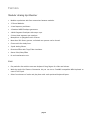
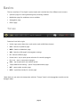
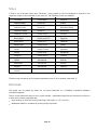
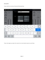
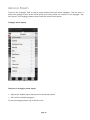
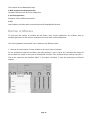
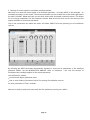
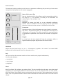
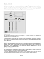
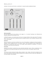
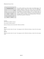
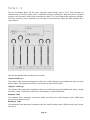
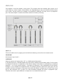
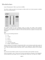
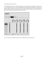
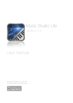
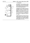
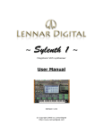
!
Tera Synth
!
!
Modular Analog Synthesizer
!
!
!
!
!
!
!
!
!
!
!
!
!
!
!
!
!
!
!
!
!
!
VirSyn Software Synthesizer
!
!
Introduction....................................................................................5
Welcome to Tera Synth................................................................................................5
Features......................................................................................................................6
Basics..............................................................................................8
Top bar.......................................................................................................................8
Interfaces....................................................................................................................9
Keyboard Bar..............................................................................................................9
Scale.........................................................................................................................10
Keyboard..................................................................................................................10
Sound Presets...........................................................................................................11
Arpeggio Presets.......................................................................................................13
Audio Recordings......................................................................................................14
Audiocopy / SoundCloud..........................................................................................14
Synthesis.......................................................................................15
Modular Analog Synthesis.........................................................................................15
Routing of Modules...................................................................................................16
Keyboard..................................................................................................................18
Oscillator 1...............................................................................................................19
Oscillator 2...............................................................................................................21
Oscillator 3...............................................................................................................23
WaveGuide................................................................................................................25
Ringmodulator..........................................................................................................27
Noise Generator........................................................................................................28
Subharmonic Oscillator.............................................................................................28
Mixer........................................................................................................................29
Filter 1 / 2................................................................................................................30
Formant Filter...........................................................................................................32
Amplifier...................................................................................................................34
page 2
Modulation....................................................................................36
Low Frequency Oscillators (LFO)................................................................................36
Standard Envelopes...................................................................................................38
Multi Envelopes.........................................................................................................41
Arpeggiator...................................................................................44
Overview...................................................................................................................44
Global Settings..........................................................................................................45
Step Matrix Editor.....................................................................................................47
Effects...........................................................................................48
Distortion.................................................................................................................48
Phaser.......................................................................................................................49
Delay........................................................................................................................49
Chorus......................................................................................................................49
Reverb......................................................................................................................50
Appendix......................................................................................51
Troubleshooting.......................................................................................................51
page 3
!
page 4
Introduction
!
WELCOME TO TERA SYNTH
Explore new sound spaces with Tera Synth that go beyond the emulation of synthesizer legends. Use the
power of analog and digital synthesis combined with new modules for physical modelling. Wireless
patching of modules combined with an intelligible modulation routing simplifies the development of
new synthesizer designs from scratch. Distortion effect, Delay/Chorus/Phaser and Reverb effects give
your sounds the final polishing. Tera Synth gives your music an individual character with its unique fat
sound. The well-designed algorithms and the economical modular structure provides you with a
comparatively high voice yield. Precise timing with the unique built-in Arpeggiator let you feel the
rhythm.
!
Tera Synth supports Audiobus and Inter-App-Audio for integration with other Music Apps.
With the Apple iPad Camera Connection Kit you can use a CoreMIDI compatible MIDI Keyboard to control
Tera Synth from external hardware equipment.
For updated informations about Tera Synth please visit our website at mobile.virsyn.com.
!
!
page 5
FEATURES
!
Modular Analog Synthesizer
!
•
Modular synthesizer with free connections between modules.
•
25 Sound Modules.
•
4 Low frequency oscillators. •
4 Standard ADSR Envelope generators.
•
4 Multi Segment Envelopes with tempo sync.
•
64 time/level segments per envelope.
•
Monophonic or polyphonic with 8 voices.
•
More than 920 factory presets, unlimited user presets can be shared. •
Chorus with four delay lines.
•
8 pole Analog Phaser.
•
Distortion Effect with Tape/Tube simulation.
•
Stereo Echo/Delay Effect
•
Hi end reverberation unit.
•
Play melodies live with the onscreen keyboard. Drag fingers for slides and vibrato. •
With the Apple iPad Camera Connection Kit you can use a CoreMIDI compatible MIDI Keyboard to
control Tera Synth.
•
Select from dozens of scales and play them with scale optimised keyboard layout.
!
Live
!
!
page 6
Full featured programmable Arpeggiator
!
•
Uses programmable sequences with up to 32 steps. •
Can trigger single notes and chords.
•
Unique randomizer generates Arpeggios with 100% usability.
•
32 Arpeggios included, unlimited user arpeggios possible.
•
For each step you can program tie, accent, transposition and note order
•
Audiobus compatible ( Output ).
•
Inter App Audio compatible.
•
Audio pasteboard for exchange with other Apps
•
Exchange user presets with File Sharing in iTunes.
•
Support for virtual MIDI input connections.
•
MIDI Learn function for parameters.
•
Publish recordings online with the SoundCloud audio platform.
•
Exchange user presets with File Sharing in iTunes.
!
Global
!
page 7
Basics
The user interface of Tera Synth is quite simple and is divided into four different main screens:
•
Synthesis page for sound generating and processing modules
•
Modulation page for modulator source modules
•
Arpeggiator page
•
Effects page
!
TOP BAR
!
Functions from left to right:
•
VirSyn Logo opens About box ( and can be used as MIDI Panic button )
•
SYN - Switch to Synthesis page.
•
MOD - Switch to Modulator page.
•
ARP - Switch to ARP page for Arpeggiator settings
•
FX - Switch to Effects page
•
Preset name - tap to open preset selection for sounds/arpeggios
•
Disc icon - tap to save preset/arpeggio
•
Dice - tap to generate a new random preset.
•
Tempo/Metronome setting - opens Tempo/Metronome page*
•
REC - opens audio recorder page
•
HELP - open help overlay for current page.
!
*Note that you can enter the tempo also with the “Tempo” knob in the Arpeggiator module on the
arpeggio page.
page 8
INTERFACES
!
!
KEYBOARD BAR
!
•
Q - If Key Quantize is set: swiping over the keys is constrained to exact tuning (Glissando), otherwise
pitch bends continuously (Glide). •
MIDI - Sets the MIDI channel Tera Synth is listening for MIDI Notes coming from an external
Keyboard or from another App connected via virtual MIDI.
•
Scale - select the key and the scale used by the keyboard ( see below for details )
•
Keyboard range - Tap to select keyboard range, double tap to size the keyboard.
•
HOLD - If set all keys tapped remain on until tapped again. Good to hold notes while designing
sounds. •
BKGD AUDIO - If set Tera Synth doesn’t stop working if running in the background. This let you for
example have a sequencer App in the foreground and Tera Synth working in the background. !
Please note that the full keyboard bar with all parameters is only visible in the FX page.
!
!
page 9
SCALE
If Scale is set to another value than 'Chromatic', notes played on the live keyboard or entered in the
sequencer 'snap' to notes allowed by the scale set. The following scales are available: Chromatic
Chord Major
Algerian
Diatonic Major
Chord (m)
Arabic
Diatonic minor
Chord (6)
Bali Island Pelog
Pentatonic Major
Chord (7)
Byzanthine
Pentatonic minor
Chord (maj7)
Chinese
Blues Major
Chord (maj7+5)
Egyptian
Blues minor
Chord (m7)
Hawaiian
Whole-tone
Chord (sus4)
Hindu
Ionian
Chord (7sus4)
Japanese
Dorian
Chord (dim)
Mongolian
Phrygian
Chord (dim7)
Oriental
Lydian
3rd Interval
Persian
Mixolydian
4th Interval
Ryukyu
Aeolian
5th Interval
Spanish
Locrian
!
The base note transposes all live played/sequenced notes if set to another value than 'C'.
!
KEYBOARD
Tera Synth can be played by either the on-screen keyboard or a CoreMIDI compatible Hardware
controller keyboard.
The on-screen keyboard seems to miss a pitch bender / modulation wheel but this functions are there in
a more touch screen compatible way:
•
Pitch bending is done with moving the fingers left/right. ( if “Q” is not set )
•
Modulation wheel is simulated by moving fingers up/down.
!
!
page 10
SOUND PRESETS
The presets in Tera Synth are organised in eight predefined sound categories.
Tap on the preset name in the top bar to open a popup window with a list of all available presets.
!
Popup window for presets:
!
!
Import/Export of sound presets:
The presets are saved as files with the extension “.fxp” and they can be directly accessed within the
iTunes File Sharing section of the App. Download the folder “presets” in the App section of the iTunes
File sharing. Then you’ll find all presets in the subfolders named “Leads”, “Bass”, and so on. To import a
preset just upload the preset files you want to import in the iTunes File sharing section. They will then
automatically imported by Tera Synth with the next start of the App.
page 11
Save preset:
!
Tap on the Disc Icon and you’ll get the following dialog:
!
!
!
Tap on the category you want this sound to be in and name the preset to your liking.
page 12
ARPEGGIO PRESETS
Touch on the “Arpeggio” field to open a popup window listing all preset arpeggios. The first entry is
always the arpeggio in the current sound preset since every preset can contain it’s own arpeggio. “Arp
from preset” is the arpeggio pattern saved inside the current sound preset.
!
Arpeggio preset popup: !
!
Functions in Arpeggio preset popup:
!
•
Right arrow: window opens where you can rename the pattern
•
Edit: use this to delete arpeggios. To save an Arpeggio pattern tap on the Disc Icon.
page 13
AUDIO RECORDINGS
Tap on the record button (red circle) in the top bar to bring up the Audio Recorder popover which let you
enter the recorder settings and you can start recording of audio from here:
!
Recording starts after a count-in of one bar indicated by the
metronome and stops with the next tap on “REC”. Start the recording
with a tap on the “Record” button.
The recorded audio is saved in a wave file with the preset name set as
default file name. You can access the the files in the iTunes File
sharing folder for Tera Synth.
In addition the midi note on/off information coming from playing the
onscreen or external keyboard is recorded into a file with the same
name and the file extension “.mid”. If the arpeggiator is active the
notes from the arpeggiator are recorded in the MIDI file.
To change the file name just tap on the name field and enter the new
file name.
Tap on the right arrow of an existing recording in the list to replay it.
!
!
!
!
!
AUDIOCOPY / SOUNDCLOUD
The recorded audio can also be copied into the Audio Pasteboard and uploaded to SoundCloud in this
Popup. Just select the recording in the list and tap on “SoundCloud” or “Clipboard”.
page 14
Synthesis
!
MODULAR ANALOG SYNTHESIS
The modular synthesizer uses independent sound generating and processing modules. The modules are
not hardwired together but can be freely connected together using virtual wires (patch cords).
These modules can be accessed on the Synthesis (SYN) Page and on the Modulation (MOD) page of Tera
Synth divided by their main usage as sound generating/processing and modulation source.
Tap on a free in the modules pane and drag left/right to reveal more modules.
!
The modules on the Synthesis Page:
Keyboard
Master tuning / Portamento.
Oscillator 1
Main oscillator with wave modulation.
Oscillator 2
Oscillator with wave modulation and FM input.
Oscillator 3
Oscillator with FM input.
Ringmodulator
Multiplication of two input signals.
Noisegenerator
White and Red noise.
Wavemixer
Mixer 3 + 2 in 1.
2 Multimode filter
Filter with adjustable slope ( 24/18/12 dB) and characteristic ( Lowpass / Highpass / Bandpass /
Bandreject ).
Formant filter
3 Bandpass or bandreject filter for formant sounds and phasing effects.
WaveGuide
Physical modelling for simulating string and wind instruments.
Amplifier
Final amplifier with overdrive and LoFi effects.
!
!
page 15
The modules on the Modulation Page:
4 Multi segment envelope generator
syncable Envelopes with up to 64 breakpoints.
4 Envelope generator
Envelopes with D-ADSR characteristic.
4 LFO
Low frequency oscillator with synchronisation and Sample&Hold function.
!
ROUTING OF MODULES
To show you the routing of modules we will build a very simple synthesizer: An oscillator with an
envelope generator for the volume envelope as the most basic sound modulation.
!
The routing between the modules can be made on two different levels:
!
1. Routing of sound output of some module to the sound input of another.
For our example we need one oscillator ( we take Oscillator 1, but it can be any ) and want the output of
this oscillator be routed to the input of the Amplifier module ( This module must be used by any patch ).
Tap on the connection box labelled “INPUT 1” and select “Oscillator 1” from the upcoming list of Sound
outputs:
!
!
page 16
!
2. Routing of control signals to modulate sound parameters. Next step is to route the control signal of an envelope generator - let’s take ADSR1 in this example - to
modulate the volume of the sound. The Volume parameter can be set with the circular knob right above
the label “VOLUME”. Below the knob you see three sliders with associated connection boxes. This allows
for up to three modulations for the parameter Volume. Now we use the first one for the routing of the
output of ADSR1 to the Volume parameter:
Tap on the connection box below the slider and select ADSR1 from the upcoming list of modulation
sources:
By selecting the ADSR the dialog automatically expands to show you all parameters of the envelope
generator ADSR1. Set the MODULATION AMOUNT slider to maximum - this sets the amount of
modulation the envelopes applies to the volume parameter.
You will find this schema:
• Circular knob adjusts parameter value
• One or more slider(s)/connection box(es) for routing of modulation sources on most parameters of Tera’s modules.
!
Now you’re ready to play some notes with the first synthesizer you’ve just crafted !
!
!
page 17
KEYBOARD
The keyboard module provides you with access to parameters influencing the processing of note events
coming from the Keyboard or the internal arpeggiator.
!
Master Pitch coarse/fine
Sets the absolute pitch for all oscillators and the waveguide module in
the range of +/- 24 semitones if tracking is set. Otherwise the
absolute pitch of the oscillator is set.
Pitch Mod
Modulate the master pitch with up to two selectable modulation
sources. Select a modulation source by tapping into the square field
below the slider and set the amount of modulation with the slider. Portamento
Smooth transition of the pitch between two notes played in succession.
The time to reach the final pitch can be adjusted in the range of 0
milliseconds to 70 seconds. This effect is typical for many lead sounds
on monophonic synthesizers, but can also be used here in polyphonic
mode.
Fingerd
In normal mode all notes played will have the portamento effect. In
fingered mode only legato-played notes will have this effect.
!
!
MIDI Bend
Adjusts the pitch bend range ( up to +/- 48 semitones ) applied to the sound if an external MIDI
Keyboard with a Pitch bender control is connected to Tera.
Poly
Here you can limit the maximum number of voices which can be played simultaneously.
You can select between:
• monophonic
• mono/legato
• polyphonic
Phase
With “Free Phase” all oscillators are running freely. This has the effect that the same note value played
repeatedly can sound slightly different from each other. This is the preferred mode for most sounds.
With “Sync Phase” the oscillators starts synchronously on each note start. Then repeated notes all sound
equal. This is the preferred mode for drum sounds. Note that this mode can lead to clicks in the onset of
sounds.
page 18
OSCILLATOR 1
Oscillators provides you with the base material for sound synthesis. They generate periodic oscillations
of analog and digital waveforms with controllable frequency. The oscillators in Tera use anti-aliasing
algorithms to produce waveforms without digital distortion even in the highest register. Nevertheless,
Tera’s oscillators provide you with an outstandingly fat sound in the lower registers.
Pitch coarse/fine
Sets the relative pitch for this oscillators in the range of +/- 4 octaves if tracking is set. Otherwise the
absolute frequency of the oscillator is set.
If FM RATIO button is set, then the pitch can be set in integer multiples of the master pitch. The range is
from 1:1 to 1:17. This mode is especially suited for setting the typical carrier/modulator frequency ratios
used in FM synthesis.
Waveform
Select the waveform used by the oscillator from a list of 64 waveforms including the classical waveforms
sawtooth, square, triangle and sine. If you select “Custom” from the waveform menu a dialog pops up
where you can specify the level of up to 256 partials which determine the waveform. To open the
waveform list just tap on the module box.
PM - Phase modulation
With phase modulation activated (Button PM) the oscillator’s output is added to a phase shifted copy of
itself. The phase shift is controlled by the phase modulation knob. If you select the waveform sawtooth then the result is a pulse waveform with variable pulse width. In
contrast to traditional pulse implementations you can use this for all the available waveforms.
page 19
Below the Phase knob you find a slider/selector combination to modulate the phase with one of the
many possible modulation sources.
Pitch Mod
Modulate the oscillator’s pitch with up to two selectable modulation sources. Select a modulation source
by tapping into the square field below the slider and set the amount of modulation with the slider.
Track
This button activates keyboard tracking. When switched on the oscillator will track the keyboard at the
rate of one semitone for each key. When switched off the oscillator will have a fixed pitch independent of
the notes played on the keyboard.
6x - Spread
To make wonderful fat and powerful supersaw like sounds you need several oscillators tuned nearly in
unison. Just tap the 6x button and Oscillator 1 will then output six detuned waves concurrently. The
amount of detuning between this six oscillators can be adjusted with the “Spread” knob.
!
!
!
page 20
OSCILLATOR 2
In addition to the functions of Oscillator 1 this one has a linear FM input for FM synthesis.
Pitch coarse/fine
Sets the relative pitch for this oscillators in the range of +/- 4 octaves if tracking is set. Otherwise the
absolute frequency of the oscillator is set.
If FM RATIO button is set, then the pitch can be set in integer multiples of the master pitch. The range is
from 1:1 to 1:17. This mode is especially suited for setting the typical carrier/modulator frequency ratios
used in FM synthesis.
Waveform
Select the waveform used by the oscillator from a list of 64 waveforms including the classical waveforms
sawtooth, square, triangle and sine. If you select “Custom” from the waveform menu a dialog pops up
where you can specify the level of up to 256 partials which determine the waveform. To open the
waveform list just tap on the module box.
PM - Phase modulation
With phase modulation activated (Button PM) the oscillator’s output is added to a phase shifted copy of
itself. The phase shift is controlled by the phase modulation knob. If you select the waveform sawtooth then the result is a pulse waveform with variable pulse width. In
contrast to traditional pulse implementations you can use this for all the available waveforms.
Below the Phase knob you find a slider/selector combination to modulate the phase with one of the
many possible modulation sources.
page 21
Pitch Mod
Modulate the oscillator’s pitch with up to two selectable modulation sources. Select a modulation source
by tapping into the square field below the slider and set the amount of modulation with the slider.
Track
This button activates keyboard tracking. When switched on the oscillator will track the keyboard at the
rate of one semitone for each key. When switched off the oscillator will have a fixed pitch independent of
the notes played on the keyboard.
FM-Input
With this input you can modulate the oscillator frequency with the output signal of another module, for
example a filter or an oscillator. The amount of the modulation, called Modulation index in FM synthesis
terminology, can be adjusted in the the range of 1 to 16.
FM-Index
The modulation index can be modulated with up to two selectable modulation sources. Select a
modulation source by tapping into the square field below the slider and set the amount of modulation
with the slider.
!
page 22
OSCILLATOR 3
Oscillator 3 has the same functions as Oscillator 2, except the phase modulation feature.
Pitch coarse/fine
Sets the relative pitch for this oscillators in the range of +/- 4 octaves if tracking is set. Otherwise the
absolute frequency of the oscillator is set.
If FM RATIO button is set, then the pitch can be set in integer multiples of the master pitch. The range is
from 1:1 to 1:17. This mode is especially suited for setting the typical carrier/modulator frequency ratios
used in FM synthesis.
Waveform
Select the waveform used by the oscillator from a list of 64 waveforms including the classical waveforms
sawtooth, square, triangle and sine. If you select “Custom” from the waveform menu a dialog pops up
where you can specify the level of up to 256 partials which determine the waveform. To open the
waveform list just tap on the module box.
Pitch Mod
Modulate the oscillator’s pitch with up to two selectable modulation sources. Select a modulation source
by tapping into the square field below the slider and set the amount of modulation with the slider.
Track
This button activates keyboard tracking. When switched on the oscillator will track the keyboard at the
rate of one semitone for each key. When switched off the oscillator will have a fixed pitch independent of
the notes played on the keyboard.
page 23
FM-Input
With this input you can modulate the oscillator frequency with the output signal of another module, for
example a filter or an oscillator. The amount of the modulation, called Modulation index in FM synthesis
terminology, can be adjusted in the the range of 1 to 16.
FM-Index
The modulation index can be modulated with up to two selectable modulation sources. Select a
modulation source by tapping into the square field below the slider and set the amount of modulation
with the slider.
!
page 24
WAVEGUIDE
This module is the basic building block for physical modelling synthesis. First of all it sums the signals
from its two audio inputs (INPUT and FEEDBACK), and is attenuated by the input knob and the feedback
knob settings. The sum is then delayed with a pitch synchronous delay time and low-pass filtered with
an adjustable cutoff frequency. In the simplest form one can use this module as a delay line with realtime control of the delay time.
!
But how can we make a physical model of an instrument with this delay line ?
To simulate the travelling wave of a string or an air tube the output of the delay line has to be patched to
the FEEDBACK Input to get a closed feedback loop. This loop needs some initial energy put into INPUT to
resonate and thereby produce a sound. To accomplish this, patch some oscillators or the noise
generator to INPUT and modulate the input level by a very short attack/decay envelope. The spectrum of
this input signal strongly determines the resulting sound in a very interesting manner: the resulting
sound is filtered by the spectrum of the input signal ! If, for example, a mix of three sine tones with fixed frequencies are used as excitation sources the
resulting output sounds like a formant filter with three bandpass filters having fixed centre frequencies
and infinite slopes. The built-in loop filter (6dB lowpass) corresponds to the damping of high frequencies in the physical
model. Due to this loop filter higher harmonics decay much faster than lower harmonics. With the cutoff
frequency set to 0 you get the typical sound of plucked strings, like a guitar. For steady state sounds you
should set the cutoff frequency to maximum.
!
page 25
In the physical model the source for the FEEDBACK input is usually the WaveGuide output simulating the
reflection of the travelling wave on both ends of a string or tube. But you can choose any audio source if
you want to use this module for other purposes. The input level is controlled in an unusual manner by
the feedback slider. This slider gives you control over the decay time of the sound in the range of 50 ms
to 200 seconds. Negative values simulate the travelling wave of a tube with one open end and one
closed end resulting in a hollow, square-like sound. In this case the pitch is one octave lower than for
positive feedback values.
INPUT
Choose an audio source for the initial energy impulse by clicking into this field and selecting a source
from the popup menu.
LEVEL
Adjusts the level for Input 1. Modulate this input with a short attack/decay envelope to simulate the
injection of an energy impulse.
FEEDBACK INPUT
Second input for the delay line. The input level can be adjusted with the feedback slider. For physical
modelling synthesis the WaveGuide output has to be patched to this input.
TRACK
This button activates keyboard tracking. When switched on the WaveGuide will track the keyboard at the
rate of one halftone for each key. When switched off the WaveGuide will have a fixed pitch independent
of the notes played on the keyboard.
COARSE
Coarse tuning of the oscillator relative to the master tuning adjusted in the keyboard module within a
range of +/- 48 semitones.
FINE
Fine tuning of the pitch in the range of –50 to +50 cent with variable resolution from 0.02 cent to 2.0
cent for one slider increment. ( 100 cent = 1 halftone step )
CUTOFF
Controls the cutoff frequency of the loop filter (6dB lowpass). Low cutoff values lead to faster decay of
the higher harmonics compared to the lower harmonics. In addition the decay time of all harmonics is
always proportional to the pitch and influenced by the feedback slider.
FEEDBACK
Adjusts the level for the feedback input. If the WaveGuide output is patched to the feedback input you
get a closed loop with the feedback slider controlling the decay time of the sound in the range of 50 ms
to 200 seconds
!
!
page 26
RINGMODULATOR
This module combines two input signals by multiplying them. The
resulting spectrum contains the sum-of and the differencesbetween the frequency components of the two input signals. When
the frequency of one input signal is below 20 Hz the result is a
tremolo effect. But when the frequency is in the audible range the
result is a change in timbre. If the pitch of the input signals are in
an integer ratio to one another, the resulting spectrum is harmonic,
otherwise the spectrum is inharmonic. !
!
!
Example: Sine tone with 1000Hz at input 1
Sine tone with 300Hz at input 2
Result on Output: two sine tones with 1300Hz and 700Hz.
!
INPUT 1
Choose an audio source for input 1 by tapping into this field and selecting a source from the popup
menu.
INPUT 2
Choose an audio source for input 2 by tapping into this field and selecting a source from the popup
menu.
!
!
page 27
NOISE GENERATOR
The noise generator provides you with two different types of noise. Use the noise generator to produce
sounds simulating wind, ocean breakers or unpitched drums:
White noise
The spectrum of white noise contains all frequencies with equal power. It sounds very bright and sharp.
Pink noise
Lowpass filtered white noise. The lowpass filter has a fixed cut-off frequency of 0 Hz and a slope of
3dB/octave. Pink noise sounds darker and smoother than white noise.
Every voice in Tera has its own noise generator to avoid undesirable correlations when many voices are
sounding simultaneously.
There are no user interface elements for the noise generator. The module appears only in the menu of
the module inputs as one of the selectable sound sources.
!
SUBHARMONIC OSCILLATOR
!
Oscillator 1 has an additional output for subharmonic sounds. The pulse width of this sound is always
controlled by the wave modulation slider, even if wave modulation is deactivated. The subharmonic
sound is a mix of six pulse oscillators with a frequency ratio of 1:2:3:4:5:6.
This module is inspired by Oskar Sala’s Mixtur-Trautonium and the Ondes Martenot, both legendary
instruments created in the beginning of the 20th century.
!
page 28
MIXER
With this module you can mix down up to 5 input signals to the mix outputs.
!
The three outputs of the wave mixer provides you with the following sub mixes:
Mix 1-3
Mix of the signals on input 1 to 3.
Mix 4-5
Mix of the signals on input 4 and 5.
Mix
Mix of all input signals.
Mix (hidamp)
Mix of all input signals with a filter to damp high frequencies.
Therefore you can also use this mixer as two independent mixers with, respectively, 2 and 3 inputs.
INPUT 1-5
Choose the audio source for the inputs 1 to 5 by tapping into the appropriate field and selecting an
audio source from the popup menu.
page 29
FILTER 1 / 2
The two multimode filters are the most important sound design tools in Tera. They simulate the
characteristics of the filter types used in traditional analogue synthesizers. With the built-in overdrive
you get a soft distortion. Several filter characteristics with 12, 18 and 24 dB/octave slopes are available.
The filter resonance can be adjusted up to the level of self-resonance, where the filter behaves like a
sine oscillator.
!
Here are the available filter characteristics in detail:
Lowpass 24dB Typ I
The lowpass filter attenuates frequencies above the cutoff frequency with 24dB/octave giving a warm
and fat sound. The design of this filter is also known as “State variable filter”.
Highpass 24dB Typ I
The highpass filter attenuates frequencies below the cutoff frequency with 24dB/octave giving a bright
and sharp sound. The design of this filter is also known as “State variable filter”.
Bandpass 12dB
The bandpass filter attenuates frequencies below and above the cutoff frequency with 12dB/octave
giving a nasal and thin sound.
Bandreject 12dB
The bandreject filter attenuates frequencies near the cutoff frequency with 12dB/octave giving a phaser
like sound.
!
page 30
Lowpass 12dB
The lowpass filter attenuates frequencies above the cutoff frequency cutoff with 12dB/octave giving a
warm and natural sound.
Highpass 12dB
The highpass filter attenuates frequencies below the cutoff frequency with 12dB/octave giving a bright
and thin sound.
Lowpass 24dB Typ II
This lowpass filter has a classical cascade design and attenuates frequencies below the cutoff frequency
with 24dB/octave giving a warm and dark sound.
Lowpass 18dB Typ II
This lowpass filter has a classical cascade design and attenuates frequencies below the cutoff frequency
with 18dB/octave giving a 303 like sound.
!
The filter parameter in detail:
INPUT
Choose an audio source for input 1 by clicking into this field and selecting a source from the popup
menu.
Filter type
Selection of the filter characteristic. tap in the filter box for selection menu.
DRIVE
Adjusts the filter input level in the range of –10dB to +30dB. Actual input levels above 0dB results in a
soft distortion of the input signal. Note that with increasing input level the filter resonance fades.
TRACK
Adjusts the keyboard tracking of the filter cutoff frequency. With a value of 1 the keyboard will control
the cutoff frequency at a rate of one halftone per key. With a value of 0 keyboard tracking is off.
CUTOFF
Adjusts the filter cutoff frequency. For a lowpass filter higher values result in brighter tones and lower
values result in darker tones. The range is from 20Hz to 20kHz. The cutoff frequency which is shown in
the info window below the cutoff slider is the value for the key A4 (440Hz) if keyboard tracking is active.
RESONANCE
Adjusts the filter resonance which emphasizes frequencies close to the cutoff frequency. With very high
values the filter will start to oscillate itself, producing a sine wave.
SHIFT
Each filter is internally built by two or more sub-filters connected in series. This parameter shifts the
cutoff frequency of these subfilters. The effect depends on the filter characteristic:
Lowpass
Highpass
Bandpass
Bandreject
adjusts
adjusts
adjusts
adjusts
the
the
the
the
slope of the filter
slope of the filter
bandwidth of the passband
bandwidth of the stopband
This parameter has no effect for the filter types Lowpass 12dB and Highpass 12dB.
!
page 31
FORMANT FILTER
The Formant filter contains three independent filters which can be used in two different configurations:
3 band pass filter in parallel
Formant filter for fixed and dynamically controllable formants. This configuration is useful for simulating
vocal sounds and for filter morphing.
3 band reject filter in series
This filter configuration results in sounds comparable to comb filters and phaser effects useful for
„spacey“ sounds. As opposed to common fixed filter banks, with this one you can dynamically control all filter parameters
using different modulation sources !
INPUT
Choose an audio source for input by tapping into this and selecting a source from the popup menu.
Peak filter/Notch filter
Switches the filter configuration between „parallel bandpass“ and „serial band reject“ filters. DEPTH
The depth parameter controls the mix of the filtered and the original input signal. The range is from 0.0
to 1.0. With depth set to 1.0 only the filtered signal is sent to the output. With depth set to 0.0 only the
original signal is sent to the output.
!
!
page 32
FREQU 1 .. 3
Adjusts the centre frequency of the peak/notch filters. All frequencies below and above the centre
frequency will be attenuated for the bandpass filter. All frequencies around the centre frequency will be
attenuated for the bandreject filter. The range is from 20 Hz to 20000 Hz.
Q 1 .. 3
Adjusts the bandwidth of the bandpass filter relative to the centre frequency:
bandwidth [Hz] = center frequency [Hz] / resonance
The range is from 0.5 to 512. For a centre frequency of 1000 Hz this results in a bandwidth ranging
from 2000 Hz to 2 Hz.
L 1 .. 3
The output level for the bandpass filter relative to the other two bandpass filters. The range is from –50
dB to +20 dB.
!
!
page 33
AMPLIFIER
The amplifier is the last module in every patch. This module mixes the selected input sources of all
voices down to a stereo output. All parameters act independently on every voice before the final stereo
mix is done. The pan position for example, can therefore be different for every voice in a polyphonic
part. The stereo output is routed to the effects section for further processing. !
INPUT 1/2
Choose an audio source by tapping into this field and selecting a source from the context menu.
CROSSFADE
Mix between input 1 and 2
OVERDRIVE
Adjust the amount of ranging from „Off“ to +64dB (maximal distortion).
A soft distortion unit is inserted between the input of the amplifier and the volume slider. For this reason
the degree of distortion is independent of the volume setting. If the volume is modulated by an envelope
generator – as in most sound programs – the degree of distortion is also independent of the dynamic
envelope. If you modulate the amplitude with an envelope generator before the signal goes into the
amplifier unit then the degree of distortion varies with the dynamic envelope just as usual. Every voice
has its own distortion unit, so there’s no inter-modulation between the notes in polyphonic play.
Therefore the sound is quite different in comparison to a standard distortion unit. !
!
page 34
VOLUME
Output level ranging from –40dB to +40dB
PAN
Adjusts the position of the sound in the stereo panorama. Opposed to the pan slider in the part mixer
this one works independently for each voice ! If for example the pan is modulated by an LFO this means
every voice can have an independent position.
DIRECT LEFT/RIGHT inputs
These two inputs are routed directly to the stereo output of the amplifier. This makes it possible to
produce stereophonic patches directly in the synth patch.
page 35
Modulation
LOW FREQUENCY OSCILLATORS (LFO)
Tera Synth provides you with four low frequency oscillators which can be freely assigned to modulate
one or more sound parameters.
This module provides you with oscillations useful for periodic and random sound parameter
modulations. The LFO can produce seven different modulation waveforms. Every LFO can also be used to
Sample & Hold the waveform of another LFO. The rate of the LFO can be synced to the tempo of the
Arpeggiator.
Wave
Selects one of the following waveforms:
2.1. Sine
2.2. Triangle
2.3. Square
2.4. Ramp up
2.5. Ramp down
2.6. S & H (Sample & Hold)
2.7. Random - Aperiodic waveform.
Using the waveform S & H produces a Sample & Hold effect. In this mode the module takes samples of
the output of the next LFO at the rate of the LFO frequency. For Example LFO 2 takes samples from LFO
1. To create the traditional Sample & Hold effect select a random modulation waveform for the sampled
LFO.
Wave
Sets the rate of the modulation oscillator. The rate of the oscillator can be specified in two ways:
If the Sync parameter is set to “Tempo sync’d” then the rate depends on the tempo of the Arpeggiator.
Then you specify the cycle length in terms of note length with a range from 1/32 triplet to 4/1 dotted.
page 36
Otherwise the rate can be specified in a range from 1 cycle every 100 seconds to 689 cycles / second.
Sync
Sets the LFO phase and rate synchronisation. The following modes are available:
Common
- All voices of a part are modulated in sync.
Tempo Sync’d - The rate is synced to the tempo of the internal Arpeggiator Random - Every voice has its own LFO starting with random phase on key down. The modulation is therefore phase-shifted for every voice of a polyphonic chord.
Key - Every voice has its own LFO starting with zero phase on key down.
!
!
!
page 37
STANDARD ENVELOPES
The envelope generator lets you shape the parameters of a sound over time, beginning from when a key
is hit, continuing as the key is held, and adjusting how the sound decays after the key is released. You
can also trigger the envelope by one of the four LFOs instead of hitting a key. TERA uses envelopes with
ADSR characteristic (like most analogue synthesizers do), extended by a delay phase and the option to
thicken short attack/decay envelopes with the punch option.
!
For every single voice TERA provides you with four independent envelope generators.
!
page 38
This is how the envelope evaluates after triggering:
Modulation
depth
1
Sustain level
Delay
Attack
Decay
Sustain
Release
Key pressed
Key released
!
time
!
!
!
!
!
!
!
!
!
!
!
!
!
DELAY
Sets the delay time between note triggering and the start of the attack phase. Range is from 0.7 ms to
132 seconds.
ATTACK
Sets the time the envelope needs to reach the maximum level. The curvature is logarithmic, which means
that from the start the signal builds up quickly and slowly rises when approaching the maximum level.
Range is from 0.7 ms to 132 seconds.
DECAY
Sets the time the envelope needs to reach the sustain level after the attack phase has ended. The
curvature is exponential, which means that from the start the signal decays quickly and slowly falls when
approaching the sustain level. Range is from 0.7 ms to 132 seconds. The decay time has no effect if the
sustain level is set at maximum.
SUSTAIN
Sets the sustain level the envelope will stay until release. Range is from 0 to 1.
RELEASE
Sets the time the envelope needs to reach the level 0 after the key is released. The curvature is
exponential, which means that from the start the signal decays quickly and slowly falls when
approaching the level 0. If the release time is set to 0 then the release time automatically follows the
decay time. This results in an Attack/Delay only envelope.
PUNCH
The punch switch delays the start of the decay phase by a few milliseconds. The result is a „thicker“
attack similar to a compressor effect. This effect is audible only on short attack/decay time envelopes.
!
page 39
Trigger mode With the trigger mode you decide when and how the envelope is triggered. The following modes are
available:
KEY
The envelope starts on key down with the last actual level.
KEY RESET
The envelope starts on key down with the level 0.
KEY ONCE
Like Key trigger, but the envelope won’t start with legato played notes.
LFO 1
The envelope starts with every new cycle of LFO 1.
LFO 2
The envelope starts with every new cycle of LFO 2.
LFO 3
The envelope starts with every new cycle of LFO 3.
LFO 4
The envelope starts with every new cycle of LFO 4.
!
page 40
MULTI ENVELOPES
Tera Synth provides you with four multi segment envelopes which can be freely assigned to modulate
one or more sound parameters.
These envelopes have up to 64 time/level segments giving you all from simple Attack/Decay style
envelopes up to complex rhythmical patterns which can even be synchronised to MIDI tempo.
The four envelopes are completely independent from each other: They can have different number of
segments with free time/level values.
The main envelope editor figured below provides you with a context menu for copying and pasting
envelopes through the clipboard and for selecting them from about 64 predefined envelopes.
!
Editing the envelopes is an easy and straightforward process:
You can change the time or level of any segment by dragging the small yellow circle at the end of each
segment into the desired position. Clicking the small black dot within the segment changes the slope. All
editing take effect immediately!
With this dragging you also have selected this segment and then you can use alternatively the value
fields for delta, level and slope for editing these values. Tap into the appropriate value field and drag
your finger up or down for changing the values.
To insert a new segment/delete an existing one first tap on the "Insert/Delete" Button to switch mode
and then tap the segment you want to insert/delete.
!
page 41
The two grey vertical lines are the loop marker positions for the envelope. They are managed
automatically by Tera Synth. The looping of the envelope between these two lines come automatically in
effect as soon as more than one envelope segment is inside the marker positions.
You can scroll and zoom in the envelope window concurrently by tapping on the time bar below the
envelope window and drag up/down for zooming and drag left or right for scrolling in the window.
If you want to edit a segment without changing the positions of other segments switch off the slide
mode with a tap into the mode field above the envelope.
To create tempo synchronised envelopes tap into the sync field which will show then the value “On” and
the time bar will show you then note values instead of absolute time.
!
page 42
!
!
page 43
Arpeggiator
!
OVERVIEW
Tera Synth features an arpeggiator with a very flexible step matrix editor for programming and a unique
“rolling dice” random arpeggio generator. Every sound preset can store it’s own arpeggio pattern. You
can build arpeggios from scratch or use one of the 32 preset arpeggios as foundation. You can also
create an unlimited number of user arpeggio presets.
!
Just play a chord or a single note and it gets transformed into a grooving monophonic synth line or a
rhythmical chord pattern.
!
page 44
GLOBAL SETTINGS
Tap on the arpeggio button to start/stop the arpeggio.
The mode parameter determines the way the pressed keys are sequenced. Available modes are: Up/
Down/Alternate/Random/Incl/Excl.
!
The trigger parameter controls the way pressed notes and chords are handled:
standard – all currently pressed notes are used for the arpeggio.
hold – the last pressed notes are taken and the arpeggio continues even after you lift of all notes.
key sync – like “standard, but the arpeggio restarts at step 1 with every new press of some notes. !
The clock parameter sets the basic step length.
The Tempo can be set in bpm (40-300) with the tempo knob. To enter a tempo value by tapping a
rhythm tap on the tempo display in the top bar of the main window. !
With Shuffle every other step in the arpeggio is moved forward or backward in timing.
The fix parameter is a performance function and if on the global settings of the arpeggio don’t change
on sound or arpeggio preset selection. This is useful if you want to use different arpeggios for one
sound or different sounds for one arpeggio with the same settings. Note that if fix is on the selection of another preset doesn’t load the presets own arpeggio, the currently
active arpeggio stays as it is.
!
page 45
Some more parameter are available on the right side of the Arpeggio page:
!
With the “rolling dice” you can get another randomly generated arpeggio with each tap on the dice and
be surprised how useful they can be !
The gate parameter controls the length of each note relative to the step time.
With the accent row in the step matrix you can boost the velocity for selective steps. The velocity used
for accented steps can be set with the accent knob shown above.
If “key velo” is set the arpeggiator uses a constant velocity set with the “velocity” knob above for all steps
which are not accented. Otherwise the arpeggiator uses the velocity with which the notes were pressed. !
page 46
STEP MATRIX EDITOR
The step matrix editor is the programmable “heart” of the Arpeggiator. The matrix rows represents the
five parameters which can be set individually for each step in the pattern, the steps being represented by
the columns of the matrix.
!
The current position of the arpeggio in the timeline is shown by a running highlight in the position row
on top of the matrix. Tap and drag in the position row to change the length of the pattern from 1 to 32
steps.
In the next row you can set or reset the tie control for each step. With tie activated on a step the note
before this step will get played legato to the note in the step. If both steps play the same note no note
off message is generated which means that the note just gets played longer. With legato and slew set on
the keyboard page the tied notes also gets the typical 303 type note glide effect.
In the next row you can set an accent on each step you like to boost the velocity for this step.
In the note and octave row you can set the transposition relative to the played notes. Tapping directly on
the yellow transpose marker mutes this step.
!
Parameter row functions In each parameter row you can set the following functions from left to right:
Rolling dice: tap to get another random set of step parameter for this row.
Left arrow: rotate the contents for this parameter in the row on step to the left.
Right arrow: rotate the contents for this parameter in the row one step to the right.
Reset sign: reset the parameter for this row to their default value.
!
page 47
Effects
!
Tera Synth is equipped with five studio quality effects.
!
DISTORTION
The distortion effect provides you with different types of distortion from hard clipping to soft distortion
simulating old tube amplifiers. The sound balance can be adjusted using a combined High/Lowpass
filter.
•
DRIVE - Sets the amount of distortion by amplifying the input signal.
•
CUTOFF - This parameter sets the crossover frequency of the distortion filter. The distortion filter
consists of a lowpass filter and a highpass filter with a cutoff frequency equal to the crossover
frequency. The relative amount of lowpass and highpass filtered signal power is controlled by the
Tone parameter.
•
TYPE - Select from following distortion types:
1. Hard clipping distortion characteristic.
2. Soft clipping distortion characteristic.
3. Distortion simulating the characteristic of magnetic tape recordings.
4. Soft distortion simulating old tube amplifiers.
•
TONE - This parameter controls the relative amount of low- and highpass filtered signal power.
•
LEVEL - Output level of distorted signal.
!
!
!
page 48
PHASER
The Phaser is built of an 8-pole allpass filter, which gives you a very short and frequency dependent
delay time. This delay time is modulated by an LFO.
•
DEPTH - This parameter controls the depth of the delay modulation.
•
FEEDBACK - Sets the feedback amount for the delay lines of the chorus to further increase the
chorus effect.
•
DELAY - The mean delay time of the chorus. Set this to 10-20ms for typical chorus effect.
•
RATE - The modulation rate of the effect.
•
DRY/WET - Balances between original and delayed signal. !
DELAY
The delay effect provides you with two different types of delay effects using two delay lines. The delay
times are set by note lengths and are relative to the currently set tempo. The delayed signal can be feed
back to the input for echo effects. You can select between a stereo delay and a ping-pong delay where
the echoes bounces across the stereo field.
!
•
FEEDBACK - Controls the decay time of the echoes. •
DELAY L/R- Sets the the delay time in note lengths for the left/right channel.
•
CUTOFF - A lowpass filter is build into the feedback loop of the delay. This parameter controls the
cutoff of this filter resulting in successive echoes sounding darker.
•
DRY/WET - Balances between original and delayed signal. !
CHORUS
Use the chorus effect to fatten the voice and give it more width in the stereo panorama.
!
•
DEPTH - This parameter controls the depth of the delay modulation.
•
FEEDBACK - Sets the feedback amount for the delay lines of the chorus to further increase the
chorus effect.
•
DELAY - The mean delay time of the chorus. Set this to 10-20ms for typical chorus effect.
•
SPREAD - Use this to decrease the periodicity of the modulation .
•
RATE - The modulation rate of the effect.
•
DRY/WET - Balances between original and delayed signal. !
!
page 49
!
REVERB
The reverb unit in Tera Synth is a stripped down version of our hi-end reverb REFLECT which is famous
for his natural and smooth sound.
You can use the reverb effect in two ways: for each preset you can have your own reverb settings within
each preset. Switch on “global” if you prefer to set the reverb the same for all presets. !
•
DELAY - Sets the amount of time that elapses between the direct sound and the reverberation tail.
This time correlates with the perceived size of the simulated room. The adjustable range is from 0
ms to 300 ms.
•
REVERB TIME - The time the reverb takes to die away by 60dB after the end of the initial sound. This
parameter correlates with the perceived size of the simulated room. The adjustable range is from 50
ms to 100 seconds.
•
ROOM SIZE - The room size parameter sets the average distance between the reflecting walls.
•
DIFFUSION - The Diffusion parameter controls the echo density of the resulting reverberant sound.
The adjustable range is from 0% to 100%. A higher value corresponds to a higher echo density which
is in most cases more natural sounding.
•
ABSORPTION - The Absorption parameter simulates the surface and air absorption of high
frequencies. The adjustable range is from 0% to 100% . Due to absorption the reverberation time is
shorter for high frequencies than for low frequencies. With higher absorption high frequencies will
decay much faster.
•
STEREO - Adjusts the stereo image width of the reverberation tail.
•
DRY/WET - Balance between the dry and reverberant part of the output signal.
page 50
Appendix
!
TROUBLESHOOTING
Fresh installation
Sometimes Apps having problems after first installation or update. Please try the following:
•
trash the app
•
boot your device. (most important !)
•
repurchase again from the AppStore ( you don’t have to pay again, they know that you already have )
•
sometimes another reboot can be helpful.
•
This removes usually problems of this kind and has only be done once.
!
Support e-mail
If you have any problem please send us a support form from our website mobile.virsyn.com
This is the best way to contact us.
Please keep in mind that we can’t reply to App Store reviews!
page 51