1
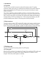
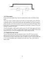
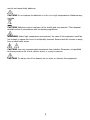
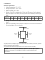
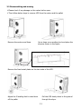
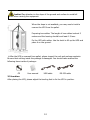
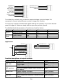
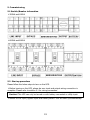
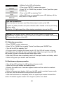
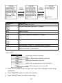
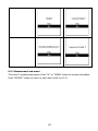
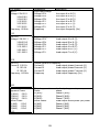
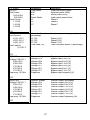
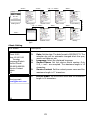
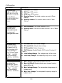
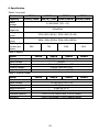
USER MANUAL 3/3 ON LINE UPS 30~80KVA Uninterruptible Power Supply Version: 1.1 Content 1. Introduction .................................................................................................... 1 1.1 Overview....................................................................................................... 1 1.2 Basic structure ............................................................................................... 1 1.3 Working mode ............................................................................................... 1 1.4 Overview....................................................................................................... 5 2. Important Safety Warning ............................................................................. 6 2.1 Conventions and used symbols........................................................................ 6 2.2 Safety instructions ......................................................................................... 7 3. Installation .................................................................................................... 10 3.1 Basic requirement ........................................................................................ 10 3.2 Disassembling and moving............................................................................ 11 3.3 Location ...................................................................................................... 12 4. Electrical connection ..................................................................................... 13 4.1 Power connection ........................................................................................ 13 4.2 Communication ............................................................................................ 15 5. Commissioning .............................................................................................. 19 5.1 Switch/Breaker information ........................................................................... 19 5.2 Start up procedure ....................................................................................... 19 5.3 Shutdown procedure .................................................................................... 20 5.4 Maintenance bypass operation ...................................................................... 20 6. Interface ....................................................................................................... 21 6.1 Control panel ............................................................................................... 21 6.2 LCD information ........................................................................................... 22 6.3 Sub-menus .................................................................................................. 24 7. Maintenance .................................................................................................. 38 7.1 System maintenance .................................................................................... 38 7.2 Battery maintenance .................................................................................... 38 8. Trouble shooting ........................................................................................... 39 8.1 Warning code .............................................................................................. 39 8.2 Fault code ................................................................................................... 39 9. Specification.................................................................................................. 41 1. Introduction 1.1 Overview This UPS series is a double conversion system with sinewave output. It supplies continuous, stable, clean power for commercial and industrial environments. When the utility is lost accidentally, the UPS system will use the power from battery to output without interruption. This system is applied an advanced digital controller to control the double conversion system, and with an isolated transformer at the output to protect the load and the UPS itself. The UPS is also built-in user-friendly LCD interface and multiple communications including Modbus, RS-232 and intelligent slot. With free download software, this UPS provides complete power solution of monitoring and controlling remotely. 1.2 Basic structure The whole system consists of REC module, INV module, static bypass, maintain bypass and battery controller. The output of the UPS are switched over to either line input or bypass input with two SCRs operated in parallel. The basic structure is shown as below: SW1 SCR2 Bypass input SW2 REC Module Line input SCR3 INV Module SW3 ISO TX SW4 Load output SCR1 Fuse Battery 1.3 Working mode This part will introduce the working mode of the UPS system. 1.3.1 Line mode When the UPS is working in line mode, the AC input will be rectified by REC module, and then be converted to the output via INV module. Meanwhile, the battery is being charged. At this time, static bypass is in standby. 1 Bypass input INV module REC module Line input Battery 1.3.2 Battery mode When the utility fails, the UPS will transfer to battery mode without interruption. The UPS converts the power from battery to output. At this time, static bypass is still in standby. If the utility is recovered, the UPS will transfer back to line mode again. Bypass input REC module INV module Line input Battery 1.3.3 Static bypass mode Bypass mode can be enabled or disabled by user setting. The default setting is enabled. The UPS system will work in bypass mode when the following conditions occur. The UPS system doesn’t turn on. The UPS is overload in line mode. The rectifier or inverter module is abnormal. The utility fails and the battery is discharged to low level. When above mentioned situation is eliminated, the UPS will transfer back to line mode or battery mode. 2 Bypass input REC module INV module Line input Battery 1.3.4 ECO MODE ECO mode can be enabled or disabled by user setting. The default setting is disabled. If it’s required to have high efficiency performance instead of the high power quality, it’s better to enable “ECO mode”. In this mode, load will be supported via Bypass input when utility quality is OK. And the Line input will still be operated to charge battery and INV module is in standby status with switch opened. When Bypass input is lost, the system will transfer to line mode or battery mode. When Bypass input is restored, the system transfers back to bypass mode again. This ECO mode operation greatly improves system efficiency. Bypass input REC module INV module Line input Battery 1.3.5 Maintain bypass mode When the UPS needs maintenance and load needs uninterruptible power, the users can firstly transfer the inverter to bypass mode, and then switch on maintain bypass breaker. After that, switch off all other breakers and switches. In this condition, the utility can still power the load and users can maintain the UPS. 3 Bypass input REC module INV module Line input Battery 1.3.6 Other modes Except mentioned modes above, there are standby mode, power-off mode and fault mode. There is no output in standby mode, but the utility will charge battery. If the UPS stays in standby mode for a while without utility and load connection, the UPS will transfer to power-off mode. At this time, the UPS can’t be turned on by pressing ON button. Please kindly wait for 5 minutes to allow UPS completely off itself. After 5 minutes, UPS can be restarted by pressing ON button. The UPS will transfer to fault mode if a fault occurs in the UPS. When some minor faults occur, the UPS still can transfer to bypass mode if bypass input is available. When some severe faults occur, it won’t be eliminated until the users restart the UPS. 1.3.7 Single/Dual input source The line input and bypass input are separated routes in this UPS. Users can apply different power sourced into these two input routes and set up a dual-input system. Users also can connect the same power source to these two inputs. Once the utility fails, no Line input and bypass input is available at the same time. Then, it will transfer to battery mode. 4 1.4 Overview Front view Back view of 30KVA/40KVA Back view of 60KVA/80KVA 1) Interface 2) Terminals 3) Breaker and switch 4) Fans 5) Communication 6) Cold start button 5 2. Important Safety Warning 2.1 Conventions and used symbols Conventions used: WARNING! Warnings identify conditions or practices that could result in personal injury; CAUTION! Caution identify conditions or practices that could result in damaged to the unit or other equipment connected. Warning, risk of electric shock Warning, risk of danger Warning, risk of electric shock, energy storage timed discharge Refer to the operating instructions Warning, danger of the possible fall down of the equipment Warning, Danger of fan’s rotation. Warning, hot surface Protective conductor terminal Earth (ground) terminal Direct current Alternating current Both direct and alternating current Three-phase alternating current Three-phase alternating current with neutral conductor Preservation of the environment: the users can contact with their provider or with the pertinent local authorities to be informed on how and where they can take the product to be recycled and/or disposed correctly. 6 2.2 Safety instructions WARNING! Before installing and using this equipment, read all instructions and cautionary markings on the UPS and this manual. Store the manual where it can be accessed easily. WARNING! This manual is for qualified personnel. The tasks described in this manual may be performed by qualified personnel only. WARNING! This equipment must be installed by qualified person. WARNING! An earth cable whose cross section should be the same as or greater than the power supply cable has to be connected to the protective earth connection. WARNING! Make sure the UPS is isolated and protective earth correctly connected at installing and before operating the UPS. CAUTION! This UPS should use for an IT distribution system. CAUTION! The UPS’s output neutral is same as the input neutral(Non isolate type). For the correct operation of the UPS, the input neutral cable should be connected. It may cause power loss without input neutral. CAUTION! Please transport the UPS with packaged from factory. WARNING! Pay attention to the slope of the ground and surface to avoid fall down when moving the equipment. CAUTION! Use the foot shore to support the USP but not the wheel. WARNING! This equipment is heavy. Do not lifte too heavy without help. 7 CAUTION! The UPS can only working on dry condition. Shut down the UPS if any liquid flows into the UPS and dry it with absorbent cloth. Please use dry cloth when clean the UPS. CAUTION! Please charge the battery first if using the UPS for first time or no using the UPS for a long period of time (6 months maximum). WARNING! Never manipulate the equipment with wet hands. CAUTION! To avoid a risk of fire and electric shock, make sure that existing wiring is in good condition and that the wire is not undersized. Do not operate the Inverter with damaged or substandard wiring. WARNING! When the UPS shut down the power supply to the load because of EPO signal trigger, the equipment has power supply yet. To shut down the equipment’s power, please turn off all the input power. WARNING! Authorized service personnel should reduce the risk of electrical shock by disconnecting both the AC and DC power from the UPS before attempting any maintenance or cleaning or working on any circuits connected to the inverter. Turning off controls will not reduce this risk. Internal capacitors can remain charged after disconnecting all sources of power. CAUTION! Do not open, disassemble or modify the equipment yourself. It contains no user-serviceable parts. Attempt to service this equipment yourself may cause a risk of electrical shock or fire and will void the warranty from the manufacturer. CAUTION! Shut down the UPS If any smoke or gas exhausts from the UPS. WARNING! Battery circuit is not isolated; it is dangerous to touch any part of the batteries. CAUTION! When batteries are replaced, the complete battery set has to be replaced 8 and do not reuse faulty batteries. CAUTION! Do not expose the batteries in a fire or to high temperatures. Batteries may explode. CAUTION! Batteries involve a serious risk for health and environment. Their disposal should be done in accordance with the existing regulations. WARNING! Under high temperature environment, the case of this equipment could be hot enough to cause skin burns if accidentally touched. Ensure that this inverter is away from normal traffic areas. CAUTION! Use only recommended accessories from installer. Otherwise, not-qualified tools may cause a risk of fire, electric shock, or injury to persons. CAUTION! To reduce risk of fire hazard, do not cover or obstruct the equipment. 9 3. Installation 3.1 Basic requirement Ambient temperature: 0°C~+55°C Storage temperature: -15ºC ~ 60ºC Relative humidity: 5% ~ 95% Altitude: If the UPS is installed within 1000m, the UPS power will not be derated. When the height is over 1000m, the output power will be derated by following the table. Altitude(m) 1000 1500 2000 2500 3000 3500 4000 4500 5000 Coefficient 100% 95% 91% 86% 82% 78% 74% 70% 67% Vertical: No vibration and the degree of deviation from vertical shouldn’t be more than 5°. Space: It’s requested to have a clearance of approx. 80 cm to the front and back of the unit and approx. 20 cm to the side. Minimum 80cm Minimum 20cm Minimum 20cm Minimum 80cm The UPS should be installed in the environment with free ventilation, less dust, optimum ambient temperature and humidity. The recommended ambient temperature is 20°C~25°C with 50% humidity. Caution! It’s NOT allow to have flammable, explosive or corrosive gas or liquid in installation environment. It is forbidden to install in a metal conductive dust environment. 10 3.2 Disassembling and moving Please check if any damage on the carton before open. Then follow below steps to remove UPS from the carton and the pallet. Remove the cartons and foam. Use a slope as an auxiliary tool and place the slope as shown in the figure. Remove the fixed metal plates on the two sides of the UPS. Adjust the 2 leveling feet to raise them Pull the UPS slowly down to the ground off the pallet. through the slope. 11 Caution! Pay attention to the slope of the ground and surface to avoid fall down when moving the equipment. When the slope is not available, you may need a hoist to remove the UPS from the pallet. Preparing two cables. The length of two cables is about 3 meters and the bearing should be at least 1.5 tons. Fix the UPS with cables. Use the hoist to lift up the UPS and place it on the ground. After the UPS is removed from pallet, please inspect the unit and package contents. Be sure that nothing inside the package is damaged. You should have received the following items inside of package: CD User manual USB cable RS-232 cable 3.3 Location After placing the UPS, please adjust the leveling feet to fix the UPS in position. 12 4. Electrical connection 4.1 Power connection Please follow the below figures to remove the terminal cover. All connected wires need to be inserted through the wire hole which is beneath the terminals. 60/80KVA 30/40KVA After removing the cover, the wire terminals of each model are shown as below: 30KVA/40KVA 60KVA/80KVA 13 The ground terminal is shown as below: The specifications of internal breaker, fuse and switch are shown as below: UPS Model Breaker LINE INPUT Fuse Switch BYPASS M-BYPASS BATTERY BATTERY BATTERY OUTPUT 30KVA 100A/3P 63A/3P 63A/3P 63A/2P N/A N/A 80A/3P 40KVA 125A/3P 100A/3P 100A/3P 63A/2P N/A N/A 80A/3P 60KVA 200A/3P 160A/3P 160A/3P N/A 350A 125A/3P 125A/3P 80KVA 250A/3P 200A/3P 200A/3P N/A 350A 125A/3P 125A/3P Caution! Please make sure that all switches and breakers are open before installation. The recommended sizes of the cables are listed as below: UPS Model Line Input and Ground Size BYPASS/OUTPUT BATTERY (AWG) Cross section (mm2) Size (AWG) Cross section (mm2) Size (AWG) Cross section (mm2) 30KVA ≤6 ≥ 10 ≤8 ≥8 ≤4 ≥ 20 40KVA ≤4 ≥ 16 ≤6 ≥ 14 ≤2 ≥ 30 60KVA ≤2 ≥ 25 ≤4 ≥ 22 ≤ 1/0 ≥ 50 80KVA ≤ 1/0 ≥ 40 ≤2 ≥ 38 ≤ 3/0 ≥ 80 14 The recommended sizes of the ring terminals are listed as below: Items D (mm) L (mm) Torque (Nm) 30K/40K AC INPUT/ BYPASS/ OUTPUT/BATTERY 8.4 16 4.5 60K/80K AC INPUT/ BYPASS/ OUTPUT 8.4 16 4.5 BATTERY 10.5 22 9 After connecting all the cables, please double check the issues as below: Check the phase sequence of LINE INPUT, BYPASS and OUTPUT. Check the polarity of the battery cables. Make sure all the connected cables are screwed tightly. 4.2 Communication The UPS provides a variety of communications. The details are listed as below: Intelligent slot Iutput Output Dry contact EPO 4.2.1 Intelligent slot The intelligent slot can provide SNMP solution for remote monitor. Please request the supplier for detail information. 4.2.2 Dry contact There are 6 output and 2 input dry contacts. The detailed functions are listed as below. 15 COMMON UPS fault UPS warning Low battery Line lost Bypass mode Inverter mode Preserved Remote turn on Remote turn off Ground The output dry contacts only provide two passive statuses: short and open. It’s necessary to connect external power source to trigger this function. The input dry contacts provide active signals and it’s not necessary to connect external power to trigger it. Users can simply short or open the ports to ground. The detailed electrical parameters of contacts are listed as below: Contacts Output Input Parameters Relay dc voltage Relay dc current Output voltage Output current Typical 12 0.5 N/A N/A Maximum 30 1 5 15 Unit V A V mA Application: +12V Remote turn on Remote turn off Common UPS fault UPS warning Battery low Ground Line lost Bypass mode Inverter mode Function descriptions of output contacts: Output contacts UPS fault UPS warning Battery low Line lost Description UPS works normally. UPS is fault. UPS works normally. UPS is in standby, bypass, fault, line loss or low battery. Battery voltage is normal. Battery voltage drops to low alarm point. Line voltage and frequency is under normal range. 16 Status Open (Default) Short Open (Default) Short Open (Default) Short Open (Default) Bypass mode Inverter mode Line voltage and frequency exceeds normal range. UPS isn’t in bypass mode. UPS is in bypass mode. UPS isn’t in line or battery mode. UPS is in line or battery mode. Short Open (Default) Short Open (Default) Short Function descriptions of input contacts: Input contacts Remote turn on Remote turn off Status Open (Default) Short Open (Default) Short Description No action Turn on No action Turn off 4.2.3 EPO Emergency Power Off (EPO) is the capability to shut down a system. It contains two pins of terminal strip. When it’s in open circuit, it will activate shutdown of the system and cut off output. When it’s in close status for UPS normal operation. 4.2.4 USB/RS232 To allow for unattended UPS shutdown/start-up and status monitoring, connect the bundled USB communication cable one end to the USB port and the other to the communication port of your PC. If using RS-232 communication, please use RS-232 cable to connect UPS and your PC. With the monitoring software installed, you can schedule UPS shutdown/start-up and monitor UPS status through PC. 4.2.5 RS485 Definition of RS485 pins : Pin# 4 5 8 Description RS485-B RS485-A GND 17 Single unit application : First, please use one RS485 to RS 232 converter or RS-485 to Modbus/TCP converter as media converter between RS485 and computer. Please follow below chart for wiring connection between RS485 and media converter: Then, follow below diagram to connect personal computer: Using RS-485 to RS-232 converter Use RS-485 to Modbus/TCP converter The maximum communication distance can be up to 1200m. Multiple monitoring application: The RS-485 can support 31 units in maximum for centralized monitoring. Please set the address of each unit in the LCD. Each unit should have unique address. Otherwise, it will cause conflicts in the line. 18 5. Commissioning 5.1 Switch/Breaker information 30KVA and 40KVA 60KVA and 80KVA 5.2 Start up procedure Please follow the below steps to turn on the UPS. Before turning on the UPS, please be sure input and output wiring connection is complete. Please refer to section 2.1 for wiring connection. Caution! This UPS can only be turned on with battery connected or utility input. Switch on line input, bypass input and battery switch. UPS will start up automatically. 19 Waiting for the UPS self-checking. Then, press “ENTER” to enter main menu. Press “UP” or “DOWN” key to select “Control”, and then press “ENTER” key. Turn on the UPS by selecting “Yes”. When UPS turns on successfully, green LED lights up. At this time, switch on output switch. Cold start procedures: When line input is lost, users can follow below steps to start up the UPS: Switch on battery breaker and press cold start button located on the top of cooling fan for a while. Wait for LCD lighting and then follow startup procedure to turn on the UPS. Caution! When bypass mode is enabled, the UPS will transfer to bypass mode automatically if bypass input is OK. The UPS won’t transfer to line mode until entering LCD main menu to turn on the UPS. 5.3 Shutdown procedure Press “ENTER” to enter main menu. Press “UP” or “DOWN” key to select “Control”, and then press “ENTER” key. Turn off the UPS by selecting “Yes”. If bypass mode is enabled and bypass input is OK, the UPS will transfer to bypass mode. Otherwise, the UPS will stay in standby mode. When line input is lost, the UPS will transfer to power off mode and shut down after a while. After the UPS shuts down completely, switch off line input breaker and battery switch. Switch off bypass input breaker and load switch. 5.4 Maintenance bypass operation Turn off the UPS and keep the UPS working in bypass mode. Switch off line input breaker and battery switch. Remove the metal cover of maintain bypass breaker and then switch on maintain bypass breaker. Switch off bypass input breaker. Until now, the UPS works in maintain bypass mode. At this time, the load should be working without interruption. After the maintenance is completed, switch on bypass input breaker first and then switch off maintain bypass breaker. Don’t forget to put the cover back. 20 6. Interface e od Fa u lt m od m tte ry Ba By Li pa ne ss m m od e od e e 6.1 Control panel TE R EN D O W N P U ES C LCD Display 6.1.1 LED indicators Mode Bypass Line Battery LED UPS start Standby O ● ● Bypass mode O ● ● Line mode ● O ● Battery mode ● ● O Fault ● ● ● Warning ● ● ● Battery test ● O O ECO mode O O ● Note: ● means LED is lit; O means LED is faded; means LED is flashing. Fault ● ● ● ● O ● ● 6.1.2 Buzzer UPS state Bypass/Standby Battery / Battery-test mode (normal battery voltage) Battery / Battery-test mode (low battery voltage) Fault Warnings (except overload) Overload Buzzer status Beeping once every 2 minutes Muted Yes Beeping once every 4 seconds Yes Beeping once every second Yes Beeping continuously Beeping once every second Beeping twice every second Yes No No 21 6.1.3 Button definition Button ON/ENTER OFF/ESC UP DOWN Function Description Turn on the UPS: Press and hold the button more than 0.5s to turn on the UPS. Enter setting menu: Press this button to enter setting menu. Enter Key: Press this button to confirm the selection in setting menu. Turn off the UPS: Press and hold the button more than 0.5s to turn off the UPS. Esc key: Press this button to exit from setting menu or cancel the setting. Press this button to select the upper item in the menu or previous page in the screen or increase the number in the setting. Press this button to select the lower item in the menu or next page in the screen or decrease the number in the setting. 6.2 LCD information 6.2.1 Basic Press “ENTER” Waiting Press “ESC” Initializing Home Page Main menu After the UPS is powered on, LCD will initialize first and then display main page. After pressing “ENTER” button, it will enter main menu. Initialization When first starting up the UPS, the LCD will show initialization. Please kindly wait. Main page This page is used to display basic information. Users can get the UPS information by pressing “UP” and “DOWN” buttons. 22 Parameters MODE OP1N OP2N OP3N BATV Total Load IP1N IP2N IP3N BY1N BY2N BY3N TYPE Event show… Press “DOWN” Press “DOWN” Press “UP” Press “UP” Description Working mode of the UPS Output voltage and frequency in 3-phase Battery voltage The total connected loads in percentage Line input voltage and frequency in 3-phase Bypass voltage and frequency in 3-phase Working type: “Single” or “Parallel& parallel numbers” Show current events such as turn on, warning, fault etc. If there is no event, it will be blank. Main menu Control: Main functions command Measure: Show detail information of the UPS Setting: Set parameters of the UPS Alarm: Show current warning or fault information Record: Recording the events of the UPS 1) Press “UP” or “DOWN” button to select sub-menus. When selected, the text will be highlighted. 2) Press “ON/ENTER” button to confirm the selection. 3) Press “OFF/ESC” button to return to main page. 23 6.3 Sub-menus 6.3.1 Control sub-menu There are 4 options listed in Control sub-menu: Turn on, Batt Test (Battery test), Mute, S.D &R (Shutdown and restore). It is to real-time control the UPS. Press “UP” or “DOWN” button to switch selection. Press “ON/ENTER” button to confirm the selection. Then, press “OFF/ESC” button to return to main menu (refer to 6-2-1). 1) Turn On: “Turn On” will be displayed if UPS is not turned on. Otherwise, “Turn off” will be displayed. 2) Batt Tes: “Batt test” will be displayed if UPS is not in battery test mode. Otherwise, “Cancel Batt Test” will be displayed. 3) Mute: “Mute” will be displayed if UPS is not in mute status. Otherwise, “Cancel Mute” will be displayed. 4) S.D&R: “S.D & R” will be displayed if UPS is not in the shutdown and restore process. Otherwise, “Cancel S.D & R” will be displayed. CONTROL Turn On Bat. Test Mute S.D&R CONTROL Sub-Menu 24 6.3.2 Measurement sub-menu There are 10 measurement pages. Press “UP” or “DOWN” button to browse information. Press “OFF/ESC” button to return to main menu (refer to 6-2-1). 25 LCD Screen INPUT Voltage V1N:221.1 V2N:219.5 V3N:219.5 V12:383.2 V23:383.2 V31:383.2 Frequency :50.0Hz Parameters Line input voltage Voltage V1N Voltage V2N Voltage V3N Voltage V12 Voltage V23 Voltage V31 Frequency 1/10 OUTPUT Voltage V1N:221.1 V2N:219.5 V3N:219.5 V12:383.2 V23:383.2 V31:383.2 Output voltage Voltage V1N Voltage V2N Voltage V3N Voltage V12 Voltage V23 Voltage V31 Description Line Line Line Line Line Line Line input input input input input input input Load Load Load Load Load Load A to N (V) B to N (V) C to N (V) A to B (V) B to C (V) C to A (V) frequency (Hz) output output output output output output A to B to C to A to B to C to N (V) N (V) N (V) B (V) C (V) A (V) 2/10 OUTPUT Current I1 :100.1A I2 :100.1A I3 :100.1A Frequency :50.0Hz Output current & frequency Current I1 Load output phase A current (A) Current I2 Load output phase B current (A) Current I3 Load output phase C current (A) Frequency Load output frequency (Hz) 3/10 OUTPUT Apparent Power L1(KVA) :130.0 L3(KVA) :130.0 L3(KVA) :130.0 Active Power L1(KW) :120.0 L2(KW) :120.0 L3(KW) :120.0 4/10 Output apparent Power L1(KVA) L2(KVA) L3(KVA) Active Power L1(KW) L2(KW) L3(KW) 26 Load output apparent power per phase Phase A (KVA) Phase B (KVA) Phase C (KVA) Load output active power per phase Phase A (KW) Phase B (KW) Phase C (KW) LCD Screen OUTPUT Total Power KVA:300.0 KW:240.0 Power Factor L1:0.80 L2:0.80 L3:0.80 Parameters Total Power KVA KW Power Factor L1 L2 L3 Description Load total output power Apparent power (KVA) Active power (KVA) Load output power factor Phase A Phase B Phase C 5/10 OUTPUT Load Percent L1(%):101.2 L2(%):101.2 L3(%):101.2 Total Load(%) (%):101.2 Connected Load in percentage L1 (%) L2 (%) L3 (%) Total Load (%) Load power percentage per phase 6/10 BYPASS Voltage V1N:221.1 V2N:219.5 V2N:219.5 V12:383.2 V23:383.2 V31:383.2 Frequcncy :50.0Hz Bypass voltage Voltage V1N Voltage V2N Voltage V3N Voltage V12 Voltage V23 Voltage V31 Frequency Bypass Bypass Bypass Bypass Bypass Bypass Bypass Bypass 7/10 INVERTER Voltage V1N:221.1 V2N:219.5 V2N:219.5 V12:383.2 V23:383.2 V31:383.2 Frequcncy :50.0Hz Inverter voltage Voltage V1N Voltage V2N Voltage V3N Voltage V12 Voltage V23 Voltage V31 Frequency Inverter Inverter Inverter Inverter Inverter Inverter Inverter Inverter 8/10 27 Phase A (%) Phase B (%) Phase C (%) Total connected power in percentage input input input input input input input input information A to N (V) B to N (V) C to N (V) A to B (V) B to C (V) C to A (V) frequency (V) output output output output output output output output information A to N (V) B to N (V) C to N (V) A to B (V) B to C (V) C to A (V) frequency (Hz) LCD Screen BATTERY&CHARGER Battery Voltage 422.4V DC Bus Voltage 422.4V Charging Current 5.2 A Discharging current 5.2 A 9/10 TEMPERATURE Control: 137 Battery: 137 REC : 137 INV0 : 137 INV1 : 137 SCR : 137 Parameters Description Battery and charger information Battery Voltage Battery Voltage (V) DC Bus Voltage DC Bus Voltage (V) Charging current Charging current (A) Discharging current Discharging current (A) Temperature information Control Control board temperature (°C) Battery Battery SCR temperature (°C) REC Rectify SCR temperature (°C) INV0 INV0 IGBT temperature (°C) INV1 INV1 IGBT temperature (°C) SCR Output SCR temperature (°C) 10/10 6.3.3 Setting sub-menu This sub-menu is used to set the parameters of UPS and show the current setting information. There are 3 options: Basic, Information and Advanced. Press “UP” or “DOWN” button to switch selection. Press “ON/ENTER” button to confirm the selection. Then, press “OFF/ESC” button to return to main menu (refer to 6-2-1). NOTE: Not all settings could be available in every operation mode. If the setting is not available in present mode, the LCD will keep its original setting parameter showed instead of changing the parameters. Please follow the steps as below to operate this sub-menu. 28 “Enter” Setting page “Up”or“Down” Enable cursor “Up”or“Down” Move cursor “ESC” “Enter” Cursor flicking “Enter” “Up”or“Down” Setting menu “Enter” “ESC” PgUp or pgDn Disable cursor Confirm Modify Basic Setting LCD Screen BASIC SETTING Clock:16:25 Date :2014/11/06 Tuesday Language:English Service Phone: 000-0000-000000 Service Contact: Admin 1/4 BASIC SETTING Service email: [email protected] Description 1. 2. 3. 4. Clock: Set the time. The time format is HH:MM:SS. Date: Set the date. The date format is MM/DD/YYYY. The calendar day will be automatic changed when the year, month and date are set. Language: Select the displayed language. Service Phone: Set the service phone number. Only 0~9, + and – are accepted. The maximum length is 14 characters. 5. Service Contact: Set the contact person name and the maximum length is 17 characters. 1. Service Email: Set the service email and the maximum length is 34 characters. 2/4 29 LCD Screen BASIC SETTING RS485 Baud Rate: 19200 RS485 Protocol: Modbus Modbus Address:1 Description 1. RS485 Baud Rate: Select RS485 baud rate. The default setting of baud rate is 19200. 2. RS485 Protocol: Select the RS485 protocol type. The default setting of protocol type is “Modbus”. 3. Modbus Address: Set the Modbus address. The range is from 1 to 255. 3/4 BASIC SETTING Auto Bat.Test:Dis Type :Monthly Weekday :Mon Hour&Min :11:42 Day of month: 21 Permanently mute Mode:Dis Warn:Dis All:Dis Faul:Dis 4/4 1. Automatic battery test: You can choose enable/disable the auto battery test function. If “Enable” is selected, please also set up other parameters. Type: Select automatic battery test type. There are three options: Monthly, weekly and daily. And all detailed testing frequency such as time and date can be set up next. 2. Permanently mute: There are four events available to mute. You may choose “Enable” or “Disable” alarm when related events occur. En: Enable. When selected, alarm will be mute when related events occur. Dis: Disable. When selected, UPS will alarm when related events occur. Mode: Enable/Disable this function. Warning: When “enable” is selected, only warning events will be mute. All: When “enable” is selected, all the faults and warnings events will be mute. Fault: When “enable” is selected, only fault events will be mute. 30 Information LCD Screen Description INFORMATION LCD Ver.: 0372-02 DSP Ver.: Ver.4.4 D MCU Ver.: Ver.4.4 D Service Phone: 000-0000-00000000 Service Contact: Admin 1. LCD Ver.: LCD version. 2. DSP Ver.: DSP version. 3. MCU Ver.: MCU version. 4. Service Phone: The listed numbers are set in “Basic Setting”. 5. Service Contact: The contact name is set in “Basic Setting”. 1/7 INFORMATION Serial Number: 92931403100025 Service email: [email protected] 1. Serial Number: The serial number of UPS. 2. Service email: The service email account is set in “Basic Setting”. 2/7 INFORMATION IP rated Volt:230 OP rated Volt:230 OP Freq.(Hz) :50.0 CVCF status:Dis Line Voltage Range: L:176V H:265V Line Freq.Range: L:46.0Hz H:54.0Hz 3/7 1. IP rated Volt: Input rated voltage. INFORMATION Byp.forbid:Yes Byp.at UPS off:DIS Byp. Voltage Range: L:176V H:265V Byp. Freq.Range: L:46.0Hz H:54.0Hz 1. Byp. forbid: Enable/disable bypass function. 2. OP rated Volt: Output rated voltage. 3. OP Freq.(Hz): Output frequency. 4. CVCF status: Enable/Disable CVCF mode (Constant V and F). 5. Line Voltage Range: The voltage range of line input. 6. Line Freq. Range: The frequency range of line input. 2. Byp. At UPS off: Enable/disable auto bypass function when UPS is off. 3. Byp. Voltage Range: The acceptable voltage range for bypass input. 4. Byp. Freq. Range: The acceptable frequency range for bypass input. 4/7 31 LCD Screen Description INFORMATION ECO Status:Dis ECO Voltage Range: L:205V H:235V ECO Freq.Range : L:48.0Hz H:52.0Hz 1. ECO Status: Enable/disable ECO function. 2. ECO Voltage Range: The acceptable voltage range for ECO mode. 3. ECO Freq. Range: The acceptable frequency range for ECO mode. 4. Auto-Restart: Enable/disable auto-restart function. Auto-Restart:Dis 5/7 INFORMATION Bat.Mode Work Time: 9999Min Bat.Warn Volt L:10.5V H:14.5V S.D Volt: 10.5V 1. Bat. Mode Work Time: The maximum discharge time in battery mode. 2. Bat Warn Volt: L: Low battery warning voltage. H: High battery cut-off voltage. 3. Battery shutdown voltage: The battery shutdown voltage. 6/7 INFORMATION Sys. Shutdown Time Min:4 Sys. Restore Time Min:4 1. Sys. Shutdown Time: The system shutdown time. 2. Sys. Restore Time: The system restore time. 7/7 32 Advanced LCD Screen USER Password: Description It’s required to enter password (4 digits) to access the “ADVANCED”. The default password is “0000”. If entered password is right, the page will jump to setting screen. If the password is wrong, it will ask to enter again. 0000 USER OP rated Volt:220 OP Freq.(Hz) :50.0 CVCF status:Dis Line Voltage Range: L:176V H:265V Line Freq.Range: L:46Hz H:54Hz 1/5 1. OP rated voltage: Select the output rated voltage. There are three options, 220Vac, 230Vac and 240Vac. 220Vac is default setting. 2. OP Frequency: Select the output frequency 50Hz: The output frequency is setting for 50Hz. 60Hz: The output frequency is setting for 60Hz. 50Hz is default setting. 3. CVCF status (constant voltage and constant frequency function) En : CVCF function is enabled. The output frequency will be fixed at 50Hz or 60Hz according to setting of “OP Freq.”. The input frequency could be from 40Hz to 70Hz. Dis: CVCF function is disabled. The output frequency will synchronize with the bypass frequency within 45~55 Hz for 50Hz system or within 55~65 Hz for 60Hz system. Disable is the default setting. 4. Line Voltage range: Set the acceptable line input voltage range. L: Low voltage point for line voltage. The setting range is 176V ~ 205V. 176V is default setting. H: High voltage point for line voltage. The setting range is 235V ~ 265V. 265V is default setting. 5. Line Frequency range: Set the acceptable line input frequency range. L: Low frequency point for line voltage. The setting range is 45Hz ~ 49Hz for 50Hz system and 55Hz ~ 59Hz for 60Hz system. 46Hz is default setting for 50Hz system and 56Hz is default setting for 60Hz system. H: High frequency point for line voltage. The setting range is 51Hz ~ 56Hz for 50Hz system and 61Hz ~ 66Hz for 60Hz system. 54Hz is default setting for 50Hz system and 64Hz is default setting for 60Hz system. 33 LCD Screen USER Byp.forbid:No Byp.at UPS off: En Byp. Voltage Range: L:176V H:265V Byp. Freq.Range : L:46Hz H:54Hz 2/5 Description 1. Bypass forbidden: No: Bypass allowed. When selected, UPS will run at Bypass mode depending on “Byp.at off” setting. It is the default setting. Yes: Bypass not allowed. When selected, it’s not allowed for running in Bypass mode under any situations. 2. Bypass at off: Select the bypass status when manually turning off the UPS. This setting is only available when “Bypass forbid.” is set to “No”. En: Bypass enabled. When selected, bypass mode is activated. DIS: Bypass disabled. When selected, no output through bypass when manually turning off the UPS. 3. Bypass voltage range: Set the bypass voltage range. L: Low voltage point for bypass. The setting range is 176V ~ 205V. 176V is default setting. H: High voltage point for bypass. The setting range is 235V ~ 265V. 265V is default setting. 4. Bypass frequency range: Set the bypass frequency range. L: Low frequency point for bypass. The setting range is 45Hz ~ 49Hz for 50Hz system and 55Hz ~ 59Hz for 60Hz system. 46Hz is default setting for 50Hz system and 56Hz is default setting for 60Hz system. H: High frequency point for bypass. The setting range is 51Hz ~ 56Hz for 50Hz system and 61Hz ~ 66Hz for 60Hz system. 54Hz is default setting for 50Hz system and 64Hz is default setting for 60Hz system. 34 LCD Screen Description USER ECO Status:Dis ECO Voltage Range: L:205V H:235V ECO Freq.Range : L:48Hz H:52Hz 1. ECO Status: Enable/Disable ECO mode. Default setting is “Disable”. Auto-Restart: En 3. ECO Freq. Range: Set the ECO frequency range. 3/5 2. ECO Voltage Range: Set the ECO voltage range. L: Low voltage point for ECO mode. The setting range is 176V ~ 210V. The default setting is 205V. H: High voltage point for ECO mode. The setting range is 230V ~ 265V. The default setting is 235V. L: Low frequency point for ECO mode. The setting range is s 45Hz ~ 49Hz for 50Hz system and 55Hz ~ 59Hz for 60Hz system. The default setting is 48Hz for 50Hz system and 58Hz for 60Hz system. H: High frequency point for ECO mode. The setting range is 51Hz ~ 56Hz for 50Hz system and 61Hz ~ 66Hz for 60Hz system. The default setting is 58Hz for 50Hz system and 62Hz for 60Hz system. 4. Auto-Restart: Enable/Disable auto-restart function. En: Enable the auto-restart function. If selected, once UPS shutdown occurs due to running out battery and then utility restores, the UPS will return to line mode. The default setting is “enable”. Dis: Disable the auto-restart function. If selected, once UPS shutdown occurs due to running out battery and then utility restores, the UPS will not restart. USER Bat.Mode Work Time(Min): 9999 Bat.Warn Volt L:10.5V H:14.5V S.D Volt: 10.5V 1. Bat. Mode Work Time(Min.): Set the maximum discharge time in battery mode. The setting range is from 1 to 999. The unit is minute. 2. Bat Warn Volt: L: Low battery warning voltage. The setting range is 11.2V ~ 12V. The default setting value is 11.2V. H: High battery cut-off voltage. The setting range is 13.5 V ~ 14.5 V. 4/5 3. Battery shutdown voltage: Set the battery shutdown voltage. When the battery voltage is lower than shutdown voltage in battery mode, the UPS will shut down. The setting range is from 10.5V to 11.3V. The default setting value is 10.5V. 35 USER Sys. S.D Time 1 s Sys. Restore Time 1 min New Password: NO 5/5 Fig. (1) USER Old Password: 0000 New Password: 0000 These two parameters are related to the “S.D & R” on the “CONTROL” sub-menu. If executing “S.D & R” action, the UPS will shut down and restore according to system shutdown time and system restore time setting here. For example, if the system shutdown time is 1 second, the system restore time is 2min, it means the UPS will shut down in 1 minute and wait for 2 minutes, then restart again. 1. System shutdown Time: Set the system shutdown time. The setting range is 1 sec. ~ 9999 sec. The default setting value is 1 second. 2. System Restore Time: Set the system restart time after shutdown. The setting range is 1 minute to 9999 minutes. The default setting value is 1 minute. 3. New Password: Modify password function. No: No change for password. YES: Modify the password. If selected, the LCD will display the screen as shown in Fig. (2). Fig. (2) 6.3.4 Alarm sub-menu LCD Screen Description ALARM W01 BATT. Open F02 BUS High ALARM page is used to display the current warning and fault information of the UPS. If no alarm occurs, it’s blank. W means warning. Warning code and short descriptions of warning event will display. Please refer section 8.1 for the warning code. F means fault. Fault code and short descriptions of fault event will be displayed. Please refer section 8.2 for the fault code. Press “ESC” button to go back to main menu. 36 6.3.5 Data log sub-menu LCD Screen Description DATA LOG Code:W01 Bus start fail Time: 09:27 2014/11/06 1) Data log is used for recording the warning and fault information of the UPS. The record contains code, basic information and time; No more date! 2) Press “ON” and “DOWN” to page up or down if the log has more than one page; 3) Press “ESC” button to go back main menu. “ENTER” button has no use in this page; 4) W + num.: Warning + Warning code; F + num.: Fault + Fault code, please refer to part 8 to have the detail information about warning and fault. 37 7. Maintenance Caution! Inside maintenance is only available for the engineer with qualified electrical knowledge. There is still possible high voltage inside of the unit even disconnect all connections. 7.1 System maintenance Check if indicators and LCD function well and the buttons are functional. Make sure there is no abnormal noise inside of the unit. Make sure nothing blocks the ventilation of the unit. Please use dry towel to clean the surface of the unit when it is not working. Please check the outlook condition of all wires and connection situation periodically after disconnecting all power. The checking interval should be less than 2 years. 7.2 Battery maintenance In order to prolong the lifecycle of the battery, please do the maintenance periodically. The lifecycle of the battery is based on ambient temperature and recharge cycles. Please make the battery working under the ambient temperature between 15°C ~25°C. Check the voltage of the battery pack weekly. Check the voltage of each battery monthly. Keep the environment of battery clean and tidy. Check the terminals of the batteries termly, make sure they are tightened. Please charge the battery once a month if the battery hasn’t been used for a long time. If the discharging time is much less than normal situation, please check if it’s time to replace them. 38 8. Trouble shooting 8.1 Warning code Code Event 01 Battery open 04 05 Line phase error Bypass phase error 07 Charging over voltage 08 Battery under 09 Overload 0B EPO open 0D Over temperature 33 Overload 3 times in half an hour 3A Maintain bypass enable How to do Please check if battery wires are connected correctly and battery switch is on. Please check the phase sequence of line input. Please check the phase sequence of bypass Check the battery voltage and then restart the unit. Remove all connected loads and charge the battery from utility. Remove some excessive loads based on UPS capacity. Please refer to 4.2.3. Remove some excessive loads and check the ventilation. Restart the UPS or the UPS keeps working in bypass mode. Don’t switch on maintain bypass breaker if it’s not for repair. 8.2 Fault code Code 01 02 03 11 12 13 14 15 16 17 18 19 Event BUS soft start fail BUS voltage high BUS voltage low INV soft start fail INV voltage high INV voltage low Output phase A short Output phase B short Output phase C short Output phase A short Output phase B short Output phase C short 24 SCR short 41 Over temperature How to do Restarts the unit. If the problem remains, please call for service. to to to to to to N N N phase B phase C phase A Disconnect the load first. Then restart the unit. If the unit is normal, please check the load. Restart the unit. If the problem remains, please call for service. Shut down the unit. Do NOT restart it until it’s cool down. 39 42 Communication fail 43 Overload Restart the unit. If the problem remains, please call for service. Remove some excessive loads based on UPS capacity. 40 9. Specification Table1: Line input Model Capacity Rated voltage Rated frequency Voltage range Frequency range Rated input current /per phase 30KVA 30KVA/24KW 40KVA 40KVA/32KW 60KVA 60KVA/48KW 80KVA 80KVA/64KW 3 x 380/400V (3Ph + N) 50Hz/60Hz 176V~265V (Ph-N) / 305V~460V (Ph-Ph) 46Hz~54Hz @50Hz; 56Hz~64Hz @60Hz 56A 73A 106A 140A Table 2: Battery Model Battery numbers Rated voltage Charging current Floating voltage High cut off point 30KVA 40KVA 60KVA 29/30/31/32 PCS (12V in series) 384VDC Default 10A; Maximum 40A 13.5VDC /per unit (12V) 14.5VDC / per unit (12V) 80KVA Table 3: Inverter output Model Waveform Rated voltage Tolerance Rated frequency THDV Overload capacity Efficiency 30KVA 40KVA 60KVA 80KVA Sinusoidal wave 3 x 380/400V (3Ph + N) ± 1% (Balanced) 50/60 Hz ± 1 % R load<1%; RCD load<3% 110%~150% 10min~60s; >160% 200ms >90% (Line mode); >95% (Battery mode) 41 Table 4: Bypass Model Rated voltage Rated frequency Voltage range Frequency range Transfer time Overload capacity 30KVA 40KVA 60KVA 80KVA 3 x 380/400V (3Ph + N) 50Hz/60Hz 176V~265V (Ph-N) / 305V~460V (Ph-Ph) 46Hz~54Hz @50Hz; 56Hz~64Hz @60Hz Synchronization: 0ms 150% ~ 180% 1h~30s; 180% ~ >200% 30s~200ms Table 5: Environment Model Working temperature range Storage temperature range Altitude Humidity IP degree Cooling Communication 30KVA 40KVA 60KVA 80KVA 0°C ~ 55°C -15ºC ~ 60ºC 0 ~ 1000m (Please refer to part 3.1 when over 1000m) 5% ~ 95% no condensing IP21 Forced air cooling RS232, USB, RS485, intelligent slot Table 6: Mechanics Model Depth (mm) Width (mm) Height (mm) Weight (kg) 30KVA 40KVA 60KVA 847.5 432.4 1134.5 271.5 1054 508 1287 298 42 80KVA 462 532