1
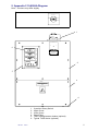
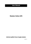
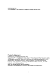
WBS HARDWIRED SERIES
4-60KVA
MAINTENANCE BYPASS SWITCH
Man 440
Issue 7
1
1. INTRODUCTION ........................................................................................................................ 3
2. INSTALLATION .......................................................................................................................... 3
2.1 Connection of the Mains Supply............................................................................................ 3
2.2 Connection of the Input to the UPS....................................................................................... 4
2.3 Connection of the Output from the UPS ................................................................................ 4
2.4 Connection of the Protected Equipment................................................................................ 4
2.5 Connection of the Auxiliary Contacts (optional)..................................................................... 4
2.6 Initial switch on ..................................................................................................................... 4
3. MAINTENANCE BYPASS SWITCH OPERATION...................................................................... 5
3.1 Switching to Bypass Operation (for UPS maintenance and testing only)............................... 5
3.2 Switching to Bypass Operation (for UPS maintenance and complete isolation only) ............. 5
3.3 Disconnection of the UPS ..................................................................................................... 5
3.4 Reconnection of the UPS...................................................................................................... 6
3.5 Switching back to Normal Operation ..................................................................................... 6
4. Transient Voltage Surge Suppressor or TVSS (Optional). .......................................................... 6
4.1 TVSS Operation.................................................................................................................... 6
4.2 TVSS Access........................................................................................................................ 6
4. Appendix 1 4-10kVA Diagram..................................................................................................... 7
5. Appendix 2 10-60kVA Diagram................................................................................................... 8
Man 440
Issue 7
2
1. INTRODUCTION
The Maintenance Bypass Switch (WBS) is a wall-mounted unit specially designed to allow
maintenance and removal of the UPS without any disruption of the supply to the protected
equipment (i.e. the load). It is fitted with a three-position switch that can be locked in 2 positions
only (NORMAL and BYPASS), thus preventing accidental switching during normal and bypass
operation. When the WBS is switched to the “NORMAL” position, backup is available from the
UPS in the event of a mains supply failure. In the “BYPASS & UPS” position, no backup is
available, but mains supply remains connected to the UPS. Finally when the WBS is switched to
the “BYPASS” position, no backup is available and the mains supply is disconnected from the
UPS. The “T” versions have additional transient voltage surge suppressor (TVSS) devices fitted.
WARNING!
The WBS should only be installed and operated by
authorised and trained personnel
2. INSTALLATION
WARNING: - The following procedure must be followed exactly. Failure to do so, could lead to
exposure to hazardous voltages and disruption of the supply to the protected equipment. It is
recommended that the following procedure be only carried out by a qualified electrician. THIS
EQUIPMENT MUST BE EARTHED.
Before commencing the installation ensure that the WBS is suitable for the UPS system for which it
is to be used, the connection cable sizes can be found in the UPS user manual. Remove the gland
plate, blanking grommets (if fitted) and front panel (panels) from the WBS, all plates and panels are
secured by several retaining screws and are connected to the unit via an earth connection, this
earth connection may be removed temporarily during the installation (the removable gland plate
must be drilled to suit your particular gland requirements). Mount the WBS securely to an even
surface (e.g. wall); this can be achieved using the four mounting holes located in the rear of the
enclosure. Once the WBS is securely mounted the connections can be made as described in the
next section: WARNING!
Hazardous voltages will be present on the terminal blocks if the UPS or mains supply is switched
on. Always ensure that the UPS and mains supply is switched off and isolated before proceeding.
(Refer to UPS operation manual for correct indications).
2.1 Connection of the Mains Supply
Feed the mains supply cables through the gland plate and secure, terminate the mains supply
cables to the terminals marked “SUPPLY IN” as follows: For Single Phase Input Supply
Wire
Terminal
Live (Brown)
Terminal Marked L
Neutral (Blue)
Terminal Marked N
Earth (Gn/Yw)
Terminal Marked E
For Three Phase Input Supply
Wire
Terminal
Phase 1 (Red)
- Terminal Marked L1
Phase 2 (Yellow)
- Terminal Marked L2
Phase 3 (Blue)
- Terminal Marked L3
Neutral (Black)
Terminal Marked N
Earth (Gn/Yw)
Terminal Marked E
Ensure that all terminals and glands are tight.
Man 440
Issue 7
3
2.2 Connection of the Input to the UPS
Feed the UPS input cables through the gland plate and secure, terminate the UPS input cables to
the terminals marked “UPS IN” as follows: For Single Phase Input
Wire
Terminal
Live (Brown)
Terminal Marked L
Neutral (Blue)
Terminal Marked N
Earth (Gn/Yw)
Terminal Marked E
For Three Phase Input
Wire
Terminal
Phase 1 (Red)
- Terminal Marked L1
Phase 2 (Yellow)
- Terminal Marked L2
Phase 3 (Blue)
- Terminal Marked L3
Neutral (Black)
Terminal Marked N
Earth (Gn/Yw)
Terminal Marked E
Ensure that all terminals and glands are tight.
2.3 Connection of the Output from the UPS
Feed the UPS output cables through the gland plate and secure, terminate the UPS output cables
to the terminals marked “UPS OUT” as follows: For Single Phase Output
Wire
Terminal
Live (Brown)
Terminal Marked L
Neutral (Blue)
Terminal Marked N
For Three Phase Output
Wire
Terminal
Phase 1 (Red)
- Terminal Marked L1
Phase 2 (Yellow)
- Terminal Marked L2
Phase 3 (Blue)
- Terminal Marked L3
Neutral (Black)
Terminal Marked N
Ensure that all terminals and glands are tight.
2.4 Connection of the Protected Equipment
Feed the protected equipment cables through the gland plate and secure, terminate the protected
equipment cables to the terminals marked “SUPPLY TO LOAD” as follows: For Single Phase Load
Wire
Terminal
Live (Brown)
Terminal Marked L
Neutral (Blue)
Terminal Marked N
Earth (Gn/Yw)
Terminal Marked E
For Three Phase Load
Wire
Terminal
Phase 1 (Red)
- Terminal Marked L1
Phase 2 (Yellow)
- Terminal Marked L2
Phase 3 (Blue)
- Terminal Marked L3
Neutral (Black)
Terminal Marked N
Earth (Gn/Yw)
Terminal Marked E
Ensure that all terminals and glands are tight.
2.5 Connection of the Auxiliary Contacts (optional)
The auxiliary contacts are only to be used if required, they allow the position of the bypass switch
to be monitored as follows: Switch Position
Volt free Contact Status
Normal
Open
Bypass & UPS
Closed
Bypass
Closed
Contact Rating - 20A @230Vac
2.6 Initial switch on
Before the mains supply is applied to the WBS: ♦ Refit all of the covers that were removed during installation, not forgetting the earth
connections.
♦ With the bypass switch in the normal position, switch on the supply.
♦ Start the UPS and confirm that the UPS operates correctly as described in its User Manual.
♦ Confirm that the TVSS device (if fitted) is operating correctly as described in it’s User
Manual.
♦ The unit is now installed.
Man 440
Issue 7
4
3. MAINTENANCE BYPASS SWITCH OPERATION
WARNING!
Always allow a 20 second break between switching positions
3.1 Switching to Bypass Operation (for UPS maintenance and testing only)
NOTE: - Check that the UPS is working normally and that it is not working in battery operation
mode (refer to UPS user manual).
If these conditions are not met, disruption or even damage can occur to the UPS or protected load
if the switch is operated.
♦ Turn the switch to the “BYPASS & UPS” position (central).
♦ The load is now supplied directly from the mains supply and the UPS still has input supply
connected.
♦ The UPS may now be switched off or tested (refer to UPS user manual) without disrupting
the load.
3.2 Switching to Bypass Operation (for UPS maintenance and complete isolation
only)
NOTE: - Check that the UPS is working normally and that it is not working in battery operation
mode (refer to UPS user manual).
If these conditions are not met, disruption or even damage can occur to the UPS or protected load
if the switch is operated.
♦ Turn the switch to the “BYPASS & UPS” position (central).
♦ The load is now supplied directly from the mains supply and the UPS still has input supply
connected.
♦ The UPS may now be switched off (refer to UPS user manual) without disrupting the load.
♦ Turn the switch to the “BYPASS” position (fully clockwise).
♦ The load will be continually supplied from the mains supply and the input supply to the UPS
will now be disconnected.
♦ The UPS may now be maintained without disrupting the load (always check the terminals
using a meter prior to touching).
3.3 Disconnection of the UPS
WARNING!
Hazardous voltages are always present within the WBS, unless completely
Isolated from the UPS and Mains Supply.
NOTE: - Check that the UPS is working normally and that it is not working in battery operation
mode (refer to UPS user manual)
If these conditions are not met, disruption or even damage can occur to the UPS or protected load
if the switch is operated.
♦ Turn the switch to the “BYPASS & UPS” (central) position.
♦ The load is now supplied directly from the mains supply and the UPS still has input supply
connected.
♦ Switch the UPS off completely following the UPS User Manual (ensuring the batteries are
also isolated).
♦ Turn the switch to the “BYPASS” (fully clockwise) position.
♦ The load is still supplied directly from the mains supply but the mains supply to the UPS is
now disconnected.
♦ WARNING: - Hazardous voltages are always present within the WBS, unless completely
isolated from the UPS and Mains Supply.
♦ Lock the switch in position if necessary.
♦ Remove the cover from the WBS.
♦ Using a meter, confirm that no voltage is present.
♦ Disconnect the cables from the terminals marked UPS IN and UPS OUT.
Man 440
Issue 7
5
♦ Disconnect the cables connected to the UPS input/output terminals.
♦ The UPS can now be removed for maintenance. The load will continue to be supplied
through the WBS.
♦ Replace all of the covers of the WBS and UPS.
3.4 Reconnection of the UPS
WARNING!
Hazardous voltages are always present within the WBS, unless completely
isolated from the UPS and Mains Supply.
♦ Reconnect the UPS, following section 2 (2.2 & 2.3) found earlier within this manual.
♦ Once all connections have been made replace all covers and refer to section 3.5.
3.5 Switching back to Normal Operation
WARNING!
Always allow a 20 second break between switching positions
♦ Turn the switch to the “BYPASS & UPS” (central) position.
♦ The UPS now has input supply available, whilst the load is still supplied directly from the
mains supply.
♦ Switch on the UPS ensuring correct operation (refer to UPS user manual).
♦ Check that the UPS is working normally and that it is not working in battery operation mode
(refer to UPS user manual). If these conditions are not met, disruption or even damage can
occur to the UPS or protected load if the switch is operated.
♦ Turn the bypass switch to the “NORMAL” (fully anti-clockwise) position.
♦ The load is now protected by the UPS.
4. Transient Voltage Surge Suppressor or TVSS (Optional).
4.1 TVSS Operation
For the operation of the TVSS device located within the bypass switch, refer to the separate TVSS
user manual.
4.2 TVSS Access
Access to the TVSS device for maintenance or replacement purpose’s is as follows: ♦ WARNING! Hazardous voltages are always present within the WBS, unless completely
isolated from the UPS and Mains Supply.
♦ Confirm that the device can be worked upon safely whilst connected to the mains supply, if
it is not safe to work upon the device the mains supply will have to be isolated prior to cover
removal (some TVSS devices utilise hot swap capability).
♦ To gain access, if safe to do so, remove the four screws that secure the TVSS viewing
window to the upper cover.
♦ Refer to the TVSS user manual for further information.
♦ Once all the work has been carried out on the TVSS device, replace the TVSS viewing
window and secure.
Man 440
Issue 7
6
4. Appendix 1 4-10kVA Diagram
Note: - Versions may differ slightly
WARNING
WHEN OPERATING THE
BYPASS SWITCH, ALLOW
A 20 SECOND INTERVAL
BETWEEN SWITCH
POSITIONS TO ALLOW THE
UPS TO PHASE LOCK
1
1
BYPASS
NORMAL
BYPASS & UPS
2
3
1. 3-Position Rotary Switch
2. Terminal Cover
3. Gland Plate
Man 440
Issue 7
7
5. Appendix 2 10-60kVA Diagram
Note: - Versions may differ slightly
BYPASS &
NORMA
1
BYPASS & UPS
NORMAL
BYPASS
6
WARNING
!
WHEN OPERATING THE BYPASS
SWITCH, ALLOW A 20 SECOND
INTERVAL BETWEEN SWITCH
POSITION TO ALLOW THE UPS
TO PHASE LOCK
2
DANGER - HIGH VOLTAGE
ELECTRICAL SHOCK HAZARD
Service to be performed by qualified personnel
5
3
WARNING
REFER TO INSTRUCTIONS
BEFORE REMOVING THIS
PANEL
4
1.
2.
3.
4.
5.
6.
Man 440
Issue 7
3-position Rotary Switch.
Upper Cover.
Lower Cover.
Gland Plate.
TVSS viewing/access window (optional)
Typical TVSS device (optional)
8