1
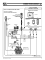
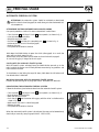
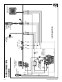
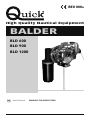
REV 000A
High Quality Nautical Equipment
BALDER
BLD 600
BLD 900
BLD 1200
GB
User's Manual
WINDLASS FOR INSIDE/STERN
GB
Pag. 14
Pag. 15
Pag. 16
Pag. 17
Pag. 18
INDEX
Technical data
Installation
Connection diagram 600W
Connection diagram 900/1200W
Free Fall Usage
BALDER 600/900/1200 - REV000A
Pag. 19
Pag. 20
Pag. 21
Pag. 22/23
Usage - Warning
Installation: rope fall positioning
Installation: fixing of the automatic stop
Maintenance
TECHNICAL DATA
GB
MODELS
BALDER 600
BALDER 900
600W
900W
MOTOR OUTPUT
Motor supply voltage
12 V
Maximum working load
Maximum speed
24 V
1200W
24 V
12 V
24 V
200 Kg (440,9 lb)
320 Kg (705,5 lb)
480 Kg (1058,2 lb)
25-28 m/min (82-91 ft/min)
22-25 m/min (72-82 ft/min)
28-30 m/min (91-98 ft/min)
16 mm2 (AWG5) 10 mm2 (AWG7) 25 mm2 (AWG7) 10 mm2 (AWG7) 35 mm2 (AWG2) 16 mm2 (AWG5)
Motor cable size (1)
Protection circuit breaker (2)
60 A
40 A
Deck thickness (3)
50 A
40 A
80 A
50 A
20 ÷ 30 mm (25/32” ÷ 1” 3/16 ft)
Weight
9,0 Kg (19.8 lb)
14,6 Kg (32.2 lb)
Rope size (4)
(1)
(2)
(3)
(4)
12 V
BALDER 1200
19,2 Kg (34.6 lb)
• 12 mm • 14 mm • 16 mm
Minimum allowable value for a total length L<20m (see pag. 24/25). Determine the cable size according to the length of the wiring
With circuit breaker designed for direct currents (DC) and delayed-action (thermal-magnetic or hydraulic-magnetic).
On request, studs can be supplied for greater deck thicknesses.
Recommended leaded rope.
DIMENSIONS OF MODELS mm ( inch )
141 (5 9/16)
141 (5 9/16)
119 (4 11/16)
44 (1 3/4)
BLD 1200
44 (1 3/4)
BLD 900
44 (1 3/4)
BLD 600
128 (5 3/64)
128 (5 3/64)
Ø 106 (4 11/64)
111 (4 3/8)
128 (5 3/64)
Ø 106 (4 11/64)
111 (4 3/8)
82 (3 7/32)
111 (4 3/8)
Ø 106 (4 11/64)
162 (6 1/4)
162 (6 1/4)
244 (9 5/8)
330 (13)
340 (13 3/8)
Ø 130 (5 1/8)
42 (1 21/32)
48 (1 57/64)
33,5 (1 5/16)
Ø 150 (5 29/32)
102 (4 1/64)
BALDER’S ACCESSORIES for inside/stern installations
8 (5/16)
Ø 45 (1 49/64)
153 (6 1/32)
140 (5 33/64)
Thru-hull
F
14
Automatic Stop
Mounting bracket
Quick® reserves the right to introduce changes to the equipment and the contents of this manual without prior notice.
In case of discordance or errors in translation between the translated version and the original text in the Italian language, reference will be made to the Italian or English text.
BALDER 600/900/1200 - REV000A
INSTALLATION
GB
BEFORE USING THE WINDLASS READ THESE INSTRUCTIONS CAREFULLY.
IF IN DOUBT, CONTACT YOUR NEAREST “QUICK®” DEALER.
WARNING: the Quick® windlasses are designed to weigh the anchor.
Do not use the equipment for other purposes.
Quick® shall not be held responsible for damage to equipment
The windlass is not designed for the loads that
and/or personal injury, caused by a faulty use of the equipment.
Always deactivate the windlass when not in use.
might occur in extreme weather conditions (storms).
Check that there are no swimmers nearby before dropping anchor.
For improved safety we recommend installing at least two anchor windlass controls in case one is accidentally damaged.
We recommend the use of the Quick® hydraulic-magnetic switch as the motor safety switch.
The contactor unit
or reversing contactor unit must be installed in a point protected from accidental water contact.
Secure the rope with a further device before starting the navigation.
To prevent accidental releases, the anchor
Isolate the windlass from the power symust be secured. The windlass shall not be used as the only securing device.
stem during navigation (switch the circuit breaker off) and lock the chain securing it to a fixed point of the boat.
THE PACKAGE CONTAINS: windlass - contactor unit or reversing contactor unit - base gasket - drill template - handle - bolts
and screws (for assembly) - user’s manual - conditions of warranty.
TOOLS REQUIRED FOR INSTALLATION: drill and drill bits: Ø 9 mm (23/64"); Ø 60 mm (2 3/8”) hollow mill;
hexagonal wrenche: 13 mm.
“QUICK®”ACCESSORIES RECOMMENDED: anchoring RL control board (mod. 800) - Waterproof hand helds R/C (mod.
HRC1002) - Foot switch (mod. 900) - Hydraulic-magnetic circuit breaker - Radio control RRC (mod. R02, PO2, H02).
COVER INSTALLATION
INSIDE/STERN INSTALLATIONS
Ensure that the upper and lower surfaces of the deck are
as parallel as possible; If this is not the case, compensate
the difference appropriately (a lack of parallelism could
result in a loss of motor power).
The deck thickness must be included among the figures
listed in the table.
In cases of other thicknesses it is necessary to consult a
Quick® retailer.
There must be no obstacles under deck to the passage
of cables and rope; lack of depth of the peak could cause
jamming.
The mounting bracket allows the user to install the
windlass in a variety of combinations.
The motorgearbox can be rotated and fixed in several
positions every 45°.
WARNING: before wiring up, be sure the electrical cables are not live.
BALDER 600/900/1200 - REV000A
15
GB
CONNECTION DIAGRAM
QUICK® ACCESSORIES
FOR WINDLASS OPERATION
BASIC SYSTEM BALDER 600W
REMOTE RADIO CONTROLS
SEE PAGE 20 SHOWING
THE MAIN CONNECTION DIAGRAM
MULTI-PURPOSE
WATERTIGHT HAND HELD
REMOTE CONTROL
MOD. HRC 1002
RECEIVERS
AUTOMATIC
STOP
FUSIBILE
1A
TRANSMITTERS
WINDLASS
RADIO POCKET
HAND SET
FOOT SWITCHES MOD. 900U AND 900D
-
BLUE
BROWN
BLACK
ROSSO
NERO
MOTOR
BLACK
BROWN
BLUE
+
BATTERY
FUSE
4A (12V)
2A (24V)
L1
HYDRAULIC-MAGNETIC
CIRCUIT BREAKER
(see table on page 14)
L5
REVERSING
CONTACTOR UNIT
MOD. T6411-12 (12V)
C
16
L3
L4
BLU
BLU
L2
A2
L = L1 + L2 + L3 + L4 + L5
BALDER 600/900/1200 - REV000A
CONNECTION DIAGRAM
GB
QUICK® ACCESSORIES
FOR WINDLASS OPERATION
BASIC SYSTEM BALDER 900/1200W
REMOTE RADIO CONTROLS
SEE PAGE 21 SHOWING
THE MAIN CONNECTION DIAGRAM
MULTI-PURPOSE
WATERTIGHT HAND HELD
REMOTE CONTROL
MOD. HRC 1002
RECEIVERS
AUTOMATIC
STOP
TRANSMITTERS
FUSIBILE
1A
WINDLASS
RADIO POCKET
HAND SET
FOOT SWITCHES MOD. 900U AND 900D
BLUE
BROWN
BLACK
ROSSO
NERO
MOTOR
L2
BLACK
BROWN
-
BLUE
+
BATTERY
FUSE
4A (12V)
2A (24V)
L3
HYDRAULIC-MAGNETIC
CIRCUIT BREAKER
(see table on page 14)
L1
BLU
C
BLU
BALDER 600/900/1200 - REV000A
L4
L1
CONTACTOR UNIT
MOD. T6315-12 (12V)
MOD. T6315-24 (24V)
A2
L = L1 + L2 + L3 + L4
17
GB
FREE FALL USAGE
AUTOMATIC FREEFALL SYSTEM
FIG. 1
ATTENTION: the automatic system should be activated or deactivated
with the clutch closed (engaged) to avoid damage to the electromechanical components.
B
ATTIVAZIONE SISTEMA AUTOMATICO DI CADUTA LIBERA
Con questa procedura si attiva il sistema automatico di caduta libera.
•
•
•
•
•
•
•
Turn the cover A until the pin’s hole B faces upwards (as shown in fig. 1).
Shut off power to the windlass.
Block the rope with a lock.
Pull the knob C until the pin is completely out B (as shown in fig. 2).
Make certain the clutch is closed (engaged).
Release the rope.
Turn power to the windlass back on.
C
A
FIG. 2
B
Hold down the DOWN button to open the clutch (disengaged). As a result the
gypsy will turn freely around its axis.
On the other hand, hold down the UP button to close the clutch (engaged).
As a result, the gypsy is integral to the axis again.
Casting with the automatic freefall system
With the freefall system activated, keep the DOWN button pressed up to the
point in which the anchor can fall freely without encountering any problems and
then release the button.
C
A
To slow down or stop letting the rope fall down, hold down the UP button until
the desired effect is obtained.
Weighing the anchor with the automatic freefall system
Perform the procedure given in paragraph USAGE - WEIGHING THE ANCHOR.
DEACTIVATING THE AUTOMATIC FREEFALL SYSTEM
Follow the directions given below to deactivate the automatic freefall system:
FIG. 3
Turn the cover A until the pin’s hole B faces upwards (as shown in fig. 1).
Shut off power to the windlass.
Block the rope with a lock.
Push the pin B , into the center of the gypsy with the aid of a suitable tool (as
shown in fig. 3).
• Make certain the clutch is closed (engaged).
• Release the rope.
• Turn power to the windlass back on.
•
•
•
•
When the automatic freefall system is deactivated, the rope can be lowered only
electrically or manually (see paragraph USAGE - CLUTCH USE).
18
B
C
A
BALDER 600/900/1200 - REV000A
WARNING - USAGE
GB
WARNING
WARNING: stay clear of the chains, ropes and gypsy. Make sure the electric motor is off when windlass is used
manually (even when using the handle to disengage the clutch). In fact people with windlass remote controls
(hand-held remote control or radio-controlled systems) might accidentally operate it.
WARNING: secure the rope with a device before starting the navigation.
WARNING: do not operate the windlass by using the electrical power when the handle is inserted in the drum or
into the gypsy cover.
WARNING: Quick® recommend using a circuit breaker designed for direct current (DC) with delayed-action
(thermal-magnetic or hydraulic-magnetic) to protect the motor supply line from overheating or short circuits. The
circuit breaker can be used to cut off power to the windlass control circuit and so avoid accidental activation.
CLUTCH USE
The clutch (23) provides a link between the gypsy and the main shaft (2 or 4). The clutch can be released (disengagement) by using the handle (28) which, when inserted into the gypsy cover (26), must be turned counter-clockwise. The
clutch will be re-engaged by turning it clockwise.
WEIGHING THE ANCHOR
Turn on the engine. Make sure the clutch is engaged and remove the handle. Press the UP button on the control provided. If the windlass stops and the hydraulic magnetic switch (or thermal cutout) has not tripped, wait a few seconds
and try again (avoid keeping the button pressed).
If the hydraulic magnetic switch, has tripped, reset it and wait a few minutes before weighing anchor once again.
If, after a number of attempts, the windlass is still blocked, we suggest to move the boat to release the anchor.
Check the upward movement of the chain for the last few meters in order to avoid damages to the bow.
CASTING THE ANCHOR
The anchor can be cast by using the electrical control or manually. To operate manually, the clutch must be disengaged
allowing the gypsy to revolve and letting the rope or chain fall into the water.
To slow down the chain, the handle must be turned clockwise. To cast the anchor by using the electrical power, press
the DOWN button on the control provided.
In this manner, anchor casting is under control and the chain and rope unwind evenly. In order to avoid any stress on the
windlass -once the boat is anchored- fasten the chain or secure it in place with a rope.
BALDER 600/900/1200 - REV000A
19
GB
INSTALLATION
ROPE FALL POSITIONING
According to the windlass installation, the rope may have different angles.
Here following is the procedure to follow in order to adapt the rope guide support (21) at the rope outlet.
Unscrew and remove the pin (15) and the screw (27).
15
27
21
Unscrew and remove the gypsy lid (26) and the gypsy (24).
Unscrew and remove the 4 screws (18) and rotate the base
plate (14) till the desired position.
17
18
24
20
26
BALDER 600/900/1200 - REV000A
INSTALLATION
GB
FIXING OF THE AUTOMATIC STOP TO THE ROPE
• Weigh anchor till it blocks in the Bow Roller.
• With the rope under strain, position the Automatic Stop as close as possible to the thru-hull, measure the distance between
the Automatic Stop and the Bow roller pin.
• n the established spot of the rope, fix the Automatic Stop with the 4 screws (see fig. 1).
Thru-hull
Rope
Automatic Stop
Bow Roller
Hull
Anchor
FIG.1
Rope
Automatic Stop
ZSBSCBLD0000
BALDER 600/900/1200 - REV000A
21
GB
MAINTENANCE
GASKET/JIG
Only for installation of Balder on deck
4
29
5
1
6
7
8
3
9
10
2
17
11
12
11
13
8
18
22
23
15
26
16
14
19
20
21
25
27
24
28
22
BALDER 600/900/1200 - REV000A
MAINTENANCE
POS. DESCRIPTION
CODE
1
Mounting bracket “BLD” Ø105
al anod
MMSTFSBLDA00
2
Shaft series “BLD” Ø105 600W
MSAS06209R00
3
Key 6*6*50 Stainless steel
MBH060650X00
4
Shaft series “BLD” Ø105 900W
MSAS09239R00
5
Key 6*6*50 Stainless steel
MBH060650X00
6
Stud M8 x 60
MBP08600X00
7
Anodized base “BLD” Ø105
SGMSCBBLD105
8
Oil seal 25*42*7mm
PGPRL2542700
9
Bearing 61805
MBJ616050000
10
Internal circlip
MBAN3715Y000
11
External circlip
MBAE2520Y000
12
Bearing 61905
MBJ619050000
13
Internal circlip
MBAN4217Y000
14
Base plate
“BLD” Ø105 Stainless steel
SGMSCBBLD105
15
Mooring rope puller lock pin
“BLD” Ø105 Stainless steel
SPMSNPBLD105
16
Stainless steel hex.
cheese–headed screw M 6*18
MBV0618MXCE0
17
Washer Ø 05 Stainless steel
MBR05X000000
18
Screw M 5*16 Stainless steel
T cilind cava esag
MBV0516MXCE0
19
Mooring rope puller “BLD” Ø105
Stainless steel
20
Spring for mooring rope puller
windlass 800W “AS/C”
Stainless steel
MMTND08ASC00
21
Rope guide support
“BLD” DX Stainless steel
SPMSNBLDDXX0
22
Washer reinforcement
MBR254025X00
23
Clutch cone 800W “AS/C”
MSF08ASCN000
24
Gypsy 800W “BLD”
complete rope
ZSB08CMBLDR0
25
Rope/chain stripper “BLD” Ø105
Stainless steel
26
Gypsy cover “G” FF
complete
SAKCPBBGFF00
27
Screw M 8*30 Stainless steel
T cilind cava esag
MBV0830MXCE0
28
Windlass lever - Nylon
PVLVSDN00000
29
Gasket/jig
PGBSTB050000
BALDER 600/900/1200 - REV000A
GB
WARNING: make sure the electrical power to the motor
is switched off when working manually on the windlass.
Carefully remove the rope from the gypsy.
Quick® windlasses are manufactured with materials resistant
to marine environments. In any case, any salt deposits on the
outside must be removed periodically to avoid corrosion and
damage to the equipment. The parts where salt may have built
up should be washed thoroughly with fresh water.
Once a year, the drum and the gypsy are to be taken apart as
follows:
Use the handle (28) to unscrew the gypsy cover (26); loosen
screw (27) and take off the gypsy cover.
Loosen the screws (16) of the chain stripper (25) and remove it;
remove the gypsy (24).
Clean all the parts removed to avoid corrosion, and grease the
shaft thread (2, or 4) and the gypsy (24) where the clutch cones
(23) rest (use grease suitable for marine environment).
Remove any oxide deposits from the terminals of the electric
motor and the contactor unit or reversing contactor unit; grease
them.
SPMMTCBLD000
SPMSNBLD1050
23
24
RED
BLACK
BATTERY
MOTOR
L5
L4
C
HYDRAULIC
MAGNETIC
CIRCUIT BREAKER
(see table on page 4/12)
AUTOMATIC
STOP
L2
QUICK® WINDLASS
BALDER 600W
MAIN CONNECTION
DIAGRAM
L1
L3
A2
REVERSING
CONTACTOR UNITS
MOD. T6415-12 (12V)
MOD. T6415-24 (24V)
FUSE
4A (12V)
2A (24V)
MOD. 900/D
DOWN
MOD. 900/U
UP
FOOT SWITCH
BLUE
BROWN
BLACK
MULTI-PURPOSE
WATERTIGH
HAND HELD
REMOTE
CONTROL
MOD. HRC 1002
L = L1 + L2 + L3 + L4 + L5
WINDLASSES
CONTROL BOARD
MOD. 800
RADIO RECEIVER RRC
MOD. R02 (2CH)
UP
DOWN
+
-
BLUE
BROWN
BLACK
BLUE
BROWN
BLACK
FUSE 1A
BLUE
BLUE
BALDER 600/900/1200 - REV001A
BALDER 600/900/1200 - REV001A
FUSE 1A
RED
BLACK
BATTERY
MOTOR
L1
C
HYDRAULIC
MAGNETIC
CIRCUIT BREAKER
(see table on page 4/12)
L2
AUTOMATIC
STOP
L4
QUICK® WINDLASS
BALDER 900/1200W
MAIN CONNECTION
DIAGRAM
L3
L1
MOD. 900/U
UP
BROWN
BLACK
MULTI-PURPOSE
WATERTIGH
HAND HELD
REMOTE
CONTROL
MOD. HRC 1002
L = L1 + L2 + L3 + L4
BLUE
A2
REVERSING
CONTACTOR UNITS
MOD. T6415-12 (12V)
MOD. T6415-24 (24V)
FUSE
4A (12V)
2A (24V)
MOD. 900/D
DOWN
FOOT SWITCH
WINDLASSES
CONTROL BOARD
MOD. 800
RADIO RECEIVER RRC
MOD. R02 (2CH)
UP
DOWN
+
-
BLUE
BROWN
BLACK
BLUE
BROWN
BLACK
BLUE
BLUE
25
BALDER
R00A
BLD600 BLD900 BLD1200
GB
Product code and serial number
QUICK® S.p.A. - Via Piangipane, 120/A - 48124 Piangipane (RAVENNA) - ITALY
Tel. +39.0544.415061 - Fax +39.0544.415047
www.quickitaly.com - E-mail: [email protected]