1
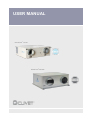
ELFOFresh2
CPAN-U 70 - 650
MAKE UP AND PURIFICATION UNIT WITH ACTIVE THERMODYNAMIC RECOVERY
FOR INDOOR INSTALLATION
Installation and operating manual
ELFOFresh2 70-120
ELFOFresh2 200-650
M05E40M12-04
19-11-2014
Dear Customer,
We congratulate you on choosing an ELFOSystem product, the air
conditioning system at annual cycle that offers the possibility in a sole
system of meeting all the heating, conditioning and domestic hot water
needs, purifies and renews the air
Clivet is being working for years to offer systems able to assure the
maximum comfort for long time with high reliability, efficiency , quality and
safety. The target of the company is to offer advanced systems, that assure
the best comfort, reduce the energy consumption, the installation and
maintenance costs for all the life-cycle of the system.
With this manual, we want to give you information that are useful in all the
phases: from the reception, to the installation and use until the disposal so
that a system so advanced offers the best procedure of installation and use.
Best regards and have a nice reading !
CLIVET Spa
2
1 - GENERAL
It is advisable to read it carefully so you will save time during
operations.
Follow the indications so you will not cause damages to things
and injuries to people
Before going ahead with operations, read the GENERAL
WARNINGS on page 78
Pay particular attention to :
WARNING, identifies particularly important operations or
information
PROHIBITIONS, identifies operations that must not be
carried out, that compromises the operating of the unit or
may cause damages to persons or things.
3
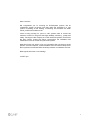
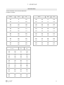
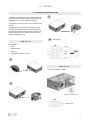
1
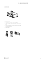
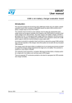
DAIR50X - DAIR80X
AIRJET 50/I - 80/l supply diffuser white frame and black inside
2
GAIR50X - GAIR80X
Intake grille + extractable filter AIRJET
50/A - 80/A - white frame and black
inside
9
TFT90X
10
CPRX
40
PRX
39
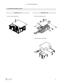
GPRX
Soundproofed plenum for air
recirculation
Manifold for DN150-200 air
recirculation plenum
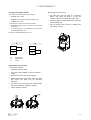
IT90X
Insulation in a 20mt. coil for
DN90 round flexible tube
11
3
41
DN90 round flexible tube (Int. diam.
78mm) in a 20m. coil without insulation
CBT90X
Connector to distribution box for
DN90 round tube
PAIR50X- PAIR80X
Suction/supply plenum with AIRJET 50
- 80 control damper - rear connection
12
GIUTX
Connecting joint for DN90 round tube
4
GINOX - GIVEX
Suction/supply rectangular grill
350x130mm stainless or white
13
CT90X
Printed curve of 90-degree angle for
DN90 round tube
5
FREX
Filter for rectangular grilles 350x130mm
(5 pcs.)
14
A90DTX
90-degree adaptor, double DN90 round
tube for DN125 valve + cap
6
VIEX
Extraction/intake valve in ABS DN125
without air filter
7
FT125X
Filter for DN125 valve (5 pcs.)
15
TACTX
Cap for DN90 round tube (5 pcs.)
17
8
GQIEX
Extraction/intake squared grill of
DN125 joint with air filter
16
ANFTX
DN90 seal O-Ring (10 pcs.)
TFIS150X - TFIS200X TFIS250X
DN150/200/250 soundproofing insulated
flexible tube in a 10mt. coil
18
GR150X-GR200X- GR250X
Exhaust / return squared wall grig with
circular coupling DN150/200/250
19 GF150X
GF200X
GF250X
Grill for recirculation air
return plenum 325x175
mm white
38
BD14CX
37
14-output distribution box,
DN200 joint
BD8CX
36
8-output distribution box,
DN150-200 joint
TFPNX
Flat flexible tube 132x52mm
in a 20m. coil without insulation
35
IT100X
Insulation in a 20mt. coil
for flat flexible tube 132x52
34
COBPX
DN90 connector joint
(CBT90X) --> flat tube
33
GIUPX
Seal and connecting joint
for flat tube (10 pcs.)
32
28
RTPTX
Round/flat tube connecting joint
27
REPPX
Flow controller for flat tube
26
ANFPX
Fixing ring for flat tube (10 pcs.)
25
TACPX
Cap for flat tube (5 pcs.)
CVP90X
Vertical 90-degree curve
for flat tube
24
A90GPX
90-degree adaptor, single tube for
flat grill 350x130 mm
31
COP90X
Horizontal 90-degree curve
for flat tube
23
30
CTP180X
ADMPX
Straight adaptor, single flat tube for
DN125 valve
Joint for 180-degree
flat tube rotation
A90MPX
90-degree adaptor, single tube for
DN125 valve
R2015X - R2520X
DN200-DN150 reducer
DN250-DN200 reducer
21
A90DPX
90-degree adaptor, double flat tube
for DN125 valve
DY200X
DN200-DN200-DN200 Y-joint
DY250X
DN250-DN200-DN200 Y-joint
ELFOAir
MTOA40M14-00
20
F/F DN150/200/250
joint
22
19-11-14
29
!
!
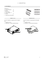
Cover the plenum with cardboard, adhesive tape, etc.
!
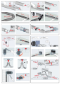
1 - GENERAL
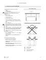
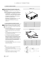
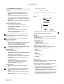
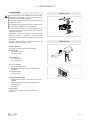
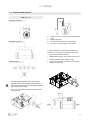
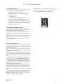
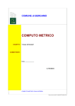
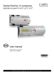
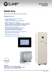
1.1 UNIT DESCRIPTION
CPAN-U 70 - 120
CPAN-U 200 - 650
7
Electrical remote panel
It is possible to remove the electrical panel and
make it remote to facilitate the installation
8
External exchanger
It recovers energy (heat / cool) from the exhaust air.
9
Air filter
It purifies the fresh air before introducing it into the
rooms
1
Serial number label
2
Exhaust air fan
It rejects the unhealthy air outdoors.
3
Internal exchanger
It transfers energy (heat / cool) to the fresh air .
4
Compressor
5
Supply fan
It blows treated air in the rooms.
10
Upper panel
Humidity probe
11
Electronic filter (option)
12
Electrical panel
6
8
1 - GENERAL
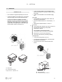
1.2 ACCESSORIES
CDPX : Discharge condensate pump (size 70-650)
EHPCX : Preheating elements 0,7 kW in duct (size 70-120)
Preheating elements 1,5/3 kW in duct (size 200-650)
FSEX : Electronic filter kit (size 70-650)
HSE3LX: Immersed electrode steam humidifier for Elfofresh DN250 (size 200-300)
HSE3MX: Immersed electrode steam humidifier for Elfofresh DN250 (size 500-650)
FAEX : Kit of exhaust air filter (size 200-650)
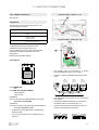
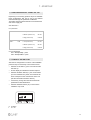
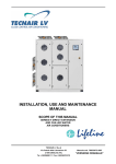
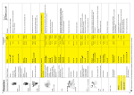
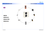
ELFOAir
Is the air distribution system.
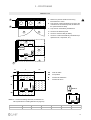
CPAN-U 70 - 120
1
Ambient exhaust air
6
Customer connections
2
Grid to prevent small animals or leaves from
entering inside (provided by the customer)
7
Electronic filter (option)
8
Exhaust air filter
3
Outdoor air intake
9
Ambient air intake
4
Kit of electric resistance (option)
10
Ambient air supply
5
Intake air filter
11
HID-P1 ambient thermostat
9
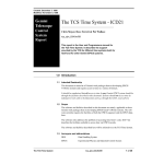
1 - GENERAL
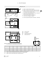
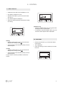
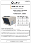
CPAN-U 200 - 650
1
Ambient exhaust air
2
Grid to prevent small animals or leaves from entering inside (provided by the customer)
3
Outdoor air intake
4
Kit of electric resistance (option)
5
Remote electrical panel
6
Filter extraction with remote electrical panel
7
Electronic filter (option)
8
Filter extraction with built-in remote electrical panel
9
Kit of exhaust air filter (optional)
10
Ambient air intake
11
Humidifier kit (optional)
12
Ambient air supply
13
HID-P1 ambient thermostat
10
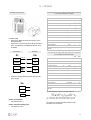
1 - GENERAL
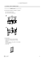
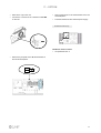
1.3 UNIT IDENTIFICATION
Serial number label
The serial number label is positioned on the unit,
generally next to the electrical panel, and allows you to
indentify all the unit features.
The serial number label has not to be removed for any
reason.
It reports the regulations indications such as:
• Type of unit
series
→
CPAN-U
• size →
70.......650
• serial number
xxxxxxxxxxxx
• year of manufacture
• wiring diagram number
• electrical data
• manufacturer logo and address
Serial number
It identifies uniquely each unit.
It identifies specific spare parts for the unit.
Intervention requests
Note data from the serial number label and write them
in the table sideways, so you will find them easily when
needed.
In case of intervention you have to provide the data
indicated sideways.
Serie
Size
Serial number
Year of manufacture
Wiring diagram
11
2 - RECEPTION
2.1 DELIVERY CONTROL
Before accepting the delivery you have to check:
acceptance — clear evidence of deficiencies/damages
• that the unit hasn’t been damaged during transport
during transport".
• that the materials delivered correspond with that
• Contest by fax and registered mail with advice of
indicated on the transport document comparing the
receipt to supplier and the carrier.
data with the identification label ‘A’ positioned on the
Any disputes must be made within the 8 days owing the
packaging.
delivery. Complaints after this period are invalid.
In case of damage or anomaly:
• write down on the transport document the damage you
found and quote this sentence: "Conditional
CPAN-U 200 - 650
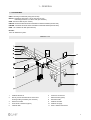
CPAN-U 70 - 120
The following examples are indications; the choice of
the means and of the handling modes will depend on
factors, such as:
•
The unit weight
•
Type and overall dimensions of the unit
•
Place and route for the handling (dirt yard,
asphalted square, etc.)
•
Condition of the place of destination (roof, square,
etc.) distances, drops and gradients.
A
A
A
•
Lifting with forks:
•
Insert the forks as indicated in the figure.
•
During the handling is forbidden to exceed the maximum allowable inclination as indicated in the figure.
•
It is forbidden to lift simultaneously more packages
letting them looses.
•
In case of lifting of more units at the same time, an
appropriate container must be used.
Do not trample
30°
clivet
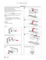
PackAGing removing
• Cut the fixing strips.
• Remove the packaging lifting it upwards.
Do not leave loose packages during the transport
• Remove the protective nylon.
12
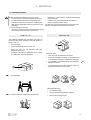
2 - RECEPTION
2.2 KIT REMOVAL
Installation kit
A spring antivibrations
n.4
B M8 nuts
n.4
C plain washers
n.4
A
B
C
D
D toothed washers n.4
E M8 bolts
G
F
n.4
E
F ambient thermostat (option)
CPAN-U 70 - 120
CPAN-U 200 - 650
The unit is supplied in a single pack and is equipped
with:
The unit is supplied in a single pack and is equipped
with:
1 installation manual
1 installation manual
2 installation kit - ambient thermostat (option)
2 installation kit - ambient thermostat (option)
1
2
13
3 - POSITIONING
3.1 CLEARANCE ACCESS RECOMMENDED
The unit has been designed to be installed :
•
indoor
•
in fixed position
UNIT IN BUBBLE LEVEL
The unit can not be installed outdoor or in a room /
compartment where the temperature can drop
below 0 ° C.
Installation criteria:
•
safe accessible position
•
customer approval
•
avoid flood-prone places;
•
verify the unit weight and bearing point capacity;
•
verify that all bearing points are aligned and levelled
•
unit in bubble level
•
plan in the false ceiling (or in the floor) the openings indicated in the functional clearances to allow
the access to the unit for the maintenance operations
•
Ceiling positioning : let free the projection to the
ground of the unit and of the functional clearances
to allow the access with ladders or other means
•
Floor positioning : install the unit raised from the
ground .
AVOID RECIRCULATION OF EXHAUST/RETURN AIR
Limit vibration transmission:
•
use antivibration
supporting points
•
install flexible joints on the hydraulic/aeraulic connections.
devices
on
unit
bearing/
The functional clearances have to :
•
guarantee the unit good operating
•
allow the maintenance operations
•
safeguard the authorized operators and the exposed person.
•
position the unit taking into consideration the clearances indicated in the figure.
•
consider the space necessary for return ambient
filter extraction (see option).
AE
fresh air intake
ES
air expulsion
M
Ambient air distribution
R
Ambient air return
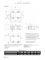
14
3 - POSITIONING
CPAN-U 70 - 120
A
A Distance to prevent vibrations from being
transmitted min. 15mm.
D
B Trap door for routine maintenance (access to the
connections of the electrical panel, air filters and
the optional electronic filter)
A
C Trap door for extraordinary maintenance
B
D Access to the electrical panel
C
E Access to clean the filter (air filters)
F Access to conduct extraordinary maintenance (to
replace the fan, compressor, etc.)
E
D
E
F
A
L
L1
L2
W1
AE
ES
M
R
AE
fresh air intake
ES
air expulsion
M
Ambient air distribution
R
Ambient air return
W
Heat. el.
W2
Heat. el. = If there are heating elements, increase the W1
value (information on heating elements on page 65)
AE
ES
M
R
Mod
L1
L
L2
W1
W
W2
70 - 120
20 mm
800 mm
500 mm
300 mm
590 mm
300 mm
15
3 - POSITIONING
CPAN-U 200 - 650
A Space to access the electrical panel
B
B Space necessary for the by-pass damper min. 20mm.
A
C Distance to prevent vibrations from being transmitted
min. 20mm (insert a neoprene sheet)
C
D Trap door for routine maintenance (access to electrical
panel and optional electronic filter)
G
D
E Accesso per manutenzione straordinaria
F Accesso per smontaggio ventilatore
G Accesso per pulizia filtro (filtro aria espulsa - opzionale)
E
F
A
G
F
C
L2
L
L1- A - B - C
W1
AE
AE
fresh air intake
ES
air expulsion
M
Ambient air distribution
R
Ambient air return
ES
W
Heat. el.
M
R
W2
Heat. el. = If there are heating elements, increase the W1
value (information on heating elements on page 67)
L1A
L1B
L1C
AE
ES
M
R
Mod
L1A
L1B
L1C
L
L2
W1
W
W2
200
700 mm
400 mm
200 mm
920 mm
20 mm
300 mm
704 mm
300 mm
300
700 mm
400 mm
200 mm
920 mm
20 mm
300 mm
704 mm
300 mm
500
700 mm
400 mm
200 mm
1158 mm
20 mm
300 mm
741 mm
300 mm
650
700 mm
400 mm
200 mm
1158 mm
20 mm
300 mm
741 mm
300 mm
Space to access the electrical panel when it is positioned on the machine
Space to take out the side filter when the panel is in a remote position
Space to take out the humidity probe and replace the fan
16
3 - POSITIONING
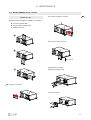
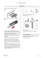
3.2 CEILING POSITIONING
3.3 FLOOR POSITIONING
•
Fix some M8 threaded bars (not supplied) to the
ceiling.
•
Insert the M8 threaded bar on the support base.
•
Pass the M8 threaded bars in the brackets on the
unit.
•
Match the upper hole of the antivibration device
with the hole of the support bracket.
•
Insert and screw on the tapped bar the spring
antivibration device.
•
The antibration device must be positioned with the
interior threaded upward.
•
The antibration device must be positioned with the
interior threaded downward
•
Insert the flat and notched washer in the bolt.
•
•
Insert the flat and notched washer and screw the
nut to lock.
Screw the bolt in the top of the antivibration device
letting it pass through the hole on the bracket.
•
•
Avoid to over tighten the nuts, the springs, because
if too much crushed they don’t absorb vibrations.
Do not over tighten the nuts, the springs, because if
too much crushed they don’t absorb vibrations
CPAN-U 70 - 120
CPAN-U 70 - 120
CPAN-U 200 - 650
CPAN-U 200 - 650
A
threaded bar
D
flat washer
B
bracket
E
notched washer
C
antivibration foot
F
nut
bolt
D
bracket
B
notched washer
E
antivibration foot
C
flat washer
F
threaded bar
A
17
3 - POSITIONING
3.4 ELECTRIC PANEL
CPAN-U 70 - 120
CPAN-U 200 - 650
The electrical panel is provided assembled on the unit
side but if necessary it can be remotely controlled up to
2 mt. away.
B
A
Access to the electrical panel:
A
from below
B
lateral
Remote positioning
•
Unscrew the fixing screws and remove the
electrical panel cover.
•
Unscrew the fixing screws (M6) and remove the
panel from the unit side.
•
Fix the panel using screws and screw anchors
suitable for the characteristics of the used support.
•
If later it is supposed the installation of the electric
elements (optional) consider that the cable to
connect to the electrical panel has a max length of
1,5 metres.
•
In this case the filter removal for cleaning can be
performed either from the side or from below.
Electric panel
L = 2mt
325
120
252
18
3 - POSITIONING
3.5 ACCESS TO INTERNAL PARTS
CPAN-U 70 - 120
Access from the upper side
CPAN-U 200 - 650
Access from the upper side
Access from the bottom side
19
3 - POSITIONING
3.6 AMBIENT THERMOSTAT
The choice of the installation point is decisive for the
environmental comfort and the energy consumption.
The thermostat must be placed :
•
In a room with medium temperature and humidity
conditions, representative of the other rooms
21.0
REMOTE
ECO
AUTO
•
at a height of 150 cm
next to heat sources
•
points exposed to direct sunlight
•
in a position with air rejected from outlets or
diffusers
•
behind curtains or pieces of furniture
•
near windows and doors to the outside
•
on walls crossed by fireplaces or heating ducts
•
on external walls.
OK
an
Cle
•
o
Ec
• preferably on an internal wall
Positions to avoid :
1,5 m
20
4 - WATER CONNECTIONS
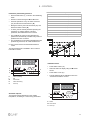
4.1 CONDENSATE DISCHARGE
CPAN-U 200 - 650
The condensate must be disposed in order to avoid
damages to people and things.
•
Unit discharge fitting: the connection must not
transmit mechanical stresses and must be
performed taking care not to damage the unit
discharge fitting.
•
Provide a siphon that, eliminating the negative
pressure caused by the fan, prevents the air intake
from the discharge duct.
•
The ducting must have a min. slope of 5% to allow
the runoff.
•
Anchor the ducting with an adequate number of
supports.
•
Otherwise are generated duct failures and air locks
that prevent the runoff.
•
Insulate the duct and the siphon to avoid the
condensate drippings.
•
Connect the condensate discharge to a sewerage
drainage network. DO NOT use white water or
drainage networks to avoid the aspiration of odours
in the case of evaporation of water contained in the
siphon.
•
The connection must not be hermetic, so as to
allow the venting and avoid possible liquid returns.
•
Check at the end of the work, the regular
condensate runoff pouring some water in the tray.
B
B Condensate discharge fitting
Ø 26 mm
Condensate discharge pump - option (page 72)
Siphon
Siphon height calculation
T = 2P
S = T/2
P is the pressure determined by the fan in
correspondence of
the condense collection bowl (approx. 1 mm = 9.81 Pa)
P
CPAN-U 70 - 120
Example:
H
T
S
A
P = 300 Pa = 30 mm
T = 2P = 60 mm
S = T/2 = 30 mm
4.2 RISK OF FREEZE
Prevent the risk of freeze if the unit, drain or plumbing
connections of the humidifier can be subject to
temperatures close to 0°C.
For example:
A Condensate discharge fitting
Ø 16 mm
Condensate discharge pump - option (page 72)
•
safeguard the pipes with heating cables placed
under the insulation .
•
insulate the pipes.
•
perform the installation draining if unused for long
periods.
•
provide the antifreeze resistance in case of rigorous
temperatures.
21
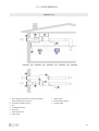
5 - AERAULIC CONNECTIONS
5.1 AERAULIC DESIGN CRITERIA
The dimensioning and the correct execution of the
aeraulic connections are critical to ensure the unit
operating and an appropriate level of quietness in the
served area.
Here are some indications, as a simple checklist to
support the installer and the designer of the installation.
•
CPAN-U 70 - 120
A
AIR RENEWALS = 0,5 volumes per hour , max 1
volume per hour ; in the volume are not considered
the extraction rooms (kitchens, bathrooms, etc.)
•
AIR SPEED included between 2 and 3 m/sec (it
guarantees the system silence)
•
RETURN AIR in the kitchens / bathrooms / rooms
with vapours, unpleasant odours
•
SUPPLY AIR in the living room , bedrooms ,
studies etc....
D
B
C
Size
5.2 AIR DISTRIBUTION / EXHAUST SYSTEM
If the duct outlets for the outdoor air inlet and exhaust
are outside of coverage, must end with a 90 ° bend
downward, to prevent entry of water from the air inlet.
70-120
A
Air exhaust
Ø 150 mm
B
Ambient air return
Ø 150 mm
C
Ambient air distribution
Ø 150 mm
D
Fresh air intake
Ø 150 mm
To perform the ductings:
•
Connect the ductings fixing them to the connections
with the special hookings to the circular flanges.
•
The duct weight should not lie on the connection
flanges.
A
•
The ducts should not be tilted towards unit to avoid
the condensate and water return.
D
•
Put antivibration joints between ducts and units.
•
The connection to the flanges and among the
different duct sections must guarantee the air seal,
avoiding air dispersions in supply and return that
penalize the overall efficiency of the installation.
•
Limit the pressure drops by optimizing the path, the
type and the number of curves and branches.
•
Use curves of large radius.
•
Thermically insulate the supply ducts to avoid heat
losses and condensate.
CPAN-U 200 - 650
B
C
200-300
500-650
Ø 200 mm
Ø 250 mm
Size
A
Air exhaust
B
Ambient air return
Ø 200 mm
Ø 250 mm
C
Ambient air distribution
Ø 200 mm
Ø 250 mm
D
Fresh air intake
Ø 200 mm
Ø 250 mm
Install :
1. on the fresh air intake of the grid (to prevent small
animals or leaves from entering)
3
2
2. on the ambient air return of the filter to avoid soiling
the coil
3. on the ambient air exhaust of the grid (to prevent
small animals or leaves from entering)
1
22
5 - AERAULIC CONNECTIONS
A. Thermically insulate the supply ducts to avoid heat
losses and condensate.
B. Avoid tight bends, pressure drops
The ducts should not be tilted towards unit to avoid the
condensate and water return.
Insulated ducts
23
6 - ELECTRIC CONNECTIONS
6.1 ELECTRICAL CONNECTION DIAGRAM
CPAN-U 70 - 120
C
A - Remote control (costumer use )
B - 230/1/50 power supply
C - Electric heater
D - Electrical panel
B
A
D
REMOTE CONTROLS
XC
Access :
1. Unscrew the panel screws
2. Identify the control
3. Make a hole in the cable sleeve
4. Remove the jumper on the terminal block if
the control is used *
5. The control connect
BLACK
GRAY
CONDENSATE
DISCHARGE
BROWN
BLUE
HID-P1
CUMLATIVE BLOCK
24
6 - ELECTRIC CONNECTIONS
Remote summer-winter selector switch
It allows the change of the operating mode from
heating to cooling from an external control.
•
Set parameter 161
= 0 only from keypad/thermostat
= 1 control only from remote control
On - Off
Remove the jumper 12cn1 and 12a on the XC terminal
block
•
Set parameter 162 :
= 0 only from keypad/thermostat
= 1 control only from remote control
Compulsory with humidifier option or if the
ELFOCONTROL2 not present .
Connect the HID-P1 ambient thermostat as indicated in
the figure.
Connections :
•
3x0,34mm2 shielded
•
max. length 80 mt.
xc
90
91
92
2
3
4
21.0
REMOT
E
ECO
AUTO
an
Cle
o
Ec
Silent
It reduces the fan speed.
• Set parameter 224
= 0 disabled
= 1 from digital input
= 2 digital / supervisor input
HID-P1 AMBIENT THERMOSTAT
Ventilation
Only the fans are actives and no check on the
temperature and humidity is performed ( compressor,
humidifier and resistances are disabled).
Fire signalling
In case of alarm signalling from a fire surveying station,
the unit can put the ambient:
- in negative pressure
- in pressure
- maintains a neutral ambient
Set parameter 91 :
= 0neutral ambient
= 1 depressurized ambient
= 2 ambient in pressure
Remove the jumper 11cn1 and 3cn1 on the XC
terminal block.
Connect the alarm signalling to terminals 11cn1 and
3cn1.
Cumlative block
Unit blocked signal
25
6 - ELECTRIC CONNECTIONS
CPAN-U 70-120
Remote control (costumer use )
AP1
Main control module
KT1
Timer
APexp
Expansion module
T1
Aux. circuit transformer
FUG
Fuse
RS485
RS485 converter module
FU. Aux
Auxiliary protection fuse
XCR
Connection of the service keypad
KAC
Compressor control relay
KAfiltr.
Auxiliary relay
26
6 - ELECTRIC CONNECTIONS
CPAN-U 200 - 650
XRS
230/1/50
Remote control inputs
X1
AP1
Main control module
T1
Aux. circuit transformer
AP exp
Expansion module
RS485
Serial communication module
FU1
Compressor fuses
XCR
Connection of the service keypad
FUX
230v auxiliary circuit protection fuse
XRS
Connection of the preheating resistances
KAC
Compressor control relay
X1
Terminal block of the Customer connections
KAfiltr.
Relay
POWER SUPPLY
The holes for passing the electric lines are present on
the electric panel.
To connect:
•
Remove the hole protection cover
•
Pull the cable up to the connection terminal
•
Carry out the connection in accordance with the
electric connection layout
•
Ensure that the cable is correctly inserted and
blocked in the clamp.
L
N
PE
27
6 - ELECTRIC CONNECTIONS
REMOTE CONTROLS
Remove the jumper on the terminal block if the control is used *
X1
HUMIDIFIER OPTION
Remote summer-winter selector switch
It allows the change of the operating mode from
heating to cooling from an external control.
•
Set parameter 161
= 0 only from keypad/thermostat
= 1 control only from remote control
On - Off
Remove the jumper 12cn1 and 12a on the X1 terminal
block
•
Set parameter 162 :
= 0 only from keypad/thermostat
= 1 control only from remote control
Silent
It reduces the fan speed.
• Set parameter 224
= 0 disabled
= 1 from digital input
= 2 digital / supervisor input
Ventilation
Only the fans are actives and no check on the
temperature and humidity is performed ( compressor,
humidifier and resistances are disabled).
Fire signalling
In case of alarm signalling from a fire surveying station,
the unit can put the ambient:
- in negative pressure
- in pressure
- maintains a neutral ambient
Set parameter 91 :
= 0neutral ambient
= 1 depressurized ambient
= 2 ambient in pressure
Remove the jumper 11cn1 and 3cn1 on the X1
terminal block.
Connect the alarm signalling to terminals 11cn1 and
3cn1.
28
6 - ELECTRIC CONNECTIONS
HID-P1 AMBIENT THERMOSTAT
ELECTRIC PANEL - CPAN-U 70 - 120
See page 25
A
SUPERVISOR
The unit can be connected to ELFOControl2 or an
external supervisor system.
description
Extended description
165
Adress
ModBus supervision serial
address
2
166
BaudRate
Baud Rate (0=4800 /
1=9600 2=19200)
supervision serial
1
167
Parity
Parity 0=NO / 1=Odd
2=Even supervision serial
0
* parameter
value
ELECTRIC PANEL - CPAN-U 200 - 650
* Parameters that can be accessed with the
maintenance technician password (115).
Only qualified personnel can have access with the
password. Changes to parameters can cause
malfunctions.
GND
A
ModBus protocol details: page 74
GND
RS485 MODULE
S4
1
S3
S5
ON
LR
LV
J3
RS485
S2
ON
•
The shielding must be connected to a ground
without disturbances and in only one point;
•
Provide a continuous shielding during all the serial
cable.
S1
J1
UNIT 1
ON
-+
LV = GREEN LED :
OK
S2
ON
LR = RED LED QUICK FLASHING:
wrong address
faulty module
Polarisation
Only one card must be polarised inside network 485
S2 = OFF = polarised NO
Termination
The last component of the network must be terminated
S1 = ON = termination YES
•
Position the RS 485 (A) module in the Elfofresh2
electrical panel.
•
For a correct connection use the GND ( blue ) as
reference.
-+
UNIT 2
S1
ON
S2
ON
-+
UNIT ..n
S1
S2
ON
ON
-+
S1
ON
MAX 1000 mt
•
The total length of the serial line must not exceed
1000 meters.
•
The potential difference between the "grounds" of
two RS485 devices must be less than 7 V.
•
The serial lines must be connected in bus type, i.e.
nodes are not allowed to more points.
OK
NO !
29
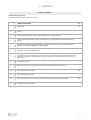
7 - START-UP
PRELIMINARY CHECKS
Checks with machine in OFF, before start-up .
For details refer to the various chapters in the manual.
√
Preliminary checks
Pag.
1
Safe access
2
Are the functional spaces being observed
3
Structure integrity
4
Unit in bubble level
14
5
Unit on vibration isolators
17
6
Return air filter available (size 200-650 necessary )
55
7
Presence of anti-intrusion grille against small animals or leaves (to be taken care of by the customer)
22
8
Air flow: correct return and supply (no bypass)
14
9
Completed aeraulic system
22
10
Insulation of supply conduits to room and air exhaust conduits
22
11
Presence of anti-vibration joints between the conduit and unit (e.g. canvas conduits)
22
12
Condensate drain with trap - sloping
21
13
Presence of electric heater (option) - installed correctly
65
14
Presence of humidifier (option - sizes 200-650 only) - installed correctly
69
15
Presence of electrostatic filter (option)
73
16
Visual check of oil / leak presence
17
Electrical connections provided by the customer
18
Earthing connection
19
Power supply cables separated by signal cables
15
24/27
30
7 - START-UP
START-UP SEQUENCE
Machine start-up operations.
For details refer to the various chapters in the manual.
√
Start-up sequence
1
Powered unit
2
Unit ON
3
Verify that the inlets/outlets in the room and any dampers in the conduits are open
4
Check the airflow (anemometer) by taking a reading directly on the external inlets and outlets (see table on
page 33)
5
Impossible to access the external inlets/outlets, check the airflows in the room using the following formula:
Airflow m3/h = Area (m2) x Speed (m/s) x 3600 seconds
6
Set the unit to winter mode ventilation only
7
Start the unit: when it reaches full power, with the compressor on verify that the evaporation pressure (status
51) exceeds 7 bar (values 200-600) and 1.8 bar (values 70-120), and that the temperature difference between
the external air (status 4) and the supply air (status 50) is at least 10°C in summer mode and at least 15°C in
winter mode.
8
Fans operation check
9
With the compressor on, verify that the unit's power supply voltage falls between 207-253 V
10
Fan configuration (size 200-650)
11
No anomalous vibrations check
12
Instruct the operator on how to switch the device on/off, change the set-point and clean the filter
13
Available machine documentation
Pag.
37
35
82
31
7 - START-UP
START-UP SEQUENCE
√
HEATER OPERATION CHECK (option)
1
set the unit to heating mode
2
temporarily set parameter 208=1
3
with the unit not powered, open the compressor's fuse holder (FU1 to sizes 200-650 / FUG to sizes 70-120)
4
start the unit and wait until the heaters begin treating the supply air
5
with the unit not powered, set parameter 208=0
6
close the compressor's fuse holder
√
HUMIDIFIER OPERATION CHECK (option, sizes 200-650 only)
1
set the unit to heating mode
2
through the ambient thermostat (parameter P05) or service keypad (parameter 30),
set the humidity set-point to 90%
3
check that the cylinder fills with water and starts boiling
4
a full cylinder combined with a very low current absorption value (with respect to the nominal value indicated
on the cylinder) and a delay in boiling do not imply any malfunctions, but indicate that the water is poorly
conductive and that the cylinder will take some time to reach full power
Pag.
37
26/27
Pag.
37
32
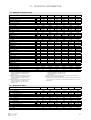
7 - START-UP
AIRFLOW TABLES
Airflows measured on the external inlets/outlets.
Example of conduits:
rectangular tube
(LxH)
circular tube
Ø mm
airflow
m3/h
speed medium
m/s
airflow
m3/h
speed medium
m/s
125
70
1,59
150
80
70
1,62
150
70
1,10
180
100
70
1,08
200
70
0,62
250
100
70
0,78
125
120
2,72
160
80
120
2,60
150
120
1,89
180
100
120
1,85
200
120
1,06
300
100
120
1,11
160
200
2,76
250
80
200
2,78
200
200
1,77
300
100
200
1,85
250
200
1,13
400
120
200
1,16
160
300
4,15
250
80
300
4,17
200
300
2,65
300
100
300
2,78
250
300
1,70
400
120
300
1,74
200
500
4,42
300
100
500
4,63
250
500
2,83
400
120
500
2,89
315
500
1,78
450
140
500
2,20
200
650
5,75
300
100
650
6,02
250
650
3,68
450
120
650
3,34
315
650
2,32
500
150
650
2,41
square tube
( L x H)
airflow
m3/h
speed medium
m/s
110
110
70
1,61
130
130
70
1,15
180
180
70
0,60
110
110
120
2,75
140
140
120
1,70
180
180
120
1,03
140
140
200
2,83
180
180
200
1,71
220
220
200
1,15
140
140
300
4,25
170
170
300
2,88
220
220
300
1,72
180
180
500
4,29
220
220
500
2,87
280
280
500
1,77
180
180
650
5,57
220
220
650
3,73
260
260
650
2,67
33
7 - START-UP
7.1 PRELIMINARY INFORMATION
General
• The indicated operations should be done by
qualified technician with specific training on the
product.
• The service centres shall perform by request the
start-up; the electrical, hydraulic connections and
the remaining work on the system are provided by
the installer.
• Agree upon the start-up date with the service centre
sufficiently in advance .
Before checking, please verify that :
• the unit should be installed properly and in
conformity with this manual.
• the electrical power supply line should be sectioned
at the beginning.
• the line sectioning device is open, locked and
equipped with the suitable warning signs.
• ensure no voltage is present .
After turning off the power, wait at least 5 minutes
before accessing to the electrical panel or any other
electrical component.
Before accessing check with a multimeter that there
are no residual stresses.
Refrigerant circuit
• Visually check the refrigerating circuit: the presence
of oil stains can mean leakage (caused, for
example, by transport, handling or other).
•
Use the pressure taps only if you need to load
or unload the refrigerant circuit.
Hydraulic circuit
If the humidifier is present:
• Before realizing the unit connection make sure that
the hydraulic system has been cleaned up and the
clearing water has been drained .
• Check that the water circuit has been charged and
pressurised .
• Check that the cut-off valves on the circuit are in
the "OPEN" position.
• Check that no air is present in the circuit, if
required, evacuate using the air bleeding valve
placed at the system's high points.
Electrical circuit
• Verify that the unit is connected to the ground
plant .
• Check tightening of the conductors: the vibrations
caused by handling and transport might cause
loosing .
• Feed the unit by closing the sectioning device, but
leave it on OFF
• Check the voltage and frequency net values which
must be within the limits:
230 / 1 / 50 +/- 10%
Check that the phases unbalancing must be lower than 2%
Example:
L1
L2
L3
388V
379V
377V
1)
388 + 379 + 377
=
381 (A)
3
2)
MAX - A = 388 – 381 = 7
3)
S=
7
x 100 =
1,83 OK
A
The operating out of the limits can cause irreversible
damages and makes decay the warranty.
Voltages
Check that the air and water temperatures are within
the operating limits.
With unit at steady state, i.e. in stable and close-towork conditions, check:
• supply voltage
• unit total absorption
• absorption of each electric load.
Remote controls / consents
Check that the used remote controls are wired and
enabled with the respective parameters :
•
•
•
•
•
•
ON-OFF
Summer-Winter
Silent
Ventilation
Electric resistances
Humidifier
Start-up report
Identifying the operating objective conditions is useful
to control the unit over time.
With unit at steady state, i.e. in stable and close-towork conditions, identify the following data :
•
•
•
•
Total voltages and absorptions with unit at full load
Absorptions of the different electric loads
(compressors, fans, pumps etc)
Temperatures and air flow of the different fluids
(water, air) both in input and in output from the unit
The measurements must be kept and made available during maintenance interventions.
34
7 - START-UP
7.2 FAN CONFIGURATION - CPAN-U 200 - 650
Depending on the ducting pressure drops are available
three configurations that can be set by the ambient
thermostat through the parameter modification.
The setting must be performed both for the exhaust fan
and for the supply fan.
See section 8.3
Fan parameters
P01
EXHAUST
P08
SUPPLY
= 1 Low pressure drop
~ 40 Pa
= 2 Medium pressure drop
~ 80 Pa
= 3 High pressure drop
~ 120 Pa
= 1 Low pressure drop
~ 40 Pa
= 2 Medium pressure drop
~ 80 Pa
= 3 High pressure drop
~ 120 Pa
On your keyboard:
P01 = SetUpFanRip = p232
P08 = SetUpFanMan = p233
7.3 CHECK OF THE AIR FLOW
After the fan configuration in function of the installation
pressure drop it is necessary to check the air flows.
•
Hold the On-Off button ( I ) for 5 seconds until the
unit start-up.
•
On the display is indicated the ambient setpoint.
•
Hold the ventilation button( C ), the unit is startedup in the ventilation only mode, check that the air
flows correspond to the nominal ones of the unit
(see the Technical Information section)
•
If necessary, change the outlet and exhaust fan
parameters as described above.
•
Hold the Ventilation button ( C ) to exit from the
Ventilation only mode
21.0
Ec
o
A
C
I
B
C
D
Cl
ea
n
I
ventilation
On - Off
35
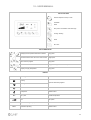
8 - CONTROL
KEYS FUNCTIONS
Ambient setpoint control up / down
Ventilation
Alarm
Eco (used in combination with other keys)
Cooling / Heating
Clean
ON / OFF
KEYS COMBINATION
It displays the temperature detected in ambient
Long press
It scrolls down the alarm list of one code at a time
Single press
+
Alarm reset in progress
Long press
+
Button lock / Button unlock
Long press It appears “- - -“ at each press
Display of supply temperature
Long press
+
DISPLAY
Icon
Meaning
Notes
Cooling
Symbols alternatively together
Heating
21.0
REMOTE
AUTO
Humidifier
Visible if active
Compressor
Visible if active
Set - point
Ambient temperature
Fan
Fan speed
Operation managed by supervisor
Visibile if Elfofresh² is connected to a supervisor
Automatic operating
Visible if active
36
8 - CONTROL
8.1 FIRST START-UP
•
Position the main switch of the installation on “On”.
•
The display is switched on in Off.
•
Hold the On-Off button ( I ) for 5 seconds until the
unit start-up.
•
The ambient setpoint is displayed.
•
Select the desired operating mode between heating
and cooling.
21.0
Cl
Ec
o
A
B
C
F
ea
n
G
I
Ventilation only
OFF
Cl
Ec
o
A
B
C
F
G
ea
•
Hold the Ventilation button ( C ) for 5 seconds until
the setpoint value is replaced with “- - -”.
•
To deactivate, hold the Ventilation button ( C ) for 5
seconds, until the setpoint value is displayed.
n
I
8.2 SHUTDOWN
Heating
•
Hold the Heating button ( G ) for 5 seconds until is
displayed the Heating symbol
•
Hold the On-Off button ( I ) for 5 seconds until the
unit shutdown.
•
Use the setpoint Control buttons ( A - B ) to set the
desired setpoint
•
“Off” is displayed
•
At the next starting, the unit is started-up in the last
set mode
Cooling
•
Hold the Cooling button ( F ) for 5 seconds until is
displayed the Cooling symbol.
•
Use the setpoint Control buttons ( A - B ) to set the
desired setpoint.
In each of the two modes is possible to activate the
function
OFF
Ec
o
Cl
ea
n
I
37
8 - CONTROL
8.3 PARAMETER MODIFICATION
8.4 OTHER CONFIGURATIONS
By the ambient thermostat is possible to set the unit
changing some parameters.
•
Position the main installation switch on “On”.
•
The display is switched on in Off.
•
Press the On-Off button ( I ) for 5 seconds until on
the display is visualized the ambient setpoint value.
•
Immediately press both buttons for the Setpoint
Control ( A - B ) until the code is visualized.
To adapt the unit operating to the installation needs, it
is possible to set the operating modifying some
parameters by the ambient thermostat.
Par.
Description
P02
manual or auto setpoint enabling (onsetman)
P03
manual or automatic mode change enabling
(onmodeman)
•
To switch to another parameter use the buttons for
the setpoint Control ( A - B ) .
P04
humidity setpoint in the Cool mode (seturcool)
•
Press the Eco button (E) to visualize the parameter
value.
P05
humidity setpoint in the Heat mode (seturheat)
Use the buttons for the setpoint Control ( A - B ) to
modify the value.
P06
outlet temperature setpoint in COOL mode
(setoutcool)
P07
outlet temperature setpoint in HEAT mode
(setoutheat)
Press both the buttons for the setpoint Control ( A B ) until the parameter code is visualized
P09
defines the range within which the user can change
the unit set point
If no action is performed, after 10 seconds the
thermostat will exit from the scheduling mode
P10
thermostat temperature probe offset
P11
thermostat humidity probe offset
P12
Clivet Bus thermostat address
•
•
Press the Eco button (E) to save.
To exit from the scheduling mode:
•
•
OFF
Ec
o
A
B
Cl
ea
n
I
E
P01
Ec
o
A
A
B
E
I
B
Cl
ea
n
E
I
Ambient setpoint control button up
Ambient setpoint control button down
Eco
On - Off
38
8 - CONTROL
8.5 MAIN FUNCTIONS
ELFOFresh2 treats fresh air: it is used for the air
filtration, humidification or dehumidification and the
right temperature is reached to guarantee always fresh
and clean air in the served rooms.
The temperature control is performed according to the
ambient temperature sent by ElfoControl2, or detected
by the HID-P1 thermostat or by the return probe
installed built-in.
Heating
In heating are managed the compressor, free-heating
(it uses the fresh air heat to heat the room),
resistances, humidifier.
Cooling
In cooling are managed the compressor and the freecooling (it uses the fresh air to cool the room).
Mode change
The change between cooling and heating can be:
AUTOMATIC: according to the outside temperature
MANUAL: by the thermostat button
For the automatic or manual change set the P03
ONModeMan parameter on the ambient thermostat.
Winter HR control
Only if is present the humidifier option.
The humidification is enabled only in heating.
The set point can be modified by thermostat with the
parameter p05 seturhe-at.
Silent
In this mode the fans are controlled with reduced
speeds.
The activation can be performed from digital input or
from supervisor.
The enabling is performed by parameter 224
SiletMode:
0=disabled; 1=from digital input; 2=from digital input or
supervisor.
The reduction of percentage is defined by the
parameter 225 (90% standard)
The silent mode can be activated only in heating .
Button lock / Button unlock
The long pressure of Clean and On-Off buttons, stop
all the button functions.
The lockout status is highlighted by characters “---“ at
each pressure of any button.
Set Point
There are two setpoint : cooling and heating.
The set can be modified in MANUAL or AUTOMATIC
mode.
Manual Set Point
In MANUAL mode it is possible to modify the setpoint
by thermostat with the buttons A and B (previous
page).
The two set are connected to avoid their overlapping.
If the cooling set is decreased, also the heating set is
automatically decreased.
If the heating set is increased, also the cooling set is
automatically decreased.
Automatic Set Point
The setpoint change according to the outside
temperature, depending on a curve set by parameters.
The heating setpoint is below the curve; the cooling
setpoint is above.
Ventilation
The unit operates as a fan, no control on the ambient
temperature.
39
8 - CONTROL
8.6 VENTILATION
AIR FLOW MODULATION
With an outdoor air temperature lower than -5°C, the
flow is reduced (A) to maintain the ambient inlet air
temperature (I) approximately equal to the internal
temperature ( 20°C) .
In this situation the need of ventilation is completely
satisfied.
NOMINAL FLOW
AIR flow
REDUCED FLOW IN WINTER
With an outdoor temperature included between -5°C
and +20°C, the fresh air flow remains constant (B).
The ambient inlet air temperature (II) increases at the
outdoor temperature increasing.
In this situation ELFOFresh2, in addition to satisfy the
needs of ventilation, satisfies in whole or in part the
heat request.
OUTDOOR AIR temp
With an outdoor temperature included between +20°C
and +24°C is effected a free-cooling increasing the inlet
fresh air flow and disabling the compressor (C).
The ambient inlet air temperature is equal to the
outdoor temperature (III).
REDUCED FLOW FOR DEHUMIDIFICATION
In order to effect more effectively the fresh air
dehumidification, ELFOFresh2 reduces the flow
modulating the fan speed (D), so it is possible to cool
the rooms by using the radiant panels and to effectively
dehumidify.
SUPPLY temp
FLOW
OUTDOOR AIR temp
STOPPING THE FANS
In certain circumstances, ventilation is stopped to prevent sudden temperature changes in the room.
When the ventilation is turned off, the compressor is turned off as well.
SUMMER
The ventilation is stopped if the temperature:
OUTSIDE
high, more than 40°C
or
AMBIENT
high, more than 35°C
or
SUPPLY
low, below 5°C
or
SUPPLY
high, more than ROOM SETPOINT value + 6°C
WINTER
The ventilation is stopped if the temperature:
OUTSIDE
low, below -15°C
or
AMBIENT
low, below 10°C
or
SUPPLY
low, below 8°C
or
SUPPLY
high, more than 45°C
40
8 - CONTROL
8.7 ALARMS
Whenever the unit is in alarm, on the thermostat
display is visualized the code of the alarm in progress.
The code will alternate at intervals of about 3 seconds
with the display of the ambient temperature.
In case of multiple alarms will be displayed what
occurred first.
To recognize the cause, refer to the ALARM table in
the “Technical Information” section.
Alarm visualization
•
To display all alarms in progress, press the Alarm
button ( D ).
•
To scroll down the alarm list press repeatedly the
Alarm button ( D ).
•
The display will return to normal visualization after 5
seconds from the last pressure on Alarms
Alarm reset
•
To reset the alarms press both the Eco ( E ).and the
Clean buttons ( H ).
•
Before resetting an alarm, identify and remove the
cause that generated it.
•
Repeated reset can lead to irreversible damages .
41
8 - CONTROL
ALARMS
Alarm
Description
Possible cause
E00
No communication between thermostat and unit
Check wiring between the thermostat and the unit board
Loose wiring, possible failure of the board or the thermostat following an
anomaly related to the power supply voltage
M
E01
Inlet temp. Probe fault
Check wiring.
Potential probe failure, replace it
A
E02
Outlet temp. Probe fault
Check wiring.
Potential probe failure, replace it
A
E03
Externe air temperature probe fault
Check wiring.
Potential probe failure, replace it
A
E05
Ambient humidity probe fault
Replace the thermostat.
A
E07
Supply humidity probe fault
Check wiring.
Potential probe failure, use a series tester to make sure that the generated
signal is within the range (4-20 mA).
Replace the probe
A
E10
Water temperature probe fault
Check wiring.
Potential probe failure, replace it.
A
E11
Fire alarm
If there is a fire sensor: check the sensor and the wiring.
If there is no fire sensor: check the input jumper.
M
E12
Outlet – inlet fan protection intervention
Check the supply voltage and absorption values.
M
E13
Compressor low pressure
SUMMER
insufficient supply air flow rate in ambient
- filters air dirty
- obstacles air distribution system
- supply fan fault
Cooling circuit anomaly - Contact a qualified technician.
A/M
WINTER
insufficient exhaust air flow rate
- filters air dirty
- return installation obstacles from ambient
- exhaust fan fault
- problems during defrost
E14
Compressor high pressure
WINTER
insufficient supply air flow rate in ambient
- filters air dirty
- obstacles air distribution system
- supply fan fault
M
SUMMER
insufficient exhaust air flow rate
- filters air dirty
- return installation obstacles from ambient
- exhaust fan fault
E15
Thermal compressor
Check the supply voltage, absorption values, refrigerant load.
M
E18
Humidifier alarm
problems related to the humidifier
M
E19
Outlet high temp. signaling
the temperature of the air supplied in the room is too high;
- the air is not compatible with the unit's operating limits
- insufficient supply air flow rate in ambient
- filters air dirty
- obstacles air distribution system
- supply fan fault
A
E20
Outlet 2 high temp. signaling
the temperature of the air supplied in the room is too high;
- the air is not compatible with the unit's operating limits
- insufficient supply air flow rate in ambient
- filters air dirty
- obstacles air distribution system
- supply fan fault
A/M
42
8 - CONTROL
ALARMS
Alarm
Description
Possible cause
E21
Outlet low temp. signaling
the temperature of the air supplied in the room is too low;
- the air is not compatible with the unit's operating limits
- insufficient supply air flow rate in ambient
- filters air dirty
- obstacles air distribution system
- supply fan fault
A
E22
Outlet 2 low temp. signaling
the temperature of the air supplied in the room is too low;
- the air is not compatible with the unit's operating limits
- insufficient supply air flow rate in ambient
- filters air dirty
- obstacles air distribution system
- supply fan fault
A/M
C23
Clogged filter signal
filters that need to be cleaned
A
E25
Ventilation block due to external low air
temperature
The external air is not compatible with the unit's operating limits and the
compressor cannot operate. Introducing air that is too cold with the
compressor off would mean cooling the room, something that should be
avoided.
The only solution is to wait for the outside environment to become warmer
A
E26
Ventilation block due to external high
temperature air
The external air is not compatible with the unit's operating limits and the
compressor cannot operate. Introducing air that is too warm with the
compressor off would mean warming up the room, something that should be
avoided.
The only solution is to wait for the outside environment to become cooler
A
E27
Ventilation block due to ambient low temperature
The air inside the house is not compatible with the unit's operating limits.
This might mean that there is no main heating system or that it is not running.
This is an air renewal unit with heat recovery and not a heating device: wait for
the room to reach the right temperature and then turn on the unit
A
E28
Ventilation block due to ambient high
temperature
The air inside the house is not compatible with the unit's operating limits.
This might mean that there is no main air-conditioning system or that it is not
running.
This is an air renewal unit with heat recovery and not an air-conditioning
device: wait for the room to reach the right temperature and then turn on the
unit
A
E29
Unit configuration error
internal anomaly
A
E31
Alarm of max supply temperature limit
the temperature of the air supplied in the room is too high;
poor air flow rate due to dirty air filters or features of the system
M
E33
Recovery compressor lockout for low
temperature ambient (heat mode)
The air inside the house is not compatible with the unit's operating limits.
This might mean that there is no main heating system or that it is not running.
This is an air renewal unit with heat recovery and not a heating device: wait for
the room to reach the right temperature and then turn on the unit
A
E34
Recovery compressor lockout for high ambient
air temperature (cool mode)
The air inside the house is not compatible with the unit's operating limits.
This might mean that there is no main air-conditioning system or that it is not
running.
This is an air renewal unit with heat recovery and not an air-conditioning
device: wait for the room to reach the right temperature and then turn on the
unit
A
C35
Humidifier on in antifreeze protection
see E04
A
Pressure transducer fault
Check wiring and values detected by the transducer.
Potential transducer failure, replace it
A
Fans off for fresh air temperature in Ventilation
Only mode
The unit is set to operate in ventilation-only mode (no active compressor), but
the external air is too warm / cold (depending on the mode).
Wait until the external air reaches again a temperature suitable for the unit's
operation
A
C/E36
C37
43
8 - CONTROL
ALARMS
Alarm
Description
Possible cause
C38
Modulating resi stance On with recovery circuit
Off
Air preheating, no anomaly
A
C39
Control of the supply title not satisfied
The unit operates regularly.
High supply air humidity: open windows, lots of people, etc.
A
E40
Inconsistency of the temperature differential
the temperature difference at the air inlet and outlet is not consistent with the
mode. For instance, in cooling mode the air supplied is warmer that the
external air. Among the various possible causes, the inversion valve of the
refrigerating circuit could be blocked
M
C65
Communication failure
as E00
A
The code C indicates the presence of an anomalous situation that does not prejudice the operation of the unit.
The E code indicates alarms that compromise the unit operating.
The passage from a code C to a code E occurs if the alarm switches from an automatic to a manual reset, this because the number of events per hour
that occurred exceeded the critical threshold.
A
B
the alarm automatically resets when the cause that set it off ends
the alarm manually resets when the cause that set it off ends and a keypad reset is executed
44
8 - CONTROL
8.8 SERVICE KEYPAD - OPTION
The service keypad allows the access to the unit parameters to perform the advanced settings or to display the
operating stata.
For the normal use of the keypad is not necessary the access to the unit parameters. The operations listed below are
required only for particular calibrations and configurations, they are therefore addressed only to qualified authorized
assistance centres.
A
B
R
C
D
Q
E
F
ST
A
TU
S
M
A
LA
R
P
O
G
H
M
I
L
SE
T
N
A
Signalling led of defrosting 1
I
On - Off
B
Signalling led of compressor 1
L
Set
C
Signalling led of defrosting 2
M
Arrow down
D
Signalling led of compressor 2
N
Index decrement
E
Stata menu
O
Arrow up
F
Alarms
P
Heating
G
Signalling led of the pump
Q
Cooling
H
Index increment
R
Led
ADVANCED CONFIGURATIONS
The access to the advanced configurations occurs on more levels on the basis of the password use.
Accessible parameters without password
•
Press the set button to enter in the scheduling
mode.
•
Select the parameter using the M and O arrows.
•
Modify the value by the + and - buttons.
•
To store, go to another parameter
•
Set to esc ( L ).
•
Pressing the set button ( L ), before passing to
another parameter, the modifications are not saved.
•
The full parameter list is available in the “Technical
Information” section
Par
Mnemonico
Description
1
OnModeMan
Operating mode manual selection
enabling
4
OnSetMan
Enables the manual ambient setpoint
30
SetURHeat
HR SetPoint in winter operating (2%)
97
SetURCool
HR SetPoint in summer operating (2%)
224 SilentMode
Enabling of the silence mode
45
8 - CONTROL
Parametres Mnemonico Description
Parameters protected by password
default
Press the Set button ( L ) to enter in the scheduling
mode.
P7
Text0
Outdoor temperature 0
15
P8
Text1
Outdoor temperature 1
18
•
Position on index 0 using the M and O arrows.
P9
Text2
Outdoor temperature 2
21
•
Insert the password 115 by the index Increment
( H ) and Decrement index buttons ( N ).
P10
Text3
Outdoor temperature 3
24
P11
Text4
Outdoor temperature 4
30
•
Modify the value by the index Increment ( H ) and
Decrement index buttons( N ).
P12
Set 00
value 0, setpoint 0
19
P13
Set 01
value 1, setpoint 1
21
•
To store, pass to another parameter pressing the
set button ( L ) before passing to another
parameter; the modifications are not saved.
P14
Set 02
value 2, setpoint 2
23
P15
Set 03
value 3, setpoint 3
25
P16
Set 04
value 4, setpoint 4
27
•
•
The possibility to access to the parameters by
password is automatically cancelled if any button is
pressed more than 2 minutes.
•
The modifications to the setting parameters that are
protected by password, can cause malfunctions.
4
In case of doubt contact an authorized assistance
centre.
3
2
The full parameter list is available in the “Technical
Information” section
1
0
H
SE
L
Index increasing
Set
Arrow down
Index decreasing
Arrow up
Press Status button ( E )
•
Select the status to display using the M and O
arrows
•
Press Status to esc ( E )
•
The full parameter list is available in the in the
“Technical Information” section”.
M
E
T
O
SE
Automatic setpoint
The setpoint change depending on the outside
temperature, according to a curve set by parameters.
A
LA
R
M
H
L
M
N
O
T
M
•
ST
A
TU
S
O
N
ST
A
TU
S
A
LA
R
M
OPERATING STATA
E Status
M Arrow down
O Arrow up
46
8 - CONTROL
8.9 UNIT STATA
NUMERICAL INDEX
DESCRIPTION
VALUE
001
Outlet actual SetPoint
°C
002
Inlet actual SetPoint
°C
003
Inlet temperature
°C
004
External temperature
°C
005
VHeat/CoolExt control component
%
006
VHeat/CoolAmb control component
%
007
VHeat/CoolRec control component
%
008
Compressor inverter control signal
009
Compressor operating mode (1= heat pump)
0÷1
%
010
Active title control status of the supply air
0÷1
011
Free-Cooling status
0÷1
012
Free-Heating status
0÷1
014
Outlet Fan control signal
015
Outlet Fan active Step number
016
Inlet Fan control signal
017
Inlet Fan active Step number
018
Water coil control signal / modulating preheating resistances
%
019
System water temperature
°C
020
Ambient UR probe
%
021
Outlet UR probe
023
On-Off humidifier status
0÷1
024
Humidifier control signal
%
027
Electrostatic filter control signal
%
028
Antifreeze Probe
°C
030
External damper status
0÷1
031
Unit clock
Hour
032
C1 operating hours
Hour
033
Not used
034
C1 starts
Int
035
Not used
Int
036
Keypad software
037
“keypad homologation year ”
2008
038
“keypad homologation month”
4
039
“keypad homologation day”
3
040
Base software
041
“base homologation year ”
2008
042
“base homologation month”
4
043
“base homologation day”
044
Modulation time of the water valve/heater control opening (calculation)
Sec
045
Correction time of the water valve/heater control opening (calculation)
Sec
046
Electrostatic filter on/off status
0÷1
048
Control signal of the modulating post-heating
%
050
Supply temperature
°C
051
Return pressure/exhaust air coil
Bar
052
Operative SetURCool (used in the SetXMan calculation)
053
Value of the setpoint for the control of the supply air title (SetXMan)
054
Value of the supply air title (XMan)
055
Value of the ambient air enthalpy (hAmb)
%
0÷1
%
0÷1
%
-
-
3
%
g/Kg
g/Kg
Kcal/Kg
47
8 - CONTROL
8.10 UNIT PARAMETERS FOR THE INSTALLER USE
N°
Description
Extended description
1
OnModeMan
Operating mode manual selection enabling
2
TempH2OHeat
Water temperature in heating
3
TempH2OCool
Water temperature in cooling
4
OnSetMan
Manual ambient setpoint enabling
6
DeadZone
Dead zone between winter and summer set
7
Text0
8
Text1
9
UM
default
Pass.*
1
0
°C
30
1
°C
20
1
1
0
°C
2
1
Setpoint compensation: external 0 temperature
°C
15
1
Setpoint compensation: external 1 temperature
°C
18
1
Text2
Setpoint compensation: external 2 temperature
°C
21
1
10
Text3
Setpoint compensation: external 3 temperature
°C
24
1
11
Text4
Setpoint compensation: external 4 temperature
°C
30
1
12
Set0
Setpoint compensation: value 0
°C
19
1
13
Set1
Setpoint compensation: value 1
°C
21
1
14
Set2
Setpoint compensation: value 2
°C
23
1
15
Set3
Setpoint compensation: value 3
°C
25
1
16
Set4
Setpoint compensation: value 4
°C
27
1
17
ExtRecManager
Enables the recovery compressor management at supervisor charge
0
1
18
BandPR
Proportional band
°C
2
1
19
DeltaHeatAmb
Dead zone (VheatAmb)
°C
3
1
20
BandHeatRec
Proportional band (VheatExt)
°C
10
1
21
DeltaHeatRec
Dead zone (VheatExt)
°C
22
RecInteg
Water coil operating enabling only in integration
24
LimTextHeat
External temp. limit for the compressor operating in heating
25
TextCompOn
External temperature limit below which the compressor is always on
26
SetOutHeat
27
28
3
1
1
1
°C
-15
1
°C
10
1
Outlet SetPoint in heating
°C
-3
1
DeltaSetOutHeat
Setpoint variation range in Heat outlet
°C
20
1
BandOutHeat
Water coil modulation band in heating
°C
2
1
30
SetURHeat
UR SetPoint in heating
%
55
0
31
BandURHeat
UR humidity control band in winter ambient
%
10
1
32
SetUROut
Outlet limit humidity in heating
%
90
1
33
BandUROut
Outlet limit humidity control band
%
10
1
34
MaxOut
Humidifier control signal max. value
%
100
1
35
LimTextCool
Compressor external temperature limit in cooling
°C
40
1
36
BandCoolRec
Proportional band (VCoolExt)
°C
5
1
37
DeltaCoolRec
Dead zone (VCoolExt)
°C
3
1
38
DeltaCoolAmb
Dead zone (VCoolAmb)
°C
5
1
40
SetOutCool
Outlet SetPoint in cooling
°C
-2
1
41
DeltaSetOutCool
Setpoint variation range in Cool outlet
°C
5
1
42
BandOutCool
Water coil modulation band in cooling
°C
2
1
44
LimOutDC
Outlet temperature limit during the dehumidification
°C
23
1
45
BandLimOutDC
Outlet temperature limit control band during the dehumidification
°C
2
1
46
TimeStart
Fan starting time
sec
60
1
47
TimeStop
Fan stopping time
sec
60
1
48
TextStopFanHeat
Ventilation stop external temp. in Heat
°C
-15
1
49
TambStopFanHeat
Ventilation stop ambient temp. in Heat
°C
10
1
50
TextStopFanCool
Ventilation stop external temp. in Cool
°C
38
1
51
TambStopFanCool
Ventilation stop ambient temp. in Cool
°C
30
1
54
TimeCycle
Time between ventilation stop and start
sec
1800
1
88
TimeThrow
Permanence max. time of the outlet temperature more than the allowed limits
sec
600
1
89
MaxFiltri
Filter max. control signal value
%
100
1
90
Minfiltri
Filter min. control signal value
%
20
1
92
SetAlarmFreeze
SetPoint for water coil antifreeze alarm
°C
4
1
93
DeltaAlarmFreeze
Differential for the water coil antifreeze alarm reset
°C
2
1
94
Tstarting
Min. interval between start/stop of two compressors
sec
10
1
96
FanPFcorr
PWM fan power factor correction
1=500ns
3800
1
97
SetURCool
UR SetPoint in cooling
%
60
0
99
TimeByPassFiltri
Clogged filter alarm Bypass time
sec
30
1
100
SetAlarmOverheating
Setpoint for water coil overtemperature
°C
90
1
48
8 - CONTROL
101
102
DeltaAlarmOverheating
DeltaMinH2OHeat
Differential for water coil overtemperature alarm reset
Difference of water coil air temperature during heating with water at TH2OminHeat
°C
°C
2
10
1
1
103
DeltaMaxH2OHeat
Difference of water coil air temperature during heating with water at TH2OMaxHeat
°C
32
1
105
TH2OMinHeat
Coil hot water temperature that provides the DeltaMinH2OHeat
°C
38
1
106
TH2OMaxHeat
Coil hot water temperature that provides the DeltaMaxH2OHeat
°C
70
1
107
DeltaMinH2OCool
Difference of water coil air temperature during cooling with water at TH2OMinCool
°C
10
1
108
DeltaMaxH2OCool
Difference of water coil air temperature during cooling with water at TH2OMaxCool
°C
32
1
109
TH2OMinCool
Coil hot water temperature that provides the DeltaMinH2OCool
°C
5
1
110
TH2OMaxCool
Coil hot water temperature that provides the DeltaMaxH2OCool
°C
12
1
111
TimeOpenValve
Water coil opening time
sec
140
1
112
TimeCorrection
Water coil opening correction time
sec
40
1
119
LimTambHeat
Compressor operating limit in heating for ambient temperature
°C
16
1
120
LimTambCool
Compressor operating limit in cooling for ambient temperature
°C
30
1
126
MaxVarDeltaBatt
Max DeltaBatteria variation beyond which is performed the water valve modulation reset
0: it excludes the reset on the DeltaBatteria variation
°C
4
1
127
MaxVarSetOut
Max SetMandata variation beyond which is performed the water valve modulation reset
0: it excludes the reset on the SetMandata variation
°C
2
1
128
MinApValvH2O
Min. opening of the handling water coil valve (phisical threshold to have the flow)
2
1
129
RiduzDeltaBattH2O
Reduction coefficient to the coil delta in the valve modulation of initial opening
%
70
1
131
OffSetTin
Inlet probe offset
°C
0
1
132
OffSetTout
Outlet probe offset
°C
0
1
133
OffSetText
External temperature probe offset
°C
0
1
135
OffSetTfreeze
Antifreeze probe offset
°C
0
1
137
OffSetTH2O
system water probe offset
°C
0
1
139
OffSetURProbe
Ambient humidity probe offset
%
0
1
141
OffSetURProbeThrow
Outlet humidity probe offset
%
0
1
149
MinProbePress
Pressure value corresponding to 4mA of the return pressure transducer /exhaust air coil
bar
0
1
150
MaxProbePress
Full scale value of the return pressure transducer/exhaust air coil
bar
50
1
151
OffsetProbePress
return pressure transducer offset/exhaust coil
bar
0
1
165
MODBusAddress
ModBus serial address
55
1
166
Baud Rate
Baud Rate (0=4800 / 1=9600)
0
1
167
Parity
Parity (0=no / 1=si)
0
1
168
CANaddressNode
CANOPEN board address
1
1
180
TimeOnURfreeze
Humidifier activation time in antifreeze
min
5
1
181
TimeOffURfreeze
Humidifier off wait time in antifreeze
min
60
1
182
PotURfreeze
Modulating output level of the humidifier in antifreeze
%
20
1
183
hAmbStopComp
Ambient enthalpy setpoint that leads to compressor stop
g/kg
7,2
1
184
DeltahAmb
Ambient enthalpy delta for compressor enabling
g/kg
0,7
1
185
MaxRip_0
Max. value of the return fan control (with SetUpFanRip= 0)
%
100
1
186
MinRip_0
Min. value of the return fan control (with SetUpFanRip= 0)
%
20
1
187
MaxMan_0
Max. value of the supply fan control (with SetUpFanMan= 0)
%
100
1
188
MinMan_0
Min. value of the supply fan control (with SetUpFanMan= 0)
%
20
1
189
NomHeatRip_0
Nominal value of the return fan control in Heat (with SetUpFanRip= 0)
%
50
1
190
NomCoolRip_0
Nominal value of the return fan control in Cool (with SetUpFanRip= 0)
%
50
1
191
NomHeatMan_0
Nominal value of the supply fan control in Heat (with SetUpFanMan= 0)
%
50
1
192
NomCoolMan_0
Nominal value of the supply fan control in Cool (with SetUpFanMan= 0)
%
50
1
198
MinTThrowHeat
Min. supply temperature in Heat
°C
10
1
199
DeltaTThrowHeat
Differential for the MinTThrowHeat calculation
°C
2
1
200
MaxTThrowHeat
Keypad address
°C
45
1
201
DeltaTThrowCool
Differential for the MaxTThrowCool calculation
°C
5
1
202
MinTThrowCool
Min. supply temperature in Cool
°C
10
1
204
MinSetTHeat
Min. ambient set that can be set manually in Heat
°C
17
1
205
MaxSetTHeat
Max. ambient set that can be set manually in Heat
°C
24
1
206
MinSetTCool
Min. ambient set that can be set manually in Cool
°C
24
1
207
MaxSetTCool
Max. ambient set that can be set manually in Cool
°C
28
1
208
HeatMode
Operating mode in Heat (0=Efficiency, 1=Comfort)
0
1
220
EnBatteria
Coil enabling (0=no coil, 1=extH2O coil, 2=preheating resistances)
0
1
49
8 - CONTROL
224
SilentMode
Enabling of the silence mode:0 disabled,1 from digital input (ID4),2 digital input /
supervisor
0
0
225
PercSilent
Percentage respect to the nominal of the reference signals in silence mode
%
90
1
226
LimNewAirCool
Inhibition threshold of Ventilation Only in Cool
°C
35
1
227
LimNewAirHeat
Inhibition threshold of Ventilation Only in Heat
°C
13
1
228
BandMan
Proportional band of the supply flow rate control in Cool
°C
4
1
232
SetUpFanRip
Selection of the setting setup of the fan parameters in Return
0
0
233
SetUpFanMan
Selection of the setting setup of the fan parameters in Supply
0
0
234
MaxRip_1
Max. value of the return fan control signal (with SetUpFanRip= 1)
%
55
1
235
MinRip_1
Min. value of the return fan control signal (with SetUpFanRip= 1)
%
40
1
236
MaxMan_1
Max. value of the supply fan control signal (with SetUpFanMan= 1)
%
55
1
237
MinMan_1
Min. value of the supply fan control signal (with SetUpFanMan= 1)
%
40
1
238
NomHeatRip_1
Nominal value of the return fan control signal in Heat (with SetUpFanRip= 1)
%
46
1
239
NomCoolRip_1
Nominal value of the return fan control signal in Cool(with SetUpFanRip= 1)
%
55
1
240
NomHeatMan_1
Nominal value of the supply fan control signal in Heat (with SetUpFanMan= 1)
%
48
1
241
NomCoolMan_1
Nominal value of the supply fan control signal in Cool(with SetUpFanMan= 1)
%
48
1
242
MaxRip_2
Max. signal of the return fan control signal (with SetUpFanRip= 2)
%
60
1
243
MinRip_2
Min. signal of the return fan control signal (with SetUpFanRip= 2)
%
45
1
244
MaxMan_2
Max. signal of the supply fan control signal (with SetUpFanMan= 2
%
60
1
245
MinMan_2
Min. signal of the supply fan control signal (with SetUpFanMan= 2)
%
45
1
246
NomHeatRip_2
Nominal value of the return fan control signal in Heat (with SetUpFanRip= 2)
%
51
1
247
NomCoolRip_2
Nominal value of the return fan control signal in Cool(with SetUpFanRip= 2)
%
60
1
248
NomHeatMan_2
Nominal value of the supply fan control signal in Heat (with SetUpFanMan= 2)
%
53
1
249
NomCoolMan_2
Nominal value of the supply fan control signal in Cool(with SetUpFanMan= 2)
%
53
1
250
MaxRip_3
Max. value of the return fan control signal (with SetUpFanRip= 3)
%
65
1
251
MinRip_3
Min. value of the return fan control signal (with SetUpFanRip= 3)
%
50
1
252
MaxMan_3
Max. value of the supply fan control signal (with SetUpFanMan= 3)
%
65
1
253
MinMan_3
Min. value of the supply fan control signal (with SetUpFanMan= 3)
%
50
1
254
NomHeatRip_3
Nominal value of the return fan control signal in Heat (with SetUpFanRip= 3)
%
56
1
255
NomCoolRip_3
Nominal value of the return fan control signal in Cool (with SetUpFanRip= 3)
%
65
1
256
NomHeatMan_3
Nominal value of the supply fan control signal in Heat (with SetUpFanMan= 3)
%
58
1
257
NomCoolMan_3
Nominal value of the supply fan control signal in Cool (with SetUpFanMan= 3)
%
58
1
258
TimeScanDeltaTManExt
% Fan at start
min
15
1
259
MaxNDeltaTManExt
% Fan at start
num
3
1
600
AddTast
Keypad address
7
1
* Pass
=0
Accessible without password
Pass
=1
Access for Installers, with password
50
9 - MAINTENANCE
9.1 GENERAL
9.4 PUT AT REST
Maintenance must be done by authorized centres or by
qualified personnel
The maintenance allows to:
If a long period of inactivity is foreseen:
•
put the unit in OFF
•
wait a few minutes to allow all the actuators to
reach the rest position
Turn off the power in order to avoid electrical risks
or damages by lightning strikes
•
maintain the unit efficiency
•
reduce the deterioration speed to whom every
equipment is subject over time
•
•
assemble information and data to understand the
state of the unit efficiency and avoid possible
damages
•
Before checking, please verify the following:
•
the electrical power supply line should be isolated
at the beginning
•
the unit isolator is open, locked and equipped with
the suitable warning
•
make sure no tension is present
After turning off the power, wait at least 5 minutes
before accessing to the electrical panel or any other
electrical component.
Before accessing check with a multimeter that there
are no residual stresses.
9.2 INSPECTIONS FREQUENCY
Perform an inspection every 6 months minimum.
The frequency, however, depends on the use.
In the event of frequent use it is recommended to plan
inspections at close intervals:
•
•
frequent use (continuous or very intermittent use,
near the operating limits, etc)
avoid the risk of frost (empty or add glycol to the
parts of the system exposed to temperatures below
zero, maintain powered any anti-freeze
resistances )
It’s recommended that the starting-up after the
stopping period is performed by a qualified technician,
especially after seasonal stops or seasonal switch.
When restarting, refer to what is indicated in the
START-UP section.
Schedule technical assistance in advance to avoid
hitches and to guarantee that the system can be used
when required.
9.5 STRUCTURE
Check the condition of the structure parts .
Paint so as to eliminate or reduce oxidation where
needed.
Check that the paneling is correctly fastened. Poor
fastening may give rise to malfunctions and abnormal
noise and vibration .
9.6 COIL
critical use (service necessary).
The accidental contact with the fins of the exchanger
may cause small cuts: use protective gloves.
9.3 UNIT BOOKLET
It’s advisable to create a unit booklet to take notes of
the unit interventions.
In this way it will be easier to adequately note the
various interventions and aid any troubleshooting.
Report on the booklet:
•
data
•
type of intervention effected
•
intervention description
•
carried out measures etc.
The finned surfaces of the coils and especially the
drain pans are the places where micro-organisms and
moulds most easily flourish.
It is therefore very important to clean regularly with
suitable detergents and in case disinfect with
appropriate products.
9.7 CONDENSATE DISCHARGE
Dust and deposits could cause obstructions .
In addition in the pan can proliferate microorganisms
and moulds.
It is very important to provide a periodic cleaning with
appropriate detergents and in case a disinfection with
sanitizing products.
After cleaning pour water into the pan to ensure a
regular flow.
51
9 - MAINTENANCE
9.8 AIR FILTERS
CPAN-U 70 - 120
It is very important for the air treatment coil to be able to offer
maximum thermal exchange. Therefore, the unit must always
operate with the filters installed and clean.
Cleaning and replacement of filters are very important in terms
A
of health and hygiene.
The operating with clogged filters leads to a reduction of the
air flow, leading to malfunctions and unit shutdowns.
How often the filters need to be checked depends on the
quality of outdoor air, unit operating hours, dust and number
B
of persons in the rooms.
Approximately, cleaning should ideally take place between
weekly and monthly. It is advisable to start with frequent
checks, and to adjust the frequency based on how much dirt
is discovered.
Old filters, washing residuals and residual parts must be
CPAN-U 200 - 650
disposed of, according to the law in force .
Access to the filters
The access to the filters is possible in two positions :
CPAN-U 70-120
A - Superior access
B - Lower access
C
CPAN-U 200-650
C - Lateral access
D
D - Lower access
To access to the filters:
•
•
Remove the closing panels
•
Proceed in reverse.
Carefully extract the filter so that no dust reaches the
parts below
To reposition the filter:
E
Cleaning of the pleated filter
•
Wash the filtering mattress in warm water with a common
detergent.
•
Carefully rinse it under water while preventing to pour
water in the room.
•
Dry the filter .
Lateral access:
To easily remove the filter it is possible to remove the
handle ( E )
52
9 - MAINTENANCE
9.9 ELECTROSTATIC FILTER - OPTION
Access to the filter:
•
•
Switch off the unit.
•
•
Extract the filter ( A ).
Extract the metal mesh prefilter ( D ) only CPAN-U 200650
Disconnect the quick connector ( C ).
The filter status is signalled by the green led on the higher
part of the filter.
on
→ Correct operating
flashing
→ Stopped filter
off
→ Check the electrical connections
A
B
C
D
Electrostatic filter
Signalling green led
Quick connector
Metal mesh prefinte (only CPAN-U 200-650)
Cleaning of the electrostatic filter
MATERIALS NECESSARY FOR MAINTENANCE
1. Acid detergent B01212 (code CLIVET C6460316);
2. plastic or steel tank (750x750x310 mm) with settling bottom
3. Protective gloves and goggles;
4. Graduated jug;
5. Pump for manual or pneumatic spraying.
Do not use aluminum tanks or galvanized.
Foresee a stainless steel frame that keeps the filters lifted
from the tank base to have a settling bottom for the muds.
1. Position the filter to be washed on a support to facilitate
work.
2. Prepare a tank with a solution of B01212 detergent and
water at 1÷20.
3. Immerse the filter in this solution
4. Ensure the solution covers the entire filter
5. Immerse it for about 5-7 minutes. A slight chemical
reaction is noticed within 2÷3 minutes with the
development of foam indicating the occurred elimination of
residues.
6. Rinse the filter with a jet of water or using a low-pressure
water jet machine.
7. Leave the electrostatic cells to dry in a hot room or directly
in the sun for a few hours.
Keep the cells lifted from the ground using two metal or
wooden laths.
8. Check the ionisation wires before remounting the filter.
The cleaner can be used to clean about 20 filters.
Can be recovered and placed in plastic containers closed; the
air oxidizes the cleaner and reduces its effectiveness
IONISATION WIRES
The impurities can determine oxidation or scaling on the
wires, which can be removed using a cloth soaked in alcohol
or an abrasive scourer with very fine grain.
Due to the high voltage powering them, the ionisation wires
are subject to wear.
To foresee a yearly replacement OF ALL WIRES avoids
unexpected breaks.
In case of break: :
1. remove all wire pieces present in the cell and remove the
springs stretching the wire;
2. hook the spring to the wire eyelet;
3. grip the ionisation wire with curved beaks pliers;
4. hook the top of the spring with the open eyelet to the wire
stretcher rod of the electrostatic cell;
5. keeping the ionisation wire stretched, with the other hand
hook it to the other wire stretching rod, always by means
of the curved beaks pliers.
750
750
310
H2O
A
B
C
A
B
C
Curved pincer
Spring
Wire
53
9 - MAINTENANCE
9.10 RETURN / SUPPLY AMBIENT FILTER
CPAN-U 70 - 120
The ambient filter installation is possible in 2 positions:
A - from the top (floor units)
B - from the bottom (ceiling units)
A
B
To clean the filter:
• Unscrew the 2 screws of the locking filter
• Clean the filter in tepid water with common
detergent.
•
Rinse thoroughly in running water to avoid spillage
into the served area.
•
Dry the filter.
54
9 - MAINTENANCE
9.11 RETURN AMBIENT FILTER - OPTION
CPAN-U 200 - 650
Lateral ceiling installation not allowed.
The ambient filter installation is possible in 3 positions:
A - from the top (floor units)
B - from the bottom (ceiling units)
C - lateral (floor units)
A
Minimum space for filter extraction.
B
Min. 350 mm
C
Unscrew the front screws.
Remove the existing collar.
Installation not permette.
Install the filter holder.
55
9 - MAINTENANCE
Insert the filter.
Close the filter.
To clean the filter:
•
Unscrew the 2 screws of the locking filter
•
Clean the filter in tepid water with common detergent.
•
Rinse thoroughly in running water to avoid spillage
into the served area.
•
Dry the filter.
56
9 - MAINTENANCE
9.12 FANS
CPAN-U 200 - 650
CPAN-U 70 - 120
The fans can be removed from above.
•
Remove the roof
•
Unscrew the 4 front screws.
•
Disconnect the quick connector.
•
Extract the fan
The fans can be removed from above and from below.
•
Remove the roof or the lower panel.
•
Unscrew the 4 front screws.
•
Disconnect the quick connector.
•
Extract the fan
9.13 HUMIDIFIER - CPAN-U 200 - 650
The humidifier and the cylinder contain live electrical components and hot surfaces.
During operation, the steam production cylinder reaches high temperatures!
Maintenance must be performed after the cylinder has cooled. Use protective gloves.
The cylinder must be replaced periodically.
This operation is necessary when lime incrustations build up on the inside such that sufficient current passage does not
occur.
How frequently this needs to be done depends on the water supply. The harder the water, the more often the cylinder
will need to be replaced.
See water tables on page 70
After prolonged use or use with very hard water, the solid deposits on the electrodes may increase in size until they
adhere to the inner wall of the cylinder.
With especially conductive deposits, the plastic may heat so much that it melts, resulting in water leakage.
In case of leaks, power off the unit before touching the cylinder, because electrical current may be flowing through the
water.
PERIODIC CHECKS
Do not use detergents or solvents to clean plastic components.
To remove incrustations, wash with a 20% solution of vinegar or acetic acid, and then rinse with water .
Every 15 days
Cylinder
after not more than 300 hours of service check of operation,
general condition, lack of leaks
Every 3 months
Cylinder
after not more than 1000 hours of service check of operation,
general condition, lack of leaks, any replacement required
Cylinder
after not more than 2500 hours of service (disposable cylinders) replacement
Filling solenoid valve
disconnect the electrical power supply, remove the valve, and clean
the filter
Filling solenoid valve
disconnect the electrical power supply, remove the bobbin,
disassemble the valve body, remove any impurities and rinse
Supply pan , ducts
check that they are free and without impurities
Cylinder
after not more than 10000 hours of service (for inspectable
cylinders) - replacement
Every year
Every 5 years
57
9 - MAINTENANCE
Before putting it back in place:
Drainage of humidifier cylinder
The cylinder must be drained in these situations:
•
cleaning of the cylinder
•
emptying of the cylinder to prevent formation of ice
• replacement of cylinder
•
The filter body does not need to be replaced.
Wash it with water and place it on the new
cylinder, using the new gasket that comes with it.
•
Check the gasket for the seal between the cylinder
and the drain group.
•
Put the cylinder back in place by repeating the
operations in reverse
On the electronic card that controls the humidifier:
•
to activate drainage move the jumper to the terminals
GND and DR
•
to resume operation of the humidifier, return the jumper
to the terminals GND – ON
Refer to the electrical diagram of the unit
A
ON
GND
B
P
DR
A
B
P
ON
GND
DR
P
Humidifier ON
Drainage ON
Jumper
Replacement of the cylinder
To remove the cylinder:
•
Completely drain the water.
•
Cut power to the humidifier using the unit isolator
switch.
•
Remove the steam tube from the cylinder.
•
Detach the electrical connections of the electrodes
and remove the plugs from the high-level
electrodes.
•
Unscrew the ring nut to remove the nozzle and the
filter (when the filter is outside the cylinder)
•
Lift the cylinder to extract it
58
9 - MAINTENANCE
9.14 RECOMMENDED PERIODICAL CHECKS SHEET
Checks carried out on…………………….......by……………………………...………….company…..............…………………………………………….
√
intervention frequency (months)
□
presence corrosion
□
panel fixing
□
fans fixing
□
coil cleaning
□
bowl cleaning + sanitisation
□
outflow test
□
air filters cleaning/inspection
□
air flow rate measurement
□
channelling: anti-vibration devices and fastenings check
□
power supply cable isolation and fastening check
□
earth cable check
□
electric control board cleaning
□
power remote controls state
□
clamps closure, cables isolation integrity
□
phases unbalancing and power supply voltage (vacuum and loaded)
□
absorption of the individual electric loads
□
compressors carter heaters test
□
leaks control *
□
cooling circuit work parameters detection
□
four-way valve exchange check
□
protective equipment test: safety valves, pressure switches, thermostats, flow meters, etc.
□
protective equipment test: setpoint, climatic compensations, power slicing, air flow rate variations
□
control devices test: alarms signal, thermometers, probes, pressure gauges, etc.
□
electrical heaters check - option
□
water coil check
3
6
12
Notes/interventions recommended to Owner
*European regulation 303/2008:
Refer to the local implemented standards; in synthesis and for merely indicative purposes, the regulation prescribes the following.
Companies and technicians carrying out installation, maintenance/repair interventions, leaks check and recovery must be CERTIFIED as
foreseen by the local standards.
The leaks check must be carried out on a yearly basis
59
10 - TECHNICAL INFORMATION
10.1 DIMENSIONS
SIZE
70
120
200
300
500
650
Dimensions nr.
Length
Depth
Height
1
800
690
266
1
800
690
266
2
922
704
364
2
922
704
364
3
1158
792
423
3
1158
792
423
mm
mm
mm
DIMENSIONS 1
800
27
133
464
M
202
R
590
636
2
690
1
46
3
4
27
AE
22
ES
755
484
O
8
133
15
0
** 20
182
22
** 500
5
6
** (A) 20
20
266
107
** 20
7
** 300
60
AE
** MINIMUM SPACE FOR MAINTENANCE
A(20) : only for ceiling installation
** 500
ES
** 20
R
** 300
M
(1) REMOVABLE PANEL FROM LOWER ACCESS OF THE EXHAUST AIR FILTER
(2) REMOVABLE PANEL FROM LOWER ACCESS OF THE ELECTRICAL PANEL
(3) REMOVABLE PANEL FROM LOWER ACCESS OF THE HANDLING FILTER AIR
(4) REMOVABLE PANEL FROM LOWER ACCESS OF THE FILTER AIR INTAKE
(5) REMOVABLE PANEL FROM SIDE ACCESS OF THE ELECTRICAL PANEL
(6) CONDENSATE DISCHARGE DUCT
(7) REMOVABLE PANEL FROM CLIENT TERMINAL BLOCK ACCESS
(8) FIXING POINTS
(AE) FRESH AIR INTAKE
(ES) AIR EXHAUST
(M) AMBIENT AIR DISTRIBUTION
(R) AMBIENT AIR INTAKE
60
10 - TECHNICAL INFORMATION
DIMENSIONS 2
** min:
a) - ceiling installation, filter access from below, remote
electrical control board at a distance of at least 200 mm
b) -ceiling installation, filter access from below, non-remote
electrical control board at a distance of at least 700 mm
c) -floor installation, lateral filter access, remote electrical
control board at a distance of at least 400 mm
d) -floor installation, lateral filter access, non-remote electrical
control board at a distance of at least 700 mm
** MINIMUM SPACE FOR MAINTENANCE
20mm : only for ceiling installation
(1) REMOVABLE PANEL FOR ACCESS TO THE COMPONENTS OF HANDLING SECTION
(2) REMOVABLE PANEL FOR ACCESS TO THE COMPONENTS OF THE RECOVERY
SECTION
(3) REMOVABLE PANEL FOR LOWER ACCESS TO THE AIR FILTER
(4) ELECTRICAL PANEL
(5) FIXING POINTS
(6) POWER INPUT
(7) CONDENSATE DISCHARGE DUCT
(8) REMOVABLE PANEL FOR LOWER ACCESS TO THE AIR FILTER
(AE) FRESH AIR INTAKE
(ES) AIR EXHAUST
(M) AMBIENT AIR DISTRIBUTION
(R) AMBIENT AIR INTAKE
61
10 - TECHNICAL INFORMATION
DIMENSIONS 3
** min:
a) - ceiling installation, filter access from below, remote
electrical control board at a distance of at least 200 mm
b) -ceiling installation, filter access from below, non-remote
electrical control board at a distance of at least 700 mm
c) -floor installation, lateral filter access, remote electrical
control board at a distance of at least 400 mm
d) -floor installation, lateral filter access, non-remote electrical
control board at a distance of at least 700 mm
** MINIMUM SPACE FOR MAINTENANCE
20mm : only for ceiling installation
(1) REMOVABLE PANEL FOR ACCESS TO THE COMPONENTS OF HANDLING SECTION
(2) REMOVABLE PANEL FOR ACCESS TO THE COMPONENTS OF THE RECOVERY
SECTION
(3) REMOVABLE PANEL FOR LOWER ACCESS TO THE AIR FILTER
(4) ELECTRICAL PANEL
(5) FIXING POINTS
(6) POWER INPUT
(7) CONDENSATE DISCHARGE DUCT
(8) REMOVABLE PANEL FOR LOWER ACCESS TO THE AIR FILTER
(AE) FRESH AIR INTAKE
(ES) AIR EXHAUST
(M) AMBIENT AIR DISTRIBUTION
(R) AMBIENT AIR INTAKE
WEIGHT DISTRIBUTION
SIZE
70
Dimensional nr.
120
200
300
500
650
1
1
2
2
3
3
Shipping weight
kg
40
43
85
90
115
120
Operating weight
kg
37
40
70
75
95
100
62
10 - TECHNICAL INFORMATION
10.2 GENERAL TECHNICAL DATA
SIZES
COOLING AE 30°C
Cooling capacity
Compressor power input
Total power input
EER (EN 14511-2011)
COOLING AE 35°C
Cooling capacity
Compressor power input
Total power input
EER (EN 14511-2011)
HEATING AE 7°C
Heat output
Compressor power input
Total power input
COP (EN 14511-2011)
HEATING AE –5°C
Heat output
Compressor power input
Total power input
COP (EN 14511-2011)
COMPRESOR
Type of compressors
No. of Compressors
Type of refrigerant
Refrigerant charge
FANS
Type of fans
Number of fans
Air flow
Absorbed capacity by fans
Available head nominal
Max outside static pressure
CONNECTIONS
Condensate discharge
POWER SUPPLY
Standard power supply
NOISE LEVELS
Sound pressure level (1m)
70
120
200
300
500
650
1
1
1
1
kW
kW
kW
0,429
0,164
0,189
2,27
0,813
0,279
0,315
2,58
1,57
0,498
0,542
2,90
2,10
0,640
0,700
3,00
3,01
0,916
1,04
2,91
4,03
1,29
1,48
2,72
2
2
2
2
kW
kW
kW
0,446
0,174
0,199
2,24
0,846
0,297
0,333
2,54
1,63
0,523
0,567
2,87
2,17
0,674
0,734
2,96
3,13
0,976
1,096
2,86
4,23
1,33
1,519
2,78
3
3
3
3
kW
kW
kW
0,517
0,139
0,153
3,38
0,984
0,235
0,252
3,90
1,81
0,401
0,441
4,10
2,33
0,541
0,593
3,93
3,58
0,748
0,838
4,27
5,00
1,12
1,27
3,94
4
4
4
4
kW
kW
kW
0,517
0,110
0,124
4,17
0,971
0,188
0,205
4,74
1,86
0,320
0,360
5,17
2,35
0,379
0,431
5,45
3,74
0,582
0,672
5,57
5,10
0,846
0,996
5,12
ROT
1
R134a
0,32
ROT
1
R134a
0,21
ROT
1
R410A
0,80
ROT
1
R410A
0,75
ROT
1
R410A
1,00
ROT
1
R410A
1,45
CFG
2
70
0,014
40
120
CFG
2
120
0,017
40
120
CFG
2
200
0,040
40
120
CFG
2
300
0,052
40
120
CFG
2
480
0,090
40
120
CFG
2
650
0,150
40
120
16
16
26
26
26
26
230/1/50
230/1/50
230/1/50
230/1/50
230/1/50
230/1/50
38
39
41
44
46
Nr
Kg
Nr
mc/h
5 kW
Pa
Pa
V
6 dB(A)
37
(1) AE 30°C: data referred to the following conditions:
− Outdoor air temperature: 30°C BS/ 22.0°C BU
− Internal air temperature: 27°C BS/ 19°C BU
− nominal air flow
(2) AE 35°C : data referred to the following conditions:
− Outdoor air temperature: 35°C BS/ 24.0°C BU
− Internal air temperature: 27°C BS/ 19°C BU
− nominal air flow
(3) AE 7 °C :data referred to the following conditions:
− Outdoor air temperature: 7°C BS/ 6°C BU
− Internal air temperature: 20°C BS/ 15°C BU
− nominal air flow
(4) AE –5°C :data referred to the following conditions:
− Outdoor air temperature: -5°C BS/ -5.4°C BU
− Internal air temperature: 20°C BS/ 15°C BU
− nominal air flow
(5) the fan absorptions refer to the air flows of the heating operation (conditions as
indicated in note (2)) and 40Pa available head
(6) I livelli sonori si riferiscono ad unità a pieno carico nelle condizioni nominali di prova.
The sound pressure is measured at 1 m from the external surface of the unit in open
field conditions.
10.3 ELECTRICAL DATA
Size
70
F.L.A. FULL LOAD CURRENT AT MAX ADMISSIBLE CONDITIONS
A
0,87
F.L.A. - Compressor 1
F.L.A. - Single supply fan
A
0,3
A
F.L.A. - Single exhaust air fan
0,3
A
F.L.A. - Total
1,47
L.R.A. LOCKED ROTOR AMPERES
A
4,35
L.R.A. - Compressor 1
F.L.I. FULL LOAD POWER INPUT (AT MAX ADMISSIBLE CONDITION)
kW
F.L.I. - Compressor 1
0,19
F.L.I. - Single External Fan
kW
0,037
F.L.I. – Single exhaust air fan
kW
0,037
F.L.I. - Total
kW
0,264
M.I.C. MAXIMUM INRUSH CURRENT
M.I.C. - Value
A
4,95
120
200
300
500
650
1,62
0,9
0,9
3,42
2,2
1,2
1,2
5,6
3,1
1,2
1,2
6,5
4,7
1,2
1,2
8,1
6,8
1,2
1,2
10,2
8,10
12
16,5
21
37
0,34
0,115
0,115
0,57
0,47
0,165
0,165
1,03
0,69
0,165
0,165
1,25
1,03
0,165
0,165
1,59
1,52
0,165
0,165
2,08
9,9
14,4
18,9
23,4
39,4
Power supply 230/1/50Hz +/- 6%
63
10 - TECHNICAL INFORMATION
10.4 SOUND LEVELS
Sound Power Level (dB)
Size
Sound
Sound
pressure
Power Level
level
Octave band (Hz)
63
125
250
500 1000 2000 4000 8000
dB(A)
dB(A)
70
60
65
53
42
37
31
25
24
37
51
120
57
57
58
48
38
32
31
22
38
52
200
59
56
52
49
49
40
33
32
39
52
300
60
57
53
51
51
41
34
33
41
54
500
64
61
57
54
54
45
38
37
44
58
650
66
63
59
56
56
47
40
39
46
60
Sound levels refer to the unit at full load installed on the ceiling,
ducted, with nominal fan air flow rate. Available static pressure 40
Pa.
In accordance with the UNI-EN ISO 3744 regulation, the average
sound pressure level refers to a distance of 1 m from the external
surface of the unit in open field conditions.
The power measurements are taken in accordance with the UNI
EN ISO 9614-2 standard, with a ducted unit installed near a
reflective surface
If the unit is installed in conditions other than the nominal ones
(for instance, near walls or obstacles in generally) the sound
levels may undergo substantial variations.
10.5 OPERATING LIMITS
Cooling
The limits are meant as an indication.
Please note that they have been
calculated by considering:
- general and not specific sises,
- clean batteries and filters,
- non-critical positioning of the unit
and correct operating and
maintenance of the unit.
OUTDOOR AIR TEMPERATURE [°C]
(1)
(1) Operating field with external RH <
40%
(2) Zone of possible operation in Free
Cooling
(2)
INTERNAL UNIT RETURN AIR TEMPERATURE [°C]
Heating
The limits are meant as an indication.
Please note that they have been
calculated by considering:
- general and not specific sises,
- clean batteries and filters,
- non-critical positioning of the unit and
correct operating and maintenance of
the unit.
- relative humidity of the return air > 50%
OUTDOOR AIR TEMPERATURE [°C]
(1)
(1) zone of possible Free Heating
operating
(2) the broken line identifies the operating
limit of the standard unit with internal
relative humidity < 40%
(2)
(3) operating range with return air flow
modulation. In case of a long
permanence in this zone it is
recommended the use of the “electrical
resistance of modulating pre-heating”
accessory.
(3)
INTERNAL UNIT RETURN AIR TEMPERATURE [°C]
64
11 - OPTION
11.1 ELECTRIC RESISTANCE KIT
CPAN-U 70 - 120
Resistances : front view
A
Resistances : side view
B
C
D
connector for the connection to the unit electrical
panel
power supply input
connector of the outdoor air probe (yellow)
led : green = power supply on, red = alarm
In case of installation of the resistance module it is
necessary to move the air probe present in the unit.
Admitted positions
•
Disconnect the probe connector.
•
Disassemble the return air (1) probe from the unit.
•
Install it upstream of the resistances (2).
•
Connect it to the YELLOW cable connector of the
resistance module (C).
1
2
• Install the resistances (A) on the fresh air return.
•
Install an air filter upstream (B). This should be at
least a G2 class filter to protect the heating elements
(provided by the customer)
•
L = 1,5 mt max. distance between resistances and
electrical panel.
65
11 - OPTION
•
Remove the cap on the unit.
•
•
Connect the connector of the resistance cable XRS
on the unit.
Remove the jumper on the terminal block of the unit
electrical panel.
•
Feed the resistances with 230/1/50 power supply .
Resistance from the top
L
XRS
N
LED
Enable the electric heaters
•
•
Set parameter 220= 2
Remove the jumper P on the XC terminal block of
the unit electrical panel.
11cn1
P
7cn1
XC
66
11 - OPTION
11.2 ELECTRIC RESISTANCE
CPAN-U 200 - 650
Resistances : side view
A
B
C
D
Admitted positions
connector for the connection to the unit electrical
panel
power supply input
connector of the outdoor air probe (yellow)
led : green = power supply on, red = alarm
In case of installation of the resistance module it is
necessary to move the air probe present in the unit.
For sizes 500-650 provide a reduction of Ø 200 mm.
Ø 200
•
Disconnect the probe connector.
•
Disassemble the return air (1) probe from the unit.
•
Install it upstream of the resistances (2).
•
Connect it to the YELLOW cable connector of the
resistance module (C).
Ø 250
• Install the resistances (A) on the fresh air return.
•
Install an air filter upstream (B). This should be at
least a G2 class filter to protect the heating elements
(provided by the customer)
•
L = 1,5 mt max. distance between resistances and
electrical panel.
67
11 - OPTION
•
Connect the connector of the resistance cable XRS
on the unit electrical panel.
XRS
•
Remove the jumper P on the X1 terminal block of
the unit electrical panel.
11cn1
P
7cn1
•
Unscrew the fixing screws and remove the
electrical panel cover on the electric resistances.
•
Feed the resistances with 230/1/50 power supply .
Resistance from the top
L
N
LED
Enable the electric heaters
•
Set parameter 220= 2
•
208 = 0
68
11 - OPTION
11.3 HUMIDIFIER
•
A shut-off valve installed on the humidifier inputs
allows the maintenance operations without draining
the system.
A filter must be installed on the humidifier supply
duct.
CPAN-U 200 - 650
•
The humidifier is supplied separately from the unit.
•
•
It must be installed on the supply duct, connected to
the power supply and to the unit electrical panel.
Feed water
•
In case of encumbrance problems, the steam
production module can be divided from the steam
distribution module and placed in another position,
for example wall-mounted, up to a maximum of 4
meters away. The uphill section of the steam-pipe
must maintain a slope not less than 20 °.
•
The humidifier must be fed with mains water with
the following characteristics:
•
pressure included between 0.1 and 0.8 Mpa (1 – 8
Bar);
•
temperature included between 1 and 40 °C.
Do not use:
•
water treated with softeners may cause corrosion of
the electrodes and foaming with possible
malfunctions / failures;
•
well, industrial or otherwise potentially
contaminated water (chemically or biologically);
•
Disinfectant or anti-corrosive substances
•
mixed with water because potentially irritating.
Drainage water
•
It can reach a temperature of 100 °C
•
It contains the same substances of the feed water
but in greater concentration;
•
It is not toxic and it can be disposed with white
waters .
A
B
A Steam-duct
B Condensate discharge
Length max 4 m., slope min. 20°
BB
A
A
A
B
water supply Ø 3/4"
condensate discharge Ø 32 mm
69
11 - OPTION
Limit values for the supply water with medium-high conductivity
in an immersed electrode humidifier
Humidifier electrical panel
Hydrogen ions
min
max
7
8,5
μS/cm
300
1250
(1)
pH
Specific conductivity at 20°C
Total dissolved solids
TDS
mg/l
(1)
Dry residue at 180°C
R 180
mg/l
(1)
(1)
TH
mg/l CaCO3
100 (2)
400
Temporary hardness
mg/l CaCO3
60 (3)
300
Iron + Manganese
mg/l Fe+Mn
0
0,2
ppm Cl
0
30
mg/l SIO2
0
20
Total hardness
Chlorides
CONNECTION
Silica
•
Residual chlorine
mg/l Cl-
0
0,2
Calcium sulphate
mg/l CaSO4
0
100
Metallic impurities
mg/l
0
0
Solvents, diluents, soaps,
lubricants
mg/l
0
0
•
Remove the 10cn1 and 11cn1 jumper (P) on the
X1 terminal block.
Perform the connections between X1 terminal block
of the ELFOFRESH2 and XA terminal block of the
humidifier.
ELFOFresh2
Humidifier
X1
2cn3
10cn3
XA
0..10V (+)
P
10cn1
•
71
(-)
11cn1
70
72
73
Feed the humidifier electrical panel with 230/1/50
power supply.
XA
L
N
Limit values for the supply water with medium-low conductivity
in an immersed electrode Humidifier
Hydrogen ions
min
max
7
8,5
μS/cm
125
500
(1)
pH
Specific conductivity at 20°C
Total dissolved solids
TDS
mg/l
(1)
Dry residue at 180°C
R 180
mg/l
(1)
(1)
TH
mg/l CaCO3
50 (2)
250
Temporary hardness
mg/l CaCO3
30 (3)
150
Iron + Manganese
mg/l Fe+Mn
0
0,2
ppm Cl
0
20
mg/l SIO2
0
20
Residual chlorine
mg/l Cl-
0
0,2
Calcium sulphate
mg/l CaSO4
0
60
Metallic impurities
mg/l
0
0
Solvents, diluents, soaps,
lubricants
mg/l
0
0
Total hardness
Chlorides
Silica
(1) Values depending on specific conductivity; in general:
PE
(2) not lower than 200% of the chloride content in mg/l of Cl-
Enable the Humidifier
• Set parameter 29= 1
Enable ambient humidity probe
• Set parameter 138= 1
(3) not lower than 300% of the chloride content in mg/l of Cl-
No relation can be demonstrated between water
hardness and conductivity.
70
11 - OPTION
ALARMS- RED LED
LED flashes:
Led
Duration seconds
Short flashes
0,3 seconds
Long flashes
1 second
LED flashes
Description - causes
Solution
2 short
Electrode over-current:
1. water conductibility too high
(usually when starting after a
short stop)
2. high water level due to drain
valve malfunction
3. high water level due to fill
valve leakage
4. electrode malfunction
1. drain part of the water and re-start
2. verify the drain valve is properly working
3. check for any leakage of the fill valve when not switched on
3 short
No voltage in the electrodes:
with the machine on, no steam is
produced
1. check the external command signal: type (V or mA)? Value? Connections?
2. switch the machine off and disconnect it from the mains: check the internal
electrical connections
5 short
High conductivity of the supply
water
1. check the limit set by parameter b6 via RS485
2. turn the machine off and clean the conductibility sensor electrodes;
3. if the problem persists, change the source of supply water or install a suitable
treatment system (demineralisation, even partial). n.b.: the problem will not be
solved by softening the supply water.
2 long
Cylinder depleted
do maintenance and/or replace the cylinder
3 long
Lack of supply water
1. check that the fill pipe from the mains to the humidifier and the internal pipe are
not blocked or bent and that there is sufficient supply pressure (0.1/0.8 MPa);
2. check the fill valve is properly working;
3. check for counter-pressure onto the steam hose higher than the maximum
limit, preventing the entry by gravity of supply water into the cylinder;
4. check that the steam outlet pipe is not is choked and that there is no
condensate inside it
4 long
Excessive production reduction
Cylinder completely depleted or excessive foam. Do maintenance to the cylinder
5 long
Drain malfunction
Check the drain circuit and the proper operation of the drain valve
9 long
Cylinder full with production not
in progress
With the Humidifier turned off:
1. check for any leaks from the fill valve or the condensate return pipe
2. check that the level sensors are clean
10 long
Foam inside the cylinder
foam is usually caused by surfactants in the water (lubricants, solvents, detergents,
water treatment agents, softeners) or an excessive concentration of dissolved
salts:
1. drain and clean the water supply pipes
2. clean the cylinder
3. check for the presence of softeners (in this case, use another type of supply
water or reduce the softening)
11 long
Cylinder almost completely
depleted
do maintenance and/or replace the cylinder
71
11 - OPTION
11.4 DISCHARGE CONDENSATE PUMP
Centrifugal condensate discharge pump that guarantees an optimal condensate downflow everytime it is not
possible to have a proper downflow by gravity.
3
The capacity is 7 liters per hour, with a prevalence of 6
meters.
The packaged structure includes a floating chambre
with two levels of intervention: the first level starts up
itself the pump while the second level is a safety level
that intervenes in case of difficulty of the pump in the
downflow stopping the unit
4
Remove (P)
CPAN-U 70 - 120
Kit compisition:
•
pump
•
bracket support
•
screw (2)
•
condensate discharge ø 16 mm
XC
1
CPAN-U 200 - 650
Accessory separately supplied.
2
Discharge condensate pump
X1
Remove (P)
72
11 - OPTION
11.5 ELECTROSTATIC FILTER
The most common contaminants for which the filter is
designed are : air pollution by PM10, PM 2,5 and PM1
Contaminants that can be filtered:
•
dry smokes
•
powder (up to 0.3 microns)
•
smoke electrostatically charged
Contaminants that can NOT be filtered:
•
water vapours also in low concentration
•
oil vapours
•
large amounts of dust
•
metal shavings, iron filing dusts and waste
generally
•
gas
Absolutely to avoid:
•
metal dusts also fine
•
fumes produced by combustion of organic and not
materials (wood, coal, gasoline, etc.)
CPAN-U 70 - 120
CPAN-U 200 - 650
73
11 - OPTION
11.6 MODBUS PROTOCOL
STATUSES, PROBES, ALARMS, CONTROLS
CONVENTIONAL CODES FOR THE PROBES
STATUS AREA
Modbus
Address
(decimal)
rd: read
wr: write
Description
Unit
2000
rd
Warm setpoint
°C/10
2001
rd
Cold setpoint
°C/10
2002
rd
Current setpoint (return)
°C/10
2007
rd
Number of compressors on
no.
2011
rd
Active control status of supply
air quality
no. (0-1)
2013
rd
External bypass damper status
no. (0-1)
2015
rd
Free-cooling status
no. (0-1)
2016
rd
Free-heating status
no. (0-1)
2017
rd
Fan status set to silent
no. (0-1)
2018
rd
Supply fan control signal
%
2020
rd
Return fan control signal
%
2022
rd
On-off humidifier status
no. (0-1)
2023
rd
Humidifier control signal
%
2024
rd
On/off status (local)
no. (0-1)
2025
rd
Heat/cool machine mode
no. (0-1)
2026
rd
(Eco status – off)
no. (0-1)
2027
rd
Ventilation-only active status
no. (0-1)
2030
rd
Operating statuses bitmaps
bitmap
Error on one of the probes (value higher than the
expected operating range). This is indicated with the
specific probe error code = 0x7fff.
When the relative parameter reports that there is no
probe, this is indicated with the no probe code = 0x7ffe
(it does not appear in the local probes value, but in the
value related to the operating probes).
Statuses1-2 bitmaps (compressor and assoc. circ. mix)
Posit.
meaning
mask
bit0
Compressor timing in progress
0x01
bit1
Compressor on
0x02
bit2
Excited reverse valve
0x04
bit3
-------
0x08
bit4
-------
0x10
bit5
Fan di mandata acceso
0x20
bit6
-------
0x40
bit7
-------
0x80
Bitmap 1 alarm (probe)
Posit.
meaning
mask
bit0
External air temperature probe failure
0x01
bit1
---------
0x02
bit2
Supply temperature probe failure
0x04
bit3
Return temperature probe failure (local or
from thermostat or from serial device)
0x08
0x10
2031
rd
2 operating statuses bitmaps
bitmap
bit4
Return humidity probe failure (local or from
thermostat or from serial device)
2032
rd
(Operating) return temperature
°C/10
bit5
---------
0x20
2033
rd
Supply temperature (mean
value)
°C/10
bit6
---------
0x40
2034
rd
Fresh air temperature
°C/10
bit7
---------
0x80
2035
rd
Supply humidity
%
bit8
---------
0x0100
2036
rd
(Operating) return humidity
%
bit9
Supply humidity probe failure
0x0200
2044
rd/wr
Compressor1 hours of operation
no.
bit10
Suction pressure probe/exhaust coil failure
0x0400
2046
rd/wr
Compressor1 start-ups
no.
bit11
---------
0x0800
2050
rd
Statuses1 bitmaps (compressor
and assoc. circ. mix)
bitmap
bit12
---------
0x1000
2052
rd
Alarms bitmap 1
bitmap
bit13
---------
0x2000
2053
rd
Alarms bitmap 2
bitmap
bit14
---------
0x4000
2054
rd
Alarms bitmap 3
bitmap
bit15
---------
0x8000
2068
rd
Ambient air enthalpy value
hAmb
0.1 Kcal/
Kg
74
11 - OPTION
Bitmap 2 alarmas
Posit.
(1) The configuration alarm is sent when at least one of
the conditions below has occurred:
the PotC1 =0 parameter is set;
when the H2OLogic=3 parameter is set to
PotC2 >= PotC1;
with the PotC2 >0 parameter is set to En
Inverter=1;
meaning
mask
bit0
High pressure alarm
0x01
bit1
Low pressure alarm
0x02
bit2
Compressor thermal alarm
0x04
bit3
---------
0x08
bit4
---------
0x10
bit5
Control signal - supply air quality not met
with all the resources used
0x20
Posit.
bit6
Preheating modulating heating elements
with recovery circuit off
0x40
bit7
Fans off due to external air temperature in
Ventilation-only mode
0x80
bit8
Ventilation alarm due to low external temperature
0x100
bit9
Ventilation alarm due to high external temperature
0x200
bit10
Ventilation alarm due to low ambient temperature
0x400
bit11
Ventilation alarm due to high ambient temperature
0x800
bit12
Circuit block alarm due to low enthalpy/
ambient temperature (heat)
0x1000
bit13
Circuit block alarm due to high ambient
temperature (cool)
0x2000
bit14 ¸ 15
---------
Operating statuses bitmaps
meaning
mask
bit0
(Clean on - off)
0x01
bit1
Heat mode
0x02
bit2
Remote input on/off
0x04
bit3
Cool mode
0x08
bit4
Ventilation-only active
0x10
bit5
(ECO on - off)
0x20
bit6
Local on/off
0x40
bit7
-------
0x80
Operating statuses 2 bitmaps
Posit.
Bitmap 3 alarmas
meaning
mask
bit0
Humidifier status on
0x01
meaning
mask
bit1
AUTO/MAN season change
0x02
bit0
Fire alarm
0x01
bit2
AUTO/MAN setpoint change
0x04
bit1
Supply and return fan safety alarm
0x02
bit3
-------
0x08
bit2
Dirty filters alarm
0x04
bit4
-------
0x10
bit3
---------
0x08
bit5
-------
0x20
bit4
---------
0x10
bit6
-------
0x40
bit5
---------
0x20
bit7
-------
0x80
bit6
Humidifier alarm
0x40
bit7
Humidifier antifreeze alarm
0x80
bit8
Maximum supply temperature alarm
Posit.
(1)
bit9
Machine configuration alarm
bit10
High supply temperature alarm 1
0x0100
0x0200
SUPERVISOR AREA
Address
Modbus
(decimal)
rd: read
wr: write
Description
Value
-----
rd/wr
Control in heat/cool mode
no. (0-1)
0x0400
bit11
High supply temperature alarm 2
0x0800
-----
rd/wr
Control in on/off mode
no. (0-1)
bit12
Low supply temperature alarm 1
0x1000
-----
rd/wr
(Eco control - off)
no. (0-1)
bit13
Low supply temperature alarm 2
0x2000
-----
rd/wr
(Clean control - off)
no. (0-1)
bit14
Water temperature out of limits alarm
0x4000
-----
rd/wr
Ventilation-only control
no. (0-1)
bit15
Temperature differential inconsistency
between supply air and external air (with
compressor on for more than 10 min.)
rd/wr
Operating statuses controls
bitmaps
bitmap
0x8000
2100
75
11 - OPTION
SUPERVISOR AREA
Address
Modbus
(decimal)
Simplified table
rd: read
wr: write
Bit
7
6
5
4
3
2
1
0
128
64
32
16
8
4
2
1
Value to
send
2101
rd/wr
Flag register
bitmap
Weight
2102
rd/wr
EXTERNAL value of the Vrec
adjustment component
%
Controls
2103
rd/wr
Return temperature EXTERNAL
value
°C/10
Unit switching
on and/or go
to Test mode
0
64
0
0
0
4
0
1
69
(0x45)
2104
rd/wr
Return humidity EXTERNAL
value
°C/10
0
64
0
0
0
4
2
0
70
(0x46)
rd/wr
External temperature
EXTERNAL value
Unit switching
on and/or go
to Heat mode
°C/10
64
0
0
8
4
0
0
rd/wr
no. (0-1)
Unit switching
on and/or go
to Cool mode
0
2106 MSB
(Reduced air flow rate control off)
76
(0x4C)
2106 LSB
rd/wr
Silent mode control
no. (0-1)
0
0
0
0
0
4
0
0
4
(0x04)
2107
rd/wr
Heat Ambient Setpoint value
°C/10
Unit switching
off (as by ON/
OFF button)
2108
rd/wr
Cool Ambient Setpoint value
°C/10
Unit off and/or
go to Heat
mode
0
0
0
0
0
4
2
0
6 (0x06)
Unit off and/or
go to Cool
mode
0
0
0
0
8
4
0
0
12
(0x0C)
Unit switching
off (as by
digital input)
0
64
0
0
0
0
0
0
64
(0x40)
2105
CONTROLS ASSOCIATED WITH STATUSES/OPERATING
MODE
Controls received via the Modbus serial device are
subject to the same acquisition constraints that apply
for keyboards (for instance, if the ventilation-only mode
is active, it is not possible to switch from ECO to nonECO or vice versa).
For the bitmap controls from Modbus, the 4-5-6 bits
must be set to specific set of three values
according to the required status and the current
status (if the set of three values is not allowed, the
control of the associated statuses is ignored).
REQUIRED
CONTROL
(from Modbus)
bit6 bit5 bit4
onoff eco vent.
loc.
only
REQU. in OFF
mode
0
0
0
REQU. in ON
mode
1
0
0
REQU. in ECO
mode
0
1
0
REQU. in
VENT-ONLY
mode on
0
1
1
0
1
1
REQU. in
VENT-ONLY
mode on
0
1
1
0
0
0
Current operating status that
allows to acquire the required
control
bit2 bit6 bit5 bit4
1
x
y
z (x,y,z ={0,1})
1
0
0
1
0
1
0 (current status –
off)
0 (current status –
eco)
1
1
0
0 (current status –
normal on)
1
0
1
1
1
0
0 (current status –
eco)
0 (current status –
normal on)
1
0
1
1
1
0
1 (current status –
fan-only in eco
mode)
1 (current status –
fan-only in normal on)
For the other status/mode controls (heat/cool), the
activation request is indicated by corresponding bit=1
76
11 - OPTION
REFERENCE CONTROLS FOR PROBES AND OTHER
SPECIAL CONTROLS
PARAMETRES
There is the option of setting the adjustment
component of the compressors and/or specific
adjustment probes or the Silent Mode control of the
fans via the Modbus serial device.
This category of controls is subject to the following
application criteria:
• The possibility of acquiring the control from a serial
device (Modbus) is subject to a given value of the
parameter that configures the specific element
(compressor adjustment component, probe, silent
mode management, etc.);
• Provided that the previous section has been
checked, each Modbus control is acquired only if in
the Flag Register (written by Modbus) the flag that
enables that specific control has been set to 1;
• If the conditions above are met and the
TimeOffLine parameter is > 0, the Modbus serial
device experiences a communication timeout. The
control is no longer acquired by the Modbus (until
the connection is re-established); if instead the
TimeOffLine parameter is = 0, the connection to
the latest control received from the Modbus remains
in place (if enabled in the Flag Register);
• If a control cannot be acquired by the Modbus, the
system sets itself in the “local” logic.
Modbus address of a generic parameter = 1000 + keyboard display index – 1.
PARAMETERS AREA
Address
Modbus
(decimal)
rd: read
wr: write
Description
>1000
rd/wr
16-bit parameters with sign
>1000
rd/wr
8-bit parameters without sign
>=1000
rd/wr
8-bit parameters with sign
Value
PASSWORD TO ACCESS PARAMETERS IN WRITING
MODE AND SPECIAL CONTROLS
PASSWORD AREA
Address
Modbus
(decimal)
400
rd: read
wr: write
rd/wr
Description
Value
Alarms manual reset control
101
Modbus
Flag Register (bit=1 with control enabled from
network, bit=0 with control not enabled from network)
401
Installer password for parameters
(level 1 - maintenance)
115
Posit.
402
Manufacturer password for
parameters (level 2)
321
Name
Description
mask
bit0
EnNetworkReturnT
Return temperature
from network
0x01
bit1
EnNetworkReturnH
Return humidity from
network
0x02
bit2
EnNetworkExternalT
External temperature
from network
0x04
bit3
EnNetworkCompAdju
st
Compressor
adjustment component
from network
0x08
bit4
EnNetworkReducedFl
owRate
(Reduced flow rate
from network control - off)
0x10
bit5
EnNetworkSilentMode
Ventilation Silent mode
control
0x20
bit6
EnNetworkSetpoint
Ambient setpoint from
network (1)
0x40
3 MSB
rd
Eeprom version
3 LSB
rd
Date: Day
bit7
------
(not used)
0x80
bit8
------
(not used)
0x0100
bit9
------
(not used)
0x0200
bit10
------
(not used)
0x0400
bit11
------
(not used)
0x0800
bit12
------
(not used)
0x1000
bit13
------
(not used)
0x2000
bit14
------
(not used)
0x4000
bit15
------
(not used)
0x8000
MODULES FW VERSIONS
VERSIONE FW MODULO BASE
Address
Modbus
(decimal)
rd: read
wr: write
Description
1
rd
FW version
2
rd
FW revision
4 MSB
rd
Date: Month
4 LSB
rd
Date: Year
(1)
the network setpoint is selected also for the non-current operating
mode
77
12 - GENERAL INSTRUCTIONS
12.1 MANUAL
The manual allows a correct unit installation, use and
maintenance.
Pay particular attention to :
WARNING, identifies particularly important operations or
information
PROHIBITIONS, identifies operations that must not be
carried out, that compromises the operating of the unit or
may cause damages to persons or things.
•
It is advisable to read it carefully so you will save time
during operations.
•
Follow the indications so you will not cause damages to
things and injuries to people .The preliminary information
must be read before carrying out any of the following
operations.
12.2 GENERAL INSTRUCTIONS
Preliminaries
The positioning, the hydraulic, refrigerating and electrical
system and the air ducting must be determined by the system
designer according to the local regulations.
Only qualified personnel can operate on the unit, as required
by the regulation in force.
Using the unit in case of breakdown or malfunction :
• voids the warranty
• may compromise the safety of the unit
• may increase time and repair costs.
Follow local safety regulations
Keep packaging material out of children’s reach because it
may be dangerous.
Recycling and disposing the packaging material in conformity
with local regulations.
Risk situations
The unit has been designed and created to prevent injures to
people.
During designing it is not possible to plane and operate on all
the risk situations.
Read carefully the "Residual risk" section where are
reported all the situations which may cause damages to things
and injuries to people .
Installation, starting-up, maintenance and repair required
specific knowledge; if they are carried out by inexperienced
personnel, they may cause damages to things and injuries to
people.
Intended use
Use the unit for the air treatment.
Follow the limits defined in the technical bulletin and on this
manual.
Do not treat air with :
high concentrations of dust
aggressive substances
residues from industrial processing.
Handling
Verify unit weight and handling equipment lifting
capacity .
Identify critical points during handling (disconnected routes,
flights, steps, doors).
Considerer that the barycentre could be out of centre .
Before starting the handling, make sure that the unit is stable.
Packaging removing
Be careful not to damage the unit.
Recycling and disposing the packaging material in conformity
with local regulations.
12.4 POSITIONING
Operate in compliance with safety regulations in force.
For detailed information (dimensions, weight, technical
characteristics etc.) please refer to the TECHNICAL
INFORMATION section.
Use single protection devices : gloves, glasses etc.
During positioning consider these elements :
•
•
•
•
•
technical spaces requested by the unit and the system
choice of the unit installation place
electrical connections
water connections
aeraulic ducting
Neglecting these aspects may decrease the unit
performances and life.
12.3 RICEPTION
General
Operate in compliance with safety regulations in force .
For detailed information (dimensions, weight, technical
characteristics etc.) please refer to the TECHNICAL
INFORMATION section.
Use single protection devices : gloves, glasses etc
Storing
Observe external packaging instructions .
78
12 - GENERAL INSTRUCTIONS
12.5 ELECTRIC SYSTEM
General
The characteristics of the electrical lines must be determined by
specialized personnel able to design electrical installations;
moreover, the lines must be in conformity with regulations in
force. Please refer to the "Information" section for the detailed
characteristics of the unit (dimensioning, performance, etc) .
Operate in compliance with safety regulations in force .
Use single protection devices : gloves, glasses ecc.
The protection devices of the unit power line must be able to
stop the presumed short circuit current, whose value must be
determined in function of system features. The power cables
and the protection cable section must be defined in accordance
with the characteristics of the protections adopted. The serial
number label reports the unit specific electrical data, included
any electrical accessories.
The electrical data indicated in the technical bulletin and in the
manual refer to the standard unit, accessories excluded.
Refer to those data.
Connection
All electrical operations should be performed by trained
personnel having the necessary requirements by the
regulations in force and being informed about the risks relevant
to these activities.
Refer to the unit electrical diagram (the number of the diagram
is shown on the serial number label).
Verify that the network has characteristics conforming to the
data shown on the serial number label .
Make sure that the unit supply line is selected at start.
Shelter the cables using adequate measure fairleads.
Before starting work, verify that the sectioning device at the
start of the unit power line is open, blocked and equipped with
sign warning.
12.6 MODIFICATION
All unit modifications will end the warranty coverage and the
manufacturer responsibility.
12.7 BREAKDOWN/MALFUNCTION
Disable the unit immediately in case of breakdown or
malfunction.
Contact a constructor certified assistance service.
Use original spares parts only.
12.8 USER TRAINING
The installer has to train the user on :
- ON / OFF
- set points change;
- standby mode;
- Maintenance;
- what to do / what not to do in case of breakdown.
12.9 DATA UPDATE
Continual product improvements may imply manual data
changes
Visit manufacturer web site for updated data.
First create the earthing connection.
Prior to powering the unit ensure that all the protections that
were removed during the electrical connection work have been
restored.
Signal lines/data-lay
Do not overpass the maximum power allowed, which varies,
according to the type of signal.
Lay the cables far from power cables or cables having a
different voltage and that are able to emit electromagnetic
disturbances.
Do not lay the cable near devices which can generate
electromagnetic interferences.
Do not lay the cables parallel to other cables; cable crossings
are possible, only if laid at 90°.
Connect the screen to the ground, only if there aren’t
disturbances .
Guarantee the continuity of the screen for the entire extension
of the cable.
Respect impendency, capacity and attenuation indications.
79
13 - RESIDUAL RISKS
General
the circuit parts that remain isolated by the closure of the tap.
In this section the most common situations are signalled. As these
cannot be controlled by the manufacturer these could be a source of
risk situations for people or things.
Do not remain in the vicinity of the safety valve and never leave the
refrigerating system taps closed.
Danger zone
An incomplete attachment line to the electric network or with incorrectly
sized cables and/or unsuitable protective devices can cause electric
shocks, intoxication, damage to the unit or fires.
This is an area in which only an authorised operator may work.
The danger zone is the area inside the unit which is
accessible
only with the deliberate removal of protections or parts thereof.
Handling
The handling operations, if implemented without all of the protection
necessary and without due caution, may cause the fall or the tipping of
the unit with the consequent damage, even serious, to persons, things
or the unit itself.
Handle the unit following the instructions provided in the present
manual regarding the packaging and in compliance with the local
regulations in force.
Should the gas refrigerant leak please refer to the refrigerant "Safety
sheet".
Installation
An incorrect installation of the unit could cause water leaks,
condensate accumulation, leaking of the refrigerant, electric shock, bad
functioning or damage to the unit itself.
Check that the installation has been implemented by qualified technical
personnel only and that the instructions contained in the present
manual and the local regulations in force have been adhered to.
The installation of the unit in a place where even infrequent leaks of
inflammable gas and the accumulation of this gas in the area
surrounding the area occur could cause explosions or fires.
Carefully check the positioning of the unit.
The installation of the unit in a place unsuited to support its weight and/
or guarantee adequate anchorage may cause the fall or the tipping of
the unit with the consequent damage to things, people or the unit itself.
Carefully check the positioning and the anchoring of the unit.
Easy access to the unit by children, unauthorised persons or animals
may be the source of accidents, some serious.
Install the unit in areas which are only accessible to authorised person
and/or provide protection against intrusion into the danger zone .
General risks
Smell of burning, smoke or other signals of serious anomalies may
indicate a situation which could cause damage to people, things or the
unit itself.
Electrically isolate the unit (yellow-red isolator).
Contact the authorised service centre to identify and resolve the
problem at the source of the anomaly.
Accidental contact with exchange batteries, compressors, air delivery
tubes or other components may cause injuries and/or burns.
Electric parts
Carry out all of the work on the electric system referring to the electric
layout and the present manual ensuring the use of a system thereto
dedicated.
An incorrect fixing of the electric components cover may favour the
entry of dust, water etc inside and may
consequently can
electric shocks, damage to the unit or fires.
Always fix the unit cover properly.
When the metallic mass of the unit is under voltage and is not correctly
connected to the earthing system it may be as source of electric shock
and electrocution.
Always pay particular attention to the implementation of the earthing
system connections.
Contact with parts under voltage accessible inside the unit after the
removal of the guards can cause electric shocks, burns and
electrocution.
Open and padlock the general isolator prior to removing the guards
and signal work in progress with the appropriate shield.
Contact with parts that could be under voltage due to the start up of the
unit may cause electric shocks, burns and
electrocution.
When voltage is necessary for the circuit open the isolator on the
attachment line of the unit itself, padlock it and display the appropriate
warning shield.
Moving parts
Contact with the transmissions or with the fan aspiration can cause
injuries.
Prior to entering the inside of the unit open the isolator
situated
on the connection line of the unit itself, padlock and display the suitable
sign.
Contact with the fans can cause injuries.
Prior to removing the protective grill or the fans, open the isolator on
the attachment line of the unit itself, padlock it and display the
appropriate warning sign.
Refrigerant
The intervention of the safety valve and the consequent
expulsion of the gas refrigerant may cause injuries and
intoxication. Always wear suitable clothing including protective gloves
and eyeglasses for operations inside the danger zone.
Should the gas refrigerant leak please refer to the refrigerant "Safety
sheet".
Always wear suitable clothing including protective gloves to work inside
the danger zone.
Contact between open flames or heat sources with the
refrigerant or the heating of the gas circuit under pressure (e.g. during
welding operations) may cause explosions or fires.
Maintenance and repair operations carried out by non-qualified
personnel may cause damage to persons, things or the unit itself.
Do not place any heat source inside the danger zone.
Always contact the qualified assistance centre.
Failing to close the unit panels or failure to check the correct tightening
of all of the panelling fixing screws may cause damage to persons,
things or the unit itself.
Periodically check that all of the panels are correctly closed and fixed.
The maintenance or repair interventions which include welding must be
carried out with the system off.
Hydraulic parts
Defects in tubing, the attachments or the cut-off parts may cause a leak
or water projection with the consequent
damages to people,
things or short-circuit the unit.
If there is a fire the temperature of the refrigerant could reach values
that increase the pressure to beyond the safety valve with the
consequent possible projection of the refrigerant itself or explosion of
80
14 - DECOMMISSIONING
14.1 DISCONNECTION
Only authorised personnel must disconnect the unit.
•
Avoid leak or spills into the served area.
•
Before disconnecting the unit, the following must be
recovered, if present:
If disposal takes places at the same time as delivery of a new
electrical or electronic equipment for the same family, the
product may be collected directly by the distributor.
- refrigerant gas
- Anti-freeze solutions in the hydraulic circuits
•
When awaiting dismantling and disposal, the unit can
also be stored outdoors, as bad weather and rapid
changes in temperature will not cause damage to the
environment, if the unit's electric, cooling and hydraulic
circuits are integral and closed.
14.2 DISMANTLING AND DISPOSAL
THE UNIT MUST ALWAYS BE SENT TO AUTHORISED
CENTRES FOR DISMANTLING AND DISPOSAL.
When dismantling the unit, the fan, the motor and the coil, if
operating, may be recovered by the specialist centres for
reuse.
All the materials must be recovered or disposed of in
compliance with the corresponding national standards in
force.
For further information on the decommissioning of the unit,
contact the manufacturer .
14.3 CE WEEE DIRECTIVE
The units covered by the legislation in question are marked
with the symbol on the side.
With the aim of protecting the environment, all of our units are
produced in compliance with CE Directive on waste electrical
and electronic equipment (WEEE).
The potential effects on the environment and on human health
due to the presence of hazardous substances are shown in
the use and maintenance manual in the section on residual
risks.
Information in addition to that indicated below, if required, can
be obtained from the manufacturer/distributor/importer, who
are responsible for the collection/handling of waste originating
from equipment covered by CE-WEEE. This information is
also available from the retailer who sold this appliance or from
the local authorities who handle waste.
CE-WEEE directive requires disposal and recycling of
electrical and electronic equipment as described therein to be
handled through appropriate collection, in suitable centres,
separate from collection for the disposal of mixed urban
waste.
The user must not dispose of the unit at the end of its life
cycle as urban waste. It must instead be handed over to
appropriate collection centres as set forth by current
standards or as instructed by the distributor.
81
82
USER MANUAL
ELFOFresh2 70-120
ELFOFresh2 200-650
15 - USER MANUAL
15.1 USER
It is forbidden the use of the device to children and
unassisted disables .
It is forbidden to touch the device if you are barefoot and
with wet body parts . It is forbidden any cleaning, before
having disconnected the device positioning the system
main switch on “off”. It is forbidden to pull, remove, twist
the electric cables that come out from the device even if it
is disconnected from the mains supply.
Note the unit lable data so you can provide them at the
assistance centre in case of intervention (see "Unit
identification" section)
Provide a unit notebook that allows any interventions
carried out on the unit to be noted and tracked making it
easier to suitably note the various interventions and aids
the search for any breakdowns.
In case of breakdown or malfunction:
It is forbidden to trample on the device and/or to put on it
any type of object.
- immediately deactivate the unit
It is forbidden to throw or spray water directly on the
device.
- Use original spares parts only
It is forbidden to insert sharpened objects by the air return
and supply grilles.
It is vorbidden to open the lids of access to the internal
device parts, without having before positioned the main
switch of the system on “off”.
Keep this manual with the wiring diagram in an accessible
place for the operator.
- Contact a constructor certified assistance service.
Ask the installer to be trained on:
- start-up / shutdown
- set points change
- standby mode
- maintenance
- what to do / what not to do in case of breakdown
15.2 MAIN FUNCTIONS
Heating
In heating are managed the compressor, free-heating (it
uses the fresh air heat to heat the room) ,resistances,
humidifier.
Cooling.
In cooling are managed the compressor and the freecooling (it uses the fresh air to cool the room).
Mode change
The change between cooling and heating can be:
AUTOMATIC: according to the outside temperature
MANUAL: by the thermostat button
For the automatic or manual change set the P03
ONModeMan parameter on the ambient thermostat.
Set Point
There are two setpoint : cooling and heating.
The set can be modified in MANUAL or AUTOMATIC
mode.
Manual Set Point
In MANUAL mode it is possible to modify the setpoint by
thermostat with the buttons.
The two set are connected to avoid their overlapping.
If the cooling set is decreased, also the heating set is
automatically decreased.
If the heating set is increased, also the cooling set is
automatically decreased.
Automatic Set Point
The setpoint change according to the outside
temperature, depending on a curve set by parameters.
The heating setpoint is below the curve; the cooling
setpoint is above.
Ventilation T
he unit operates as a fan, no control on the ambient
temperature.
Winter HR control
Only if is present the humidifier option.
The humidification is enabled only in heating.
The set point can be modified by thermostat with the
parameter p05 seturhe-at.
Silent
In this mode the fans are controlled with reduced speeds.
The activation can be performed from digital input or from
supervisor.
The enabling is performed by parameter 224 SiletMode:
0=disabled; 1=from digital input; 2=from digital input or
supervisor.
The reduction of percentage is defined by the parameter
225 (90% standard)
The silent mode can be activated only in heating .
Button lock / Button unlock
The long pressure of Clean and On-Off buttons, stop all
the button functions.
The lockout status is highlighted by characters “---“ at
each pressure of any button.
84
15 - USER MANUAL
CPAN-U 70 - 120
B
A
C
D
G
F
A
E
3
1
2
A
B
D
Grid to prevent small animals or leaves from entering
inside (provided by the customer)
1
Intake air filter
2
Electronic filter (optional)
B
Kit of electric resistance (option)
3
Exhaust air filter
C
Unit
A
D
Condensate discharge
E
Elfocontrol2
F
Ambient thermostat
G Power supply
85
15 - USER MANUAL
CPAN-U 200 - 650
B
A
C
D
E
F
I
H
G
A
1
A
2
B
F
A
Grid to prevent small animals or leaves from entering
inside (provided by the customer)
B
Kit of electric resistance (option)
C
Unit
D
Humidifier kit (optional)
E
Water supply
F
Condensate discharge
1. Electronic filter (option)
2. Kit of exhaust air filter (optional)
G Elfocontrol2
H
Ambient thermostat
I
Power supply
86
15 - USER MANUAL
15.3 VENTILATION
AIR FLOW MODULATION
With an outdoor air temperature lower than -5°C, the
flow is reduced (A) to maintain the ambient inlet air
temperature (I) approximately equal to the internal
temperature ( 20°C) .
In this situation the need of ventilation is completely
satisfied.
NOMINAL FLOW
AIR flow
REDUCED FLOW IN WINTER
With an outdoor temperature included between -5°C
and +20°C, the fresh air flow remains constant (B).
The ambient inlet air temperature (II) increases at the
outdoor temperature increasing.
In this situation ELFOFresh2, in addition to satisfy the
needs of ventilation, satisfies in whole or in part the
heat request.
OUTDOOR AIR temp
With an outdoor temperature included between +20°C
and +24°C is effected a free-cooling increasing the inlet
fresh air flow and disabling the compressor (C).
The ambient inlet air temperature is equal to the
outdoor temperature (III).
REDUCED FLOW FOR DEHUMIDIFICATION
In order to effect more effectively the fresh air
dehumidification, ELFOFresh2 reduces the flow
modulating the fan speed (D), so it is possible to cool
the rooms by using the radiant panels and to effectively
dehumidify.
SUPPLY temp
FLOW
OUTDOOR AIR temp
STOPPING THE FANS
In certain circumstances, ventilation is stopped to prevent sudden temperature changes in the room.
When the ventilation is turned off, the compressor is turned off as well.
SUMMER
The ventilation is stopped if the temperature:
OUTSIDE
high, more than 40°C
or
AMBIENT
high, more than 35°C
or
SUPPLY
low, below 5°C
or
SUPPLY
high, more than ROOM SETPOINT value + 6°C
WINTER
The ventilation is stopped if the temperature:
OUTSIDE
low, below -15°C
or
AMBIENT
low, below 10°C
or
SUPPLY
low, below 8°C
or
SUPPLY
high, more than 45°C
87
15 - USER MANUAL
KEYS FUNCTIONS
Ambient setpoint control up / down
Ventilation
Alarm
Eco (used in combination with other keys)
Cooling / Heating
Clean
ON / OFF
KEYS COMBINATION
It displays the temperature detected in ambient
Long press
It scrolls down the alarm list of one code at a time
Single press
+
Alarm reset in progress
Long press
+
Button lock / Button unlock
Long press It appears “- - -“ at each press
Display of supply temperature
Long press
+
DISPLAY
Icon
Meaning
Notes
Cooling
Symbols alternatively together
Heating
21.0
REMOTE
AUTO
Humidifier
Visible if active
Compressor
Visible if active
Set - point
Ambient temperature
Fan
Fan speed
Operation managed by supervisor
Visibile if Elfofresh² is connected to a supervisor
Automatic operating
Visible if active
88
15 - USER MANUAL
START UP
The display is switched on in Off.
Hold the On-Off button for 5 seconds until the unit start-up.
The ambient setpoint is displayed
Select the desired operating mode between heating and cooling
COOLING
Hold the Cooling button for 5 seconds until is displayed the
Cooling symbol
Use the setpoint Control buttons to set the desired setpoint.
HEATING
Hold the Heating button for 5 seconds until is displayed the
Heating symbol
Use the setpoint Control buttons to set the desired setpoint.
In each of the two modes is possible to activate the function:
Ventilation only
VENTILATION ONLY
Hold the Ventilation button for 5 seconds until the setpoint value is replaced
with “- - -”.
To deactivate, hold the Ventilation button for 5 seconds, until the setpoint
value is displayed
89
15 - USER MANUAL
SET-POINT CONTROL
Use the buttons for the setpoint Control to modify the value.
ALARM VISUALIZATION
To display all alarms in progress, press the Alarm button.
To scroll down the alarm list press repeatedly the Alarm button.
The display will return to normal visualization after 5 seconds from the last
pressure on Alarms
ALARM RESET
Before resetting an alarm, identify and remove the cause that generated it.
Repeated reset can lead to irreversible damages .
To reset the alarms press both the Eco and the Clean buttons.
SPEGNIMENTO
SHUTDOWN
Hold the On-Off button for 5 seconds until the unit shutdown.
Off” is displayed .
At the next starting, the unit is started-up in the last set mode.
90
15 - USER MANUAL
STOP FOR LONG PERIODS
Hold the On-Off button for 5 seconds until the unit shutdown.
“Off” is displayed ”.
Position the main installation switch on “Off”.
At the next starting, the unit is started-up in the last set mode.
91
15 - USER MANUAL
MAINTENANCE
ACCESS TO THE UNIT
CPAN-U 70 - 120
To conduct periodical maintenance, you need to be
able to access the unit safely, see the recommended
distances on page 15 and 16
The ambient filter installation is possible in 2 positions:
A - from the top (floor units)
B - from the bottom (ceiling units)
Any furniture or other objects must be easily moved.
A
USER MAINTENANCE
CONDENSATE DISCHARGE
Dust and deposits could cause obstructions .
In addition in the pan can proliferate microorganisms
and moulds.
It is very important to provide a periodic cleaning with
appropriate detergents and in case a disinfection with
sanitizing products.
After cleaning pour water into the pan to ensure a
regular flow.
B
CPAN-U 200 - 650
The ambient filter installation is possible in 3 positions:
A - from the top (floor units)
B - from the bottom (ceiling units)
To clean the filter:
• Unscrew the 2 screws of the locking filter
• Clean the filter in tepid water with common
detergent.
C - lateral (floor units)
A
B
C
•
Rinse thoroughly in running water to avoid spillage
into the served area.
•
Dry the filter.
To clean the filter:
• Unscrew the 2 screws of the locking filter
• Clean the filter in tepid water with common detergent.
•
Rinse thoroughly in running water to avoid spillage
into the served area.
•
Dry the filter.
92
15 - USER MANUAL
MAINTENANCE
Filters and inlets/outlets must be cleaned to ensure
optimal operation of the system.
Visually inspect the level of clogging.
The device should be visually inspected frequently and
cleaned at least every 6 months.
2
CLEANING
Check the filter: replace if very dirty or wash it with
water
To clean:
• clean in tepid water with common detergent.
•
rinse thoroughly in running water to avoid spillage
into the served area.
3
• dry
Alternatively:
•
blowing or vacuuming
Outlet
4
5
Replacement of inlet filter (VIEX)
Replacement of rectangular grille filter (GINOX-GIVEX)
1
Square grille metal filter (GQIEX)
93
15 - USER MANUAL
MAINTENANCE
Extraction grille regenerable filter (GQIEX)
1
Disconnect the conduits from the unit
Remove the grille
2
Clean the conduits
CLEANING THE AERAULIC/SANITISATION SYSTEM
Maintenance is carried out by a specialised technician
(as required by the regulation in force).
Maintenance of piping is carried out every 10 years
and depends on the amount of dirt deposited on the
piping itself.
The system should be checked on an annual basis.
Use a suitable vacuum cleaner, cover the inlet
PERIODIC MAINTENANCE
Only qualified personnel can conduct work on the unit,
as specified by current standards.
For details see page 51
Cleaning is performed with the aid of suitable
instruments (wheel brushes mounted on a flexible
cable, vacuum cleaners, etc.), on supply and return
conduits, distribution boxes, grilles and aeration inlets/
outlets.
Conduits subject to dirt build-up are those that extract
air from the room, while inlet conduits are less subject
to clogging as the air is filtered; if an electrostatic filter
is mounted, filtration improves and the air introduced
into the room will be cleaner, thus resulting in cleaner
conduits within Elfofresch2
94
INDEX
8
1
General
2
Reception
12
3
Positioning
14
4
Water connections
21
5
Aeraulic connections
22
6
Electric connections
24
7
Start-up
30
8
Control
36
9
Maintenance
51
10
Technical information
60
11
Option
65
12
General instructions
78
13
Residual risks
80
14
Decommissioning
81
15
User manual
83
The data contained in this manual is not binding and may be changed by the
manufacturer without prior notice.
95
The data contained in this manual is not binding and may be changed by the manufacturer without prior notice.
All reproduction, even partial, is prohibited. © Copyright - CLIVET S.p.A. - Feltre (BL) - Italy
CLIVET SPA
Via Camp Lonc 25, Z.I. Villapaiera - 32032 Feltre (BL) - Italy
Tel. + 39 0439 3131 - Fax + 39 0439 313300 - [email protected]
CLIVET UK LTD
4 Kingdom Close, Segensworth East - Fareham, Hampshire - PO15 5TJ - United Kingdom
Tel. + 44 (0) 1489 572238 - Fax + 44 (0) 1489 573033 - [email protected]
CLIVET ESPAÑA S.A.
Parque Empresarial Villapark, Avda. Quitapesares 50 - 28670, Villaviciosa de Odón, Madrid - España
Tel. + 34 91 6658280 - Fax + 34 91 6657806 - [email protected]
CLIVET GmbH
Hummelsbütteler Steindamm 84, 22851 Norderstedt - Germany
Tel. + 49 (0) 40 32 59 57-0 - Fax + 49 (0) 40 32 59 57-194 - [email protected]
CLIVET NEDERLAND B.V.
Siliciumweg 20a, 3812 SX Amersfoort - Netherlands
Tel. + 31 (0) 33 7503420 - Fax + 31 (0) 33 7503424 - [email protected]
CLIVET RUSSIA
Elektrozavodskaya st. 24, office 509 - 107023, Moscow, Russia
Tel. + 74956462009 - Fax + 74956462009 - [email protected]
CLIVET MIDEAST FZCO
Dubai Silicon Oasis (DSO), High Bay Complex, Ind Unit No. 3 - PO Box 28178 - DUBAI, United Arab Emirates
Tel. + 9714 3208499 - Fax + 9714 3208216 - [email protected]
CLIVET AIRCONDITIONING SYSTEMS (P) LTD
3C3, Gundecha Onclave,
Kherani Road, Saki Naka, Andheri (East), Mumbai 400 072 - India
Tel. + 91 22 6193 7000 - Fax + 91 22 6193 7001 - [email protected]
www.clivet.com