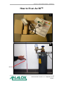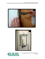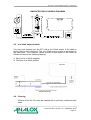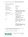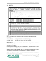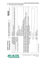
1
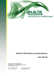
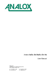
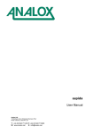
Ax 50™ Carbon Dioxide Analyser *** WARNING *** Please read the safety information on Pages 9 and 24 before installing this product. Analox Ltd. 15 Ellerbeck Court, Stokesley Business Park North Yorkshire, TS9 5PT, UK T: +44 (0)1642 711400 F: +44 (0)1642 713900 W: www.analox.net E: [email protected] This support line is closed on UK public holidays Analox 50 – Carbon Dioxide Analyser – User Manual How to fit an Ax 50TM 1 2 450mm Document Ref: A50-811-19 – September 2014 Page 2 Analox 50 – Carbon Dioxide Analyser – User Manual 3 4 Document Ref: A50-811-19 – September 2014 Page 3 Analox 50 – Carbon Dioxide Analyser – User Manual 5 6 Document Ref: A50-811-19 – September 2014 Page 4 Analox 50 – Carbon Dioxide Analyser – User Manual 7 8 Document Ref: A50-811-19 – September 2014 Page 5 Analox 50 – Carbon Dioxide Analyser – User Manual Ax 50TM Accessories h a g e c b i Document Ref: A50-811-19 – September 2014 Page 6 Analox 50 – Carbon Dioxide Analyser – User Manual Effects of Carbon Dioxide 1,000ppm (0.1%) 5,000ppm (0.5%) 10,000ppm (1%) 15,000ppm (1.5%) 20,000ppm (2%) 30,000ppm (3%) 40,00050,000ppm (4-5%) 50,000100,000ppm (5-10%) 100,0001,000,000ppm (10-100%) For a more detailed outline of the dangers of CO2, please visit our website www.analox.net or contact us at [email protected] Document Ref: A50-811-19 – September 2014 Page 7 Analox 50 – Carbon Dioxide Analyser – User Manual LIST OF CONTENTS 1. SAFETY NOTES ...................................................................................... 9 2. PACKAGING CONTENTS CHECK .......................................................... 9 3. ABOUT THE Ax 50TM .............................................................................. 10 3.1. 4. BATTERY BACK-UP ENDURANCE................................................ 11 INSTALLATION ...................................................................................... 12 4.1. Wall Mounting .................................................................................. 12 4.2. Remote Alarm Repeaters ................................................................ 13 4.2.1. To connect a “Hard Wired” Remote Alarm Repeater ................ 13 4.2.2. To connect a “Quick Connect” Remote Alarm Repeater .......... 14 4.2.3. To connect a “Strobe LED” Remote Alarm Repeater ............... 14 4.3. Alarm Relay Output Models ............................................................. 15 4.4. Relay Wiring .................................................................................... 16 4.5. 4 to 20mA output models ................................................................. 17 4.6. Cleaning .......................................................................................... 17 5. OPERATION........................................................................................... 18 5.1. 6. Operation at Altitude ........................................................................ 18 ALARM INDICATIONS ........................................................................... 18 6.1. 6.2. Lamp and Alarm Test ...................................................................... 19 Fault Conditions ............................................................................... 20 7. TECHNICAL SPECIFICATIONS ............................................................. 21 8. WARRANTY INFORMATION ................................................................. 22 9. DISPOSAL .............................................................................................. 23 10. SAFETY .................................................................................................. 24 11. DECLARATION OF CONFORMITY ....................................................... 25 Document Ref: A50-811-19 – September 2014 Page 8 Analox 50 – Carbon Dioxide Analyser – User Manual 1. SAFETY NOTES Every gas monitor installation should be risk assessed. The correct location of monitor(s) must consider the potential sources of gas leaks and the location of expected human occupation in the area. Where large areas must be monitored, it is often advised that no single monitor should cover a volume in excess of 80m3. The installation of more monitors should be considered where an area is complex in shape, filled with obstacles, has a lack ventilation or air circulation, or if there are dead zones where gas can collect a) The Ax 50TM must be installed according to these instructions which should be read entirely before commencing installation. b) For your convenience the Remote Alarm Repeater is pre-wired to the Ax 50TM sensor unit. c) If you need to disconnect the cable for ease of installation. DISCONNECT FROM THE REMOTE ALARM REPEATER END d) The system MUST NOT be switched on until all connections have been correctly made. e) We do not recommend you access the main unit. Potentially lethal voltages exist within the Ax 50TM. It should only be opened by a Qualified Technician, and must be isolated from the electrical supply before opening. f) The Ax 50TM does not require routine maintenance. All you need to do is check that the green light is flashing and press the mode button periodically to make sure that the Horn and alarm lights are functioning. 2. PACKAGING CONTENTS CHECK The following items are enclosed: a) Ax 50TM main unit, with power lead to a plug (where necessary) b) User manual for standard Ax 50TM c) Test certificate d) Rawl plugs and screws for wall mounting e) Remote Alarm Repeater and 8 metres of interconnecting cable connected to the Ax 50TM. f) Warning label Document Ref: A50-811-19 – September 2014 Page 9 Analox 50 – Carbon Dioxide Analyser – User Manual 3. ABOUT THE Ax 50TM The Ax 50TM unit is designed to detect the presence of Carbon Dioxide in ambient air for the protection of people in confined spaces. The Ax 50TM provides audible and visual indication of potentially dangerous levels of Carbon Dioxide in the air surrounding the instrument. The instrument uses an Infra Red detector system, together with state of the art technology. It is housed in an IP65 splash proof enclosure, and is designed to provide long, trouble free service, with minimum maintenance. The Remote Alarm Repeater mimics the status indicators on the main Ax 50TM. It also provides a push-button which operates in the same manner as the Mode switch on the Ax 50TM. If you have more than one entrance to your cellar or store room you may need more than one Remote Alarm Repeater. Up to three repeaters can be daisy chained (one repeater linked to another) covering up to three entrance doors. Optional items fitted to, or supplied with the unit may include the following (as shown in the photographs on Page 6): a) Extra Remote Alarm Repeaters b) Oxygen sensor* c) Medium duty relays* d) 4 to 20mA current loop output (or 0-1V)* e) Battery back-up* f) 4 digit display* g) Remote Alarm Repeater with high intensity strobe beacon* h) Splash guard i) Calibration gasses * Please note these items cannot be retro fitted. Document Ref: A50-811-19 – September 2014 Page 10 Analox 50 – Carbon Dioxide Analyser – User Manual 3.1. BATTERY BACK-UP ENDURANCE If fitted the Battery back-up will give the Ax 50TM between 7 and 14 hours normal operation in the event of a power failure, some examples are listed below: Instrument Type Battery Back-up Endurance Standard Ax 50TM with 1 Remote Alarm 14 Hours Ax 50TM including 4-20mA Output, 1 Relay Output and 2 Remote Alarms 11 Hours Ax 50TM including 4-20mA Output, 2 Relay Outputs and 2 Remote Alarms 7 Hours In normal operating conditions using an external power source (Mains AC or DC) the Battery Back-up should last up to approximately 5 years or 200 cycles. Document Ref: A50-811-19 – September 2014 Page 11 Analox 50 – Carbon Dioxide Analyser – User Manual 4. INSTALLATION 4.1. Wall Mounting The power socket that the equipment plugs into must be positioned so that it is close to the equipment and in easy reach of the operator. If the power supply for the Ax 50TM is not positioned so that it is close to the equipment and in easy reach of the operator, a local means of double pole isolation must be provided. Isolation can be achieved either by means of a non-locking plug or a double pole switch of suitable rating. A label must be placed by the local disconnection point for the Ax 50TM stating "REMOVE PLUG TO DISCONNECT Ax 50TM" The Ax 50TM should be mounted onto a wall using the mounting lugs on the unit. Rawl plugs and screws are provided for this purpose. It is not necessary to dismantle the Ax 50TM main unit in any way prior to installation. You need to ensure the mains plug fused at 5amp is in easy reach of a power socket. Attach the main unit to the wall 450mm from the floor as close to the valves and manifolds as possible. An 8 metre 8 core cable is pre-wired to the Ax 50TM and has a Remote Alarm Repeater pre-attached. Run the Remote Alarm Repeater cable to the outlet door, safely securing the cable with cable clips. A drilling template is included with this booklet. Document Ref: A50-811-19 – September 2014 Page 12 Analox 50 – Carbon Dioxide Analyser – User Manual 4.2. Remote Alarm Repeaters The Remote Alarm Repeater should be located at eye level and attached to the outside or immediately inside the access door. If you need to disconnect the Remote Alarm Repeater, reconnection is in one of the following ways:- 4.2.1. To connect a “Hard Wired” Remote Alarm Repeater 1) Disconnect the power supply from the Ax 50TM. 2) Open the Remote Alarm Repeater unit by removing the 4 screws in the front of the case and carefully pulling the case apart. The connecting wires from the Ax 50TM pass through one of the cable glands on the Remote Alarm Repeater. 3) Terminate the wires in accordance with the table below REPEATER CABLE COLOURS Type 1 Repeater Term 8 7 6 5 4 3 2 1 Type 2 (Cat 5) Ax 50 ST1 Terminal No 3 2 4 5 6 7 8 1 4) Replace the lid of the Remote Alarm Repeater, insert and tighten the 4 screws, and mount it in the desired position using the 2 fixing lugs. 5) Restore power to the Ax 50TM. Press the switch on the Remote Alarm Repeater once, and ensure that the four indicators flash. Note that in the presence of a genuine alarm, this test feature is disabled. Document Ref: A50-811-19 – September 2014 Page 13 Analox 50 – Carbon Dioxide Analyser – User Manual 4.2.2. To connect a “Quick Connect” Remote Alarm Repeater 1) Disconnect the power supply from the Ax 50TM. 2) Insert the connector on the end of the wire into either socket on the bottom of the Remote Alarm Repeater. 3) Restore power to the Ax 50TM. Press the switch on the Remote Alarm Repeater once, and ensure that the four indicators flash. Note that in the presence of a genuine alarm, this test feature is disabled. 4.2.3. To connect a “Strobe LED” Remote Alarm Repeater 1) Disconnect the power supply from the Ax 50TM. 2) Open the Remote Alarm Repeater unit by removing the 4 screws in the front of the case and carefully pulling the case apart. The connecting wires from the Ax 50TM pass through one of the cable glands on the Remote Alarm Repeater. 3) Terminate the wires in accordance with the table below REPEATER CABLE COLOURS Type 1 6 Ax 50 ST1 Terminal No 3 *See Note 4 4 5 5 4 6 3 7 2 8 1 1 Repeater Term 8 7 Type 2 (Cat 5) 4) For units NOT fitted with internal relay(s): Connect the free wire (Brown or Orange) to A50-231 main PCB at JP13 terminal 5. For units fitted with internal relay(s): Connect the free wire (Brown or Orange) to A50-231 main PCB at IC10 terminal 2 and move the wire from terminal 4 (Green/white or green) to terminal 2 of ST1. 5) Replace the lid of the Remote Alarm Repeater, insert and tighten the 4 screws, and mount it in the desired position using the 2 fixing lugs. Document Ref: A50-811-19 – September 2014 Page 14 Analox 50 – Carbon Dioxide Analyser – User Manual 6) Restore power to the Ax 50TM. Press the switch on the Remote Alarm Repeater once, and ensure that the four indicators and the LED strobe flash. Note that in the presence of a genuine alarm, this test feature is disabled. 4.3. Alarm Relay Output Models You may have ordered your Ax 50TM with relays (only 1 relay available if O2 sensor specified). Relays are available in 2 different formats as follows: Internal relays The relays are fitted internal to the main unit with a pre-wired 1m 6-core cable supplied connected to relay contacts. With all power isolated, make wiring connections to the Relay cable. The relay contacts are ‘Volt-Free’ single pole Changeover and are rated 50VAC/DC, 1 Amps (max). External relays A pre-wired junction box is supplied with the Ax 50TM main sensor unit. There is no need to open the main sensor unit. With all power isolated, make wiring connections to the Relay Terminal Box. The relay contacts are ‘Volt-Free’ single pole Changeover and are rated 240VAC/28VDC, 2 Amps (max). For either internal or external the relays are normally non-latching which means the relays will only activate when an alarm is raised and deactivate when the alarm cancels. Latched versions are available; if relays are latched they will only cancel once the alarm state has cleared, and the mode switch on the Ax 50TM or Remote Alarm Repeater is pressed. The relays are normally supplied ‘Fail Safe’ i.e. normally energised, and will de-energise when in alarm state. The relay will also be in its alarm state during the forty second warm up period. Document Ref: A50-811-19 – September 2014 Page 15 Analox 50 – Carbon Dioxide Analyser – User Manual 4.4. Relay Wiring Internal relays Ensure that the load is within the limits of the relay, 50VAC/DC, 1 Amps (max). Cable core Relay terminals Relay 1 COM Relay 1 N.O. Relay 1 N.C. Relay 2 COM Relay 2 N.O. Relay 2 N.C. External relays The cable gland is for cables of outside diameter between 5 and 7mm, if cable fitted is outside that range, a suitably specified cable gland must be used. Ensure that the gland is properly tightened. Test that the cable is adequately gripped by the cable gland. Ensure that the cable is suitable for purpose, the load is within the limits of the relay, 240VAC/28VDC, 2Amps, and the insulation of the external circuit meets the requirements for basic insulation 240VAC/28VDC, 2 Amps. After completing wiring, ensure that the terminal box cover is securely replaced. RELAY TERMINAL BOX TERMINATIONS Document Ref: A50-811-19 – September 2014 Page 16 Analox 50 – Carbon Dioxide Analyser – User Manual SIMPLIFIED RELAY WIRING DIAGRAM 4.5. 4 to 20mA output models You may have ordered your Ax 50™ with a 4 to 20mA output. A 2m cable is factory fitted to the instrument. The 4 to 20mA output current is generated by the instrument. The customer system should be connected to this cable as follows and as per the following drawing: 1) Blue wire 4 to 20mA negative 2) Red wire 4 to 20mA positive (Max load 150 Ω) 4.6. Cleaning All parts of the Ax 50TM may be cleaned with a soft cloth, moistened with water. Document Ref: A50-811-19 – September 2014 Page 17 Analox 50 – Carbon Dioxide Analyser – User Manual 5. OPERATION When mains power is first applied to the Ax 50TM, it requires a period of approximately 40 seconds to stabilise. During this period, The ‘Good/OK’ and ‘Fault’ status indicators will be turned on. The ‘Good/OK’ status indicator will flash briefly every few seconds, indicating normal operation and after the initial stabilising period has expired, the ‘Fault’ status indicator will turn off. The Ax 50TM will then be in its normal operating condition. During normal operation, the ‘Good/OK’ green light will flash on/off, thus indicating that the system is operating correctly. The green light status indicator on any Remote Alarm Repeaters will also flash on and off. 5.1. Operation at Altitude The toxic effects of Carbon Dioxide are dependent on the partial pressure, or the quantity of gas molecules, not the percentage in the atmosphere; therefore at altitudes above 900 metres (3000 feet) alarms will operate below the factory calibration point. Please refer to our website www.analox.net for details of suitable alarm set points and calibration procedures at altitude. 6. ALARM INDICATIONS Standard unit If the Ax 50TM detects a Carbon Dioxide concentration which exceeds the first alarm level, then the red First Alarm indicator will begin to flash and the Horn will sound. If the measured concentration of Carbon Dioxide continues to rise above the second alarm level, then the red Second Alarm indicator will also begin to flash and the pace of the Horn will increase. This condition will be repeated on any Remote Alarm Repeaters. The alarms are selfcancelling when the Carbon Dioxide level falls below the alarm limits. Alternatively latched alarm versions are available, on which the Ax 50TM will stay in the alarm mode until the gas concentration has fallen below the alarm set point and the mode switch has been pressed to accept the alarm. Alarm 1 Alarm 2 Document Ref: A50-811-19 – September 2014 Page 18 Analox 50 – Carbon Dioxide Analyser – User Manual Pre-alarm unit If the Ax 50TM has a 0.5% pre-alarm and it detects a Carbon Dioxide concentration which exceeds this first alarm level, then the red First Alarm indicator will begin to flash but the Horn will not sound. If the measured concentration of Carbon Dioxide continues to rise above the second alarm level, then the red Second Alarm indicator will also begin to flash and the Horn will sound. This condition will be repeated on any Remote Alarm Repeaters. The alarms are self-cancelling when the Carbon Dioxide level falls below the alarm limits. If the measured concentration of Carbon Dioxide continues to rise above the third alarm level, then the red third Alarm indicator will also begin to flash and the pace of the Horn will increase. This condition will be repeated on any Remote Alarm Repeaters. The alarms are selfcancelling when the Carbon Dioxide level falls below the alarm limits. Alarm 1 (Pre alarm) Alarm 2 Alarm 3 6.1. Lamp and Alarm Test Momentarily pressing the ‘Mode’ button on either the Ax 50TM or any Remote Alarm Repeaters, in the absence of any alarm conditions, causes a lamp and alarm test to be performed. The indicator lamps will flash 4 times, together with the alarm Horn. This test should be carried out each time the area is entered. Please note that the optional relays which may be fitted to the instrument are NOT operated during this test. Therefore any lights or sirens which may be connected to the instrument will NOT be tested by this operation. Document Ref: A50-811-19 – September 2014 Page 19 Analox 50 – Carbon Dioxide Analyser – User Manual 6.2. Fault Conditions During normal operation, the instrument carries out a continuous selftest procedure. As long as the green light is flashing, the instrument is working. If there are no indicator lamps lit on the Ax 50TM, check that power is connected and that the fuses are OK. 1) If the ‘OK’ indicator is permanently on, contact your Service Engineer. 2) If the fault light is illuminated and the Horn is sounding the unit needs attention and you should contact your Service Engineer. Fault Document Ref: A50-811-19 – September 2014 Page 20 Analox 50 – Carbon Dioxide Analyser – User Manual 7. TECHNICAL SPECIFICATIONS Carbon Dioxide Range 0.1-5% Response Time 60 Seconds to T90 Optional Oxygen Range 0.1 to 25% Operating Temperature -5 to +40°C Temperature Effect <0.1%FS/°C Sensor Type - Carbon Dioxide Analox Infra Red Detector, featuring microprocessor based compensation for temperature effects and IR source ageing Sensor Type – Oxygen Galvanic Electrochemical Cell Optional Display 4 digit Liquid Crystal Display Optional 4 to 20mA Output (or 0-1V) Gas Concentration Output (Max load 150 Ω) Alarms 2/3 x Carbon Dioxide Visual Indicators 1 x System Fault Indicator 1 x Status Indicator 1 x Optional Oxygen Visual Indicator Common Audible Alarm - Horn Relays Internal: 2 x Optional Independent Relays, VoltFree single pole Changeover, rated 50VAC/DC, 1 Amp, (only one relay if oxygen sensor specified). or External: 2 x Optional Independent Relays, VoltFree single pole Changeover, rated 240VAC/ 28VDC, 2 Amps, (only one relay if oxygen sensor specified). Analox has a policy of continuous improvement and we reserve the right to upgrade or change specifications without prior notice. The Analox 50TM conforms to DIN 6653-2:2004. Document Ref: A50-811-19 – September 2014 Page 21 Analox 50 – Carbon Dioxide Analyser – User Manual 8. WARRANTY INFORMATION We provide the following Warranties for the Ax 50™: A 15 year CO2 Sensor Warranty. A 2 year electronics Warranty. In both cases the Warranty period runs from the date of our Invoice. We warrant that the equipment will be free from defects in workmanship and materials. The Warranty does not extend to and we will not be liable for defects caused by the effects of normal wear and tear, erosion, corrosion, fire, explosion, misuse, use in any context or application for which the equipment is not designed or recommended, or unauthorised modification. The Warranty will be void and shall cease to be effective in the event that the main sensor unit is opened or in the event that any alterations or repairs are made or attempted except in accordance with any specific previous written authorisation from us. Following a valid Warranty claim in accordance with the above, the equipment, upon return to us, would be repaired or replaced without cost or charge but in our discretion we may elect instead to provide to you which ever is the lesser of the cost of replacement or a refund of net purchase price paid as per our Invoice on initial purchase from us. We shall have no liability for losses, damages, costs or delays whatsoever. We shall have no liability for any incidental or consequential losses or damages. All express or implied warranties as to satisfactory or merchantable quality, fitness for a particular or general purpose or otherwise are excluded and no such Warranties are made or provided, save as set out in this Clause 7. In order to effectively notify a Warranty claim, the claim with all relevant information and documentation should be sent in writing to: Analox Sensor Technology Limited 15 Ellerbeck Court Stokesley Business Park Stokesley North Yorkshire TS9 5PT Or by e-mail to : [email protected] Or by Fax to : +44 1642 713900 We reserve the right to require from you proof of dispatch to us of the notification of Warranty claim by any of the above alternative means. The equipment should not be sent to us without our prior written authority. All shipping and Insurance costs of returned equipment are to be born by you and at your risk. All returned items must be properly and sufficiently packed. Document Ref: A50-811-19 – September 2014 Page 22 Analox 50 – Carbon Dioxide Analyser – User Manual 9. DISPOSAL According to WEEE regulation this electronic product can not be placed in household waste bins. Please check local regulations for information on the disposal of electronic products in your area. Document Ref: A50-811-19 – September 2014 Page 23 Analox 50 – Carbon Dioxide Analyser – User Manual 10. SAFETY The Ax 50TM is designed to be compliant with the following standards: BS EN 610101: 2001, IEC 61010-1: 2001, CAN/CSA C22.2 Nr. 61010-1-04, ANSI / UL Std. No. 61010-1 (2nd edition). It is designed to be safe at least under the following conditions. a. Indoor use b. Altitude up to 2000m c. Temperature -5°C to +40°C d. Maximum relative humidity 80% for temperatures up to 31°C decreasing linearly to 50% relative humidity at 40°C. e. Mains voltage supply fluctuations not to exceed 10% of the nominal voltage f. Impulse withstand (over-voltage) category II of IEC 60364-4-443 g. Pollution degree 2 h. Mains voltage:230V AC (Not Adjustable - Instrument will be factory set) 110V AC (Not Adjustable - Instrument will be factory set) 24V DC (Not Adjustable - Instrument will be factory set) i. Mains power:Less than 5VA – 110V AC and 230V AC Versions Less than 5W – 24V DC Version. j. Mains frequency - 50/60Hz k. The Quick Connect Remote Alarm Repeater has ingress protection to IP43: direct sprays of water up to 60 from the vertical in accordance with EN 60529:1991 + A1. The Main Unit, Hard Wired Remote Alarm Repeater, Battery Backup and Relay Terminal Junction Box all have ingress protection to IP65: low pressure water jets from all directions and totally protected from dust in accordance with EN 60529:1991 + A1. l. Insulation: - Reinforced insulation, class II product according to IEC536. m. Not for use in corrosive or explosive atmospheres n. Not approved for use in vehicles, ships or aircraft NOTE: Item ‘n’ of the above table only relates to CSA requirements (North America only) Fuse ratings:230V AC, 500mA, 110V AC, 500mA, 9-24V DC, 200mA, F rating 250V (20mm x 5mm Glass Cartridge) F rating 250V (20mm x 5mm Glass Cartridge) AS rating 250V (20mm x 5mm Glass Cartridge) Battery Back-Up:The Battery Back-Up is non repairable. refurbishment/replacement. Please return faulty units to Analox for 4 to 20mA (or 0-1V) Output:External connected equipment must meet the requirements for reinforced insulation or must be a Safety Extra Low Voltage (SELV) circuit as defined in IEC60950-1. The above statement refers to the risk of externally connected equipment introducing hazardous voltages into the A50 (O2NE, Safe-Ox or CO Clear). It is the responsibility of users of this product to ensure that their equipment/accessory is safe before connecting it. NOTE - If the equipment is used in a manner not specified by the manufacturer, the protection provided by the equipment may be impaired. Document Ref: A50-811-19 – September 2014 Page 24 Analox 50 – Carbon Dioxide Analyser – User Manual 11. DECLARATION OF CONFORMITY Document Ref: A50-811-19 – September 2014 Page 25