1
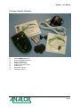
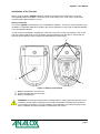
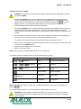
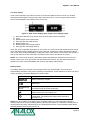
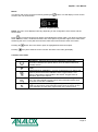
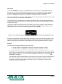
aspida User Manual Analox Ltd. 15 Ellerbeck Court, Stokesley Business Park North Yorkshire, TS9 5PT, UK T: +44 (0)1642 711400 F: +44 (0)1642 713900 W: www.analox.net E: [email protected] aspida – User Manual Contents Contents .................................................................................................................................................. 1 Safety Information ................................................................................................................................... 3 Package Contents Checklist.................................................................................................................... 4 About the Product .................................................................................................................................... 5 Sensor Options Available ................................................................................................................ 5 aspida Main Features ..................................................................................................................... 6 Installation of the Product ........................................................................................................................ 7 Battery installation ........................................................................................................................... 7 Charging the Analox aspida ........................................................................................................... 8 Operation ................................................................................................................................................. 9 Button functions ............................................................................................................................... 9 Switching the device on/off .............................................................................................................. 9 User registration............................................................................................................................... 9 The main display ............................................................................................................................ 10 Battery status ................................................................................................................................. 10 Menus ............................................................................................................................................ 11 Common menu items ..................................................................................................................... 11 Gas alarms..................................................................................................................................... 12 Global alarm options ...................................................................................................................... 13 Alarm latching ................................................................................................................................ 13 Alarm muting .................................................................................................................................. 13 Data Logging.................................................................................................................................. 14 Man-down alarm ............................................................................................................................ 14 Panic Alarm.................................................................................................................................... 14 Time-weighted average (TWA) monitoring of carbon dioxide ....................................................... 15 Maintenance Reminders ................................................................................................................ 16 Calibration reminders ..................................................................................................................... 16 Sensor replacement reminders ...................................................................................................... 16 Faults ............................................................................................................................................. 17 Troubleshooting ............................................................................................................................. 17 Maintenance .......................................................................................................................................... 18 Calibration ...................................................................................................................................... 18 Oxygen fresh air calibration ........................................................................................................... 18 Oxygen sensor replacement .......................................................................................................... 20 Cleaning ......................................................................................................................................... 26 Specifications ........................................................................................................................................ 27 Warranty information ............................................................................................................................. 28 Disposal ................................................................................................................................................. 29 WEEE statement ........................................................................................................................... 29 Oxygen sensor disposal ................................................................................................................ 29 Declaration of Conformity ...................................................................................................................... 30 Document Ref: PGA-801-10 - December 2014 Page 1 aspida – User Manual Safety Information WARNING: Read the safety information fully before using the aspida. High volume audible alarm The aspida employs high volume warning alarms with a sound pressure level of 95dB in the case of normal gas alarms, and up to 110dB in the case of the man-down alarm. Care should be taken particularly when the man-down feature is enabled to minimise exposure to the sounder. The aspida unit should always be worn away from the head in order to minimise close range exposure to the alarm. WARNING: The 110dB man-down alarm can be manually activated at any time by holding the button. Care should be taken not to activate this alarm when the aspida unit is in close proximity to the ears. Electrochemical oxygen sensor The oxygen sensor used in certain aspida options is an electrochemical sensor which contains toxic compounds. Under normal conditions the sensor will be safely sealed. To prevent leakage, the unit must not be exposed to temperatures outside the specified range, or be exposed to organic vapours, which may cause physical damage to the body of the sensor. The unit must not be stored in areas containing organic solvents or in flammable liquid stores. WARNING: Read the safety information fully before using the aspida. Sensor faults If the unit indicates a fault the user is no longer protected and should evacuate from areas used to store CO2 Document Ref: PGA-801-10 - December 2014 Page 3 aspida – User Manual Package Contents Checklist a) b) c) d) e) f) g) h) Analox aspida main unit 2xAA rechargeable batteries Belt clip attachment Charger power supply USB communication cable Software disc Quick start manual Calibration adapter Document Ref: PGA-801-10 - December 2014 Page 4 aspida – User Manual About the Product The Analox aspida is a portable, personal, gas detection instrument capable of detecting potentially dangerous ambient levels of oxygen and carbon dioxide for protection of people working in confined spaces. The instrument gives clear audible, visible and vibration warning of potentially dangerous gas levels. A high resolution Organic Light-Emitting Diode (OLED) display shows clear, live gas level readings in all light conditions. The Analox aspida is housed in a robust, IP65 splash proof enclosure and is designed to attach securely and comfortably to clothing. The instrument operates using rechargeable battery technology, allowing it to run for more than 12 hours continuously between charges. The Analox aspida allows for easy replacement of the rechargeable batteries with standard, AA, non-rechargeable batteries in circumstances where recharging is not possible. As an additional safety feature, the Analox aspida provides an optional man-down/panic alarm feature, designed to give a lone-worker peace of mind when working in enclosed areas. When enabled with this feature, the aspida monitors the user’s movements and sounds an ultra-loud siren if they should become incapacitated. In addition, a user-activated panic feature can initiate the ultraloud siren to signal for help. Additional feature of the Analox aspida include time-weighted average monitoring of carbon dioxide levels, multiple user registration for shared devices and a continuous 7 day internal data log. All features are fully configurable through USB using the Analox aspida Intelligent Configuration Software. Sensor Options Available The Analox aspida is available in three sensor configurations: a) b) c) Carbon dioxide – single sensor Oxygen – single sensor Carbon dioxide and oxygen - dual sensor Document Ref: PGA-801-10 - December 2014 Page 5 aspida – User Manual aspida Main Features 1 6 9 2 10 3 11 4 7 5 8 12 13 Figure 1 - Main features 1) 2) 3) 4) 5) 6) 7) 8) 9) 10) 11) 12) 13) Alarm, fault and OK LEDs Carbon dioxide gas port (if sensor fitted) Cancel/exit/panic-alarm button Cycle button Confirm/on/off button Oxygen gas port (if sensor fitted) OLED display Horn Belt loop mount Charger socket USB communication socket Battery compartments Lanyard pin Document Ref: PGA-801-10 - December 2014 Page 6 aspida – User Manual Installation of the Product Before using the Analox aspida, batteries should be inserted into the instrument. If using the rechargeable batteries provided, it should be given a full charge cycle. A full charge cycle will be complete within approximately 4.5 hours. Battery installation The Analox aspida is powered by a pair of standard AA batteries. The device can be powered using the NiMH re-chargeable batteries included in the product package or using a pair of standard Alkaline, non-rechargeable batteries. To gain access to the battery compartment, undo the screw in the centre of the battery cover on the rear of the device and lift the cover off. Before removing batteries from the device, ensure that it is switched off and that the mains charger and USB cable are disconnected. 2 1 3 Figure 2 - Battery compartment 1) Battery compartment access screw 2) Sensor compartment access screws 3) Battery compartments WARNING: Care should be taken when inserting batteries, paying particular attention to the orientation of each battery. Markings on the inside of the battery compartment indicate the correct battery orientation. Incorrect orientation of the batteries may result in damage to the device. Batteries should be inserted by hand without use of tools. Document Ref: PGA-801-10 - December 2014 Page 7 aspida – User Manual Charging the Analox aspida WARNING: The following safety warnings should be observed before attempting to charge the Analox aspida: The Analox aspida should only be charged when the NiMH batteries supplied with the product are fitted. Attempting to recharge non-rechargeable alkaline batteries will in most cases result in an aborted charge, and this will be indicated by a flashing icon on the display. However, connecting the mains charger whilst using alkaline batteries is not recommended and may result in damage to the device. The Analox aspida may be used with standard rechargeable AA batteries which have been charged using a third-party charging device. However, only NiMH batteries provided by Analox should be used when attempting to charge batteries within the device using the mains charger. Do not attempt to charge the device using a mains charger other than the one supplied with the device. Use of an incorrect mains charger may damage the device. The battery cover should always be securely fitted before performing a charge. With the mains charger disconnected from the wall outlet, insert the power jack into the socket on the rear of the aspida device. Insert the mains charger into the wall outlet. Switch on the mains outlet. NOTE: The unit can be charged whilst switched on or switched off. The following lists the conditions that may be observed during a charge. Battery icon state Audible warning Charge status >> (animated) None Charging (charge setup) >> >> None Charging >> (animated) None Charging (approx. 1.5 hours remain) Success beep Charge complete Fault beep Charge fault Fault beep No batteries (flashing) (animated) NOTE: If an attempt is made to charge non-rechargeable batteries, a fault will be indicated by a flashing icon. The normal charge period for a set of flat batteries is approximately 4.5 hours. WARNING: During charging, the device will warm up. This effect is normal. It is however suggested that the device is charged indoors at room temperature to ensure a full charge cycle completes. Document Ref: PGA-801-10 - December 2014 Page 8 aspida – User Manual Operation Button functions The Analox aspida has three buttons that are used as follows: Button Function Power on/off Confirm Select button Show device menu Cycle through options Cancel Return to main screen Switching the device on/off To switch the Analox aspida on, press the button. After a few seconds, the main gas display screen will be shown. If multiple user-names are registered to the device then the user-name selection screen will be shown instead. See the section ‘User registration’ for further instructions. On start-up, the sensors have a short warm-up period. Live gas values will not be displayed until the sensors have completed their warm-up. For oxygen, the warm-up takes 15 seconds. For carbon dioxide, the warm-up takes 30 seconds. Sensor warm-up will be shown on the display. To switch off the device, press and hold the button. button until the screen goes blank then release the User registration The Analox aspida allows for registration of up to two usernames. This allows multiple users to share use of the device. On start-up, a username is selected, and all subsequent gas information is logged internally against the selected user ID. Users can be registered to a device using the aspida configuration software. See the aspida configuration software for instructions. On device power up, if a single user is registered, the username will be displayed for a few seconds, after which the device will operate normally. If 2 users are registered, both usernames will be displayed in a menu for the user to select. Pressing the user. button will cycle between highlighted usernames. The button will select the highlighted NOTE: If a user is not selected within 2 minutes of start-up, a ‘no user’ ID will be selected automatically and the device will continue to run normally. During this time, a reminder beep will be sounded to prompt the user to select an ID. Document Ref: PGA-801-10 - December 2014 Page 9 aspida – User Manual The main display Under normal operation, gas values for each of the sensors fitted are shown in their own window along with the description of the gas type and measurement units. The current gas value for each sensor will be updated on the display once per second. Figure 3 - Dual sensor display (left), single sensor display (right) 1) 2) 3) 4) 5) 6) 7) Man-down detection (only shown when the man-down feature is enabled) Clock Measured gas value (dual sensor) Gas type and units (dual sensor) Battery status icon Measured gas value (single sensor) Gas type and units (single sensor) If the user does not operate any buttons for one minute, the screen-saver will activate showing a logo which will drift around the display with the screen dimmed. Pressing any button will wake the device from screen saver mode and display the main gas screen. If the device is connected to the charger or to a PC via USB, the screen-saver will not activate but the screen will still dim as normal. NOTE: The screen-saver function is intended to extend the battery life and prevent screen burn-in. During screen saver mode, gas values are still monitored as normal. Any gas alarm will wake the display from screen saver immediately and the main gas display will be shown. Battery status The battery status icon is shown in the top right hand corner of the display. This icon gives a representative indication of the power remaining in the batteries. As the batteries run down from full to empty, the battery icon will be displayed in various states. Icon Battery status Battery sufficiently charged , Battery low (flashing) Battery near empty. Approx. 1 hour of operation remaining. A reminder beep will sound periodically. The device is powered from the mains charger. The icon will be shown next to the battery icon. The device is attached to and powered by a computer via a USB cable. The USB symbol will be shown instead of the battery icon. NOTE: Due to the nature of the battery type, the battery status icon may temporarily indicate a capacity higher than the true remaining battery capacity upon switch-on. This effect is usually seen in devices which have been switched off for an extended period of time. The true battery status will be indicated within a few minutes of power-up. Document Ref: PGA-801-10 - December 2014 Page 10 aspida – User Manual Menus The device main menu can be accessed by pressing the similar to the one shown below. button. This will display a menu screen Figure 4 - A typical menu NOTE: The menu icons displayed will vary depending on the configuration of the device and the sensor fitted. Press to cycle through the menu options and highlight the chosen option. If an arrow is present at either end of the menu, it indicates that there are more options beyond the edges of the visible menu. Advancing the menu cursor past the end of the visible menu will reveal the extra menu items. Pressing the Pressing button when the chosen option is highlighted will select that option. at any time whilst the menu is shown will return to the main gas display. Common menu items Menu Icon Function Information - Selecting this menu item will display a screen with information related to the specific device, such as serial number and firmware version. Back - Selecting back exits the menu and returns to the main gas display. Oxygen fresh-air calibration - (oxygen configurations only) Select this option to perform a fresh-air calibration of the oxygen sensor. This feature is described in further detail in the section ‘Oxygen fresh air calibration’ later in this manual. Carbon dioxide sensor information - (Carbon dioxide configurations only). This option displays a page which gives information about when the sensor is next due a calibration. Oxygen sensor information - (Oxygen configurations only). This option displays a page which gives information about when the sensor is next due a calibration and also when replacement of the sensor is due. Document Ref: PGA-801-10 - December 2014 Page 11 aspida – User Manual Gas alarms The Analox aspida has a range of configurable alarms to warn the user of potentially dangerous atmospheres. For each gas sensor fitted to the device, up to 3 configurable alarms are available. In the case of carbon dioxide, an extra Time Weighted Average (TWA) alarm is provided. See the section ‘Time-weighted average (TWA) monitoring of carbon dioxide’ for more details. In the case of an alarm condition being detected, the horn will activate giving an audible warning to the user. At the same time, the red alarm LEDs will flash. The device also has a vibrating alert to accompany gas alarms. When an alarm is triggered the unit will vibrate for 10 seconds after which the vibration will stop. The unit will not vibrate whilst connected to USB or the charger. A gas alarm condition will also be shown on the display, giving a clear indication of the gas that has triggered the alarm. In the case of an alarm, the gas warning symbol will appear below the gas reading which will be surrounded by a flashing border, as shown below. Figure 5 - The main gas display showing that carbon dioxide levels have triggered an alarm Each alarm is configurable as either high-going or low-going. In the case of a high going alarm, if the gas value exceeds the configurable set-point, the alarm will be activated. The 3 gas alarms are also ranked in order of priority, so that if a more dangerous level of gas is detected, the user is notified. Example Two alarms are configured for detection of oxygen levels. Priority 1 alarm is configured as a low going alarm with a set-point of 18.0%. Priority 2 alarm is configured as a low going alarm with a set-point of 19.5%. If using this setup the detected level of oxygen falls below 19.5%, priority 2 alarm will be activated. The red LEDs, vibration and horn will all activate, pulsing at a moderate rate, and a visual warning will be given on screen. The oxygen value will be highlighted and the gas warning symbol shown below the reading. If the detected oxygen level falls further so that it is below 18.0%, priority 1 alarm will be activated. This alarm is of a higher priority than the priority 2 alarm so the urgency of the alarm will be increased. The LEDs, vibration and horn will begin to pulse more rapidly to indicate that the severity of the alarm has increased. Document Ref: PGA-801-10 - December 2014 Page 12 aspida – User Manual Global alarm options There are two configurable options which affect all of the Analox aspida's alarms. Muting and latching options are set using the aspida configuration software. See the aspida configuration software manual for instructions. Alarm latching Sometimes it is useful for a user to be alerted of a harmful gas level, even after level of gas has dropped to a safe level. The Analox aspida can be configured to use latching alarms so that alarms triggered by harmful gas levels will not be missed. The latching alarms option can be enabled using the aspida configuration software. If the device is configured to use latching alarms then any alarm that is triggered will remain active until it is acknowledged by pressing the button. Example If a high-going alarm is activated by an increasing level of gas, the alarm will continue to sound even after the gas level has dropped below the alarm set-point. The alarm can be acknowledged by pressing the button when the gas reading has fallen below the set-point. In the case of multiple alarms, the highest priority alarm that was triggered will be latched. If the priority 1 alarm is latched and the gas level drops below the priority 1 set-point, pressing the button will clear the priority 1 alarm, however, if the gas level is still sufficient to trigger the priority 2 alarm, the device will continue to alarm at a priority 2 level. Alarm muting Sometimes it is desirable to be able to mute the horn or stop the device vibrating when an alarm is triggered. The Analox aspida provides an option to allow alarms to be muted. The mutable alarms option can be set using the aspida configuration software. If the alarm muting option is set on the device, any active alarm can be silenced by pressing the button whilst in an alarm state. Pressing will deactivate the horn and the vibration. The red LEDs and the on-screen warning will continue to flash until the alarm condition is cleared by safe levels of gas. In the case where a lower priority alarm has been muted and a higher priority alarm is triggered, the alarms will be un-muted. Example If a priority 2 alarm is activated and muted and the detected gas level changes so as to activate a priority 1 alarm, the horn and vibration will re-activate to warn the user of the increased severity. A muted alarm will not be un-muted in the case where the alarm level drops to a lower priority. Document Ref: PGA-801-10 - December 2014 Page 13 aspida – User Manual Data Logging The Analox aspida has a built in data-logging facility which will automatically log gas readings for all fitted sensors whenever the device is active. Readings are logged every 30 seconds to internal memory. The device is capable of storing over 7 days of continuous data. All data is logged with a date and time stamp, and if multiple users are registered with the device, each set of readings is logged against the selected user ID. The data-log can be downloaded from the device for analysis using the aspida configuration software. See the aspida configuration software manual for instructions. Man-down alarm The Analox aspida is equipped with a man-down alarm. If the man-down alarm feature is enabled the aspida device will monitor any movement the device is subject to. If the user who is wearing the alarm is somehow incapacitated, an alarm will be sounded to alert others in the nearby area of the accident. NOTE: By default, the feature is disabled. Enabling or disabling the alarm is performed using the aspida configuration software (see the section on alarm settings for further details). If the man-down feature is enabled, the device will sound a low volume pre-warning alarm after it detects no movement over a period of 4 minutes. The pre-warning alarm will sound for a period of 1 minute, during which a simple shaking of the device or pressing the button will reset the alarm timer. If after this 1 minute period there has still been no movement detected then the device will activate its ultra loud siren to warn others of the incident. Once the high volume alarm has been activated, the alarm can only be cancelled by pressing the condition, following screen will be shown. button. During a man down alarm Figure 6 - Display shown when the man-down alarm is triggered WARNING: Care must be taken whilst using the aspida device with the man down alarm activated. If the device is detached from the user's person and left on a stationary surface, the man-down condition will be triggered. This can lead to unintentional activation of the very high volume siren. As this siren sounds in excess of 100dB, this may be potentially harmful to hearing. To avoid nuisance alarms, the device should be switched off when left unattended. NOTE: The man-down high volume siren causes a large strain on the aspida’s batteries and as such, the expected operating period for the device is significantly reduced if the man-down alert is allowed to run for extended periods of time. Panic Alarm In cases where a worker is in distress and still conscious, it is possible to activate the ultra-loud siren manually. To activate the panic alarm, press and hold the button. Document Ref: PGA-801-10 - December 2014 Page 14 aspida – User Manual Time-weighted average (TWA) monitoring of carbon dioxide Carbon dioxide is toxic to the human body as concentrations increase. Short term exposure to the gas can be potentially lethal. Longer term exposure to more moderate levels of carbon dioxide can also be detrimental to health, so health and safety bodies (i.e. UK HSE) define occupational exposure levels (OEL) for the gas. These OELs provide a recommended safe exposure to carbon dioxide whilst under working conditions. The occupational exposure levels are based on a calculated time-weighted average (TWA) level of carbon dioxide in any one 24 hour period. The TWA calculation is based on average carbon dioxide levels weighted to an assumed standard 8-hour daily working shift. The Analox aspida has a facility which automatically calculates a TWA value on a per-user basis. When a user powers on the device and selects a user ID, the Analox aspida begins calculating and continuously updating that user’s own TWA. The device also takes into account any historic data from the last 24 hours which is relevant to the selected user. TWA data is logged alongside the actual gas readings in the internal data log. NOTE: If no users IDs are registered to the device, the TWA values will all be attributed to a default user. An alarm feature is provided which will warn of a high TWA exposure to carbon dioxide. In addition to the normal 3 available gas alarms per sensor, carbon dioxide sensors have a 4th alarm (priority 4) which is triggered when the calculated TWA value exceeds the TWA set-point. This alarm is set by default to the UK HSE recommended OEL for carbon dioxide of 5000ppm (0.5%). When this alarm is triggered, the red LEDs, vibration and horn warnings will activate as with other gas alarms. In the case of a TWA alarm, ‘TWA’ will be shown below the carbon dioxide reading on the display, as shown below. The TWA alarm is the lowest priority alarm and as such will be over-ridden by any gas alarms triggered by a short term increase in carbon dioxide levels. Figure 7 - The main gas display showing that to user has exceeded their TWA exposure to carbon dioxide As with the standard gas alarms, the TWA alarm can also be fully configured using the aspida configuration software. Document Ref: PGA-801-10 - December 2014 Page 15 aspida – User Manual Maintenance Reminders The aspida has the ability to track the due dates for the various maintenance tasks that are required during the products life and will display a warning symbol on the display when a maintenance task is due. Reminders will be shown for the following tasks. Sensor calibration due (carbon dioxide and oxygen sensors) Sensor replacement due (oxygen sensors only) The due dates for maintenance tasks can be viewed at any time by accessing the sensor information screen for each sensor by selecting either Figure 8. or from the main menu. An example is shown in Figure 8 - Oxygen sensor information Calibration reminders When a sensor is due for a re-calibration, the calibration due reminder symbol ( ) will be displayed flashing below the reading of the sensor that is due calibration, as shown in Figure 9. This symbol will continue to flash until a calibration has been performed. Figure 9 - Carbon dioxide calibration due reminder In the case of an oxygen sensor, the calibration due reminder will be cleared upon a successful fresh air calibration. In the case of a carbon dioxide sensor, the reminder will only be cleared once a span and zero calibration have been performed consecutively. See the ‘Calibration’ section of this manual for details of how to calibrate the sensors. Sensor replacement reminders Oxygen sensors will need to be periodically replaced as they deplete. When an oxygen sensor is due to be replaced, the replacement due reminder icon ( ) will be displayed flashing below the sensor’s gas reading, as shown in Figure 10. See the ‘Oxygen sensor replacement’ section of this manual for details of how to replace the oxygen sensor. The sensor replacement reminder can only be reset by using the aspida configuration software. See the aspida configuration software manual for details of how to reset the sensor replacement reminder. Figure 10 - Oxygen replacement due reminder Document Ref: PGA-801-10 - December 2014 Page 16 aspida – User Manual Faults If at any point during operation, the device develops a fault, an audible alarm will be sounded and the amber LED will flash. A fault will also be indicated by a symbol on the display top bar. If the fault is related to a particular sensor, the sensor window will show ‘---‘ and the symbol will be shown below the sensor’s gas reading window, as shown below. A fault alarm can be acknowledged by pressing the button. Figure 11 - Display showing a carbon dioxide sensor fault WARNING: If at any time the GREEN ‘OK’ LED is not flashing and the AMBER ‘FAULT’ LED is flashing the aspida must not be used and the supplier should be contacted, the user is no longer protected and should evacuate from areas used to store CO2. Troubleshooting Symptom Device does not switch on Device does not switch on Possible cause No batteries, or incorrectly orientated batteries Batteries are flat Batteries will not charge ( shown flashing) Batteries may not be rechargeable type Batteries will not charge ( shown flashing) Aged batteries causing a charge fault Batteries will not charge ( shown) Battery charge completes but battery life is short No batteries fitted Flashing symbol underneath gas reading Flashing symbol underneath oxygen gas reading The sensor is due a recalibration The oxygen sensor is due to be replaced Battery aging reduced battery capacity Action Check that batteries are inserted correctly Check that the batteries are inserted correct and are rechargeable NiMH then perform a device charge. Check that the batteries fitted are the rechargeable NiMH batteries supplied with the aspida Contact supplier for information about replacing rechargeable batteries Check that rechargeable batteries are fitted Contact supplier for information about replacing rechargeable batteries Refer to the section ‘Calibration’ of this manual for instructions Refer to the section ‘Oxygen sensor replacement’ of this manual for instructions Document Ref: PGA-801-10 - December 2014 Page 17 aspida – User Manual Maintenance Calibration It is normal that the aspida’s sensor readings will drift over time. It is therefore important that the sensors are periodically re-calibrated. The regularity of calibration depends upon the sensor. Carbon dioxide sensors should be calibrated every 12 months. Oxygen sensors should be calibrated every 2 months. Oxygen calibration should be performed in fresh air as described in the next section. Carbon dioxide calibration should be performed using the aspida calibration kit and aspida configuration software. See the aspida configuration software user manual for instructions for calibrating a carbon dioxide sensor. Oxygen fresh air calibration Due to the nature of the electrochemical technology of the oxygen sensor in the Analox aspida, the sensor output will drift over time. To allow the calibration of the oxygen monitor to be adjusted without the need to apply a full zero and span calibration, the aspida has a function which allows the user to span calibrate oxygen monitoring in fresh air. This feature is only available on devices where an oxygen sensor is fitted. WARNING: The fresh air calibration of oxygen is only intended to be performed in ambient air. The calibration assumes an atmospheric oxygen concentration of 20.9%. The fresh air calibration should not be performed indoors. To perform an oxygen fresh air calibration: 1) Take the Analox aspida outdoors into fresh ambient air. (If moving the device outdoors exposes it to a sharp temperature change it is recommended that the device be allowed 5 minutes to allow the temperature of the device to stabilize.) 2) Hold the device at arm’s length throughout the calibration procedure to ensure that breathing on the sensor inlets does not affect the calibration. 3) Press the button to access the device menu. 4) Highlight the icon and press . 5) The following confirmation screen will be presented. Press to begin the calibration or press to cancel. Figure 12 - Oxygen fresh air calibration confirmation screen 6) The unit will now sample the ambient air for 30 seconds to detect a stable oxygen reading. The progress of the sampling will be displayed on screen as shown below. Figure 13 - Calibration progress Document Ref: PGA-801-10 - December 2014 Page 18 aspida – User Manual 7) When the sampling process has complete, an audible alert will be given and the calibration confirmation screen will be shown as below. Figure 14 - Oxygen fresh air calibration failed Figure 15 - Oxygen fresh air calibration passed 8) If the calibration passed then the tick icon will be shown. The new calibration information will then be stored to the device memory and the device is ready for use. Press the button to confirm the operation and return to the main screen. 9) If a stable oxygen reading cannot be detected then the confirmation screen will show a cross icon. Press the button to acknowledge the failed calibration. A failed calibration will leave the previous oxygen calibration unchanged. To attempt the calibration again repeat steps 3 – 8. 10) Once calibrated successfully, the calibration due date for the oxygen sensor will be reset. The next calibration due reminder will occur in 2 months. NOTE: If an oxygen fresh air calibration is started accidentally, the operation can be cancelled at any time during its sampling stage by pressing the button. This will sound an audible fail beep and the calibration failed screen will be displayed. Press the to the main screen. button to acknowledge the failure and return Document Ref: PGA-801-10 - December 2014 Page 19 aspida – User Manual Oxygen sensor replacement Due to the electrochemical nature of the oxygen sensor used in certain aspida configurations, the sensor output will deplete over time, the expected life of the sensor is 2 years ( With a 1 year warranty), depending on usage. After a 2 year period of service, or when the sensor has depleted, the oxygen sensor should be replaced with a fresh sensor. (Contact supplier for a replacement sensor). WARNING: Before replacing the sensor, disconnect from any USB cable or charger, switch the device off, open the battery compartment and remove the batteries from the device. To replace the oxygen sensor: 1) Remove the top 4 screws (see Figure 2) from the device using a cross-head screwdriver as shown in Figure 16. Figure 16- Remove the sensor cap screws 2) Gently remove the sensor cap as shown in Figure 17. Figure 17 - Remove the sensor cap Document Ref: PGA-801-10 - December 2014 Page 20 aspida – User Manual 3) Locate the alignment rib on the sensor extraction tool as shown in Figure 18. Figure 18 - Locate the alignment rib 4) Gently slide the sensor extraction tool over the oxygen sensor (right hand sensor) being careful not to cause damage to the carbon dioxide sensor (left hand sensor, if fitted). Ensure that the alignment rib on the extraction tool lines up with the alignment marker on the aspida case as shown in Figure 19. Figure 19 - Align the extraction tool Document Ref: PGA-801-10 - December 2014 Page 21 aspida – User Manual 5) The extraction tool should now be positioned as shown in Figure 20. Figure 20 - Correct extraction tool position 6) Squeeze the grip on the extraction tool so as to achieve a firm hold on the oxygen sensor as shown in Figure 21. Figure 21 - Squeeze the extraction tool Document Ref: PGA-801-10 - December 2014 Page 22 aspida – User Manual 7) Lift the extraction tool vertically away from the device and the oxygen sensor should lift out of its socket as shown in Figure 22. Figure 22 - Removing the oxygen sensor 8) Remove the old sensor from the extraction tool by gently pushing the sensor from the wide, top end of the extraction tool. 9) Remove the new sensor from its packaging including the protective paper ring on the foam seal. Figure 23 - Insert the new sensor into the extraction tool 10) Insert the new sensor as show in Figure 23, ensuring that the blue plastic pin of the new sensor is aligned with the extraction tool alignment rib, as shown in Figure 24. Document Ref: PGA-801-10 - December 2014 Page 23 aspida – User Manual Figure 24 - Align the new sensor in the extraction tool Align the extraction tool rib with the aspida case alignment mark as in step 4 as shown in Figure 25. Figure 25 - Align the new sensor with the aspida device Document Ref: PGA-801-10 - December 2014 Page 24 aspida – User Manual 11) Push the tool and sensor gently downwards into the case until the sensor locates firmly within its socket. 12) Hold the top ring of the extraction tool gently, without squeezing the grip (Figure 26) and lift the tool vertically upwards to remove the extraction tool whilst leaving the new sensor in place. (A gentle twisting of the tool may help to separate the tool from the sensor). Figure 26 - Remove the extraction tool 13) Replace the sensor cap and fit the 4 cross-head screws (including washers) into the rear of the case as shown in Figure 27. Figure 27 - Replace the sensor cap and secure the screws WARNING: Any new sensor fitted to a device will take time to settle to a stable reading. For this reason, once the sensor has been fitted, the device should be left un-powered for at least 2 hours before attempting to power-up and calibrate. Once the sensor has been allowed to settle, replace the batteries and fit the battery cover. Power the device and allow the sensor(s) to warm up. The new oxygen sensor will require calibration and may be showing a fault due to an over-range reading (this is normal for a new sensor). To calibrate the oxygen sensor, follow the instructions in the section ‘Oxygen fresh air calibration’. Document Ref: PGA-801-10 - December 2014 Page 25 aspida – User Manual NOTE: The oxygen sensor may require further fresh air calibrations as the sensor continues to settle. The oxygen reading should be checked frequently in fresh air during the first few hours of operation with a new oxygen sensor. If the sensor change was prompted by a sensor replacement reminder ( icon), the reminder should be reset using the aspida configuration software. See the aspida software configuration manual for instructions. Cleaning The aspida should be cleaned using a damp cloth only. Abrasive or solvent products should not be used. Document Ref: PGA-801-10 - December 2014 Page 26 aspida – User Manual Specifications Operating temperature: -5 to 50°C Display: High-visibility, Organic Light Emitting Diode (OLED) Display Alarm horn: 95dB @ 30cm (110dB – man-down alarm) LED indicators; 1 x Green – OK 1 x Amber – Fault 3 x Red – Alarm Internal data log: 1 log every 30 seconds for at least 7 days of continuous use Batteries: 2 x NiMH 2100 mAh AA batteries Battery discharge time: 15 hours under normal operation (passive atmospheric monitoring, minimal user interaction, no alarms) Battery lifespan: 2 years Battery charge time: 4.5 hours (from flat) Charger power supply rating: 9v DC – 0.55A Carbon Dioxide Sensor Sensor type: Analox Infra-red MIR Range: 0.01 – 5.00% Accuracy (at standard temperature and pressure): ±2% of full scale between 0.01% and 2.5% ±3% of full scale between 2.5% and 5.0% Response time: T90 < 60 seconds Sensor life span: 5 years Oxygen Sensor Sensor type: Electrochemical Range: 0.1 – 25.0% Accuracy (at standard temperature and pressure): ±3% of full scale between 0. 1% and 25% Response time: T90 < 30 seconds Sensor life span: 2 years (expected) Document Ref: PGA-801-10 - December 2014 Page 27 aspida – User Manual Warranty information We provide the following Warranties for the Aspida and associated accessories A 2 year electronics warranty. A 1 year oxygen sensor warranty. A 5 year carbon dioxide sensor warranty In all cases the warranty period runs from the date of our invoice. We warrant that the equipment will be free from defects in workmanship and materials. The warranty does not extend to and we will not be liable for defects caused by the effects of normal wear and tear, erosion, corrosion, fire, explosion, misuse, use in any context or application for which the equipment is not designed or recommended, or unauthorised modification. Following a valid warranty claim in accordance with the above, the equipment, upon return to us, would be repaired or replaced without cost or charge but in our discretion we may elect instead to provide to you which ever is the lesser of the cost of replacement or a refund of net purchase price paid as per our Invoice on initial purchase from us. We shall have no liability for losses, damages, costs or delays whatsoever. We shall have no liability for any incidental or consequential losses or damages. All express or implied warranties as to satisfactory or merchantable quality, fitness for a particular or general purpose or otherwise are excluded and no such Warranties are made or provided, save as set out in this clause. In order to effectively notify a warranty claim, the claim with all relevant information and documentation should be sent in writing to: Analox Ltd 15 Ellerbeck Court Stokesley Business Park Stokesley North Yorkshire TS9 5PT Or by e-mail to : [email protected] Or by Fax to : +44 1642 713900 We reserve the right to require from you proof of dispatch to us of the notification of warranty claim by any of the above alternative means. The equipment should not be sent to us without our prior written authority. All shipping and Insurance costs of returned equipment are to be born by you and at your risk. All returned items must be properly and sufficiently packed. Document Ref: PGA-801-10 - December 2014 Page 28 aspida – User Manual Disposal WEEE statement According to WEEE regulation this electronic product can not be placed in household, waste bins. Please check local regulations for information on the disposal of electronic products in your area. Oxygen sensor disposal The oxygen sensor used contains toxic compounds irrespective of physical condition. It should be disposed of according to local waste management requirements and environmental legislation. It should not be burnt since it may evolve toxic fumes. Document Ref: PGA-801-10 - December 2014 Page 29 aspida – User Manual Declaration of Conformity Document Ref: PGA-801-10 - December 2014 Page 30