1
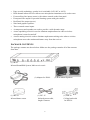
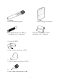
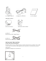
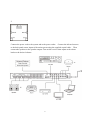
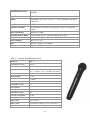
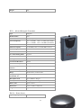
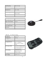
INFRARED SOUNDFIELD SYSTEM
IR-89
User Guide
Thank you for buying this product.
Please read through these operating instructions so you will know how to operate your
equipment properly. After you have finished reading the instructions, put them away in a
safety place for future reference.
TABLE OF CONTENTS
1.
SAFETY PRECAUTIONS………………………………………………2﹐3﹐4
2.
FEATURES………………………………………………………………5
3.
PACKAGE CONTENTS…………………………………………………5﹐6
4.
INSTALLING THE SYSTEM……………………………………………7﹐8
5.
IR-89 INFRARED SOUNDFIELD SYSTEM, MAIN RECEIVER
UNIT………………………………………………………………………9﹐10
6.
TRANSMITTER…………………………………………………………11﹐12
7.
CHARGER………………………………………………………………13
8.
TROUBLE SHOOTING…………………………………………………14
1
9.
DIMENSIONS……………………………………………………………14
10. GENERAL SPECIFICATIONS…………………………………………15
Thank you for your purchase of IR-89 Infrared Soundfield System. Before using the
equipment, be sure to read this entire operating manual so that you can take full advantage of
the IR-89's features. After you finish reading, keep this document and the warranty handy in a
safe place in case you need them in the future. The manual should be very helpful in
understanding the system and solving any difficulties that may arise during use.
SAFETY PRECAUTIONS
To ensure proper use of the equipment, carefully read the Safety Precautions prior to use.
Icon Labels
A variety of icon labels are used in these Safety Precautions section to ensure safe and proper
use of the product, to prevent injury to yourself and others, and to prevent property damage.
Make sure you fully understand the meanings of the icon labels as you read the manual.
Warning
This label is used in cases where there may be a possibility of death of serious injury if the
label is ignored and the equipment is used improperly.
Caution
The label is used in cases where there may be a possibility of injury or just physical damage
if the label is ignored and the equipment is used improperly.
a. A fire or electric shock may result if the equipment is used under abnormal conditions
(e.g., if it is emitting smoke, or strange odors or noises). In such cases, immediately
remove the power plug from the outlet. Make sure the equipment stops emitting smoke,
then contact your dealer to have it repaired.
b. If water enters the equipment, first turn off the equipments' power switch and remove the
power plug from the power outlet, then contact your dealer. Using the equipment under
such conditions may result in fire or electric shock.
c. If a foreign object enters the equipment, first turn off the equipment's power plug from the
power outlet, then contact your dealer. Using the equipment under such conditions may
result in fire or electric shock.
2
d. If you drop the receiver or damage its cabinet, remove the power plug from the power
outlet and contact our dealer. Using the equipment under such conditions may result in
fire or electric shock.
e. If the power cord is damaged (e.g., If the core wire is exposed or if the cord is broken),
have the cord replaced by the dealer. Using the equipment under such conditions may
result in fire and electric shock.
f. Do not use the equipment at voltages other than the supply voltage. Doing so may result
in a fire or electric shock.
g. When you install the equipment, leave a gap of at least 10cm between it and the nearest
well. Also make sure there is a bit of space between it and the other equipment to ensure
proper heat dissipation. If you install the equipment on a rack, make sure there is at least
2cm of free space above the unit, and at least 5cm behind it. If there is not enough free
space around the unit, heat may build up inside of it, possibly result in a fire.
h. Do not use the equipment near bathing areas. Doing so may result in fire or electric
shock.
i. If there is lightning near the equipment, do not touch its power plug. Doing so may result
in electric Shock.
j. Do not allow water to enter the equipment or allow it to get wet. Doing so may result in a
fire or electric shock. Be especially careful when using e equipment when it is raining or
snowing, and when using it near the ocean or other large bodies of water.
k. Do not set flower vases, plant pots, cups, cosmetics, medicines, or any container filled
with water or other liquids, or small pieces of metal, on top of the equipment. In such case,
fire or electric shock my result if the liquid spills on the equipment or metal enters it.
l. Do not set candles or other flame sources on top of the equipment. Doing so may result in
fire.
m. Do not attempt to charge dry cell batteries. Doing so may result in fire or injury if the
batteries burst or Leak.
n. Do not connect the equipment to a direct current (DC) power supply on ships or the like.
Doing so may result in fire.
o. Do not block the ventilation holes on this equipment. If the ventilation holes are blocked,
heat may build up inside the equipment, possible resulting in a fire. There are ventilation
holes on the top and bottom of the equipment's casing in order to prevent the internal
temperature from rising. Do not use the equipment in any of the following ways:
Do not set the equipment so that it faces upward, or set it on its side, or turn it upside
down.
Do not fit the equipment into a bookshelf (except for a special rack), closet or other space
with poor Ventilation.
Do not place a tablecloth, rug, or bedspread on top of the equipment and attempt to use
3
p.
q.
r.
s.
the equipment.
Do not set anything heavy on the power cord, or place the cord under the equipment.
Doing so may damage the cord, possibly resulting in a fire or electric shock. If the cord is
placed under a carpet or the like, somebody may not notice the cord and set something
heavy on top of it.
Do not insert or drop in anything metallic or flammable through the disc insertion slot on
the equipment.
Doing so may result in fire or electric shock. Be especially careful if there are small
children in our household.
Do not damage, modify, excessively bend, twist, or pull on the power cord. Doing so may
damage the cord, possibly resulting in a fire or electric shock.
Never remove the equipment's back lid, cabinet, or cover
The equipment contains high-voltage components which could cause electric shock if
touched.
Contact your dealer for internal checks, maintenance, and repairs.
t. Do not modify the equipment. Doing so may result in fire or electric shock.
Caution
a. Do not install the equipment in smoky or steamy locations, such as near kitchens or
humidifiers.
Doing so may result in fire or electric shock.
b. Do not install the equipment in an unstable location, such as a wobbly mount or on a
slanted surface.
The equipment may fall of or tip over if installed in such locations, resulting in injury
c. Do not place the power cord near a heater. In such cases, the cord sheathing may melt,
resulting in fire or electric shock.
d. Do not leave the equipment in a location that could become extremely hot, such as inside
an automobile when the windows closed or in a location exposed to direct sunlight. Doing
so may adversely affect the cabinet and components, possibly resulting in a fire.
e. Do not install the equipment in humid or dusty locations. Doing so may result in a fire or
electric shock.
f. When removing the power plug, do not pull on the power cord. Doing so may damage the
cord, resulting in fire or electric shock. Always grasp the plug as you remove it.
g. Do not move the system with equipment such as a television or audio equipment on top of
it. The system may tip over or fall off, possibly resulting in injury.
4
h. Do not climb on or hang from the equipment. The equipment may tip over or damaged,
possibly resulting in injury. The caution is especially important for children.
i. Do not set anything 5kg or heavier on top of the equipment. Also do not set anything on
the equipment which protrudes beyond the edges of the equipment. In such cases, a loss
of balance may cause the object to tip over or fall, possibly resulting in injury
j. Do not remove or insert the power or plug with wet hands. Doing so may result in electric
shock.
k. If you plan to connect audio equipment or other equipment to the system, carefully read
the operating manuals provided with that equipment. Turn off all equipment power and
connect the equipment according to the instructions in the manuals. Only use the
designated cords in connecting the equipment. Using cords other than those designated or
using extension cords may cause heat to build up, possibly resulting in burn injuries.
l. Before turning on the equipment, set the volume to the lowest setting. At a high volume
setting, the sudden loud output noise could damage your hearing.
m. If you are not going to be using the equipment for an extended length of time, remove the
batteries. Leaking batteries could cause fire, injury, or damage to the surrounding. If a
battery leak occurs, thoroughly wipe the fluid from the battery case, and then insert a new
battery. If battery fluid gets on you, thoroughly rinse it off with water.
n. To prevent accidents, install the equipment near a power outlet so that it can be unplugged
immediately.
o. Contact your dealer about once every five years to have the equipment's interior cleaned.
If dust builds up inside the equipment and it is not cleaned for an extended length of time,
fire or injury may result. Ask your dealer This type of cleaning is especially effective
prior to the rainy season, when humidity rises. for prices on leaning service.
p. If you are not going to be using the equipment for an extended length of time (e.g., if you
go traveling), be sure to remove the power plug from the outlet as a safety precaution.
Failure to do so may result in fire.
q. Before moving the equipment, turn off the power switch, and be sure to remove the
power plug from the outlet and disconnect any antennas and cords (such as cords
connecting different pieces of equipment). If this is not done, the cords may be damaged,
resulting in fire or electric shock.
r. Before cleaning the equipment, remove the power plug from the outlet as a safety
precaution.
FEATURES
◆
◆
◆
Main receiver unit can be free-standing or rack mountable with 1 3/4”rack space.
Four 25 watt amplifiers with eight speaker output connections.
Individual volume control for each amplifier output.
5
◆
◆
◆
◆
◆
◆
◆
◆
◆
◆
Page override technology, speaker level switchable (24V, 80V or 100V)
Dual channel infrared receiver allows two microphone transmitters to be used at once.
Four auxiliary line inputs (stereo) with volume control on the front panel.
Front panel line output for personal listening system with gain control.
Real Panel line output (stereo).
Nine band graphic equalizer.
Three external sensor inputs.
A compressor and expander are used to provide a wide dynamic range.
A tone squelching circuit it is used to eliminate unpleasant noise when a wireless
microphone is tuned on and off.
A noise muting circuit is used to eliminate unpleasant cracking noise when a wireless
microphone moves the maximum distance away from the receiver.
PACKAGE CONTENTS
The package contents are shown below. Make sure the package contains all of the contents
show here.
(1) IR-89
Infrared Soundfield System, Main receiver unit
(1) Adaptor for IR-89
(1) IRS-30
Infrared dome sensor
(1) ISC-15
Infrared sensor cable,
length-15meters
6
(2) Wall Mount Speakers
(1) ISH-30
Ceiling bracket kit
for IRS-30
(1) IRM-99
Infrared handheld microphone
(1) IRT-1
Infrared bodypack transmitter
(1) Rechargeable battery for IRM-99,
Ni-MH type 2.4V / 26500mAH
(2) Rechargeable battery for IRT-1,
Ni-MH type 1.2V / 2650mAH
Accessory for IRT-1
(1) LM-10 Lapel microphone for IRT-1.
or
(1) HM-20 Headset microphone for ITR-1
or
(1) PM-30 Plug in microphone for ITR-1
7
(1) Charger CHR-306
(1) Adaptor for CHR-306
(1) User Manual
Alternative sensors
(1) IRS-02
Infrared wall sensor
(1) ISH-02
Wall bracket kit for IRS-02
(1) ISC-05
Infrared sensor cable, length-5meters
(1) ISC-10
Infrared sensor cable, length-10meters
INSTALLING THE SYSTEM
System and Connection Diagram
Install the infrared sensors in high locations so that the infrared sensors will have line of sight
over the entire room and the emitter light from the transmitters is not blocked by people or
other objects.
Installation example(as seen from above)
1.
8
2
Connect the power cord to the system and to the power outlet. Connect the infrared sensors
to the back panel sensor inputs of the main system using the supplied coaxial cable. Then
connect the speakers to the speaker outputs. Turn on the receiver then adjust each volume
knobs to the desired volume.
9
INSTALLING THE INFRARED SENSOR
Attaching the infrared dome sensor
Installation 1
1. Screw the sensor into the bracket to attach it.
2. Attach the sensor bracket to the ceiling using the screw shown in the illustration.
3. Connect the sensor cable to the sensor and tighten securely.
4. The sensor better be installed horizontally face down to the floor.
Installation 2
1. Remove the ceiling tile and drill a hole about Ø 20 mm in it.
2. Push the screw through the ceiling tile and screw them into the ceiling censor by using the
two long screws (Ø 3x25mm) provided.
3. Connect the sensor cable to the sensor and tighten securely.
4. Return the ceiling tile and make sure everything is firm and steady.
Attaching the infrared wall sensor
1. Attach the sensor bracket to the wall using the screws shown in the illustration.
2. Slide the sensor into the bracket to attach it.
3. The sensor can be attached to the bracket from four different directions.
4. The sensor better be installed horizontally face down to the floor.
10
INFRARED SENSOR INSTRUCTION
Connection indicator
When the infrared sensor is plugged into
a sensor input jack, the indicator light
turns red. The connection indicator light
does not turn on if there is a connection
problem between the jack and the
connector, or if the cable is broken or
short - circuited. Therefore, if the indicator
light does not turn on, check the infrared
sensor connection, etc.
The sensor and sensor cable should be kept away
from CRT televisions, plasma televisions, fluorescent
lights, spotlights, neon lights, and the like. Doing so
may create noise, possibly damaging your speakers
or hearing.
11
Keep the sensor away from the special charger
CHR-306. If the sensor gets close to the
charger, noise can occur and may damage the
speakers or your hearing.
Caution:
1. Make sure the sensors are not installed behind anything.
2. Noise may occur if there are obstacles between the microphone and the sensors.
If you speak or sing loudly into the microphone while noise is occurring, the sound may be
interrupted.
3. Noise may occur if the infrared sensors are in the path of sunlight, spotlights, neon light,
and other bright light sources. Install the infrared sensors away from bright light sources.
4. Infrared light can pass through glass. Take this into consideration when installing the
infrared sensors if there is glass separating the installation room from adjacent rooms.
5. Make sure the attachment location is sufficiently strong before attaching an infrared sensor.
If the attachment is too weak or if the infrared sensor is improperly attached, it may fall
down. We assume no liability in the case of such accidents.
6. Noise may occur if you use infrared remote controls, infrared headphone transmitters,
plasma TVs or the special charger CHR-306 near the infrared sensor.
IR-89 INFRARED SOUNDFIELD SYSTEM, MAIN RECEIVER UNIT
Front Panel Diagram and Instruction
1.
2.
Power switch
The Power Switch turns the receiver on (-) and off (O). The red light next to the switch
indicates whether the unit is on (-).
CH A and CH B Wireless Microphone Volume Control
These control the relative volume levels of the two infrared wireless microphone
channels. If one of the microphones is too loud or soft relative to other sounds, adjust the
12
knob according. Rotating the knob clockwise increases the output level.
3. IR Indicators
The green signal light next to each knob indicates whether that channel is being
received.
4. Page Override
The yellow light indicates when the page is broadcast. When the school P.A. system
broadcasts an announcement, the signal from the P.A. system mutes the inputs to the
receiver and passes the page announcement signal through the receiver amplifier and to
the speakers.
5. Audio Input Volume
These input controls are conveniently located in the front of the unit for easy individual
sound sources volume adjustment.
COMPUTER: This controls the volume level of a COMPUTER audio signal connected to
the rear panel COMPUTER INPUT jack.
TV / VCR: This controls the volume level of a TV/VCR audio signal connected to the rear
panel TV/VCR INPUT jack.
CD / DVD: This controls the volume level of a CD/DVD audio signal connected to the rear
panel CD/DVD INPUT jack.
AUX: This controls the volume level of an auxiliary input signal connected to the rear
panel AUX INPUT jack.
6. Line Out
This Line output can be used to transmit the audio to another device, such as an
amplifier, a recorder or an assistive learning system.
7. Line Out ADJ
This controls the volume level of Line output.
Rear Panel Diagram and Instruction
8.
Speaker Level Controls
The four speaker output levels can be individually adjusted. The corresponding knobs
are located on the left to the connectors.
13
9.
Speaker Outputs (25W x 4, 4-8Ω)
The receiver has 4 speaker output terminals, each one driven by a separate power
amplifier (25W). These connectors are used to connect the cable from each speaker
(euro-block) to one of these euro-block speaker terminals. When connect 2speakers in a
terminal, use 8Ωspeakers to prevent amplifier burn down.
10. 9-Band Graphic Equalizer
The equalizer affects the output to the speakers and the line output. The sliding controls
adjust the levels of the various audio frequencies. This allows the installer to adjust the
overall tone of the sound coming through the speakers and to make the whole system
achieve optimum sound quality.
11. Page Input
Use cable to connect the school PA system to the PAGE INPUT of the receiver in the
rear panel. When the school P.A. system broadcasts an announcement, the signal from
the P.A. system mutes the inputs to the receiver and passes the page announcement
signal through the receiver amplifier and to the speakers. Four different kinds of page
input selectors. The knob on top of the page input controls the volume level of incoming
page.
12. Line Output
This Line output can be used to transmit the audio to another device, such as an
amplifier, a recorder or an assistive learning system.
13. Audio Inputs (RCA connector)
AUX: Receive stereo signal from any auxiliary device.
CD / DVD: Receive stereo signal from CD/DVD device.
TV / VCR: Receive stereo signal from TV/VCR device.
COMPUTER: Receive stereo signal from COMPUTER device.
14. Sensor Inputs (RCA connector)
There are 3 inputs for infrared sensors on the back of the receiver. The sensors are
connected to the receiver via coaxial cable with F type connectors. At lease one sensor
must be connected for the infrared receiver to function. Connected additional sensors
improve reception and cover lager space. When the sensor is connected to the receiver
and the receiver in turned on, the red light on the sensor will illuminate, indicating that
the sensor is active.
15. DC IN (19V)
Plug the DC19V, 4.75A power supply into this jack.
14
TRANSMITTERS
Handheld Microphone IRM-99 Diagram and Instruction
Rechargeable battery Ni-MH type 2.4V / 2650mAH x1
1. On / Off Switch
2. Indicator Light
on=Green
red=Battery Low
3. Channel Selector
4. Battery Compartment
5. Emitter Diodes (Do not block)
6. Battery Compartment Tube Cover
7. Cartridge and Steel Mesh
8. Ring
Access Microphone Battery
Step1: Unscrew the cover from the lower half of the microphone.
Step2: Insert battery with (+)contact toward the bottom side. Be aware of the (+)(-) battery
15
polarity.
Step3: Screw the cover back to the microphone compartment tube.
Operating
1. Turn on the main unit of the infrared teaching amplifier system and the other equipment.
*The system will not receive any signal for approximately 5 seconds after the power is
turned on.
2. Remove the battery compartment tube cover and set the channel to the desire one.
3. Turn on the microphones.
When the microphone is turn on, the green power indicator light should be illuminated.
If the battery is low, this indicator light will turn to red.
*Do not block emitter diodes with hand.
*Bring the microphone close to one of the infrared sensors and make sure the infrared
sensor picks up the microphone signal. (Do this while making sure that the other
infrared sensor cannot receive the signals.)
If the sensor does not receive the microphone's signal, or if the sensitivity is poor, check
the cable connection.
Bodypack IRT-1 Diagram and Instruction
Rechargeable battery Ni-MH type 1.2V / 2650mAH x2
1. On / Off Switch
16
2.
3.
4.
5.
Volume Control
Power Indicator
Microphone Input
Emitter diodes
(Do not block)
6. High / Low Power
Output Selector
7. Channel Selector
8. Battery Compartment
9. Wire Clip
10. Charging Contacts
Access Microphone Battery
Step1: Open battery cover.
Step2: Insert batteries into the compartment and follow polarity indicators. Be aware of the
(+)(-) battery polarity.
Step3: Step3: Close battery cover.
Operating
1. Turn on the main unit of the infrared teaching amplifier system and the other equipment.
*The system will not receive any signal for approximately 5 seconds after the power is
turned on.
2. Remove the IRT-1 battery compartment cover and set the channel to the desire one.
3. Plug in the microphone to the transmitter and adjust the microphone distance as close to
mouth as possible.
4. Turn on the microphone transmitter and adjust the volume level.
When the microphone is turn on, the green power indicator light should be illuminated.
If the battery is low, this indicator light will turn to orange.
*Do not block emitter diodes with hand.
*Bring the microphone transmitter close to one of the infrared sensors and make sure the
infrared sensor picks up the microphone signal. (Do this while making sure that the
other infrared sensor cannot receive the signals.)
If the sensor does not receive the microphone's signal, or if the sensitivity is poor, check
the cable connection.
17
CHARGER
Diagram and Instruction
Top View
Bottom View
1.
2.
3.
4.
5.
6.
7.
8.
9.
10.
Side View
D slots charging and saturated indicator light
D slots discharging indicator light
C slot charging and saturated indicator light
D slot discharging and enforced charging switch
B slot discharging and enforced charging switch
A slot charging and saturated indicator light
B slot discharging indicator light
B slot charging and saturated indicator light
Microphone support jack
C slot charging area
( for handheld microphone use only )
18
11. B slot charging area
(for rechargeable batteries and bodypack transmitter)
12. A slot charging area
(for handheld microphone use only )
13. D slot charging area
(for rechargeable batteries and bodypack transmitter)
14. DC12V input
15. Switch for saturated alarm
Charging
TROUBLESHOOTING
If you think there may be a problem with the equipment, perform the troubleshooting checks
shown below. Sometimes an unexpected error makes it seem like the equipment is broken.
If you are still unable to solve the problem after performing these checks, contact your dealer.
Phenomenon 1: No sound
Check
The wireless microphone
battery is dead.
The microphone tone
frequency does not
match.
The system and amp
speakers are not properly
connected.
Solution
Charge or replace the
microphone battery
Use microphones with
the same tone
Check the connection.
19
frequency.
Phenomenon 2: Low volume
Check
The system's volume adjustment is
too low.
The speakers' output power is not enough.
Solution
Turn the volume adjustment knob
clockwise
to set the desire volume.
Connect an additional speaker to the
speaker terminal.
Phenomenon 3: Poor reception sensitivity and Hearing static
Check
Solution
The infrared
sensor cable is
not properly
connected.
The infrared
sensor is not
installed in
optimum
location or
hidden.
You are
holding the
Properly
connect the
infrared
sensor cable.
Attach the
infrared sensor
in a position
with line of
sigh.
Hold the
microphone
properly.
microphone's
infrared
light emitters
Is the mute
sensitivity
set to
"LOW"?
Two
microphone
transmitters
Set the mute
sensitivity
switch to
"HIGH".
Ensure
microphone
transmitters
are operating
on different
channel
are operating
on the same
channel
simultaneously
Notes:
1. Noise or hearing static may occur if the infrared sensors are in the path of sunlight or
other bright light sources, or if they are blocked by something. Noise in such cases is a
natural occurrence due to the way the infrared sensors work. It does not indicate any
problem with the equipment.
2. Noise or hearing static may occur when you disconnect and then connect an infrared
sensor while a signal is being received.
3. Noise or hearing static may occur if you turn the power on and off while a signal is
being received.
20
DIMENSIONS
UNIT:CM
GENERAL SPECIFICATIONS
IR-89
Infrared Soundfield System
Receiving Method
Infrared Receiving
No. of Channel
2
Frequency
Ch A : 2.08 MHz / Ch B : 2.54 MHz
Infrared Wavelength
850 nm
Modulation
FM wide-band
De-emphasis
50μS
Frequency Response
50Hz ~ 15KHz
S/N Ratio
> 65dB
THD
<1%@1KHz
Nominal Deviation
±10KHz
21
Maximum Deviation
±25KHz
Input Level
1V / 1KΩ
Input
4 terminals, AUX, CD / DVD, TV / VCR, computers with RCA
connectors
Amplifier Output
100W
Speaker Terminal
Terminal Block connectors, 8Ω speaker x 8pcs or 4Ω speaker
x 4pcs
Receiving Range
20m line-of-sight
External Sensor Input
Could connect up to 3 external sensors, RCA type.
Output
1(front) 3.5mm phone jack, 1(rear) RCA connector
Power Supply
DC 19V / 4.75A
Size
429(W) × 42(H) × 181(D)mm
Weight
Approx. 1.38kgs
IRM-99
Infrared Handheld Microphone
Model No.
IRM-99
Transmission Carrier
Infrared
Modulation
FM
Carrier Frequency
Ch A : 2.08 MHz Ch B : 2.54 MHz (Switchable)
Ch C : 2.30 MHz Ch D : 2.80 MHz (Switchable)
Pilotone Frequency
32.768 KHz (A.B ch.) or 38.000 KHz (C.D ch.)
IR Wavelength
850 nm
Peak Deviation
± 25KHZ
No. of IR emitting Diode
10 pieces
Compander Circuit
Yes
Pre-emphasis
50μS
Location of IR Emitter
Built-in
Transmission Angle
360°
Current Consumption
330 mA
Microphone used
Unidirectional Dynamic
Battery Life
approx. 6 hours
Battery Used
Rechargeable NI-MH type 2.4V / 2650 mAH x 1
Dimensions
247(L) x 45(dim.) mm
22
250g
Weight
IRT-1
Infrared Bodypack Transmitter
Type
Bodypack
Model number
IRT-1
Transmission Carrier
Infrared Ray
Carrier Frequency
Ch A : 2.08 MHz Ch B : 2.54 MHz (Switchable)
Ch C : 2.30 MHz Ch D : 2.80 MHz (Switchable)
Modulation
FM
Pilotone Frequency
32.768 KHz(A.B ch.) or 38.000 KHz (C.D ch.)
IR Wavelength
850 nm
Peak Deviation
± 25KHZ
No. of IR emitting Diode
10 pieces
Compander Circuit
Yes
Pre-emphasis
50μS
Location of IR Emitter
Built-in
Transmission Angle
360°
IR Power Output
selection
HI (Hight) LO (Low)
Current Consumption
HI-400 mA, LO-330 mA
Range
HI about 30m , LO about 20m
Microphone input
Socket(MIC IN)
3.5 mm mono phone jack
Microphone used
Lapel / Headset / Plug-in
Battery Used
Rechargeable NI-MH type 1.2V / 2650 mAH x 2
Battery Life
approx. 7 hours
Dimensions
110(L) x 63(W) x 20(H) mm
Weight
78g
IRS-30
Dome Sensor
Operating frequency
2MHz to 2.6MHz
23
Operating range
20m line-of-sight
Signal / Power interface
RCA type
Number of IR LED
30
Reception area
232m / 2500ft
Power indicator LED
Red
Reception angle
360°full semi-spherical(half
dome) coverage
Dimensions
33(DIA) x 39(H) mm
Weight
160g
Operating frequency
2MHz to 2.6MHz
Operating range
20m line-of-sight
Signal / Power interface
RCA type
Number of IR LED
15
Reception angle
120°horizontally / 120°vertically
Power indicator LED
Red
Dimensions
65(DIA) x 29(H) mm
Weight
35g (without Cable)
CHR-306
3 in 1 Drop-in Charger
Charging Slot
A/B/C/D
Charging Mode
Switching
Charging Current
800mA ±10%
Discharging current
350mA
Charging Indicators
Red = Charging, Green = Full,
Yellow = Discharging,
Blinking Orange = Charging
Standby
Switchable Discharging(yellow)
/ Charging(red) button for B and
D slots (use for Bodypack or
rechargeable battery)
Automatically switch to
charge(red) mode when
discharge Complete
Discharging Method
Auto Switching
Charging Time
3~4hr/ slot
Power Supply
DC 12V / 1.2A
24
Dimensions
165(L) x 85(W) x 35(H)mm
Weight
320g (with microphone holders
and adapter)
Please record your system serial numbers. This information is helpful when ordering
additional components, accessories, and requesting warranty service.
25
26