1
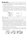
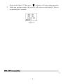
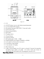
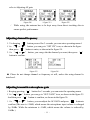
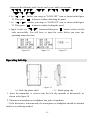
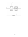
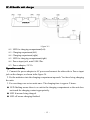
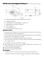
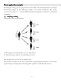
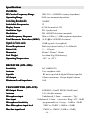
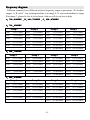
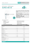
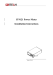
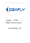
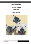
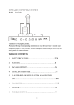
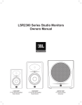
SPL-32R/SPL-32T
UHF Wireless Tour Guide System
User Manual
SPL-32T
SPL-32R
SOOLAI ELECTRONICS CO.,LTD
Thank you for choosing SOOLAI!
Please take a few moments to read these instructions carefully, as we want you to
enjoy your new SOOLAI products quickly and to the fullest.
Special features
●Super mini, light weight, metal shell and five colors for choice
●UHF professionaly frequency, PLL synthesized design, 32 channels available
●16 digital ID pilotone design to avoid the background noise
●High performance double-IF circuit design to enforce RF level
● 96*64 dot matrix White LCD display
● LCD display Channel, frequency, volume, battery, RF level, AF level, transmitter
gain, RF power, and lock. Mode
● Transmitter dynamic display of AF level, AF Over load warning, 31-step
microphone gain adjustment design
●Quick-mute function
●Receiver digital 16-step volume control
●Receiver digital 21-step SQ adjusting
●Locking protection of panel operation with security codes
●Inputting Lithium-ion battery working for 9-11 hours
●Two ways of attaching belt clips: downwards and upwards
●3.5mm input jack for inputting background music, CD, MP3, etc
●Transmitting range 300 ft (line-of-sight)
Main Applications
Applications:
Simultaneous interpretation
International conference simultaneous interpretation
Touring
Widely used in touring, visiting museums, exhibitions
Guest reception
Used in reception of visitants in product presentation, advanced exhibition of large
companies
Teaching
Used in meeting and teaching of school and so on
Stage monitoring
Monitoring of performance: especially for acting singer to monitor accompaniment
- 2 -
CONTENT
.... 04
SPL-32R receiver ……………
……………..………………………………………
………………………………………....
...
…………………………… 05
Operating controls ………………………
………………………...
...……………………………
..
………
.. 06
Adjusting channel/frequency …………
…………..
..………
………..……………………
……………………..
..
……
.. 06
Adjusting the squelch threshold…………
…………..
..……
……..………………………
………………………..
Setting locking/unlocking …………
…………..……………………………………
…………………………………….. 07
.. 08
Exiting from setting operation……………
……………..……………………………
……………………………..
..
…………………………
.. 09
SPL-32T transmitter ………………………
………………………..
..…………………………
…………………………..
..
……………………
Operating controls…………………………
…………………………..
..……………………
……………………..……
…….. 10
..
………………………
.. 11
Adjusting channel/frequency …………………
…………………..
..………………………
………………………..
..
……………
.. 11
Adjusting microphone gain………………………………
………………………………..
..……………
……………..
..
…………………
.. 12
Adjusting transmitting power………………………
………………………..
..…………………
…………………..
Setting locking/unlocking .………………………………………………
……………………………………………….. 13
..
…………
.. 13
Operating belt clip …………………………………………
…………………………………………..
..…………
…………..
......
........................................
......... 15
SC-02 two unit charger………………
………………......
..............................................
.................................................
..
………
.. 16
SCB-20 twenty unit charging and storing case …………………
…………………..
..………
………..
………………………………………………………………
.17
Application samples
samples………………………………………………………………
……………………………………………………………….17
19
Troubleshooting ……………………………………………………………………
……………………………………………………………………19
……………
specifications………………………………………
………………………………………......……………
……………..………
……….. 20
…………………………
.........
frequency diagram………………
………………......…………………………
………………………….........
....................... 21
- 3 -
Receiver (SPL-32R)
SPL-32R
LCD
(figure 1)
(1). LCD
(2). On/Off button (keeping it pressed for 3 seconds will switch the receiver on)
(3). Tie pillar or 1/4 wavelength flexible antenna
(4). 3.5 mm jack socket for headphones
(5). Rocker button (UP)
(6). Rocker button (DOWN)
(7). SET button
(8). Charging contact
(9). Channel display
(10).Frequency display
(11). 16-step headphone output volume display
(12). 6-step dynamic RF display
(13).Lock mode icon (lock mode is activated)
(14). 4-step battery status display
(15). 6-setp dynamic AF display
(16). Audio overload display, ‘OL’ means transmitter microphone input volume is too
high. It needs to be reduced (adjusting transmitter AF gain until there is no OL
on display)
- 4 -
Operating controls
1. Via keeping ON/OFF button pressed for 3 seconds, you can switch the receiver on.
2. Via pressing UP or DOWN button, you can add or reduce headphone volume.(The
minimum is 1, and the max is 16.)
3. Via keeping ON/OFF button pressed for 3 seconds, you can switch the receiver off.
4. Via keeping SET button pressed for 3 seconds, you can enter the operating manu,
as shown in the figure 2. If there is no operating manu, you will see the code
inputting picture, as shown in the figure 3. It means the former user has set the lock
mode. You have to input the code, if you want to enter. Please refer to (Setting
Locking/unlocking )
(figure 2)
(figure 3)
●If you can not switch the receiver on, it means the battery is flat. You have to charge
before open it again.
● The receiver will switch off automatcially when the battery is flat to protect the
lithium-ion battery. Please do not open before you have charged the battery.
● While the transmitter being off, please check the RF on display of receiver. If there
is no RF volume display, it means there is no frequency interference. You can use
this channel, as shown in the figure 4. If there is RF volume display, it means the
frequency is interfered. Please change to another channel so that it is not interfered,
as shown in the figure 5.(Please refer to adjusting channel/frequency )If there is
AF volum on display, it means the receiver has received signal from one transmitter
which is swtiched on (as shown in the figure 6).
● Listening at high volume levels for long periods can lead to permanent hearing
defects. Set the volume for the connected headphones to the minimum before
putting the headphones on.
- 5 -
figure 4
figure 5
figure 6
Adjusting channel/frequency
1. Keeping SET button pressed for 3 seconds, you can enter the operating manu.
2. Via “ ”o r“ ” button, you can select “SET CH” icon, as shown in the figure 7.
Then press SET button to enter, as shown in the figure 8.
3. Via“ ”or“ ” button, you can go to the channel you want and then press “ ”
botton. The channel is stored.
(figure 7)
(figure 8)
※ While adjusting the channel, if there is RF display, it means there is interference.
Please change to another to ensure perfect performance.
Adjusting the squelch threshold
1. Via keeping SET “ ”button pressed for 3 seconds, you can enter the operating
manu.
2. Via“ ”o “
r
”button, you can select “SET SQ” icon, as shown in the figure 9. Then
press “ ” button to enter, as shown in the figure 10.
3. Via“ ”or“ ” button, you can adjust the SQ volume, then press “ ” button to
store the setting.
※ While the transmitter being off, if there is RF volume on display of receiver, it
means the receiver is interfered by background noise. Please adjust to another
channel or add the SQ volume. For adding the SQ volume, the transmitting range
will become shorter. The more the SQ is, the shorter the transmitter range becomes.
(The minimum SQ is -10, while the max is +10).
- 6 -
(figure 9)
(figure 10)
Setting locking / unlocking
1. Keeping “ ” button pressed for 3 seconds, you can enter the operating manu.
※ If there is no operating manu but “CODE?---” displays, it means the former user
has set locking code, as shown in the figure . You have to enter the correct code via
“ ”o “
r
” button. Then press “ ” button to continue. If you enter wrong codes,
there will be “INVALID” on the display. Please enter the correct code. If the code
is lost, you can try enterring the following total 8 codes one by one, until you can
enter successfully. “
”、“
”、“
”、“
”、“
”、“
2. Via“
”o “
r
”、“
”、“
”.
” button, you can go to the “LOCK OFF” icon and press “ ” button
to unlock the panel operating, as shown in the figure 11.
”o“
r
” button, you can go to “LOCK ON” icon and then press“ ” button,
3. Via“
as shown in the figure 12. You will need to enter 3 codes, as shown in the figure 13.
4. Via “ ”o r“ ” button, you can enter 3 codes. Then press “ ” button to store t he
operating. Next time you have to enter the 3 codes before you can enter the
operating manu successfully..
(figure 11)
(figure 12)
(figure 13)
Exiting from setting operation
1. In the operating manu, you can go to “EXIT” icon via “ ”o r“ ” button, as
- 7 -
shown in the figure 14. Then press “ ” button to exit from setting operation.
2. Under any operation status, the receiver will return to start display if there is
no operating for 5 seconds.
(figure 14)
SPL-32T transmitter
- 8 -
SPL-32T
LCD
(figure 15)
(17). LCD
(18). ON/OFF button, (serve as mute button in operating manu)
(19). 1/4 wavelenth flexible antenna
(20). Microphone/line input (MIC/LINE), 3.5 mm jack socket
(21). Rocker button (UP)
(22). Rocker button (DOWN)
(23). SET button
(24). Charging contact
(25). Channel display
(26). Frequency display
(27). Microphone gain (-10dB----+20dB)
(28). Transmitting RF power display (NORMAL or HIGH)
(29). Lock mode icon (Lock mode is activated.)
(30). 4-step battery status display
(31). 6-step dynamic AF display
(32). Mute display icon
(33). Audio overload display icon (OL status is activated.) It means the transmitter
microphone input volume is too high . You need to reduce the volume via
adjusting the AF GAIN until the OL icon disappears from the LCD.
Operating controls
- 9 -
1. Via keeping “ ” button pressed for 3 seconds, you can switch the transmitter on,
as shown in the figure 16.
2.“ ”button serves as mute button in operating manu. You can switch by pressing the
button between mute mode and no mute. It is in mute mode, as shown in the figure
17
(figure 16)
(figure 17)
3. Via keeping pressing ON/OFF button for 3 seconds, you can switch the transmitter
off.
4. Via keeping pressing “ ” button for 3 seconds, you can enter the operating manu,
as shown in the figure 18. If the “CODE?---” appears, as shown in the figure 19, you
have to enter the correct three codes. Please refer to Setting locking / unlocking.
(figure 18)
(figure 19)
● If you can not switch the receiver on, it means the battery is flat. You have to charge
●
●
●
●
●
before open it again.
The receiver will switch off automatcially when the battery is flat to protect the
lithium-ion battery. Please do not open before you have charged the battery.
Before using, please insert the microphone to Microphone/line input (MIC/LINE),
3.5 mm jack socket.
While using, please do not pull out the microphone.
Please put headmicrophone or lavalier microphone as close as to speaker’s mouth to
get perfect performance.
In normal speaking volume, if AF display 1-2 steps, it means transmitter
microphone input volume it too low, as shown in the figure 20, which needs to be
adjusted higher via adjusting transmitter AF GAIN. If it is 4-5 steps, it means
perfect performance. If there is OL icon, you have to adjust AF GAIN lower. Please
- 10 -
refer to Adjusting AF gain.
(figure 20)
※
(figure 21)
(figure 22)
While using, the antenna has to be kept away from direct touching skin to
ensure perfect performance.
Adjusting channel/frequency
1. Via keeping “ ” button pressed for 3 seconds, you can enter operating manu 2
2. Via “ ”or“ ” button, you can go to “SET CH” icon, as shown in the figure
then press “ ” button to enter, as shown in the figure 24.
3. Via “ ”or“ ” button, you can go the the channel you want, then press “ ”
button to confirm.
(figure 23)
(figure 24)
● Please do not change channel or frequency at will, unless the using channel is
interfered.
Adjusting transmitter microphone gain
1. Keeping pressing “ ” button for 3 seconds, you can enter the operating manu.
2. Via“
”o “
r
” button, you can go to “SET GAIN” icon, as shown in the figure 25.
And then press “ ” button to confirm, as shown in the figure 26.
3. Via “ ”or“ ” button, you can adjust the AF GAIN and press “ ” button to
confirm.(The max is +20dB, which means the microphone input volume is enlarged
by 20dBs. While the minimum is -10dB, which means the volume is reduced by
10dBs.)
- 11 -
● The user can adjust the AF GAIN according to AF dynamic volume display. If OL
appears, please reduce AF gain. If AF display 1-2 steps, you need to add AF gain.
Generally, 4-5 steps is the best performance.
(figure 25)
(figure 26)
● While using head microphone, the reference range is 0dB---5dB.
● While using lavalier microphone, the reference range is +13---+18dB.
※ In noisy background, you are suggested to use head microphone to get perfect
performance.
Adjusting transmitting RF power
1. Keeping pressing “ ” button for 3 seconds, you can enter operating manu.
2. Via “ ”o r“ ” button, you can go to “SET PWR” icon, as shown in the figure 27.
And press “ ” button to confirm, as shown in the figure 28 or 29.
3. If you select “HIGH” icon, it means you select higher transmiting power---20mW.
4. If you select “NORMAL” icon, it means you select normal transmiting power--10mW.
(figure 27)
(figure 28)
(figure 29)
Setting locking / unlocking
1. keeping pressing “ ” button for 3 seconds, you will enter operating manu.
● If there is no operating manu, but “CODE?---” icon, it means the former user has
set code. You need to input the code and press “ ” button to confirm. If the code
is wrong, “INVALID” will appear. Please try other codes. If the code is lost,
- 12 -
please try the following total 8 codes one by one, until you can enter.
“
”、“
“
”、“
”、“
2. Via “
”o r“
”、“
”、“
”、“
”、
”.
” button, you can go to “LOCK OFF” icon, as shown in the figure
30. Then press “ ” button to confirm unlocking the panel.
3. Via “ ”o r“ ” button, you can go to “LOCK ON” icon, as shown in the figure
31. Then press “ ” button to confirm locking the panel.
4 . Input 3 codes via “ ”o “
r
” button and then press “ ” button. ou have set t he
code successfully. You will have to input the codes before you enter the
operating manu next time.
(figure 30)
(figure 31)
(figure 32)
Operating belt clip
(figure 33)
(34)Belt clip plastic shell
( 35)Metal spring clip
1. Insert the transmitter or receiver into the belt clip upwards or downwards, as
shown in the figure 34.
2. Then insert microphone or headphone into jacks of machines.
※If the direction is in downwards, the microphone or headphone should be attached
finally to avoid being crashed.
- 13 -
(figure 34)
- 14 -
SC-02double unit charger
(figure 36)
(42)LED for charging compartment(left)
(43)Charging cmpartment(left)
(44)Charging cmpartment(right)
(45)LED for charging compartment(right)
(46)Power input jack, mini USB 5Pin.
(47)Power adapter, 5V/1A
Operation controls
controls:
1. Connect the power adapter to AC power and connect the other side to Power input
jack on the charger, as shown in the figure 36.
2. Put the mahcines into the charging compartment upwards. You have being charging
the units.
3. You can charge one or two units once. The charging time is approx 2 hours.
● LED flashing means there is no unit in the charging compartment or the unit does
not touch the charging contact appropriately.
● LED lit means being charged.
● LED off means charging finished.
- 15 -
SCB-20 twenty unit charging and storing case
(figure 37)
(48)charging compartment/storing compartment, 20 totally
(49)storing compartment
(50)compartment for storing headphone, earphone, etc
(51)compartment for storing Power adapter
(52)Power input jack
(53)Power adapter, 5V/3A
(54)Car power adapter connecter SA-503
Operation controls
controls:
1. Connect the power adapter to AC power and connect the other side to Power input
jack on the charger, as shown in the figure 37.
2. You can connect input jack of SA-503 to cigarette-lighter Plug on car. And connect
the other side to Power input jack of SCB-20.
3. Put the units into the charging compartment upwards to charge.
4. You can charge the units from 1-20 units at the same time once and the charging
time is approx. 4 hours.
5. You can put total 40 units in SCB-20 for storage.
● LED flashing means no units in the charging compartment or the unit does not
touch the charging contact appropriately.
● LED lit means units being charged.
● LED off means units charging finished.
Pay attentions:
①Do not close the case when you charge the units with enforcing antenna.
②Do not store the units in charing compartment which have enforcing antenna.
- 16 -
Main application samples
In trialogue setting, you are proposed to use the units with enforcing antenna to enlarge
transmitting range. In the following samples, TX means transmitter. RX means
receiver. (A), (B), (C)……means different channels/frequencies: channel A, channel B,
channel C……
tourjing, visiting
A.tourjing,
One speaker with many listeners.
1. The speaker can transmit his voice via transmitter.
2. Other listenners can hear via attaching receivers.
The number of receivers can be added at will.
The speaker can take one EL-60 extend linker to input background music. It will make
your touring or visiting more interesting.(The speaker can also hear the music.)
- 17 -
Simultaneous Interpretation
B.Simultaneous
1. The speaker takes one transmitter set on non-interfence channel(TX A) and one
microophone.
2. Mother language listeners take receivers set on the same channnel(RX A) as the
transmitter’s so that they can hear what the speaker is saying.
3. Interpreters take receivers(RX A) for hearing the mother language and transmit
their interpreted languages to other language listenners via attaching transmitters
(TX B, TX C ……)
4. Other language listenners can hear the interpreters’ voice via the their receivers RX
B, RX C …… that are set on the same channel as that of cooresponding
interpreters’.
Pay attentions:
While using multiple channels, please select channels without interence between each
other.
If one takes both one receiver for listenning and one transmitter to interprete what he
hears to another language, he needs to make the distance between the receiver and the
transmitter as far as possible to avoid being interfered.
Please try the following solution if there is still interference. Set the channel into
- 18 -
different frequency ranges, such as range A and range B.(You have to contact SOOLAI
to preset the channel frequency for you!!!)(Please refer to Frequency diagram on page
21.)
Troubleshooting
No voice in receiver output
1. Make sure the transmitter and receiver are both powered.
2. Make sure the transmitter and the receiver are on the same channel frequency.
3. Make sure the microphone and earphone are attached appropriately.
4. Make sure the transmitter is not in Mute mode
5. Make sure the volume control on receiver is not adjusted on the minimum.
Short working distance
1. Make sure the antenna is not broken.
2. Make sure the transmitter is not close to other transmitter powers. In simultaneous
interpretation, make sure the interpreter’s transmitter and receiver are not on the
same channel frequency.
3. Try to set receiver’s SQ to “MIN -10” to check the effect.
4. Try to use another channel.
5. Check line of sight transmitting range.
Voice distortion
1. Make sure that there is no other transmitter using the same channel.
2. While using multiple channels, make sure there is no interference between each
other.
3. Make sure the transmitter’s microphone GAIN is adjusted to the best volume.
4. Try to adjust the receiver’s SQ to “MAX +10” to check the effect.
Too low voice
1. Make sure the transmitter’s microophone GAIN is adjusted at the best volume.
2. Make sure the receiver’s volume is adjusted at the best volume.
3. Replace the earphone to check the effect.
If still operating problems with your transmission installation occur, please contact
your local SOOLAI agent for assistance.
- 19 -
Specifications
SYSTEM:
RF Carrier Frequency Range
Operating Range
Switching Bandwidth
Switchable Frequencies
Display Screen
Oscillation Type
Modulation
Audio Frequency Response
Total Harmonic Distortion (1KHZ
(1KHZ))
Signal-to-Noise ratio
Power Requirement
Batter Life
Dimension
Unit Weight
Operating Temperature
UHF 518~865MHZ (country dependent )
300ft (environment dependent)
20MHZ
32
96*64 dot matrix LCD
PLL Synthesized
FM ±45KHZ deviation (nominal)
50hz to 15khz (+/-3dB);earphone dependent
<0.8% (Ref.±45KHZ deviation)
80dB typical (A-weighted )
Built-in polymer battery 3.6v/450mAh
9 ~11 hours
69mm * 42mm * 14mm
less than 50g (With battery)
-10℃ to +55℃
RECEIVER (SPL-32R):
Sensitivity
Antenna
Squelch
AF Output
Minimum Load Impedance
2uV (60dB S/N)
Uses earphone cable
RF noise squelch & digital Pilotone squelch
100mw maximum ,16setps digital volume
16Ω
TRANSMITTER (SPL-32T):
RF Output Power
Antenna
Microphone input
Line input
Microphone Sensitivity
Max Microphone input level
Max line input level
NORMAL=10mW HIGH=20mW(max)
1/4 λ flexible antenna
Unbalanced, 3.5mm connector(Tip)
Unbalanced, 3.5mm connector(Ring)ATT -10dB
programmable in 31 steps , -10dB to +20dB
7dBV to -22dBV (-10dB to +20dB)
17dBV to -12dBV (-10dB to +20dB)
- 20 -
Frequency diagram
Different countries have different wireless frequency range requirements. We do three
ranges: A, B, and C. Our existing machine is in range A. If you need machine in range
B or range C, please be free to let us know. And we will do our best to help.
790
810MHZ 、B
B:690
690
710MHZ 、C
C:850
850
870MHZ
A:790
790~810MHZ
690~710MHZ
850~870MHZ
790
820MHZ
A:790
790~820MHZ
Group 1
Group 2
Group 3
Group 4
CH2
790.875MHZ
CH3
791.500MHZ
CH1
790.250MHZ
CH2
790.875MHZ
CH7
794.000MHZ
CH8
794.625MHZ
CH4
792.125MHZ
CH5
792.750MHZ
CH15 799.000MHZ
CH16 799.625MHZ
CH10 795.875MHZ
CH11 796.500MHZ
CH25 805.250MHZ
CH27 806.500MHZ
CH16 799.625MHZ
CH17 800.250MHZ
CH31 809.000MHZ
CH31 809.000MHZ
CH23 804.000MHZ
CH24 804.625MHZ
CH31 809.000MHZ
CH32 809.625MHZ
Group 3
Group 4
690
720MHZ
B:690
690~720MHZ
Group 1
Group 2
CH2
695.875MHZ
CH3
696.500MHZ
CH1
695.250MHZ
CH2
695.875MHZ
CH7
699.000MHZ
CH8
699.625MHZ
CH4
697.125MHZ
CH5
697.750MHZ
CH15 704.000MHZ
CH16 704.625MHZ
CH10 700.875MHZ
CH11 701.500MHZ
CH25 710.875MHZ
CH27 711.500MHZ
CH16 704.625MHZ
CH17 705.250MHZ
CH31 714.000MHZ
CH31 714.000MHZ
CH23 709.000MHZ
CH24 709.625MHZ
CH31 714.000MHZ
CH32 714.625MHZ
Group 3
Group 4
840
870MHZ
C:840
840~870MHZ
Group 1
Group 2
CH2
850.875MHZ
CH3
851.500MHZ
CH1
850.250MHZ
CH2
850.875MHZ
CH7
854.000MHZ
CH8
854.625MHZ
CH4
852.125MHZ
CH5
852.750MHZ
CH15 859.000MHZ
CH16 859.625MHZ
CH10 855.875MHZ
CH11 856.500MHZ
CH25 865.875MHZ
CH27 866.500MHZ
CH16 859.625MHZ
CH17 860.250MHZ
CH31 869.000MHZ
CH31 869.000MHZ
CH23 864.000MHZ
CH24 864.625MHZ
CH31 869.000MHZ
CH32 869.625MHZ
- 21 -
SOOLAI ELECTRONICS CO.,LTD
Add: Xishanqiao, Yuhuatai Zone, Nanjing, 210041, China
Tel : 86-25-52803489
Fax: 86-25-84083635
E-mail:[email protected]
http://www.soolai.com
- 22 -