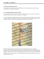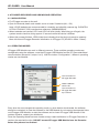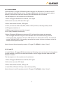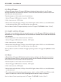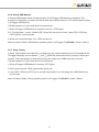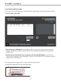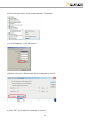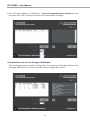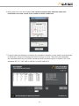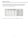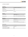
1
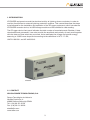
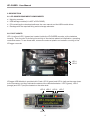
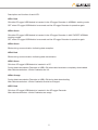
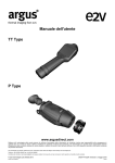
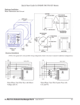
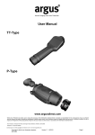
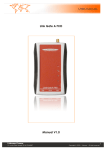
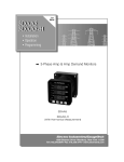
LIGHTNING
AIR TERMINALS
ATLOGGER EQUIPMENT
User manual
www.at3w.com
ATLOGGER · User Manual
INDEX
1.
INTRODUCTION . . . . . . . . . . . . . . . . . . . . . . . . . . . . . . . . . . . . . . 3
1.1.
CONTACT . . . . . . . . . . . . . . . . . . . . . . . . . . . . . . . . . . . . . . . . . . . 3
2.
DESCRIPTION . . . . . . . . . . . . . . . . . . . . . . . . . . . . . . . . . . . . . . . . 4
2.1.
ATLOGGER EQUIPMENT COMPONENTS . . . . . . . . . . . . . . . . . . 4
2.2.
PILOT LIGHTS . . . . . . . . . . . . . . . . . . . . . . . . . . . . . . . . . . . . . . . . 4
3.
INSTALLATION INSTRUCTIONS . . . . . . . . . . . . . . . . . . . . . . . . . . 6
3.1.
ATLOGGER RECORDER INSTALLATION . . . . . . . . . . . . . . . . . . . 6
3.2.
SOFTWARE INSTALLATION . . . . . . . . . . . . . . . . . . . . . . . . . . . . . 6
4.
ATLOGGER
4.1.
INICIALIZATION . . . . . . . . . . . . . . . . . . . . . . . . . . . . . . . . . . . . . . . 8
4.2.
OPERATING MODES . . . . . . . . . . . . . . . . . . . . . . . . . . . . . . . . . . . 8
4.2.1.
Normal Mode . . . . . . . . . . . . . . . . . . . . . . . . . . . . . . . . . . . . . . . . . 9
4.2.2.
Load ID . . . . . . . . . . . . . . . . . . . . . . . . . . . . . . . . . . . . . . . . . . . . . . 9
4.2.3.
Delete ATLogger . . . . . . . . . . . . . . . . . . . . . . . . . . . . . . . . . . . . . . . 10
4.2.4.
Load ID and Delete ATLogger . . . . . . . . . . . . . . . . . . . . . . . . . . . . . 10
4.2.5.
Reset . . . . . . . . . . . . . . . . . . . . . . . . . . . . . . . . . . . . . . . . . . . . . . . . 10
4.2.6.
Delete USB Module . . . . . . . . . . . . . . . . . . . . . . . . . . . . . . . . . . . . . 11
4.2.7.
Relay Timing . . . . . . . . . . . . . . . . . . . . . . . . . . . . . . . . . . . . . . . . . . 11
5.
SOFTWARE INSTRUCTIONS . . . . . . . . . . . . . . . . . . . . . . . . . . . . . 12
6.
TECHNICAL DATASHEET . . . . . . . . . . . . . . . . . . . . . . . . . . . . . . . . 17
7.
ACCESSORIES . . . . . . . . . . . . . . . . . . . . . . . . . . . . . . . . . . . . . . . . 18
8.
ADDITIONAL TIPS . . . . . . . . . . . . . . . . . . . . . . . . . . . . . . . . . . . . . . 18
RECORDER
AND
USB
2
MODULE
OPERATION
.
.
.
.
.
8
1. INTRODUCTION
ATLOGGER equipment records the electrical activity at lightning down-conductors in order to
monitor direct strikes to external lightning protection systems. This manual describes the steps
to be followed for the installation and operation of the ATLogger equipment, which includes the
ATLOGGER recorder device, its USB storage module and the software for data reading.
The ATLogger device front panel indicates the total number of recorded events. Besides, if data
downloaded and processed, it can also provide the amplitude and polarity of each event together
with the date and time when they occurred. It also estimates the charge and specific energy,
assuming a 10/350 wave shape and according to the definitions in NF C 17-102,
UNE 21186:2011 and NP 4426:2013.
AT-004G
1.1. CONTACT
APLICACIONES TECNOLÓGICAS, S.A.
Parque Tecnológico de Valencia.
Nicolás Copérnico, 4.
46980 Paterna (Valencia)-SPAIN
Tel.: (+34) 96 131 82 50
Fax: (+34) 96 131 82 06
[email protected]
www.at3w.com
3
ATLOGGER · User Manual
2. DESCRIPTION
2.1. ATLOGGER EQUIPMENT COMPONENTS
• 1 lightning recorder.
• 1 USB storage module (it is NOT a PEN DRIVE).
• 1 CD containing the download software, the user manual and the USB module driver.
• 1 Package with the required fixing and anchorage elements.
2.2. PILOT LIGHTS
LED 1 (red) and LED 2 (green) are located inside the ATLOGGER recorder, at the batteries
housing. Their function is showing the activity of the device related to initialization, operating
mode and status. To see those leds, remove the external plastic and metallic covering of the
ATLogger recorder.
LED1
LED 1
LED 2
LED2
ATLogger USB Module is provided with 5 leds. LED 3 (green) and LED 4 (red) are the ones closer
to the connector, and they indicate the status of the data transmission. LED 5 (green), LED 6
(orange) and LED 7 (red) are located on the other side:
LED 3 LED 5
LED 4
4
LED 6
LED 7
Description and function of each LED:
LED1: Red
ON while ATLogger USB Module is inserted in the ATLogger Recorder in NORMAL working mode.
OFF when ATLogger USB Module is removed and the ATLogger Recorder is operative again.
LED2: Green
ON while ATLogger USB Module is inserted in the ATLogger Recorder in ANY EXCEPT NORMAL
working modes.
OFF when ATLogger USB Module is removed and the ATLogger Recorder is operative again.
LED3: Green
Blinks during communication indicating data reception.
LED4: Red
Blinks during communication indicating data transmission.
LED5: Green
ON when ATLogger USB Module is inserted in a PC.
During data transmission (Recorder to USB): ON when data have been completely downloaded.
After data transmission: blinks if batteries are full.
LED6: Orange
During data transmission (Recorder to USB): ON during data downloading.
After data transmission: blinks if batteries should be changed.
LED7: Red
ON when ATLogger USB Module is inserted in the ATLogger Recorder.
After data transmission: blinks if batteries are empty.
5
ATLOGGER · User Manual
3. INSTALLATION INSTRUCTIONS
The installation of two parts of the ATLOGGER Equipment are separately described: ATLogger
recorder device and software installation.
3.1. ATLOGGER RECORDER INSTALLATION
The marked side of the box shall be installed in contact with the down-conductor of the lightning
protection system. Down-conductor disruption is not needed .
Fix the ATLogger Recorder ensuring that the down-conductor touches the plastic cover of the box
as shown in the figure. Installation is very easy, since the disruption of the down-conductor is not
necessary and only 2 screws are required for fixing the device on a flat surface.
ATLogger Recorder installation
NOTE: ATLogger Equipment measures the current circulating through a down-conductor.
Therefore, for an LPS provided with a single down-conductor, lightning current amplitude will be
recorded. However, for an LPS with several down-conductors, only the current circulating through
the down-conductor where the device is installed will be recorded. Yet, the user can insert with the
software the number of conductors, and then the lightning current will be calculated assuming an
equitable current sharing.
6
3.2.SOFTWARE INSTALLATION
ATLogger CD contains the installation files. First, ATLogger USB driver should be installed in the
PC. Then, the data download software can be also installed. The computer shall be provided with
Windows XP or Windows 7 and free USB connections.
For installation, insert in the computer the CD supplied with ATLogger Equipment
The driver for the USB module should be installed previously to run the ATLogger software.
1. USB module driver Installation:
• In the ATLogger CD, enter the folder “Driver USB_ATLogger”
• Double-click “Driver_USB.exe”
The process is automatic. When the installation is successfully completed, the computer shows
this message:
“FTDI CDM Driver Installation process completed.”
2. Data download software Installation:
• In the ATLogger CD, enter the folder “Software ATLogger”
• Double-click “Setup_ATLogger_X_X.exe” (where X_X is the software version).
• Leave all default options and accept all steps until finishing the installation.
7
ATLOGGER · User Manual
4. ATLOGGER RECORDER AND USB MODULE OPERATION
4.1. INICIALIZATION
• Fix ATLogger recorder to the wall.
• Open the external plastic and metallic cover to insert 2 batteries (AA, 1.5V).
Note: LiFeS2 batteries are recommended for durability and reliability reasons (eg. DURACELL
ULTRA LITHIUM LF1500, manufacturer reference: 5000394099944).
• When batteries are inserted, LED1 and LED2 will blink briefly. When they go off again, the
system remains inactive during approx.15 seconds while the device initializes.
• When this process finishes, LED2 blinks thus indicating that the device is ready to measure.
More info about ATLogger Recorder initialization in ATLogger CD (ATL000 in folder “Video”).
4.2. OPERATING MODES
ATLogger USB Module can work in different manners. These multiple operating modes are
configurable using the software, once the ATLogger USB Module and the PC have established
communication (see point 5, steps 1 to 5). With the button “Configuration”, different operating
modes can be selected:
Communication to
ATLogger Recorder
Delete USB data
with the PC
Communication to
ATLogger Recorder
dry-contacts
Every time the user changes the operating mode, or when data is downloaded, the software
should be re-started. In case the software or the USB Module do not respond as expected, take
out ATLogger USB Module, re-start the software and re-insert ATLogger USB Module. If the
problem remains, contact your distributor.
Once the Operating Mode has been loaded, simply insert the Module in ATLogger Recorder to
perform the required function. DO NOT remove ATLogger USB Module from the Recorder
before this process has finished.
8
4.2.1. Normal Mode
In Normal Mode, ATLogger USB Module loads data from the Recorder to be taken to the PC.
After getting the data from the device, ATLogger USB Module indicates also batteries status,
showing it with the leds. After this checking, the USB Module can be removed.
The leds sequence in this mode should be as follows:
1. When ATLogger USB Module is inserted, LED7 lights
2. After a few seconds, LED6 and LED1 light.
3. When data transfer finishes, LED5 lights.
4. Then, some of the other leds (LED5, LED6 o LED7) will blink, indicating battery status:
• LED5 (green): batteries ok.
• LED6 (orange): batteries should be changed.
• LED7 (red): batteries almost empty.
5. When ATLogger USB Module is removed, LED1 will go off (can take a few seconds).
Each ATLogger Recorder has got its own identifier which is transferred along with the
measurement data. Therefore, the same USB Module can read several devices. It is essential
to note TIME AND DATE of the reading, as well as the number of down-conductors, since the
software will request those data.
More info about Normal operating mode in ATLogger CD (ATL001 in folder “Video”).
4.2.2. Load ID
In Load ID Mode, ATLogger USB Module takes the ID that the user has introduced in the software
(number between 0 and 255) and load that identifier in the ATLogger recorder where the USB
Module is inserted.
The leds sequence in this mode should be as follows:
1. When ATLogger USB Module is inserted, LED7 lights.
2. After a few seconds, LED2 lights.
3. When data transfer finishes, LED2 go off.
4. Leds LED5, LED6 and LED7 go on and off sequentially.
More info about Load ID operating mode in ATLogger CD (ATL002 in folder “Video”).
9
ATLOGGER · User Manual
4.2.3. Delete ATLogger
In Delete ATLogger Mode, ATLogger USB Module deletes all data existing in the ATLogger
Recorder where the user inserts the Module. This function avoids memory overflow when more
than 40 events have been stored.
The leds sequence in this mode should be as follows:
1.When ATLogger USB Module is inserted, LED7 lights.
2.After a few seconds, LED2 lights.
3.When data transfer finishes, LED2 go off and LED5 lights. When LED5 is on, the USB Module
can be removed (then LED1 may light during a few seconds).
More info about Delete ATLogger operating mode in ATLogger CD (ATL003 in folder “Video”).
4.2.4. Load ID and Delete ATLogger
This mode is a combination of the two preceding ones, i.e. the ATLogger USB Module deletes all
data existing in the ATLogger Recorder and loads there the identifier that the user has introduced
in the software.
The leds sequence in this mode should be as follows:
1.When ATLogger USB Module is inserted, LED7 lights.
2.After a few seconds, LED2 lights.
3.When data transfer finishes, LED2 go off and LED5 lights. When LED5 is on, the USB Module
can be removed (then LED1 may light during a few seconds).
More info about Load ID and Delete ATLogger operating mode in ATLogger CD (ATL004 in folder
“Video”).
4.2.5. Reset
In Reset Mode, ATLogger USB Module loads the factory settings in the Recorder and restarts
it (the internal clock is set to 0, as well as the memory and the identifier, although the external
electromechanic counter remains with the same value)
The leds sequence in this mode should be as follows:
1.When ATLogger USB Module is inserted, LED7 lights.
2.After a few seconds, LED2 lights.
3.When data transfer finishes, LED2 go off and LED5 lights. When LED5 is on, the USB Module
can be removed.
4.The device restarts following the usual sequence, that is, a blink of LED1 and LED2 and, after
approx.15 seconds, a blink of LED2 indicating that the device is ready to measure.
More info about Reset operating mode in ATLogger CD (ATL005 in folder “Video”).
10
4.2.6. Delete USB Module
In Delete USB Module Mode, all data stored in the ATLogger USB Module are deleted. This
process is irreversible, so make sure that all data are properly stored in a PC before deleting them
in ATLogger USB Module.
The leds sequence in this mode should be as follows:
1.When ATLogger USB Module is inserted in the PC, LED5 lights.
2.In “Configuration”, select “Delete USB”. When this command is sent, Leds LED5, LED6 and
LED7 light for a few seconds.
3.When the process finishes, only LED5 remains on.
More info about Delete USB Module operating mode in ATLogger CD (ATL006 in folder “Video”).
4.2.7. Relay Timing
In Relay Timing Mode, time values for controlling the dry contact module (only if it is installed in the
ATLogger Recorder) can be defined. Ton and Toff define the times while the dry contact is active and
inactive. Times are defined in seconds and they can range up to 54000 seconds (15 hours).
The leds sequence in this mode should be as follows:
1.When ATLogger USB Module is inserted, LED7 lights.
2.After a few seconds, LED2 lights briefly and go off.
3.Leds LED5, LED6 and LED7 go on and off sequentially. From this stage, the USB Module can
be removed.
More info about Relay Timing operating mode in ATLogger CD (ATL007 in folder “Video”).
11
ATLOGGER · User Manual
5. SOFTWARE INSTRUCTIONS
For a correct use of ATLogger data reading Software, please follow carefully the following points:
1.Run ATLogger application
2.Insert ATLogger USB Module in an available USB port of the PC where the driver and the
software have been previously installed. Wait for the message indicating that the software is
ready for use.
3.Identify the port that your PC has assigned to the inserted USB Module. For this, open
“Control Panel” and then “Device Manager”. Browse “Ports (COM & LPT)” and identify the port
assigned to the USB Module.
If the assigned port is higher that 8, change it following these steps:
a) Identify the assigned port in the Device Manager.
12
b) Click the right button of the mouse and then “Properties”.
c) In “Port Settings”, click “Advanced...”
d) Select a free port, different from the one assigned by the PC.
e) Click “OK” and re-start the computer if required.
13
ATLOGGER · User Manual
4.Go to ATLogger software. In “Select port”, choose the appropriate port number form the
drop-down list. Click “Connect” and wait for the confirmation message.
5.Download the data from the ATLogger USB Module.
This window allows also to select “Configuration” for changing the Operating Modes of the
ATLogger USB Module. For more information about Configuration see 4.2.
14
6.When data have been downloaded, the software requests date and time when each
installation was read, as well as its number of down-conductors.
7.Finally the data are displayed, indicating the installation identifier, current polarity and amplitude
(in kiloamps), charge (in Culombs) and specific energy (in kJ/Ω). These two last parameters
are calculated assuming a 10/350µs waveshape and calculations given in Clause C.3.4 of the
standards NF C 17-102, UNE 21186:2011 and NP 4426:2013.
15
ATLOGGER · User Manual
8. Save data in a file, typing the name of the file. By default the software assigns the extension for
spreadsheet (“data.xls”) although other extensions can be used, eg. ”data.doc” will generate
a word file, “data.txt” will generate a text file, etc. Extensions should be related to software
installed in the PC and able to read ASCII characters.
More info about data download and saving in ATLogger CD (ATL008 in folder “Video”).
16
6. TECHNICAL DATASHEET
Operational
Detection range:
2kA (8/20µs) to 100kA(10/350µs)
Resolution:
1kA
Response time:
100ns
Minimum time between consecutive events:
10s
Storage capacity:
40 events
Electrical
Power supply:
2 batteries AA, 1.5V
(LiFeS2, 3000mA/h batteries recommended)
Batteries lifetime:
Between 1 and 2 years depending on the activity
Mechanical
Dimensions:
160x80x55 mm
External enclosure material:
Polycarbonate V0 (flammability acc.to UL94 V0)
Internal enclosure material:
EMI aluminium alloy
Fixing:
2 screws to wall (other fixings under request)
Environmental
Working temperature:
-20 to 50 ºC
Storing temperature:
-40 to 50 ºC
External enclosure watertight:
IP65
Internal enclosure watertight:
IP65
17
ATLOGGER · User Manual
7. ACCESSORIES
AT-005G
Reference
Description
AT-005G
Galvanised steel plate for fixing to mast
8. ADDITIONAL TIPS
• Batteries should be changed every year, approximately, or after a period of high lightning
activity, for example if the front panel readings indicate a high number of strikes.
• Batteries replacement should be performed avoiding unnecessary re-starts of the device. Stored
data don’t get lost when batteries are empty or being replaced.
• In case of malfunction or lack of response of the USB module in any operating mode, take
it out and repeat the process after one or two minutes. If the problem remains, contact your
distributor.
• In case of malfunction of the ATLogger recorder, re-start the device by taking out and in again
the batteries. Check also the status of the batteries. If the problem remains, contact your
distributor.
• The CD included in the equipment contains several videos showing the working of ATLogger
equipment in all operating modes.
18
NOTES
19
www.at3w.com
Aplicaciones Tecnológicas, S.A. - Parque Tecnológico de Valencia - C/ Nicolás Copérnico, 4 - 46980 Paterna (Valencia), Spain
Tlf: (+34) 96 131 82 50 - Fax: (+34) 96 131 82 06 - [email protected] - www.at3w.com