1
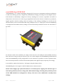
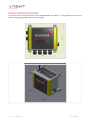
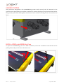
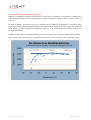
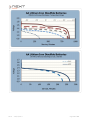
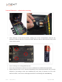
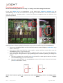
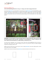
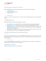
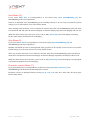
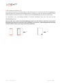
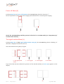
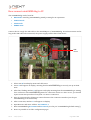
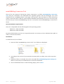
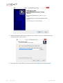
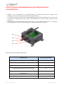
mini OMNIAlog User Manual (from FW 0.12.22) Rev.6 -‐ 28/10/2014 Page 1 of 80 Index PROVISIONS 4 DISPOSAL 5 miniOMNIAlog OVERVIEW miniOMNIAlog default setting 7 INSTALLATION PROCEDURE 8 GROUND SYSTEM HOW TO OPEN miniOMNIAlog CASE 9 miniOMNIAlog POWER SUPPLY 10 Information about Internal Batteries 11 Internal Batteries – Substitution Warnings 13 IDENTIFICATION LABELS 5 DISPLAY AND KEYBOARD FUNCTIONALITY 14 6 9 State menu (1) 16 Battery menu (2) 17 Firmware update menu (3) 18 19 Data copy menu (4) 22 Start menu (5) Stop menu (6) Firmware version menu (7) USB connection menu (8) Set USB flash driver for miniOMNIAlog firmware update Export file (Measure and Measure log) format 23 23 23 24 21 Rev.6 -‐ 28/10/2014 Page 2 of 80 Power off menu (9) 25 Test signal modem menu (A) 25 HOW CONNECT miniOMNIAlog TO PC 26 miniOMNIAlog LOCAL CONNECTION 27 miniOMNIAlog Connection Tool 28 PC-‐miniOMNIAlog connection 32 Try to install wrong version 36 HOW TO DISCONNECT PC FROM miniOMNIAlog 37 Unplug USB without any disconnection procedure 37 USB CONNECTION BY USB ISOLATOR-CABLE 38 2G (GSM/GPRS) MODEM 39 SIM card 39 Caution to be taken with 2G (GSM/GPRS) modem 40 APN configuration 41 WEB PAGES FUNCTIONALITY 42 Type of users 43 Web interface language setup 43 WIRING SCHEMES 44 Local analog sensor 44 Digitalized sensor 45 Wiring 46 RELAY OUTPUT: VOLT-FREE CLOSURE 51 ANOMALIES and ALARM WARNINGS 51 Rev.6 -‐ 28/10/2014 Page 3 of 80 MAINTENANCE 53 TROUBLESHOOTING 54 F.A.Q 59 ASSISTANCE 60 APPENDIX A 61 HOW TO CHANGE THE HARDWARE AND SOFTWARE CHANNELS CONFIGURATION 62 Firmware configuration 63 One input measure type 64 Two input measure type 65 HARDWARE CONFIGURATION 67 Rev.6 -‐ 28/10/2014 Page 4 of 80 Provisions ! Install OMNIAlog in order to avoid the direct sun radiation. ! The product should not be installed in small places and/or without ventilation, with high humidity levels or in the presence of flammable or explosive liquids. Do not open the box with bad weather conditions (rain, snow etc) or if you want to avoid the entry of humid air. miniOMNIAlog was programmed to work at temperatures between -‐30°C and +60°C (batteries from -‐20°C to +60°C) and to be conserved at temperatures between -‐40°C e +85°C (batteries from 0°C to + 40°C). Too extreme temperatures can temporarily shorten batteries lifetime or cause the temporary malfunctioning of miniOMNIAlog. After tightening the cable glands, consider to seal accurately the instrumental cables (with silicone or expanded lather) to guarantee the correct degree of protection of the box. ! ! ! Electrical connections must be done by a qualified technician, respecting the current regulations. ! Before doing works, verify that all connections (also the ones free from potential) are voltage-‐free. Maintenance works have to be done only by qualified technicians. Periodically verify the voltage of the external battery: in case of a value inferior to 11.5Vdc, consider the substitution of the battery and check on the causes. Anyway, battery has to be substituted after 5 years. If, for every reasons, the battery capacity descends under 50%, consider its immediate substitution. Periodically verify the voltage of batteries in batteries-‐holder: in case of a value inferior to 8.4V consider the substitution of the battery and check on the causes Avoid any activity that can put the battery poles in short-‐circuit. The use of non-‐original SISGEO spare parts can cause abnormal functioning and dangers for people and things. Supplied equipments and devices are not suitable to be installed in potentially dangerous areas or in areas where the use of explosion-‐proof components is prescribed. In potentially explosive areas it is necessary to shut down miniOMNIAlog. Possible sparks could cause explosions or fires, causing serious injuries or even death. Generally, areas with a potentially explosive atmospehere are signalled. Consider the periodic substitution of bags of hygroscopic salts. miniOMNIAlog contains fragile parts and components. Do not drop, disassemble, press or deform miniOMNIAlog. Do not use miniOMNIAlog if it is damaged. The lack of respect for this behavior could damage the installed equipment. ! ! ! ! ! ! ! ! ! ! Rev.6 -‐ 28/10/2014 Page 5 of 80 DISPOSAL The disused devices has to be disposed of in accordance with the European directive 2002/96/CE. Recycable materials contained in the device will be recuperated to avoid the environmental degradation. For further information, adress to the local disposal authorithy or to device seller. miniOMNIAlog contains electronic components and batteries that have to be disposed of separately from domestic waste. When this product reach its useful life, it is necessary to bring it to a gathering place for the recycling of electronical components. An uncorrected disposal on the part of the user could be subject to penalties. IDENTIFICATION LABELS Every miniOMNIAlog datalogger, from now on indicated simply as “miniOMNIAlog” or “datalogger” has two type of identification labels.The first label, placed on the upper side of miniOMNIAlog, shows the registration Serial Number of the product. It is important to communicate these data in case of request of information or accessories concerning the product. The second label, placed on the back side of miniOMNIAlog, shows information about the electrical equipment of the product. Respect the requirements written on the label. The lack of respect for these requirements could damage the product or put in danger the operator. Rev.6 -‐ 28/10/2014 Page 6 of 80 miniOMNIAlog OVERVIEW “miniOMNIAlog” is a 4 channel datalogger designed for low power consumption and easy installation; it reads most analog (current, voltage, NTC, Wheathstone bridge), vibrating wire and digital sensors. Each channel is individually configured at factory. Readings are accurate, repeatable and stable in temperature. VW sensors are read using an algorithm based on Fast Fourier Transform; a parameter, logged together with the reading, shows the quality of the readings. Readings are stored into the internal memory and can be downloaded using a USB pen drive or a laptop/PC. If the mini OMNIAlog is equipped with the GPRS module, readings can be automatically transmitted to the user FTP folder or by email. No software needs to be installed: you simply connect the PC to the USB port and establish a dial-‐up PPP connection. Using an internet browser, the user could configure the miniOMNIAlog and download data; the miniOMNIAlog is fully configurable: for each channel it is possible to set the acquisition time, the conversion parameters and the alarm method (SMS, email, digital output, frequency increasing). It is possible to update the firmware / web pages using the USB pen drive. miniOMNIAlog does not support a Dial-‐UP M2M remote communication. NOTE: Power supply type (internal batteries or external power supply), the measure type of each analog channel (current, voltage, NTC, Wheatstone bridge, vibrating wire) and the present of the GPRS module are configured at factory. The user is not authorized to modify these settings. Rev.6 -‐ 28/10/2014 Page 7 of 80 miniOMNIAlog default setting miniOMNIAlog utilizes the following IP address for USB connection with the PC: IP Address: 192.168.125.1 NOTE: this IP address cannot be changed by the user because it is configured at factory. This IP could be utilized only to use the web server on USB communication. After the connection miniOMNIAlog asks for the access credentials. NOTES: ! ! miniOMNIAlog is compatible with the main internet browsers (FireFox, IE9, Safari, Chrome). SISGEO recommends the use of FireFox to manage miniOMNIAlog; First page upload can take some time. Following there are the default credentials: User “Admin” User “User” User: Admin User: User Psw: Admin Psw: User Rev.6 -‐ 28/10/2014 Page 8 of 80 INSTALLATION PROCEDURE You can use the four holes Ø 6mm to fix the miniOMNIAlog according to your application. Screws and anchor plugs (suggested Ø 5mm) are not supplied. Rev.6 -‐ 28/10/2014 Page 9 of 80 GROUND SYSTEM The protections integrated in the miniOMNIAlog system work correctly only if connected to the ground. Use an appropriate green-‐yellow conductor to connect the plug to the ground as shown below. The ground system must be designed, manufactured and certified according to the rules and laws in force. HOW to OPEN miniOMNIAlog Case To open the miniOMNIAlog case use a little screwdriver, insert the screwdriver into the hole in the yellow plastic and press down to unlock the case. 0 Rev.6 -‐ 28/10/2014 Page 10 of 80 miniOMNIAlog POWER SUPPLY miniOMNIAlog is powered by: • 6 AA non-‐rechargeable batteries or • an external power supply (i.e. solar panel). Here below are shown the clamps where the power supply is connected. Respect the polarity. To preserve batteries life, during PC connection the power supply is automatically taken from the PC through USB cable connection. In any case, it is necessary to connect to a power supply. NOTE: the maximum current permitted on the mini USB connector is 500mA. This current limitation must be taken into account when you are powering this device, for example it is not possible to turn on the 2G (GSM/GPRS) modem when the USB cable is connected to the PC SYSTEM POWER REQUIREMENTS Voltage: 9 to 14 V DC (reverse polarity protected), max 12W External rechargeable battery (i.e. from a little solar panel system): 12V DC nominal In case of external power supply, the external power source must be separated from the parts in dangerous voltage with a double insulation and must guarantee an insulation of at least 3000Vrms. An external switch, appropriately labeled, has to be integrated into the plant for power disconnection. The power cable used must have a section of at least 0.5mmq and a rating of 70°C. Internal non-rechargeable batteries (no external power supply): 6 batteries size AA, chemistry Lithium/ Iron disulfide (Life s2), nominal voltage 1.5 V, min 2 A continuous current discharge, min 2 A pulse Rev.6 -‐ 28/10/2014 Page 11 of 80 capability, min 3 Ah capacity Rev.6 -‐ 28/10/2014 Page 12 of 80 Information about Internal Batteries Lithium iron disulfide (LiFeS2) batteries have a much lower sensitivity to temperature compared to other chemical systems. The recommended operating temperature range is -‐40°C to +60°C (-‐40°F to +140°F). As with all battery systems, service life is reduced as the discharge temperature is lowered below room temperature. Batteries generate power through chemical reactions and these typically run much more slowly at lower temperatures. However, even at -‐40°C, LiFeS2 batteries perform well at the rating drain 200mA. LiFeS2 batteries can deliver approximately full rated capacity at -‐40°C if they are discharged at 25mA. Thus, at these rates, batteries give comparable performances over the entire 100°C operating range. Rev.6 -‐ 28/10/2014 Page 13 of 80 Rev.6 -‐ 28/10/2014 Page 14 of 80 Internal Batteries – substitution warning ! Insert batteries in the batteries-‐holder, making sure of the correspondence between the polarities of battery and those of batteries-‐holder. Batteries that are inserted incorrectly could create a short-‐circuit; ! Do not recharge non-‐rechargeable batteries; ! Do not mix used batteries with the new ones or with batteries of different brand/model; ! Expired batteries have to be removed immediately from the batteries-‐holder and correctly disposed of (according to what was established by local rules): if batteries are left in the batteries-‐holder, some losses could happen and these could damage the miniOMNIAlog. Rev.6 -‐ 28/10/2014 Page 15 of 80 DISPLAY AND KEYBOARD FUNCTIONALITY miniOMNIAlog is provided with a 7-‐segment display and 2 input keys (Select/Enter). The display is started by pressing down one of the 2 keys. You can scroll the menu using Select key. If the user doesn’t send any input in a time equal to Timeout Display (configured in “Energy Management” web page), the display will turn off and the miniOMNIAlog will return in Sleep state. 7-‐SEGMENT DISPLAY KEYBOARD SELECT KEY ENTER KEY Rev.6 -‐ 28/10/2014 Page 16 of 80 This is the chart of states on display. Item Menu Display Code Description Test signal modem A Tests and shows the 2G (GSM/GPRS) modem signal from “0” to “3” State 1 It shows miniOMNIAlog state. Battery 2 It shows battery state. Firmware update 3 It allows miniOMNIAlog firmware updating. Copy Data 4 It copies logs on USB drive. Start 5 It starts the miniOMNIAlog. Stop 6 It stops the miniOMNIAlog. Firmware Ver. 7 It shows the firmware version. USB Connection Power Off 8 It enables the miniOMNIAlog to PC connection. 9 it permit to power off miniOMNIAlog properly This chapter summarizes the general philosophy of display messages, as follows; 1. 2. 3. 4. 5. 1 each code is univocal; so, for example, 1 always identifies the miniOMNIAlog STATE menu; letter A is used as a message of successful operation letter E followed by a number means an error in operations; when sleep state is on, the display is off; to awake the system up, you have to press a key. To turn on the system, you have to press the key a second time: now miniOMNIAlog is totally on and displays the first entry of the main menu. 2 3 4 5 6 7 8 E A Rev.6 -‐ 28/10/2014 Page 17 of 80 State Menu (1) If you press Enter key in correspondence to the miniOMNIAlog state menu (1) entry , the miniOMNIAlog will display the current state. MiniOMNIAlog state Display code Description RUN r miniOMNIAlog in run. CONFIG c miniOMNIAlog in configuration STOP S. miniOMNIAlog in stop. RUN mode CONFIG mode STOP mode The user can read the miniOMNIAlog state when he enters the menu. As the user enters the “miniOMNIAlog state”, a 15 sec timeout begins. After that, the miniOMNIAlog will come back to main menu and will start the timeout display. At timeout display expiration, the display will turn off. While the menu shows the display state, Select key causes the display returning back to main menu (and timeout reset display). Rev.6 -‐ 28/10/2014 Page 18 of 80 Battery Menu (2) If you press Enter key in correspondence to the Battery menu entry (2), the miniOMNIAlog will display the batteries charge state. Here follows the battery levels code scheme: Battery level Display Code Description Low Battery under 30% Medium Battery 50% High Battery 100% LOW charge MEDIUM charge HIGH charge The user can read the miniOMNIAlog state when he enters the menu. As soon as the user enters the battery state, a 15 sec timeout starts. After that, the miniOMNIAlog will come back to main menu and will start the timeout display (it can be set up from the internet). At timeout display expiration, the display will turn off. While the menu shows the display state, Select key causes the display returning back to main menu (and timeout reset display). NOTE: if the miniOMNIAlog has an external power supply, battery state will L or not important in case of external power supply L Rev.6 -‐ 28/10/2014 Page 19 of 80 Firmware updating menu (3) NOTE: miniOMNIAlog should be in “Stop” or “Config” state before using this function. If you press Enter key in correspondence to the menu entry Firmware updating (3), the miniOMNIAlog will run the web and firmware updating from USB flash drive. This menu is different from the others, as updating needs a restart and systems management that are different from standard operations. v Flashing d letter is shown on display during files copy. At the end of files copy, the miniOMNIAlog: 1. shows error if USB flash drive was not found and waits for timeout display or Select key to go back to main menu 2. shows error if files copy failed for a time equal to timeout and then resets. After reset, the miniOMNIAlog will go to its normal state 3. resets and starts bootloader for firmware updating if files copy was successful (flashing b letter will appear during firmware reprogramming). After firmware updating, two things can happen: I. firmware updating was successful, letter A is showed for a time equal to timeout and after that miniOMNIAlog goes to the normal state II. firmware updating failed, the miniOMNIAlog restores old versions from web and resets (letter E is showed for 15 sec.) d b. NOTE: after firmware update, to communicate with miniOMNIAlog, you have to unplug and re- plug the power supply. Rev.6 -‐ 28/10/2014 Page 20 of 80 Set USB flash drive for miniOMNIAlog firmware update SISGEO strongly recommends to keep miniOMNIAlog updated to the last firmware version available to ensure the best performances, to solve any bugs or to implement any improvements and to exploit miniOMNIAlog possibilities. NOTE: the code structure (x.yy.zz) of the firmware version is modified according to the improvement/corrections importance carried out between two versions. When the value “x” is modified, it means that the improvement/modification is of high importance because it changes data structure. In this case you need to proceed as explained in chapter “Update with database structure modification”. A. CHECK NEW FIRMWARE AVAILABILITY To check for any firmware update you have two possibilities: ! ! Automatic check (only with miniOMNIAlog connected to internet) –COMING SOON-‐-‐ Manual check on SISGEO website (www.sisgeo.com) Automatic check happens only when miniOMNIAlog is connected to internet through internal 2G (GSM/GPRS) modem. miniOMNIAlog is programmed to check every 7 days for any new firmware version. When a new version is found, the status icon will become red. The user, through miniOMNIAlog web pages, will be informed that on SISGEO website a new version is available. This new version must be downloaded to proceed with the update. New firmware available icon No new firmware available icon It is possible to check anytime for new firmware on SISGEO website. B. NEW FIRMWARE DOWNLOAD For both possibilities, the download must be performed manually on a PC connected to internet: ! ! ! ! ! Connect to SISGEO website and, in the page PRODUCTS, choose “Readout Units and Dataloggers”; Select “miniOMNIAlog datalogger” from the list; In the right higher part select “Download Firmware”: the download of the .zip file will start; Once the download ends, you will have on the PC a file called “FW x.yy.zz” (where “x” is the major release, “yy” is the web pages version and “zz” is the firmware version); It is necessary to extract the .zip file content in the main directory of an USB flash-‐drive (SISGEO supplies, with miniOMNIAlog, a 4GB pen-‐drive already FAT32 formatted and suitable for miniOMNIAlog reading); the USB pen drive can include other files. In case of problems during the firmware download from SISGEO website or temporary unavailability. Rev.6 -‐ 28/10/2014 Page 21 of 80 It is possible to request the new firmware version contacting SISGEO assistance at : [email protected]. Notes and remarks: 1) The USB flash-‐drive used for the firmware update must be FAT32 formatted. Otherwise the pen drive will not be read from miniOMNIAlog and it will be impossible to update the firmware. 2) It is necessary to copy the whole content of the ZIP file (WEB folders, FW and Restore) directly in the main directory of the USB pen-‐drive, do not use sub-‐folders. NOTE: SISGEO suggests to use a USB flash-drive only for this purpose in order to avoid any unexpected data loss. C. FIRMWARE UPDATE According to the value modified in the firmware version (x.yy.zz), it is necessary to proceed in different ways. You have two different options: ! ! Update without database structure modification – “x” value doesn’t change, while values “yy” and/or “zz” change. Update with database structure modification -‐ Value “x” changes. In case of “Update with database structure modification” the old configuration is not compatible with the new version of firmware. Also the log files (Measures, Events and Alarms) must be deleted after firmware update. If these logs are not deleted, there is the possibility to obtain wrong .CSV files after the first download. Rev.6 -‐ 28/10/2014 Page 22 of 80 Data Copy Menu (4) NOTE: miniOMNIAlog should be in “Stop” or “Config” state before using this function. If you press Enter key in correspondence to the menu entry Data Copy (4), the miniOMNIAlog copies all logs on USB Drive. Flashing letter d is displayed during files copy. At the end of the copy, flashing number . (dot) will be shown to indicate to the user to remove USB flash drive and, after that, letter A if copy was successful. If an error occurred, the system will go to error state and an error code will be shown. v WARNING: it is not possible to connect USB hard drives to this port because these devices need too much current to work correctly. In addition, it is not possible to connect to this port any device different from flash drive (i.e. Bluetooth key, internet key, ect.) At copy process completed, a 15 sec timeout starts. After that, the miniOMNIAlog will come back to main menu and will start the timeout display (it can be set up from the web). At timeout display expiration, the display will turn off. While the menu shows the copy state (error code or OK), Select key causes the display back to main menu (and timeout reset display). While the menu shows the copy result, Enter key causes the timeout reset from 15 sec. Rev.6 -‐ 28/10/2014 Page 23 of 80 . -‐ dot d Rev.6 -‐ 28/10/2014 Page 24 of 80 Export File (Measure and Measure Log) Format With miniOMNIAlog you can download data (measures, events log, alarms logs) using: an USB flash drive a PC (through web interface) a FTP or e-mail A. USB flash Drive ! ! ! After the copy using a USB flash drive, a folder with the following format will be automatically created: <miniOMNIAlogname>Log Within the folder there will be the following four “.csv” files: ! ! ! ! ALog_dd_mm_yy.csv: in this file there are all the alarms detected from the miniOMNIAlog; ELog_dd_mm_yy.csv: in this file the events recorded from the miniOMNIAlog are saved; MLog_dd_mm_yy.csv: in this file the measures in log format are saved. There are also other information such as any alarm for the sensors, the measurements unit, the vibrating wire measurements parameters, etc.; MLog_dd_mm_yy.Column.csv: in this file the measures ordered in columns are saved. This kind of display is suited for data management with spreadsheet. In the file name dd is the day, mm is the month and yy is the year. B. PC When you download data directly from the miniOMNIAlog web pages (there is a specific field for each data file) you can choose the destination folder on your PC and the file name if your Internet browser is well configured. C. FTP or e-‐mail If you set the miniOMNIAlog to transmit the .csv reading file (only the one ordered in columns) by e-‐ mail or by FTP, the name of the file is the following: mLog_dd_mm_yy__hh_mm.csv In the file name hh is the hour, mm is the minute. Rev.6 -‐ 28/10/2014 Page 25 of 80 Start Menu (5) If you press Enter key in correspondence to the menu entry Start miniOMNIAlog (5), the miniOMNIAlog will start acquisitions. Letter A is displayed if the miniOMNIAlog is successfully started; if an error has occurred the system will go to error state and an error code will be shown. After starting result is shown, a 15 sec timeout is started. After that, the miniOMNIAlog will come back to main menu and will start the timeout display. At timeout display expiration, the display will turn off. While the menu shows the start state (error code or OK), Select key causes the display returning back to main menu (and timeout reset display). Stop Menu (6) If you press Enter key in correspondence to the menu entry Stop miniOMNIAlog (6), the miniOMNIAlog will stop acquisitions. Number 8 followed by letter A are displayed if the operation is successful; if an error has occurred the system will go to error state and an error code will be shown. After stop result is shown, a 15 sec timeout is started. After that, the miniOMNIAlog will come back to main menu and will start the timeout display. At timeout display expiration, the display will turn off. While the menu shows the stop state (error code or OK), Select key causes the display returning back to main menu (and timeout reset display). Firmware version Menu (7) If you press Enter key in correspondence to the menu entry Firmware Version (7), the miniOMNIAlog will show the installed firmware version. Firmware version is displayed like the string F-X-X-.-X-X-.-X-X only once. After that, the menu goes back to main menu. Rev.6 -‐ 28/10/2014 Page 26 of 80 USB connection Menu (8) If you press Enter key in correspondence to the menu entry Usb connection (8), the miniOMNIAlog will show the letter A and then the flashing number 0 to indicate to the user that PC connection can be started (time for connection is 30 sec., and after that the miniOMNIAlog goes back to main menu). As connection is on, the flashing number 0 becomes permanent. The user can now use the miniOMNIAlog by PC. NOTE: As the user removes the miniOMNIAlog from PC (so he removes remote PC connection), the display goes back to connection state (flashing “0”) for 40 sec., and during this time the user could reconnect. After 40 sec it goes back to main menu. 0 0. Rev.6 -‐ 28/10/2014 Page 27 of 80 Power off Menu (9) Pressing Enter key in Power off (9) menu, the miniOMNIAlog shows the character “.” Now it is possible to remove the power supply (internal batteries or external power supply). v 9 . NOTE: the miniOMNIAlog could be powered off only if it is in STOP mode (see “Stop Menu (6)” section in this manual) Test signal modem Menu (A) Pressing Enter key in Test signal modem menu entry (A), the miniOMNIAlog shows a blinking “A” and after, it displays a number from 0 to 3. This value indicates the quality of signal: 1 – Low signal 2 – Good signal 3 -‐ Excellent 0 –No signal/Bad signal If you select this function without the presence of the internal modem, an error (E7) appears on the display: E3 Rev.6 -‐ 28/10/2014 Page 28 of 80 E7 NOTE: miniOMNIAlog has to be in “STOP” or “CONFIG” mode before using this function. Otherwise miniOMNIAlog shows error E3. Rev.6 -‐ 28/10/2014 Page 29 of 80 How connect miniOMNIAlog to PC The miniOMNIAlog can be found in: ! RUN mode: stand-‐by (miniOMNIAlog timed), waiting for an acquisition. ! CONFIG mode ! STOP mode ! ERROR state Connect the PC trough the USB cable to the miniUSB port of miniOMNIAlog. From this moment and as long as the USB cable is disconnected, the power supply will be taken from the PC. USB device 1. Select item 8 from display menu and click enter. 2. Letter A will appear on display, meaning that the miniOMNIAlog is correctly set up in STOP state. 3. After that, flashing number 0 will appear on display meaning that the miniOMNIAlog is waiting for a connection. The miniOMNIAlog waits for connection for 30 sec. After 30 sec., you should repeat connection procedure from point 1 to start a connection. 4. Start PC connection by clicking on connect button in the connection window (see the par. miniOMNIAlog local connection). 5. After connection, number 0. will appear on display. 6. Open Browser and enter address 192.168.125.1 7. Enter miniOMNIAlog Username and Password. (see the par. “miniOMNIAlog default setting”) 8. Now it is possible to surf the configuration pages Rev.6 -‐ 28/10/2014 Page 30 of 80 miniOMNIAlog LOCAL CONNECTION To establish a connection through Dial-‐up call with a PC follow the next steps: 1. Install the USB driver (FTDI driver); 2. Run miniOMNIAlog Connection Tool to create the virtual 56000 bps modem and to create the dial-‐up connection; 3. miniOMNIAlog setup. To communicate with miniOMNIAlog by USB connection a small driver (FTDI Driver) is needed, to permit to the PC to recognize the miniOMNIAlog. Usually, if your PC is already connected to the internet when you connect miniOMNIAlog, Microsoft Windows is able to download and install this driver automatically. If Microsoft Windows does not install the driver automatically or your PC is not connected to the internet, you can download the driver for free at the following link: http://www.ftdichip.com/Drivers/VCP.htm You have to do this operation only one time for each PC utilized with miniOMNIAlog. After that, every time a new miniOMNIAlog is connected to these PCs, it will be automatically recognized because the driver is already installed on your PC. SISGEO suggests to check periodically the new releases of driver at the previous link. Rev.6 -‐ 28/10/2014 Page 31 of 80 miniOMNIAlog Connection Tool The tool for the creation of the dial-‐up remote connection is in folder miniOMNIAlog Connection Tool, that you could find in the USB flash drive supplied together with the datalogger. You could download it also in SISGEO website, in the page of the product. This tool allows to create the dial-‐up remote connection and to add the virtual modem 56000bps automatically. The tool is necessary only the first time you connect miniOMNIAlog to the PC or every time a new miniOMNIAlog is connected to the PC. System minimum requirements The tool is compatible with the following Microsoft operating systems: - Windows 7 32bit and 64bit Windows 8 32bit and 64bit No particular hardware resources are required. Instead, it is necessary to have administrative rights in order to execute the software. Installation To install the tool, do as follows: 1. Enter in folder “miniOMNIAlog Connect Tool”. Two folders are displayed. 2. According to the version of your Operative System (32 bit or 64bit), enter in the respective folder. 3. Inside the folder, do a double click on the executable file miniOMNIAlogConnectSetup.exe NOTE: it is necessary to be administrator to start the installation 4. The tool installation starts. In the following display, click on Next Rev.6 -‐ 28/10/2014 Page 32 of 80 5. Indicate the path in which extract the files. You could use the one of default. Once you selected the path, click on Next. 6. Select the name of the folder you want to add to the START menu and push NEXT Rev.6 -‐ 28/10/2014 Page 33 of 80 7. In summary page, click on INSTALL 8. Therefore, the installation starts. This lasts only few seconds. Rev.6 -‐ 28/10/2014 Page 34 of 80 9. At the end of the installation, the following confirmation message appears: 10. Click on FINISH Rev.6 -‐ 28/10/2014 Page 35 of 80 PC-‐miniOMNIAlog CONNECTION To create and establish the first connection between PC and miniOMNIAlog do as follows: • • • • Connect miniOMNIAlog to the PC using the supplied USB cable Wait for the end of the installation of the USB drivers NOTE: if the installation doesn’t start automatically, it is possible to trace the drivers on the USB flash drive supplied with miniOMNIAlog. It is also possible to download it from SISGEO website and do a manual installation Start the tool miniOMNIAlog Connect NOTE: the tool has to be started with function “Run as administrator” (right button of the mouse on tool icon), otherwise the configuration doesn’t end well. This procedure is necessary also if you are the administrator of the PC. If you don’t run “As administrator” the following error will appear: Rev.6 -‐ 28/10/2014 Page 36 of 80 • • • • So, the tool opens. Select the COM port assigned to miniOMNIAlog during the installation of the USB driver. NOTE: to know which COM port has been assigned to miniOMNIAlog, look to the COM ports list in Control Panel\Device Manager, maintaining the PC connected to miniOMNIAlog. If the COM port doesn’t appear in the list, it is possible to click on bottom Refresh ports list to update the available ports. After selecting the right COM port, click on Connect The creation of the remote connection starts. Rev.6 -‐ 28/10/2014 Page 37 of 80 • Once the configuration ended, a confirmation message appears. • As describe in the message, select menu 8 on miniOMNIAlog and press ENTER button (of miniOMNIAlog keyboard). When the 0 blinking press OK on the tool. Rev.6 -‐ 28/10/2014 Page 38 of 80 • Clicking on OK, the connection starts. • • • • • When the connection with miniOMNIAlog is established, the following window appears In this window you can find a reminder of defult IP address of miniOMNIAlog It is possible to close the tool clicking on the X of the window Open any internet browser and enter the IP address 192.168.125.1. NOTE: the 192.168.125.1 IP address cant’ be changed by the user. You will be requested the miniOMNIAlog log in and you can browse in its pages. Rev.6 -‐ 28/10/2014 Page 39 of 80 ! Every time that you need to reconnect a miniOMNIAlog or connect a new one, you have to open miniOMNIAlog Connection Tool, select the correct COM port and click on CONNECT. Rev.6 -‐ 28/10/2014 Page 40 of 80 Try to install wrong version miniOMNIAlog Connection Tool has two different version. One for 32bit operative systems and one for 64bit operative systems. miniOMNIAlog Connection Tool 64-‐bit on 32-‐bit operative system If you try to launch a 64-‐bit version tool on 32-‐bit operative system, after the installation, the following error message appears: To solve this problem you have to uninstall the tool (Control Panel / Programs and Features) and re-‐ install the correct version of miniOMNIAlog Connection Tool. miniOMNIAlog Connection Tool 32-‐bit on 64-‐bit operative system After the installation. iIf you try to launch a 32-‐bit version tool on 64-‐bit operative system no message appears and all seams works fine. But when the miniOMNIAlog Connection tool try to create a new connection the following massage appears: The 32-‐bit tool is able to works under 64-‐bit operative system but is not able to create the connection because the driver of dial-‐up connection is different. Also in this case, to solve this problem you have to uninstall the tool (Control Panel / Programs and Features) and re-‐install the correct version of miniOMNIAlog Connection Tool. Rev.6 -‐ 28/10/2014 Page 41 of 80 ! HOW to disconnect PC from miniOMNIAlog To disconnect the PC from miniOMNIAlog follows this steps: ! on miniOMNIAlog web page press Logout button; ! on Microsoft Windows select the Network icon on the application bar; ! Networks menu will open; Disconnect ! Press on Disconnect button to close the Dial-‐Up connection between PC and miniOMNIAlog NOTE: when the USB cable is unplugged the miniOMNIAlog is rebooted. This is necessary to switch from the USB power supply to the miniOMNIAlog power supply (internal batteries or external power supply) Unplug USB cable without any disconnection procedure If you unplug the USB cable without following the correct disconnection procedure the miniOMNIAlog is rebooted. Under “Data Monitor – Events” a “Power Fail” log appears. Rev.6 -‐ 28/10/2014 Page 42 of 80 USB connection by USB Isolator-‐Cable USB port in miniOMNIAlog is not isolated. For the connection between PC and miniOMNIAlog, SISGEO recommends the use of an isolated USB cable. The USB isolator cable effects a potential decoupling of all USB connections. It is the professional tool to avoid and fight ground loops and equalize currents. It is also important to protect the system against overvoltage, that could damage miniOMNIAlog or cause flood readings. USB isolated cable is especially recommended when the PC and miniOMNIAlog are connected to the main electricity network. If you are using this cable, you need to consider that the maximum supplied current is 400mA, compared to a USB port that provides 500mA (maximal 400mA sourced from the 500mA primary input). Therefore, when miniOMNIAlog is powered using an isolated USB cable it should be noted that: ! ! the USB port of the PC must be capable of delivering at least 500mA current; the connected sensor must not draw more than 35mA. If these two conditions are not respected, you may experience some communication and power supply disconnections. Rev.6 -‐ 28/10/2014 Page 43 of 80 2G (GSM/GPRS) Modem SIM card If the miniOMNIAlog has an internal 2G (GSM/GPRS) modem, a SIM with APN for internet connection is needed. The SIM selected must be enabled to internet traffic to send e-‐mails and files on FTP Server (for further details call your ISP “Internet Service Provider”). Watch the following images to insert the SIM correctly: NOTE: remove the power supply before proceeding. ! Insert the SIM card in the SIM-‐slot. NOTE: pay attention to insert the SIM Card in the right side ! Lock the SIM-‐slot. Rev.6 -‐ 28/10/2014 Page 44 of 80 NOTE: the antenna connector is very delicate, pay attention to not damage its cable. CAUTION TO BE TAKEN WITH 2G (GSM/GPRS) MODEM In case miniOMNIAlog sends measures or alarms by e-‐mail or on FTP server, the user has to take into account that the USB serial of communication is shared with the 2G (GSM/GPRS) modem serial of communication. For this reason, if the user launches miniOMNIAlog from webpages, the PC automatically disconnects. If the user connects later, miniOMNIAlog is automatically put in STOP mode. Therefore, it will be possible to surf the pages. Furthermore, it is impossible to visualize the measures in automatic update in page VISUALIZATION/MEASURES. NOTE: SISGEO suggests, during installation, to not enable e-mail or data transmission on FTP server (both measures and alarms). Once the user has verified the accuracy of readings, it is possible to enable e-‐mail or data transmission on FTP server. Rev.6 -‐ 28/10/2014 Page 45 of 80 APN configuration On the miniOMNIAlog web server you can find a page where you have to edit an APN command. This command is necessary to configure the 2G (GSM/GPRS) modem with the correct parameters according to the selected SIM (these parameters depend on your ISP) On the miniOMNIAlog web server: ! ! ! ! ! select the Advanced page from the left menu; select the Connection page; In the Connection page you have to: o write the APN of your Internet Service Provider (ISP) in the APN field (e.g.web.omnitel.it) NOTE: if, in place of APN, there is the field AT command initialization it is necessary to insert the following command: +CGDCONT=1,”IP”,”APN” (e.g. +CGDCONT=1,”IP”,”web.omnitel.it”) o write the telephone number in “Telephone Number” field to establish a GPRS connection. Usually the number is *99***1# (connection using the default CID 1 overrode with the AT+CGDCONT command). o write the Username and Password according to your ISP parameter Press Save Changes to confirm the modifications Reboot miniOMNIAlog to make the changes effective Rev.6 -‐ 28/10/2014 Page 46 of 80 WEB PAGES FUNCTIONALITY NOTE: The uploading speed of pages could be very slow, especially at first access. This occurs because the browser hasn’t memorized the web pages in its cache yet. You have to wait until the pages are completely loaded, without repeatedly refresh the page. Here you can find a brief description of the main miniOMNIAlog web pages. Web pages are the same of OMNIAlog: pages or fields cannot be modified. STATUS: Shows miniOMNIAlog status. In this page is shown the current miniOMNIAlog mode: - Run: miniOMNIAlog is set and started. It will start acquisitions according to selected configuration. - Config: miniOMNIAlog is in configuration mode. No acquisition is in progress. In this mode it is possible to modify configuration parameters (channel configurations, acquisition time, etc..), delete and download logs. Only “Admin” user can modify the “Config” mode - Stop: miniOMNIAlog is stopped. No acquisition is in progress. In this mode it is possible to download logs but it is not possible to change the configuration. NOTE: the humidity value shows N.C. because miniOMNIAlog hasn’t a humidity sensor on board. CONFIGURATION-ACQUISITIONS: in this page it is possible to set acquisitions frequency. CHANNELS CONFIGURATION-LOCALS: in this page it is possible to set local analog channels on miniOMNIAlog. ATTENTION: For sensors wiring it is necessary to refer to the schemes on miniOMNIAlog web pages or to the par. “Connection Schematics” at the end of this manual. CHANNELS CONFIGURATION - DIGITALS: In this page it is possible to set digital channels to allow miniOMNIAlog to read digital instruments. Until now SISGEO digitalized inclinometers and Tiltmeter (RS-‐485 communication interface and MODBUS RTU communication protocol) have been implemented. For further information, refer to the digitized sensors manual. DATA MONITOR - MEASURE: In this page it is possible to display last miniOMNIAlog acquisition cycle. It is also possible to download miniOMNIAlog executed and saved acquisitions. NOTE: the speed of refresh of the web page may not be sufficient to see the readings changes in real time. Rev.6 -‐ 28/10/2014 Page 47 of 80 Type of user Users type in miniOMNIAlog system are: Admin → this user CANNOT change analog channels; it can change for example acquisition frequency or change the polynomial. This user cannot change settings which depend on hardware system; User → this user can only view and download data Web interface language setup To modify the web interface language, connect miniOMNIAlog and access to web interface with the user (Admin or User) that needs to change the language Then: ! Select , from left menu, Advanced and in the submenus User Management; ! In the page it will be displayed select Language; ! Insert the password in the field Old password; ! Press on Save changes. Now the web interface will be converted in the selected language. To convert also the left menu it is necessary to refresh the web page pressing F5 or the specific symbol on the internet browser address bar. NOTE: To avoid the conservation of the old language, it is necessary to completely delete the internet browser cache. Rev.6 -‐ 28/10/2014 Page 48 of 80 WIRING SCHEMES Local analog sensor The Instruments measure type that can be read with miniOMNIAlog are: ! ! ! ! ! ! ! Voltage 4-20mA Current Loop 2 wires 4-20mA Transmitter 3-4 wires Thermistor NTC Vibrating Wire Vibrating Wire with Thermistor Ratiometric (2 channels needed) On the miniOMNIAlog electronic board there are four analog channels. Each channel has four clamps for the instrument signals (A,B,C,D) and one channel for the instruments shield ( ) Channels Terminal Board CH.1 CH.2 CH.3 CH.4 Rev.6 -‐ 28/10/2014 Page 49 of 80 Digitalized sensor miniOMNIAlog can read also the SISGEO digitalized (RS-‐485,MODBUS) instruments (like In-‐Place Inclinometers and Tiltmeters ) On the miniOMNIAlog board there is one clamp for the digitalized instruments connection. Every clamp has 5 terminals: ! ! 3 for communication (RS-485) – “D+”, “D-“ and “GND” -- 2 for the instruments power supply (V OUT) – “V+” and “GND” -- Digitalized Instruments Clamp ATTENTION: The voltage V OUT (V+ and GND) is switched on and off from the software. V OUT is the unregulated power supply input V IN (V+ and V-). It is not possible to power the digitalized instruments when the USB connection is on. RS-‐485 clamp has a resistance of 120Ω; the same resistance should be exposed at the end of 485 bus. Rev.6 -‐ 28/10/2014 Page 50 of 80 Wiring Refer to the following image for the correct wiring of instruments (analog and digitalized) to the clamp. You have to push the little button over the clamp, insert the wire and release the button. Following this scheme for each instruments measure type. Voltage Rev.6 -‐ 28/10/2014 Page 51 of 80 4-‐20mA Current Loop 2 wires 4-‐20mA Transmitter 3-‐4 wires Rev.6 -‐ 28/10/2014 Page 52 of 80 Thermistor NTC Vibrating Wire Rev.6 -‐ 28/10/2014 Page 53 of 80 Vibrating Wire with Thermistor Rev.6 -‐ 28/10/2014 Page 54 of 80 Ratiometric (6 wire) NOTE. for this measure type, two channels (Ch1+Ch2, Ch2+Ch3 or Ch3+Ch4) are necessary to read the instrument. Potentiometer Digitalized Instruments Rev.6 -‐ 28/10/2014 Page 55 of 80 Rev.6 -‐ 28/10/2014 Page 56 of 80 Relay Output: volt-‐free closure On the miniOMNIAlog board there is one clamp for the relay output (for alarm, etc) managed from the software. The relay output is a volt-‐free closure (low voltage 30V, 1A). Relay Output Note: The relay output change for 1 minute. Anomalies and Alarm Warnings Error Codes When the miniOMNIAlog is in error status, it shows the letter “E” and error codes one after the other. Following, there are miniOMNIAlog error codes. Error Code E0 E1 E2 E3 E4 E5 E6 Description General Communication or FTP/MAIL connection Error. It refers to log events on web server USB Drive not found. Error in file copy. miniOMNIAlog is already in run state. It is impossible to start the miniOMNIAlog. miniOMNIAlog is already in configuration state. Iti s impossible to stop the miniOMNIAlog. Rev.6 -‐ 28/10/2014 Page 57 of 80 The system shows general error codes because it has a simple display and so it would be difficult to encode each case. The system will log the event/error and it will be visible and downloadable from the web. Rev.6 -‐ 28/10/2014 Page 58 of 80 Icons and power supply alarm thresholds miniOMNIAlog with external power supply Icon showed: plug Display: L High alarm threshold: 14V Low alarm threshold: 10.5V miniOMNIAlog with internal battery pack Icons showed: cell (battery) Full battery: voltage≥ 9.6V Medium battery: 8.76V < voltage < 9.6V Low battery: Voltage ≤ 8.76V Display: 3 lines: Voltage ≥ 9.6V 2 lines: 8.76V < voltage < 9.6V 1 line: voltage ≤ 8.76V High alarm threshold: not present Low alarm threshold: 8.76V Rev.6 -‐ 28/10/2014 Page 59 of 80 Maintenance Always disconnect miniOMNIAlog from its power source during maintenance. REPAIR OR MODIFY miniOMNIAlog SISGEO doesn’t allow the user to repair or modify miniOMNIAlog. The lack of respect of this instruction could provoke damages that aren’t covered by any warranty. In case of malfunctioning, contact the assistance SISGEO. miniOMNIAlog cleanliness To clean miniOMNIAlog, use a soft cloth without using any cleaning product. CALIBRATION SISGEO suggests a periodic calibration of miniOMNIAlog every 2 years or when necessary. Contact the Technical Assistance SISGEO to receive further information Rev.6 -‐ 28/10/2014 Page 60 of 80 TROUBLESHOOTING miniOMNIAlog: Basic Troubleshooting This paragraph provides basic miniOMNIAlog troubleshooting tips. Are you up-‐to-‐date? 1. Verify that you installed the last version of firmware 2. Verify that you have the last and the correct version of USB driver 3. Verify that you have an adequate power supply (from battery pack or external power supply) on the V IN clamp of miniOMNIAlog; check if the voltage is within the range accepted by miniOMNIAlog and stable. If miniOMNIAlog doesn’t turn on or the display stops responding Follow this step, testing after each: 1. remove power supply on V IN clamp for 10 seconds and try to reconnect. If miniOMNIAlog doesn’t appear under Windows “ Device Manager” as virtual COM port. Follow these steps, testing after each:: 1. restart your computer. 2. remove and reinstall the USB driver and restart your computer 3. remove power supply on V IN clamp for 10 seconds and try to reconnect. It is impossible to upload the configuration Follow this step, testing after each: 1. in webpage STATUS, verify that OMNIAlog is in “Config” 2. make sure that the configuration you are trying to upload has been created with the same major release of the firmware on OMNIAlog NOTE: if what is written above is correct, the configuration file could be altered. In this case, OMNIAlog warns with an error message; the file is no more usable. We suggest to repeat the configuration process. If OMNIAlog blocks during an acquisition Follow this step, testing after each: 1. verify the events log and refer to the manual “miniOMNIAlog & OMNIAlog_Codes Alarms-‐ Events” for the comprehension of the eventual logs; Rev.6 -‐ 28/10/2014 Page 61 of 80 2. verify that OMNIAlog has a correctly power supply. If the power supply is below the minimum threshold or over the maximum threshold of power supply, OMNIAlog blocks every activity in progress; 3. verify the alarm log to identify the problem and refer to the manual “miniOMNIAlog & OMNIAlog_Codes Alarms-‐Events” to understand the eventual logs; 4. verify if in alarm log it is present an “overcurrent” error. In case of overcurrent, OMNIAlog stops the acquisition. 5. verify the available memory. In case of full memory, OMNIAlog stops the acquisition. It is impossible to download data on the USB flash-‐drive Follow this step, testing after each: 1. verify that the USB flash-‐drive is formatted in FAT32; 2. verify with the PC that the USB flash-‐drive is read without any errors. 1. try with a different USB flash-‐drive Rev.6 -‐ 28/10/2014 Page 62 of 80 miniOMNIAlog: Local Communication Troubleshooting This paragraph provides miniOMNIAlog local communication troubleshooting tips. Are you up-‐to-‐date? 1. Verify that you installed the last version of firmware 2. Verify that you have the last and the correct version of USB driver 3. Verify that you have the correct power supply (from battery pack or external power supply) on the V IN clamp of miniOMNIAlog If you are not able to establish the connection with miniOMNIAlog . Follow these steps, testing after each: 1. be sure that on 7 segment display a blinking 0 appears. If an 8 appears, wait for a blinking 0. 2. check if the virtual COM port is showed under Microsoft Windows “Device Manager” (see “If miniOMNIAlog doesn’t appear under Windows “ Device Manager” as virtual COM port” paragraph.). 3. restart your computer. 4. remove and reinstall the USB driver and restart your computer. 5. remove the power supply on V IN clamp for 10 seconds and try to reconnect. 6. Make sure that the username and password for remote connection are correct. 7. using Hyper Terminal check if the baud rate of serial communication is setting to 115200bps. After having established the connection with Hyper Terminal, if you press ENTER the miniOMNIAlog must answer “AT”. The connection through miniOMNIAlog and computer falls down . Follow these steps, testing after each: 1. be sure that your PC is not set on Energy Saving mode 2. if you are using an isolated USB cable keep in mind that these cables usually can provide a limited current. 3. Try to change the USB cable 4. Try with another USB port of your PC Rev.6 -‐ 28/10/2014 Page 63 of 80 miniOMNIAlog: e-‐mail Sending Troubleshooting This paragraph provides miniOMNIAlog e-‐mail sending troubleshooting tips. The e-‐mail transmission involves different devices. In this document, we try to determine which device could cause the problem and then we try to solve it. The “system” is composed as follows: 1. miniOMNIAlog 2. Internet Service Provider (ISP): allows the communication between miniOMNIAlog and the e-‐ mail server 3. E-‐mail Server (ESP): allows to send and to receive e-‐mails NOTE: it may be that the ISP (Telecom, Vodafone, AT&T, Varizon, etc.) doesn’t coincide with the ESP (Gmail, AOL, etc.) Resolution First of all, insure with your IPS that: 1. The SIM card is enabled to the internet 2. The e-‐mail transmission is allowed on the used APN Secondly, insure with your ESP that: 3. there are no momentary breakdowns on ESP server 4. the username and password of your e-‐mail account are valid and accepted 5. the e-‐mail account you want to use is active These points do not depend on SISGEO. SISGEO cannot solve these problems. If you don’t have any problem with the ISP and the ESP, you could proceed looking for causes on miniOMNIAlog. If miniOMNIAlog doesn’t send any e-‐mail although it is configured. Follow these steps, testing after each: 6. verify the events log and refer to manual “miniOMNIAlog & OMNIAlog_Codes Alarms-‐Events” to understand the eventual logs 7. verify that the SIM card is properly inserted in its slot. 8. verify you inserted your SMTP server account correctly (“SMTP Server Configuration” page) 9. verify that SMTP account is a simple authentication. miniOMNIAlog doesn’t support SSL. 10. verify that there is a 2G (GSM/GPRS) coverage on the site were miniOMNIAlog is installed. In some place there is only a 3G and 4G coverage. miniOMNIAlog is not compatible with 3G, 4G and CDMA networks. 11. verify that there is a good 2G (GSM/GPRS) signal on the site were miniOMNIAlog is installed Rev.6 -‐ 28/10/2014 Page 64 of 80 miniOMNIAlog: FTP server Sending data Troubleshooting This paragraph provides FTP server sending data troubleshooting tips. The e-‐mail transmission involves different devices. In this document, we try to determine which device could cause the problem and then we try to solve it. The “System” is composed as follows: 1. miniOMNIAlog 2. Internet Service Provider (ISP): allows the communication between miniOMNIAlog and FTP server 3. server FTP: physical space in which it is possible to memorize files NOTA: the FTP server could be completely transferred to societies that offer an hosting FTP service. It could also be internal. In this secondo case, you have to ask for information to your IT manager. First of all, insure with your IPS that: 1. The SIM card is enabled to the internet traffic through APN 2. The data transmission on FTP server is allowed on the used APN Insure with your system administrator or with the society that supplies the hosting FTP service that: 1. there are no momentary breakdowns on FTP server 2. the username and password of FTP account are valid and accepted 3. that the FTP account and the same FTP server, that the user wants to use, are active These points do not depend on SISGEO. SISGEO cannot solve these problems. If you don’t have problem with the ISP and the FTP server, you could proceed looking for causes on miniOMNIAlog. If miniOMNIAlog doesn’t send any data on FTP server also if configured. Follow these steps, testing after each: 1. verify the events log and refer to manual “miniOMNIAlog & OMNIAlog_Codes Alarms-‐Events” to understand the eventual logs 2. verify that the SIM card is property insert in its slot. 3. verify that you have inserted your FTP server account correctly (“Measure log data transfert” page) 4. verify that the FTP server address is inserted in numeric format (exemple: 62.100.100.1) 5. verify that the FTP server is a basic authentication FTP (for example not MD5, KERBEROS etc.) and that doesn't utilize any secure layer (for example SSH/SSL, FTPS/SFTP etc.). miniOMNIAlog does not support secure layer and encrypted authentication (encrypted username and password). Rev.6 -‐ 28/10/2014 Page 65 of 80 6. verify that there is a 2G (GSM/GPRS) coverage on the site were miniOMNIAlog is installed. In some place there is only a 3G or 4G coverage. miniOMNIAlog is not compatible with 3G, 4G and CDMA networks. 7. verify that there is a good 2G (GSM/GPRS) signal on the site were miniOMNIAlog is installed. Rev.6 -‐ 28/10/2014 Page 66 of 80 miniOMNIAlog: Measure Troubleshooting Are you up to date? 1. Verify that you installed the last version of firmware 2. Verify that you have the correct power supply (from battery pack or external power supply) on the V IN clamp of miniOMNIAlog This paragraph provides measure data troubleshooting tips. One or more vibrating wire instruments are not read. Follow these steps, testing after each: 1. verify the events log and refer to the manual “miniOMNIAlog & OMNIAlog_Codes Alarms-‐ Events” to understand the eventual logs; 2. verify the instrument with a portable datalogger; 3. verify the connection of instruments on miniOMNIAlog inputs; 4. change the parameters “Excitation time” (accepted values from 5 to 100) and “Delay Time” (accepted values from 20 to 100) focusing on this last one; 5. try to contract the parameters “Start Frequency” and “End Frequency” according to the value read with the portable datalogger, 6. consult the reference manual of the instrument One or more analog instruments are not read. Follow these steps, testing after each: 7. verify the events log and refer to the manual “miniOMNIAlog & OMNIAlog_Codes Alarms-‐ Events” to understand the eventual logs; 8. verify the instrument with a portable datalogger; 9. verify the connection of instruments on miniOMNIAlog inputs; 10. verify that the configured parameters are coherent and correct according to the type of connected instrument (power supply, warm-‐up time etc) 11. consult the reference manual of the instrument F.A.Q. (Frequently asked questions) It is possible to find all F.A.Q on SISGEO website at the following link: http://www.sisgeo.com/faq-‐readout-‐units-‐and-‐dataloggers/ Rev.6 -‐ 28/10/2014 Page 67 of 80 ASSISTANCE After-‐sales assistance for calibrations, maintenance and repairs, is performed by Next Industries’ Service Department. The authorization of shipment shall be activated by RMA “Return Manufacturer Authorization". Send back the instrument/equipment with their complete accessories, using suitable packaging, or, even better, the original ones. The shipping costs shall be covered by the sender. Please return to the following address with suitable delivery document: NEXT INDUSTRIES S.r.l. Via F.Serpero, 4/F2 20060 MASATE (MI) On the delivery document is mandatory to indicate the RMA code received. Technical assistance e-mail: assistance@next-industries.com Rev.6 -‐ 28/10/2014 Page 68 of 80 Rev.6 -‐ 28/10/2014 Page 69 of 80 APPENDIX A Rev.6 -‐ 28/10/2014 Page 70 of 80 HOW TO CHANGE THE HARDWARE and SOFTWARE CHANNELS CONFIGURATION ! SISGEO is not responsible for any malfunctioning or damages following the change of the hardware/firmware configuration described in this document. ! To change the firmware you must access miniOMNIAlog through the configurator-‐user ‘Sisgeo’; this user has more privileges than user ‘Admin’ and, therefore you must be really careful to avoid problems. ! The hardware e firmware changes must be coherent; i.e. if the channel CH1 hardware is configured with vibrating wire measure, also the software configuration must be coherent. CH 1 CH 2 CH 3 CH 4 The following are possible configurations: Measure Type Power Supply Available Current loop (2 wires) 24V, 12V, external Transmitter (3-‐4 wires) 24V, 12V, external Voltage (4 wires) 24V, 12V, 5V, external Wheatstone bridge (6 wires, 2 channels used) 5V Thermistor (NTC) -‐-‐ Vibrating wire -‐-‐ Vibrating wire + Thermistor -‐-‐ Rev.6 -‐ 28/10/2014 Page 71 of 80 Firmware configuration In order to configure local analog channels it’s necessary to connect the miniOMNIAlog to a pc (see the miniOMNIAlog Quick Start Manual ). Once established the connection, on your internet browser, insert the IP address of the miniOMNIAlog (192.168.125.1 as default) and login as “Sisgeo” user, with the credentials reported below: USR: Sisgeo PSW: lccee In the main menu, click on Channels Configuration -> Locals: in this page it is possible to set local analog channels on miniOMNIAlog. ! Click on the Enable field, in order to activate the channel. ! Click on the Edit button, in order to configure the channel. Rev.6 -‐ 28/10/2014 Page 72 of 80 One input measure type ! Select 1, by the Input Nr. drop-‐down menu ! Selecting the measure type by the Measure Type drop-‐down menu. Rev.6 -‐ 28/10/2014 Page 73 of 80 Two inputs measure type ! Select 2, by the Input Nr. drop-‐down menu ! Selecting the measure type by the Measure Type drop-‐down menu (only Vibrating wire + Thermistor is available) . ! Configure all the parameters following the properly instrument electric characteristics Rev.6 -‐ 28/10/2014 Page 74 of 80 ! Configure, if necessary, the second input (NTC) also. Rev.6 -‐ 28/10/2014 Page 75 of 80 Hardware configuration After the software configuration of miniOMNIAlog channels it is necessary to change also the hardware configuration according to the measure type of each channels. To change the hardware configuration follows these steps: ! Disconnect the power supply from the miniOMNIAlog. ! According to the Measure Type and Power Supply configurated by web pages for each Channel, insert the jumper on the electronic board (Channel jumpers), following the schemes below: Channels jumpers Channels Terminal Board CH1 CH2 CH3 CH4 Rev.6 -‐ 28/10/2014 Page 76 of 80 Rev.6 -‐ 28/10/2014 Page 77 of 80 Rev.6 -‐ 28/10/2014 Page 78 of 80 Rev.6 -‐ 28/10/2014 Page 79 of 80 Example If you have configured the channel CH1 as Voltage instrument with 12V Power Supply, you should insert jumper at position B1 and D1. If you have configured the channel CH2 as 4-20mA Current Loop (2 wires) with 24V Power Supply, you should insert jumper at position B2, E2 and H2. If you have configured the channel CH3 as Ratiometric (6 wires) with 5V Power Supply, you should insert jumper at position C3 and D3. For this measure type, two channels (CH1+CH2, CH2+Ch3 or CH3+CH4) are necessary. If you have configured the channel CH4 as Vibrating Wire + Thermistor (NTC), you should insert jumper at position A4, D4, F4 and G4. ATTENTION: For sensors wiring it is necessary to refer to the “Wiring scheme” on miniOMNIAlog web pages. Rev.6 -‐ 28/10/2014 Page 80 of 80