1
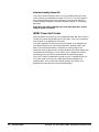
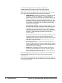
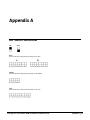
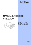
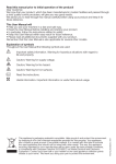
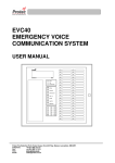
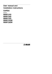
EcoLodgix, LLC.
WDDC System
Installation/User Manual V2.01
®
Software Ingenuity for Intelligent Building Automation.
An ONITY®/UTC Business Partner
EcoLodgix, LLC. SensorStat® WDDC Installation User/Manual V2.01
Contacting
®
Software Ingenuity for Intelligent Building Automation.
An ONITY®/UTC Business Partner
15834 Guild Court, Jupiter, FL 33458
Phone: 561.529-2911 • Fax: 561.743.4338
E-mail: [email protected]
www.ecolodgix.com
This manual was written for use with the WDDC/RCU system, version #1. This manual and the WDDC/RCU
system described in it are copyrighted, with all rights reserved. This manual and the WDDC/RCU system may
not be copied, except as otherwise provided in your system license or as expressly permitted in writing by
EcoLodgix, LLC. a business partner of Onity/UTC Fire & Security.
Export of this technology may be controlled by the United States Government. Diversion contrary to U.S. law
prohibited.
Copyright © 2008 EcoLodgix, LLC. a business partner of Onity/UTC Fire & Security. All rights reserved.
Microsoft, Outlook, Outlook Express, and Windows are either registered trademarks or trademarks of
Microsoft Incorporated in the United States and/or other countries.
Netscape, Netscape Messenger, and Netscape Messenger are registered trademarks of the Netscape
Communications Corporation in the United States and other countries. Netscape's logos and Netscape
product and service names are also trademarks of Netscape Communications Corporation, which may be
registered in other countries.
All other trademarks and service marks are the property of their respective owners.
Use of the WDDC/RCU system and its documentation are governed by the terms set forth in your license.
Such use is at your sole risk. The system and its documentation (including this manual), are provided "AS
IS" and without warranty of any kind and ECOLODGIX, LLC. AND ITS LICENSORS EXPRESSLY DISCLAIM ALL
WARRANTIES, EXPRESS OR IMPLIED, INCLUDING, BUT NOT LIMITED TO THE IMPLIED WARRANTIES
EcoLodgix, LLC. SensorStat® WDDC Installation User/Manual V2.01
OF MERCHANTABILITY AND FITNESS FOR A PARTICULAR PURPOSE AND AGAINST INFRINGEMENT.
ECOLODGIX, LLC DOES NOT WARRANT THAT THE FUNCTIONS CONTAINED IN THE SYSTEM WILL
MEET YOUR REQUIREMENTS, OR THAT THE OPERATION OF THE SYSTEM WILL BE
UNINTERRUPTED OR ERROR-FREE, OR THAT DEFECTS IN THE SYSTEM WILL BE CORRECTED.
FURTHERMORE, ECOLODGIX, LLC DOES NOT WARRANT OR MAKE ANY REPRESENTATIONS
REGARDING THE USE OR THE RESULTS OF THE USE OF THE SYSTEM OR ITS DOCUMENTATION
IN TERMS OF THEIR CORRECTNESS, ACCURACY, RELIABILITY, OR OTHERWISE. NO ORAL OR
WRITTEN INFORMATION OR ADVICE GIVEN BY ECOLODGIX, LLC OR AN ECOLODGIX, LLC
AUTHORIZED REPRESENTATIVE SHALL CREATE A WARRANTY OR IN ANY WAY INCREASE THE
SCOPE OF THIS WARRANTY. SOME JURISDICTIONS DO NOT ALLOW THE EXCLUSION OF IMPLIED
WARRANTIES, SO THE ABOVE EXCLUSION MAY NOT APPLY.
UNDER NO CIRCUMSTANCES INCLUDING NEGLIGENCE, SHALL ECOLODGIX, LLC ITS LICENSORS OR
THEIR DIRECTORS, OFFICERS, EMPLOYEES OR AGENTS BE LIABLE FOR ANY INCIDENTAL, SPECIAL
OR CONSEQUENTIAL DAMAGES (INCLUDING DAMAGES FOR LOSS OF BUSINESS, LOSS OF PROFITS,
BUSINESS INTERRUPTION, LOSS OF BUSINESS INFORMATION AND THE LIKE) ARISING OUT OF THE
USE OR INABILITY TO USE THE SYSTEM OR ITS DOCUMENTATION, EVEN IF ECOLODGIX, LLC OR AN
ECOLODGIX, LLC AUTHORIZED REPRESENTATIVE HAS BEEN ADVISED OF THE POSSIBILITY OF SUCH
DAMAGES. SOME JURISDICTIONS DO NOT ALLOW THE LIMITATION OR EXCLUSION OF LIABILITY FOR
INCIDENTAL OR CONSEQUENTIAL DAMAGES SO THE ABOVE LIMITATION OR EXCLUSION MAY NOT
APPLY.
In no event shall ECOLODGIX, LLC total liability to you for all damages, losses, and causes of action
(whether in contract, tort, including negligence, or otherwise) exceed the amount paid for the system and its
documentation.
April 15, 2008
EcoLodgix, LLC. SensorStat® WDDC Installation User/Manual V2.01
Contents
Contacting EcoLodgix, LLC. .......................................................................................... .........ii
Components
1
Component Configuration
3
Room Control Unit (RCU) Configuration ................................................................................. 4
Setting up the RCU in Basic Mode ............................................................................. 5
Setting up the RCU in Advanced Mode ...................................................................... 9
WDDC Configuration............................................................................................................. . 16
Wireless Door Switch Configuration....................................................................................... 17
Wireless Remote PIR Configuration ....................................................................................... 18
Installing the Devices
20
Installing the Power Control Station (PCS) ............................................................................. 20
Installing the Room Control Unit ............................................................................................ 21
Installing the Local Temperature Sensor ................................................................................. 23
Installing a Wired Door Switch ............................................................................................... 24
Installing the Wireless Door Switch ........................................................................................ 25
Installing the WDDC Wall Unit .............................................................................................. 27
Installing the Remote Motion Sensor (PIR)............................................................................. 29
Using the WDDC
30
Operation of the WDDC .......................................................................................................... 30
Overview................................................................................................................... 30
WDDC Operating Power........................................................................................... 32
WDDC Display ......................................................................................................... 32
WDDC Motion Sensor .............................................................................................. 32
WDDC Diagnostic LED............................................................................................ 32
Soft Bypass................................................................................................................ 33
Humidity Control ...................................................................................................... 33
WDDC Power Up Process......................................................................................... 34
Binding the Devices
35
The Binding Process ............................................................................................................ .... 35
Appendix A
37
DIP Switch Worksheet ........................................................................................................... . 37
EcoLodgix, LLC. SensorStat® WDDC Installation User/Manual V2.01
Contents • v
Appendix B
38
Open Binding Sniffer........................................................................................................... .... 38
The Open Binding Setting ......................................................................................... 38
The Matching BFR Setting........................................................................................ 39
Low Battery – Open Binding Sniffer......................................................................... 39
Contents vi •
EcoLodgix, LLC. SensorStat® WDDC Installation User/Manual V2.01
Components
The WDDC Wireless Energy Management system consists of the following
components:
•
Room Control Unit (RCU) – This component is the brains of the
system. It gets input from all the devices of the system and
makes decisions based on this input.
•
Power Control Station (PCS) - The device that controls the
HVAC system based on the commands given it by the RCU.
•
Wireless DDC (WDDC) – The WDDC wall unit is the user
interface to the system.
•
Wireless Door Switch Transmitter (WDSW) – Monitors the
status of a door.
•
Remote Motion Sensor (PIR) – Motion sensing device used in
applications where additional motion sensing coverage is
needed, such as in a Suite scenario.
•
Remote Temperature Sensor (RTS)– An optional temperature
sensor that is wired to the RCU. When used, it is installed in the
return airway of the air handler.
•
Wired Door Switch (DSW) – The door switch can be wired to
the RCU if desired.
The WDDC Wireless Energy Management system, when used "online" to
innPULSE, also includes the following components:
•
LAN Access Point (LAP) – This component is bridge between
the wireless communications and the wired communications
within the complete innPULSE system. The wireless "side" of the
unit "talks" to the RCU’s. The wired "side" of the unit "talks" to
the innPULSE Server.
•
USB Radio Adapter (URA) – This component houses the
standard radio circuit and plugs directly into the USB port of a
"USB host" level computer.
EcoLodgix, LLC. SensorStat® WDDC Installation User/Manual V2.01
Components • 1
Door/Window Transceiver
Door Switch
Wireless PIR Sensor
HVAC Unit
Room Control Unit
Wireless Thermostat
LAP Floor 1
InnPULSE Server
Typical WDDC/RCU Network
2 • Components
EcoLodgix, LLC. SensorStat® WDDC Installation User/Manual V2.01
Component Configuration
Before installing the components, the wireless devices must be configured
for use.
NOTE: The RCU has two possible modes.
The configuration process for Basic Mode
is very different than that of Advanced
Mode!!!
In both modes, you must first configure the RCU
before any of the other devices in the room. In
Basic Mode, this is done with switches physically
located on the RCU. In Advanced Mode, this is
done with the RF Commissioning Tool. The
Commissioning Tool is a computer program
running on a PC and using the USB Radio
Adapter.
After configuring the RCU, then the WDDC
(Thermostat), the Wireless Door Switch
Transmitter, and the Wireless Remote Motion
Sensor (PIR) are configured. The process to
configure these devices is independent of the
mode of the RCU.
EcoLodgix, LLC. SensorStat® WDDC Installation User/Manual V2.01
Component Configuration • 3
Room Control Unit (RCU) Configuration
Configuring the RCU starts with selecting the mode.
There are two modes of operation for the RCU:
Basic Mode and Advanced Mode.
(Advanced Mode is required for the RCU to communicate online with
innPULSE).
The mode is determined by the jumper on the bottom right side of the RCU.
(Some older RCUs show this jumper as "Jumper In = Offline, Jumper out =
Online). The RCU must be powered off and then on AFTER the jumper is
set or removed and AFTER DIP switches are set for the mode to
change.
With the jumper "IN" the RCU powers up into Basic Mode.
With the jumper "OUT" the RCU powers up into Advanced Mode.
The Jumper that
determines Basic or
Advanced Mode is
located here
In Basic Mode, the RCU is configured entirely by using 16 DIP Switches
located on the side of the unit. (There are two sets of 8 switches labeled ‘A’
and ‘B’).
4 • Component Configuration
EcoLodgix, LLC. SensorStat® WDDC Installation User/Manual V2.01
Switch
Set "A"
Switch
Set "B"
The 16 DIP switches are
located here
In Advanced Mode, the RCU is primarily configured with software running
on a PC (the software is called RF Commissioning Tool, and is required to
setup the RCU in Advanced Mode.); however, some of the DIP switch
settings must be set correctly for Advanced Mode. Modifications to the RCU
parameters after this initial configuration can be done through innPULSE, or
can also be done by re-using the RCU Commissioning Tool software.
The unit must be powered off and powered on before any
changes will take effect.
Appendix A contains a sheet that can be copied or printed and the
desired settings penciled in to be used as an easy setup reference
guide.
Setting up the RCU in Basic Mode
Note: It is possible to
set up the RCU as a
slave device to a Master
RCU
The Room Control Unit (RCU) is the Master device for this
system. All the peripheral devices transmit information to the
RCU. The RCU then determines what to do with the information.
In some scenarios, more than one RCU is needed because a
room or suite is equipped with more that one air handler,
controlled by a single thermostat. In this case, one RCU is
designated as the Master and the others are configured as
Slaves.
EcoLodgix, LLC. SensorStat® WDDC Installation User/Manual V2.01
Component Configuration • 5
(BASIC MODE ONLY - SEE "Setting
up the RCU in Advanced Mode"
below for Advanced Mode
B(asic) M(ode)-A1. Set the DIP switches
In Basic Mode the RCU is configured using 16 DIP Switches located on the
side of the unit. There are two sets of 8 switches labeled ‘A’ and ‘B’. Table
2 details the programming selections.
Switch 1A
Switch 2A
Unoccupied Setback
Temperatures Summer / Winter
ON
ON
74 / 70 F
23 / 21 C
OFF
ON
76 / 68 F
24 / 20 C
ON
OFF
75 / 69 F
24 / 21 C
OFF
OFF
77 / 67 F
25 / 19 C
Switch 3A
Switch 4A
Occupied Limits
Summer / Winter
ON
ON
OFF
ON
70 / 80 F
21 / 27 C
68 / 81 F
20 / 27 C
ON
OFF
66 / 82 F
19 / 28 C
6 • Component Configuration
OFF
OFF
Disable
Switch 5A
Switch 6A
Auto – Maximum Fan Speed
ON
ON
1
OFF
ON
3
ON
OFF
2
OFF
OFF
1
Switch 7A
Auto Fan ON Function
ON
Low Fan ON when satisfied
OFF
Fan OFF when satisfied
Switch 8A
Exterior Door Timeout
EcoLodgix, LLC. SensorStat® WDDC Installation User/Manual V2.01
ON
Short (20 second) timeout
OFF
Normal timeout
Switch 1B
Auto Unsold Setback
ON
Enable
OFF
Disable
Switch 2B
Temperature Sensor Used
ON
Use WDDC temperature sensor
OFF
Use RCU temperature sensor
Switch 3B
HVAC Type
ON
Standard Heat / Cool
OFF
Heat Pump
Switch 4B
Heat Pump Type
ON
O (REV ON = Cool)
OFF
B (REV ON = Heat)
Switch 5B
Wired Door
ON
Enable
OFF
Disable
Switch 6B
Wired Door Type
ON
Interior
OFF
Exterior
Switch 7B
Compressor EQ Delay
ON
Enable (2 minutes)
OFF
Disable
Switch 8B
Master or Slave RCU
ON
Unit is a slave to another
"master" RCU
OFF
RCU configured as a master
Table 1
Notes:
The Auto – Maximum Fan Speed setting only applies when the RCU will
automatically select the fan speed based on the input from the other devices
in the room. If the WDDC is set up for manual fan control, the manual fan
setting will supersede this automatic setting.
EcoLodgix, LLC. SensorStat® WDDC Installation User/Manual V2.01
Component Configuration • 7
When enabled, the Auto Unsold Setback temperatures are 80 and 64F. After
the room has been unoccupied for 15 hours, the room will enter the unsold
mode.
If using the local temperature sensor connected to the RCU, the low fan
should always be on when the temperature setting of the thermostat is
satisfied. (If switch 2B = OFF then switch 7A = ON)
BM-A2 Set the BFR
The BFR (Building, Floor, Room) is the ID which is unique to each room.
When the RCU is in Basic Mode, this ID is configured automatically by the
RCU. When devices are bound to the RCU, they are also assigned this ID.
When devices such as the WDDC transmit information, only the RCU that is
configured with the specific BFR will respond.
To configure the BFR in Basic Mode, press and hold the CFG button on the
RCU for 3 seconds, then release. The Red light will blink and go out, then
turn on solid. To set the BFR in the RCU in Advanced Mode see the section
"Setting BFR and writing saved parameters in each RCU" under "Component
Configuration". During this BFR configuration process, the RCU actually
transmits a message to make sure the BFR is not already in use. If it is in
use, a new BFR is created. Once the unique BFR is created, the RCU is
configured. If the red light does not come on, or continues to blink without
coming on solid, this is an indication that the radio is not communicating.
BM-A3 Configuring Slave RCU’s
(Only used when one WDDC will work with several RCU’s and
controlling up to four HVAC units)
1. Configure master RCU as shown above. i.e. Allow it to pick
own BFR
2. With power off, set dip switches on RCU that will be used as
slave, set with switch 8b to the on position
3. Power up slave RCU, Red LED will be on steady
4. Press OB/CB on master RCU
5. Press CFG on slave RCU, learns master’s BFR and red LED
turns solid
6. Press OB/CB on master to close binding and complete slave
configuration.
*If when powered up the RCU that is to be used as a slave red
LED comes up solid, which means that it has a BFR stored in
memory, it can still be configured as a slave RCU.
1. Press and release OB/CB on slave RCU, green LED comes
up solid and stays on
2. Press and release OB/CB on master RCU; Master green
LED flashes continuously; slave green LED turns off, which
means it has learned the Master RCU BFR and is configured as
a slave
3. Press and release OB/CB button on Master to close binding
and complete process
8 • Component Configuration
EcoLodgix, LLC. SensorStat® WDDC Installation User/Manual V2.01
Setting up the RCU in Advanced Mode
A(dvanced)M(ode)-A1. Remove the "Mode" jumper (see page 4). Set the
DIP switches. Note the very significant difference in switch settings between
Advanced and Basic modes.
A1
OFF
OFF
ON
ON
ON
ON
ON
ON
OFF
OFF
OFF
OFF
-
A2
OFF
ON
OFF
ON
ON
ON
OFF
OFF
ON
ON
OFF
OFF
-
A3
OFF
OFF
ON
ON
ON
OFF
ON
OFF
ON
OFF
ON
OFF
-
A4
OFF
ON
OFF
ON
OFF
ON
A5
OFF
OFF
ON
ON
-
A6 A7 A8
OFF ON
OFF ON
- OFF ON
- OFF
ON
Basic Mode - Jumper IN
Unoccupied
77/67F (25/19C)
Set Back
76/68F (24/20C)
(Summer/
75/69F (24/21C)
Winter)
74/70F (23/21C)
Occupied
Disabled
Limits
68/81F (20/27C)
(Summer/
66/82F (19/28C)
Winter)
70/80F (21/27C)
Device Index 0
Device Index 1
Device Index 2
Device ID
Device Index 3
Selection
Device Index 4
Device Index 5
Device Index 6
Device Index 7
Configure as Room Control Unit
Configure as Repeater
Basic Mode - Jumper IN
Low
Maximum Fan
High
Speed in
Middle
"Auto" Mode
Low
Fan off when temp satisfied
Low fan when temp satisfied
Disabled
Exterior Door
20 seconds
Timeout
B1 B2 B3 B4
Basic Mode - Jumper IN
Auto unsold
OFF Disabled
setback
ON
Enabled
- OFF Remote (RCU wired) Temperature
Sensor
ON
WDDC
- OFF Heat Pump
HVAC Type
ON
Standard
Heat Pump
- OFF
Type "P"
Type
ON
Type "O"
B5 B6 B7 B8
OFF ON
- OFF ON
- OFF ON
- OFF
ON
Advanced Mode - Jumper OUT
Basic Mode - Jumper IN
Disabled
Wired Door
Enabled
Wired Door
Exterior
Type
Interior
Compressor
Disabled
EQ Delay
Enabled
Master or
Master
Slave
Slave
Advanced Mode - Jumper OUT
If A4 is ON, repeat only same BF
not used
If A4 is ON, repeat everything
not used
not used
not used
not used
not used
Advanced Mode - Jumper OUT
not used
not used
Remote (RCU wired) Temperature
Sensor
WDDC
not used
not used
not used
not used
Advanced Mode - Jumper OUT
Disabled
Wired Door
Enabled
Wired Door
Exterior
Type
Interior
not used
not used
not used
not used
Table 2
EcoLodgix, LLC. SensorStat® WDDC Installation User/Manual V2.01
Component Configuration • 9
AM-A2. Connect the USB radio to the laptop or desktop computer. Start the
program. The first screen will ask for the comm. port that the USB Radio is
plugged into: (Note: this can be determined by looking at the comm. ports
under "Device Manager" under Windows "Control Panel"/"System"
AM-A3. Click OK, and then select the correct comm port (the one the USB
radio is plugged into) in the following screen
10 • Component Configuration
EcoLodgix, LLC. SensorStat® WDDC Installation User/Manual V2.01
AM-A4. Next, select the "Commission Device" tab, and under Device
Selection select "RCU"
EcoLodgix, LLC. SensorStat® WDDC Installation User/Manual V2.01
Component Configuration • 11
AM-A4. Enter the desired (B)uilding (F)loor, (R)oom. Note: The "Sniffing" box
at the top of the screen lets you know if any other devices in other rooms
(other teams doing installs) are in open binding mode. If there are none in
open binding mode, then the box will say "Clear for Open Binding", so click
the "Open Binding" button
AM-A5. Power up the RCU, wait 6 seconds after the red "CFG" LED
illuminates a steady red, then press the "CFG" button. The red "CFG" LED
blinks and then returns to steady illuminated on the RCU after it receives the
BFR from the Commissioning Tool software.
The CFG Button is
located here
The CFG LED (it is the
red LED) is located here
12 • Component Configuration
EcoLodgix, LLC. SensorStat® WDDC Installation User/Manual V2.01
AM-A6. Click the "Close Binding" button, then click the "Write Parameters to
Device" button.
AM-A7. Click the "Firmware Version Request" button to determine if the
correct firmware is loaded in the RCU.
EcoLodgix, LLC. SensorStat® WDDC Installation User/Manual V2.01
Component Configuration • 13
Establishing parameters for all advanced mode RCUs for a
given property
Before setting up the first RCU for a given property, the complete set of
parameters, with the exception of the BFR should be selected and saved to
the PC computer memory. This allows for setting up multiple RCUs without
having to re-enter these parameters for each RCU.
A(dvanced M(ode)-B1. After selecting the correct comm port (step AM-A3
above). select the "Modify Memory" tab and select RCU under Device
Selection. Enter the password and click OK.
14 • Component Configuration
EcoLodgix, LLC. SensorStat® WDDC Installation User/Manual V2.01
AM-B2. Set all of the parameters that are common to all rooms in the
property.
This timer determines
the minutes between the
messages that are
spontaneously generated
by the RCUs and WIMs
(otherwise known as
"periodic reponses".
innPULSE measures and
reports this activity
AM-B3. After all parameters are set as needed, then click "Save
Parameters to Computer".
This saves the parameters to the memory in the computer so that when
commissioning many RCUs, the same parameters can be retrieved and
then set into each RCU.
EcoLodgix, LLC. SensorStat® WDDC Installation User/Manual V2.01
Component Configuration • 15
WDDC Configuration
The WDDC thermostat has a number of functions selectable by setting the
DIP switches on the rear of the unit. Table 2 details these selections.
Switch 1
Temperature Display
ON
Display Room Temperature
OFF
Display Set Temperature
Switch 2
Switch 3
Maximum Fan Speed / Function
OFF
OFF
Auto Fan Only (Fan button
disabled)
ON
ON
Maximum Fan Speed 3
ON
OFF
Maximum Fan Speed 2
OFF
ON
Maximum Fan Speed 1
Switch 4
Temperature Sensor
OFF
Do not transmit temperature
changes
ON
Transmit temperature changes
Switch 5
Fan Functions
OFF
Auto and Manual
ON
Manual Only
Table 2
The unit must be powered off and powered on before any
changes will take effect.
Notes:
•
Temperature Display – If using occupied limits, it is recommended
that the Display Set Temperature option be selected.
•
Fan Functions – If the fan function is set to Auto Fan Only, the
maximum fan speed will be determined by the RCU. If Switch 5 is
set to ON, a maximum fan speed must be selected.
If allowing the fan speed to be manually selected, make sure to
choose the proper maximum fan speed based on the air handler you
are controlling.
•
16 • Component Configuration
Temperature Sensor – If the RCU has a local temperature sensor,
set the WDDC to Do not transmit temperature changes – Switch 4 =
OFF.
EcoLodgix, LLC. SensorStat® WDDC Installation User/Manual V2.01
Wireless Door Switch Configuration
The wireless door switch transmitter can be configured to monitor an exterior
door, an interior door, a window, or an adjoining door. Jumpers JP1 – JP4
must be set accordingly. Table 3 shows the jumper settings used to
configure the switch for the type of door and the index of the switch. These
settings allow a single Room Control Unit to monitor up to 4 interior doors, 4
exterior doors, 4 windows, and 4 adjoining doors.
Figure 1
JP1
JP2
Description
Out
Out
Unit #1
In
Out
Unit #2
Out
In
Unit #3
In
In
Unit #4
JP3
JP4
Description
Out
Out
Exterior Door
In
Out
Interior Door
Out
In
Window
In
In
Adjoining Door
Table 3
Example: To configure the unit as Interior Door, Unit #2, install jumpers
across JP2 and JP3. Do not install a jumper on JP1 or JP4.
Notes:
•
Always use the lowest unit number possible. For example, if 2
interior doors will be monitored, configure them as unit number 1
and unit number 2
EcoLodgix, LLC. SensorStat® WDDC Installation User/Manual V2.01
Component Configuration • 17
The unit must be powered off, the Test Button pushed and held
for 10 seconds, then re-powered on before any changes will take
effect. This will read all jumper positions correctly.
Wireless Remote PIR Configuration
Up to 4 room remote motion sensors and 4 other remote motion sensors can
be monitored by a single Room Control Unit. To do so, each motion sensor
must be assigned a number and type to allow the RCU to properly track the
motion status of each unit. These unit numbers and types are assigned
using jumpers JP1, JP2, and JP3. Refer to Table 4 for these jumper
settings.
Figure 2
JP1
JP2
Description
Out
Out
Unit #1
In
Out
Unit #2
Out
In
Unit #3
In
In
Unit #4
JP3
Out
In
Description
Room PIR
Other PIR
Table 4
18 • Component Configuration
EcoLodgix, LLC. SensorStat® WDDC Installation User/Manual V2.01
Example: To configure a remote PIR as unit #2, Room PIR, insert jumper
JP1 only.
Notes:
•
Always use the lowest unit number possible. For example, if 2
PIRs will be monitored, configure them as unit 1 and unit 2.
•
At the time of this writing, the Other PIR option has not yet been
defined. Do not install jumper JP3. JP3 is used only in
Advanced Mode
•
Always remove jumper JP5 for normal use. This will disable the
diagnostic LED.
The unit must be powered off, the Test Button pushed and held
for 10 seconds, then re-powered on before any changes will take
effect. This will read all jumper positions correctly.
Clearing BFRs (device IDs) on Wireless Door
Transceiver and Wireless PIR Sensors
These devices can store up to 4 BFRs and will accept no more after 4 have
been learned. Once 4 BFRs have been learned the units will not allow binding
of any more units.
Note: It is a good practice to clear BFRs every time you install a device to
assure there is none remaining.
To clear the BFR (ID) on the wireless Door Switch transceiver and PIR sensor
devices, follow the following procedure:
1. Remove the Power Jumper
2. Push and hold the test Button, re-install the power jumper and
continue to hold the Test Button unt il you see the light flash RED. At
this time, all BFRs are cleared.
EcoLodgix, LLC. SensorStat® WDDC Installation User/Manual V2.01
Component Configuration • 19
Installing the Devices
Installing the Power Control Station (PCS)
The Power Control Station should be installed within the Air Handling Unit
(AHU). This is the only device that will be wired to any of the HVAC
equipment. Make the applicable connections from the PCS to the AHU as
shown in Figure 3. Use 0.250” female quick connects to connect the wiring
to the PCS.
Figure 3
Notes on wiring diagrams:
20 • Installing the Devices
EcoLodgix, LLC. SensorStat® WDDC Installation User/Manual V2.01
•
The HVAC system is a generic diagram. Refer to the HVAC
system manual for detailed wiring diagrams and specifications.
•
The W/W2 (Heat) connection is for the Heat connection of a
standard HVAC system and the Stage 2 Heat connection for a
Heat Pump System.
•
If the HVAC system is a heat pump, be sure to connect the
Reversing Valve. You will also need to correctly configure the
Energy Products Room Control Unit based on the type of heat pump system
you have (Type B or Type O). On type B heat pumps, the
reversing valve is ON when heating. On type O heat pumps, the
reversing valve is OFF when heating.
Figure 4
Installing the Room Control Unit
The RCU should be installed in close proximity to the PCS. The PCS – RCU
cable is typically 3ft. (0.9m) long. It is connected by plugging in the RJ45
connector to the PCS jack on the RCU.
EcoLodgix, LLC. SensorStat® WDDC Installation User/Manual V2.01
Installing the Devices • 21
Figure 5
The RF Antenna of the RCU must be run so that it is outside of any metal
enclosure. This will reduce any interference caused by the metal enclosure.
Note: The RCU should NOT be mounted inside the electrical box.
Refer to Figure 6 and Figure 7.
The antenna should be positioned vertically for best possible reception
and should be run outside the metal enclosure.
Figure 6
22 • Installing the Devices
EcoLodgix, LLC. SensorStat® WDDC Installation User/Manual V2.01
Figure 7
Installing the Local Temperature Sensor
A local temperature sensor is available to be installed in the return airway.
This sensor is actually wired to the RCU. The connection is made via a RJ11
connector to the TEMP jack on the RCU. It is important that the sensor is
located in a place that best senses the actual temperature of the room, such
as the return airway. If this sensor is installed in the return airway, it is
necessary to configure the RCU to have the LOW FAN on when satisfied.
When using this sensor, the following DIP Switch settings are required:
•
DIP Switch 7A, Low fan ON when satisfied, should be set to ON.
This will allow the sensor to always sense the actual air temperature
of the room.
•
DIP Switch 2B, Temperature sensor used, should be set to OFF.
This will tell the RCU to use the temperature sensor connected to the
RCU instead of the on board temperature sensor of the WDDC wall
unit.
EcoLodgix, LLC. SensorStat® WDDC Installation User/Manual V2.01
Installing the Devices • 23
Figure 8
Installing a Wired Door Switch
In some installations where the Air Handler is close to the door, it may be
simple to run a wire to the door instead of installing the wireless door
transmitter. In this case, a 2 wire connection is needed from the door switch
to the RCU. The wire is connected to the RCU via a RJ11 connector. The
connection is made to pins 2 and 3 of the DOOR/AUX connector of the RCU.
24 • Installing the Devices
EcoLodgix, LLC. SensorStat® WDDC Installation User/Manual V2.01
Figure 9
When using the wired door switch, The following DIP Switch settings are
needed on the RCU:
•
DIP Switch 5B must be set to ON. This will enable the wired
door switch.
•
DIP Switch 6B must be set to ON if the door is an Interior door,
and OFF is the door is an Exterior door.
Installing the Wireless Door Switch
Note: Do not install the
cover plate until after the
binding process.
The door switch consists of a 2 wire close loop door switch and
the wireless door switch transmitter. The transmitter will fit into a
plastic 2 X 4 J-box (or low voltage mounting bracket) or can be
EcoLodgix, LLC. SensorStat® WDDC Installation User/Manual V2.01
Installing the Devices • 25
surface mounted if needed. Do not install in a metal J-box as
this may interfere with the RF signal. The 2 wires from the door
switch are connected to terminal block TB1 on the transmitter
assembly.
A solid plastic faceplate is used to cover the junction box.
Figure 10
Figure 11
26 • Installing the Devices
EcoLodgix, LLC. SensorStat® WDDC Installation User/Manual V2.01
Figure 12
Installing the WDDC Wall Unit
To install the WDDC, simply attach the mounting bracket to the wall where
the unit will be located. The unit then snaps onto the bracket (See Figure
13).
Note: The three pin connector at the bottom of the unit is for
connecting a diagnostic LED which flashes to indicate whether the
motion sensor is operating properly. The diagnostic LED is used for
testing only. Leaving the diagnostic LED connected will decrease the
life of the batteries.
Figure 13
EcoLodgix, LLC. SensorStat® WDDC Installation User/Manual V2.01
Installing the Devices • 27
Because the Wall Unit has a built in motion sensor, be sure to choose a
location that gives the best unobstructed view of the area at a height of about
5 or 6 feet (1.5 – 2 meters) above the floor.
The PIR detection pattern is 150° horizontal and 30° vertical down (see
Figure 14 and Figure 15).
Figure 14
Figure 15
28 • Installing the Devices
EcoLodgix, LLC. SensorStat® WDDC Installation User/Manual V2.01
Mounting Precautions
For proper installation, the following guidelines should be followed:
•
Do not mount the wall unit directly facing a device that changes
temperature rapidly, such as a heat strip, fire place, etc.
•
Do not mount the wall unit in direct sunlight.
•
Do not mount the wall unit directly above a heat producing
device, such as a lamp or TV.
•
Do not mount the wall unit in the direct air flow of an HVAC vent.
•
Do not mount the wall unit in an area where the PIR detection
pattern is obstructed by furniture, walls, or the opening of a door
which hides the wall unit.
Installing the Remote Motion Sensor (PIR)
Note: Do not install the
cover plate until after the
binding process
The remote motion sensor is installed in a standard 2X4 J-Box
(or low voltage mounting bracket) or may be surface mounted.
Be sure to choose a location that gives the best unobstructed
view of the area at a height of about 5 or 6 feet (1.5 – 2 meters)
above the floor.
The PIR detection pattern is 150° horizontal and 30° vertical down (see
Figure 14 and Figure 15).
EcoLodgix, LLC. SensorStat® WDDC Installation User/Manual V2.01
Installing the Devices • 29
Using the WDDC
The WDDC is the “human interface” of the system. Its function is simply to
allow guest control via the buttons (Power, Fan, Warmer and Cooler, F/C) as
well as housing the PIR motion sensor and temperature sensor. When the
status of the buttons change, motion is detected, the temperature changes,
or the humidity changes, the unit will transmit the status changes to the RCU.
Operation of the WDDC
Overview
Figure 16
In order to increase battery life, the unit only “wakes up” once a minute to
check the status, or when a button is pressed. When the unit wakes up and
checks the status, it only transmits this information if there has been a
change since the last check. Again, anytime the buttons are pressed on the
unit, it will wake up. At this point it will transmit any changes five seconds
30 • Using the WDDC
EcoLodgix, LLC. SensorStat® WDDC Installation User/Manual V2.01
after the final button press. This will allow the guest time to finish making the
setting changes.
Changes in temperature or humidity are only transmitted if the change is 1
full degree (or % for humidty) or greater.
Motion status is only transmitted if it is different from the last check.
If no changes in temperature, humidity, settings, motion status, etc. occur for
a 30 minute period of time, the WDDC will transmit a status message to the
RCU. If the RCU does not receive a message from the WDDC in a 35
minute time period, it determines that there is a problem with the WDDC and
will shut the HVAC system off.
Note: Anytime the unit transmits information to the RCU, it transmits
the status of everything. For example, if there is a change of motion
status, the temperature will be sent as well.
The following information is transmitted as part of the message:
•
Room Temperature
•
Humidity (if applicable)
•
Set Temperature
•
Fan Setting
•
Motion Status
•
Unit ON or OFF
•
Battery Status
The WDDC consists of five buttons:
•
Power On/Off
•
Fan – Depending on the way the WDDC is configured, this
button is used to select Auto, Low, Medium, and High fan
speeds.
•
Warmer – This button is used to raise the set temperature of the
room.
•
Cooler – This button is used to lower the set temperature of the
room.
•
F/C – Used to display the temperature in Fahrenheit or Celsius.
This button is also used to set the WDDC system into Soft
Bypass mode. To do so, press and hold the button for 3
seconds until bp is displayed on the screen, indicating that the
Energy Management functions have now been bypassed in the
RCU for a period of 48 hours.
The WDDC has a built in Passive Infrared (PIR) sensor that will sense
human motion in the sensing area while filtering out motion from non human
sources such as draperies.
EcoLodgix, LLC. SensorStat® WDDC Installation User/Manual V2.01
Using the WDDC • 31
WDDC Operating Power
The WDDC is powered by three AA alkaline batteries. These batteries are
located on the back of the unit. To access them, simply remove the WDDC
from the mounting bracket. When the batteries need replacing, a low battery
symbol is displayed on the LCD screen of the WDDC. For best results, use
only high quality alkaline batteries.
WDDC Low Battery Condition
Always remove the
jumper at the bottom of
the WDDC to disable the
diagnostic LED. This will
increase battery life.
When the battery power of the WDDC drops below 3.9V, the low
battery icon is displayed. At 3.3V, the WDDC will shut down
completely. When 35 minutes elapse with the RCU receiving no
transmissions from the WDDC, the HVAC system will be turned
off.
WDDC Display
The WDDC uses a Liquid Crystal Display (LCD). The LCD shows the
following:
•
Temperature – Depending on how the WDDC is configured,
either the room temperature or set temperature will be displayed.
•
Fan function – Auto, Low, Med, or High.
•
F or C – Fahrenheit or Celsius
•
Low Battery Icon – When the batteries need to be replaced, the
Low Battery icon will be displayed.
•
Set Temp – When the displayed temperature is the setting of the
WDDC, or when the warmer or cooler button is pressed, Set
Temp will be displayed on the LCD indicating that the
temperature displayed is the setting, not the actual room
temperature.
The LCD backlighting comes on anytime a button is pressed on the WDDC.
WDDC Motion Sensor
The WDDC Wall Unit has a built in Passive Infrared (PIR) motion sensor.
The PIR detection pattern is 150° horizontal and 30° vertical down (refer to
Figure 14 and Figure 15 on Page 28). The PIR senses differences in the
temperature of a person in the room and the background temperature of the
walls, furniture and fixtures. As a result, occupants are detected as they
pass through the sensor’s zones; and, any motion from inanimate objects
such as movement from the draperies will not be detected.
WDDC Diagnostic LED
Install a jumper on JP2 (the lower middle section of the WDDC circuit board,
accessible from the bottom of the unit) to enable a diagnostic LED to aid in
testing the motion sensor. When the jumper is installed, the LED will flash
red each time motion is sensed. This jumper must be removed for normal
operation. (See Figure 17)
32 • Using the WDDC
EcoLodgix, LLC. SensorStat® WDDC Installation User/Manual V2.01
Figure 17
Note: For normal operation, the diagnostic LED must be disabled
(jumper removed). This LED is for diagnostic use only.
Soft Bypass
At times, it is necessary to bypass the energy management functions of the
system. To do this, press and hol d the F/C button on the WDDC for 3
seconds and you will see bp (bypass) on the screen. The unit sends a
message to the RCU changing the settings so that it functions as a normal
thermostat with no energy management functions for 48 hours.
Humidity Control
The WDDC includes humidity control (optionally turned off in Advanced
Mode) which is designed to utilize the existing room air conditioner to its
maximum potential for the removal of moisture from the air while providing
significant savings in energy when guests are out of their rooms.
Scientists at the University of Florida, Gainesville have defined the
psychometric zone most favorable to the growth of mold and mildew as being
above 72°F and above 60% relative humidity. The psychometric control
algorithm of the WDDC is designed to maintain a room environment that is
outside the mold and mildew zone.
When a room in the Unoccupied or Unsold Mode reaches its respective
Summer Setback Temperature, the WDDC reads the room's relative
humidity and determines its course of action based on this reading
Relative Humidity Below 60%
If the room's relative humidity is less than 60%, the WDDC will function
normally by turning the HVAC ON and OFF as necessary to maintain the
room temperature to within 2°F of the Unoccupied or Unsold Setback
Temperature.
EcoLodgix, LLC. SensorStat® WDDC Installation User/Manual V2.01
Using the WDDC • 33
Relative Humidity Above 60%
If the room's relative humidity is 60% or more, the WDDC will turn ON the
HVAC until the room temperature reaches 72°F (22°C). The HVAC will then
be turned OFF allowing the room temperature to rise until the respective
Cooling Setback Temperature has been reached. Example 77 unoccupied,
80 unsold.
Note: When the relative humidity in the room falls below 60%, normal
setback control is resumed.
WDDC Power Up Process
When the WDDC first powers up, the backlight LEDs will flash twice, then the
unit will do an initial configuration check of the radio. If there is no response
from the radio, nr is displayed on the screen.
If the radio responds, but has not yet been configured, nb is displayed for 2
seconds and then the unit enters normal operation, although it will not be
able to communicate because it is not bound to a Room Control Unit.
During the power up process, the unit also reads the DIP Switch settings and
configures itself accordingly. For this reason, if any changes are made to
these settings, the unit must be powered down and powered up again.
If the On/Off button is held down on power up until Ln is displayed, the unit
is in Learn mode until it receives a valid Open Binding message or is
powered down. Once a valid open binding message is received, bd is
displayed for 2 seconds, then normal operation begins.
34 • Using the WDDC
EcoLodgix, LLC. SensorStat® WDDC Installation User/Manual V2.01
Binding the Devices
In order for the system to work correctly, the devices have to be configured to
work together properly. This is a process we call Binding. Because these
devices communicate via radio waves, the devices in the room must be
bound together to ensure proper operation. Failure to properly bind the
devices could result in the devices from one room actually operating the
equipment in another room. Remember, radio waves do not depend on line
of sight as infrared communications do.
The Binding Process
Note: Only 1 Room Control Unit can be in the Open Binding Process at
a time. Before beginning this process, make sure that no other devices
are in the Binding Process. Failure to do this will cause devices to NOT
be properly bound. BINDING THE INROOM DEVICES TO THE RCU IS
THE SAME FOR BOTH BASIC AND ADVANCED MODES.
To verify that no other RCUs are in the open binding mode, use the
Open Binding Sniffer (see Appendix B) available from Energy Products.
Open Binding
"Open Binding" means putting a device (in this case the RCU) into a state in
which it transmits its BFR so that other devices can "hear" it and "learn" it so
that they can communicate with and only with that RCU in the future. Now
that the RCU is set with the unique BFR, the other devices in the room can
be "bound" to it so that they become a part of that particular RCU's small
network. This process is called the ‘Open Binding’ process.
Note: Only one RCU can be in Open Binding mode at a time. Failure to
follow this rule will result in devices being bound to the wrong RCU.
To verify that no other RCUs are in the open binding mode:
1. Use the Open Binding Sniffer (see Appendix B).
2. If using the Commssioning Tool use the "Sniffing" Warning at
the bottom of the ceach screen
The Open Binding
process will
automatically end after 1
minute.
To Open the binding process, press and release the OB/CB
button on the RCU. The Green LED will blink while the open
binding process is active. The RCU will remain in the Open
Binding mode until the OB/CB button is pressed again or after
EcoLodgix, LLC. SensorStat® WDDC Installation User/Manual V2.01
Binding the Devices • 35
one minute has elapsed. If the one minute time period has
passed and all the devices are not yet bound, simply press the
OB/CB button again and continue to bind the remaining devices.
With the RCU in the Open Binding mode, the room devices must Learn the
BFR. The following describes the Learn process for each device:
•
WDDC Wall Unit – Remove the Jumper JP1 located on the rear
of the unit. This will turn the power off. Press and hold the
power button on the front of the unit and reinstall the jumper JP1.
When the display shows LN release the power button. The unit
will display bd when it has learned the BFR from the RCU. Note,
if the wall unit has never been bound to an RCU, the message
nb will display on initial power up. Continue to hold the power
button until LN is displayed.
•
Door Switch Transmitter – Press and hold the test button until
the Green LED comes ON. Release the button (Refer to Figure
1 on page 17 for the location of this button). When the Green
LED blinks twice and turns OFF, the unit is bound. Remember,
each door switch transmitter can be bound to up to 4 RCUs (v2.0
and later). Simply repeat this procedure to bind the unit to
additional RCUs.
To reset the Door Switch Transmi tter (clearing all BFRs), remove
the power jumper, then press and hold the test button while
installing the power jumper. Continue to hold the button until the
LED lights up Red. At this point, release the button. The unit
may now be bound to the RCU.
•
Remote Motion Sensor – Press and hold the test button until
the Green LED comes ON. Release the button (refer to Figure 2
for the location of this button). When the Green LED blinks twice
and turns OFF, the unit is bound.
•
Slave RCU – To configure an RCU as a slave, you first must
make sure that DIP Switch 8B is set to ON. Press the OB/CB
button. The green LED will come. When the Green LED blinks
twice and turns OFF, the unit is bound.
When finished with the binding, press the OB/CB button on the master RCU
if the green LED is still blinking. Test the devices to ensure that all are
properly bound.
When all devices are properly bound and working, install the cover plates on
the door switch transmitters and remote PIR sensors, and replace the door or
cover on the air handler.
36 • Binding the Devices
EcoLodgix, LLC. SensorStat® WDDC Installation User/Manual V2.01
Appendix A
DIP Switch Worksheet
ON
OFF
RCU:
Pencil in the desired Dip Switch settings for the RCU
A
1
2 3 4 5 6 7 8
B
1 2 3 4 5 6 7 8
WDDC
Pencil in the desired Dip Switch settings for the WDDC
1 2
3 4 5
LAP
Pencil in the desired Dip Switch settings for the LAP
1
2 3 4 5 6 7 8 9 10
EcoLodgix, LLC. SensorStat® WDDC Installation User/Manual V2.01
Appendix A • 37
Appendix B
Open Binding Sniffer
The Open Binding Sniffer is an installation tool to aid in the binding process,
as well as in the testing of the devices. This tool is powered by one 9V
alkaline battery.
Figure 18
The Open Binding Sniffer has two settings: Open Binding, and Matching
BFR.
The Open Binding Setting
The open binding setting is used to detect any open binding that is occurring
in the area. When the unit is turned on and set for Open Binding, the unit is
beep and the Configuration LED will blink if it detects an open binding
message.
38 • Appendix B
EcoLodgix, LLC. SensorStat® WDDC Installation User/Manual V2.01
Use this setting before beginning the binding process to ensure that no one
else is in the binding process at the time. If no open binding is detected, then
it is safe to begin binding of the devices you are installing.
The Matching BFR Setting
The matching BFR setting is used to test the devices in the room after they
are bound to the Room Control Unit (RCU). Do the following steps to
correctly configure the unit for this setting:
•
Set the Switch of the Open Binding Sniffer to Matching BFR.
•
Clear any existing BFR from the Open Binding Sniffer. To do
this, turn the unit off, hold the Learn button down and turn the
unit on. Continue to hold the Learn button until the Configuration
LED turns on RED. Release the Learn button. The unit is now
cleared.
Note: If no BFR is currently configured in the Open Binding
Sniffer, upon power up, the Configuration LED will blink
green twice, then blink red twice. If this is the case,
continue on to the next step.
•
Press the OB/CB button on the Room Control Unit.
•
Press and hold the Learn button on the Open Binding Sniffer for
one second, then release. The Green Configuration LED will
turn on. The Green LED will blink and go off, indicating that the
unit is now bound.
With the Open Binding Sniffer bound to the RCU, any transmissions from any
of the devices with a matching BFR will cause the unit to beep and the Green
LED to blink.
For example, to check to see that the door switch is transmitting correctly,
open the door. The Open Binding Sniffer will beep and the green LED will
blink to indicate that the transmission was sent with the correct BFR.
Low Battery – Open Binding Sniffer
When the battery in the Open Binding Sniffer is low, the Yellow Low Battery
LED will turn ON. When this occurs, replace the battery with one 9V alkaline
battery. The battery compartment is located on the rear of the unit.
For maximum battery life, turn off the unit when not in use.
EcoLodgix, LLC. SensorStat® WDDC Installation User/Manual V2.01
Appendix B • 39