1
GENERAL DESCRIPTION
The GOLDILUX MP series of ultraviolet probes must
be used in conjunction with a GOLDILUX MP series
readout unit GRP-1. The probes measure ultraviolet
2.
radiation in units of µW/cm
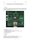
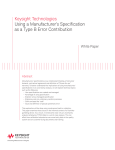
Please consult Fig 2 for choosing the right probe in
the appropriate spectral region.
GOLDILUX
M P SERIES
ULTRAVIOLET PROBES
MODELS
GAP-1
GBP-1
GCP-1
USER MANUAL
GENERAL DESCRIPTION
OPRATING INSTRUCTIONS
MAINTENANCE AND PRECAUTIONS
CALIBRATION
SPECIFICATIONS
WARRANTY INFORMATION
(with the A/D inputs shortened) are taken at
regular intervals by the micro-processor and
subtracted from subsequent probe readings. In
the other ZERO mode, “Rel”, the probe reading
present when the key is pressed is subtracted
from subsequent probe readings. Whenever
"Abs" mode is entered or when the display unit
is switched on, the "Rel" offset value is re-set
to zero. A permanent “Rel” offset can be
introduced by storing a non-zero value in the
probe’s PO (“probe offset”) parameter
(password required). The main use of the PO
feature is to ensure a zero reading on the
display when measuring with the cap on the
detector.
2.
3.
If you would like to "freeze" the displayed
reading momentarily, press the HOLD/RUN
key on the display unit. Press the key again to
see a continuously updated display of the
readings.
If you would like to change the units of
measurement (e.g., from lux to footcandle in
the case of a light probe), press the UNITS key
on the display unit and toggle through the
available options using the UP and DOWN
keys. Once your stored in non-volatile memory
4.
When you plug a probe into a micro-processor
controlled, (MP) series display unit, the
microprocessor first reads all the relevant probe
parameters from a memory circuit in the probe.
These parameters include probe serial number,
probe type, units of measurement, measuring range,
overall calibration factor, range calibration factor for
each probe amplification, probe offset and
calibration date. Then it displays the measurements
from the probe sensor in the selected units on the
display unit's LCD display.
The microprocessor in the display unit also has full
control over the gain switching circuits in the probe
and will autorange the probe (if autoranging mode
is selected) over its full measuring range.
the power per unit area of the UV radiation falling on
the detector. The probes have been specifically
designed and calibrated for use with narrow-ban UV
sources (most UV lamps). In such UV sources most
of the UV radiation is emitted in a narrow
wavelength region around a dominant spectral line.
In the case of doing UV-A and UV-B measurements
of wide-band UV sources (which emit UV radiation
over a wide range of wavelenghts, like for instance
sunlight), this should only be done after having the
probes re-calibrated for that specific type of wideband source. UV-C probes should not be used for
measurements on wide-band sources like sunlight at
all, quite apart from the fact that there is no UV-C
component in sunlight.
The different UV regions are internationally defined
as follows:
UV-A: 315 - 400 nm, UV-B: 280 - 315 nm,
UV-C: 100 - 280 nm.
5.
4.
Check the probe zero with the cap firmly on the
detector. If necessary, zero the probe by
pressing the ZERO key on the keypad of the
display unit.
5.
Remove the protective cap from the probe
detector being used and take readings.
All probes, photometric and radiometric, are
interchangeable. This means they can be plugged
into the display and the correct readout units will be
selected by the microprocessor.
Remove the readout unit and probe from their
case and plug the probe cable into the probe
socket on the display unit.
2.
In case the MANUAL option is chosen when
selecting the integration time, the dose
measurement will be started when the START
/ STOP key is pressed and stopped when it is
pressed again.
6.
In case of a dose measurement, press the
NORMAL / DOSE key on the display unit and
toggle through the available choices of
integration time by using the UP and DOWN
keys. Then press the START / STOP key on
the display unit to start the dose integration
over the selected time interval. The received
dose and the elapsed time will be displayed
simultaneously on the LCD display until the
selected integration period has expired. Then
both the timer and the dose reading will be
frozen in the display until either the START/
STOP key is pressed to commence another
dose measurement or the NORMAL / DOSE
key is pressed (twice) to return to NORMAL
measuring mode.
Switch on the display unit and wait until it has
read the probe parameters.
1.
1.
in the probe and the last selected unit will thus
be used automatically, selection is made,
press the UNITS key again to go back to
measuring mode. The unit selected continues
on the display instrument, after switching off
and on again.
5.
3.
OTHER KEYBOARD FUNCTIONS
1.
The main probe parameters are displayed in a
series of consecutive screens on the LCD
display whenever the PROBE ID key is
pressed.
Mount or place the probe in the position in
which the measurements are to be made. The
probe has two 1/4" mounting holes, which allow
it to be mounted either vertically or horizontally
on e.g. a camera tripod.
OPERATING INSTRUCTIONS
The GOLDILUX series of ultraviolet probes measure
4.
2.
By pressing the AUX key in normal measuring
mode, the following additional instrument
features can be selected by toggling through
the various options with the UP and DOWN
keys:
a)
b)
c)
d)
Display of the ambient temperature in the
display unit.
Display of the display unit battery.
RS232 communications (initiated by
pressing the START button while in this
selection). The RS232 protocol and the
available commands are described in a
later section.
Switch from normal to economy mode
(longer battery life, at the cost of slower
operation and less flexibility). In economy
mode all keyboard selections remain as
set in normal operating mode and the unit
no longer responds to any keyboard or
RS232 input. In order to exit economy
mode, the unit must be switched off.
6.
The display unit's ZERO key toggles the unit
between two "zero" modes. In the "Abs" mode,
A/D (analog to digital converter) zero readings
3.
e)
Display the raw analog-to-digital converter
output (needed for display unit calibration).
MAINTENANCE AND PRECAUTIONS
When not in use, always put the protective cap on
the probe detector and keep the instruments in their
case.
Have a replacement battery ready when the "battery
low" warning appears in the display ("BL"
is
displayed in the lower left part of the LCD display
when the battery voltage reaches a level of about 8
V). The display unit stops measurements altogether
once the battery voltage drops to about 7 V.
If necessary, clean the detector with a soft clean
cloth or tissue moistened with alcohol. Dry and
polish with a dry tissue.
a)
b)
c)
CALIBRATION
Plug the probe into the display unit.
Consult the instruction manual for the GRP-1
unit for details of use.
Expose the probe to a known power per unit
area, emitted by a UV source radiating in the
wavelength region to which the probe is
sensitive and of the type with which the probe
7.
is going to be used. Alternatively, produce a
stable power per unit area with a suitable UV
source of the correct type and measure it with
a calibrated UV meter.
NOTE
:
Calibrations should only be
performed by trained metrologists in
a recognized calibration laboratory.
SPECIFICATIONS
Measurement parameter
Irradiance (power per unit area) or energy density
(dose).
Dynamic range :
Readout
:
Power source
Detector
:
:
1: 2 000 000.
4½ digit LCD display
autoranging over one
decade.
9V type PP3 battery. Battery
life approximately 200 hours
for alkaline battery (without
using an external probe).
UV-enhanced silicon
photodiode with filtering for
either UV-A, UV-B or UV-C.
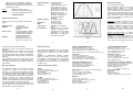
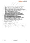
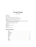
Spectral response : As indicated in Fig. 1
(nominal values).
Accuracy
: Factory setting 5% (UV-A),
10% (UV-B), 15% UV-C.
These figures are applicable
for line sources centred at
365 nm (UV-A), 313 nm (UVB) and 254 nm (UV-C).
Otherwise, as stated on the
calibration certificate by a
recognized calibration
laboratory.
Angular response : As indicated in Fig. 1
(nominal values).
Dimensions
: 110 x 60 x 30 mm.
Mass
: 120 g (with cable).
Accessories
: Protective cap for detector,
manual.
Re-calibration
: Return unit to a recognized
calibration laboratory for recalibration every 6-12 months
(depending on total dose
exposed to) or if calibration is
in doubt for any reason.
Warranty Information
Fig. 1
Exclusions: The above warranty shall not apply to
defects resulting from improper or inadequate
maintenance by the customer, customer-supplied
software or interfacing, unauthorized modifications
or misuse, operation outside the environmental
specifications for the product, improper site
operation and maintenance, an accident or abuse.
Fig. 2
8.
9.
10.
GfG (Pty) Ltd
PO Box 2673, Randburg, 2125
Tel: (011) 955-4862 Fax: (011) 955-4741
Attn: Griselda, Casper van der Westhuizen
E-Mail: [email protected] Http://www.gfg.co.za
H. ROHLOFF (PTY) LTD
770 4th street, Wynberbg, Sandton, 2
PO Box 202, Bergvlei, 2012
Tel: (011) 786-3020 Fax: (011) 887-7199
E-mail: [email protected]
GAMMATEC ENGINEERING (Pty) Ltd
PO Box 264786, Vereeniging, 1939
(016) 454-0260 Fax: (016) 423-3442
Attn: Quinton Bouwer, Nic Coetzer, Jenny
E-Mail: [email protected]
THE DEVENPORT RD LIGHTING COMPANY
73 Buitengracht Str, Tamboerskloof, CapeTown, 8001
Tel: (021) 424-7687 Fax: (021) 424-5211
Cell: 082 4900 350 Attn: Greg Segal
E-Mail: [email protected]
Http://www.devlight.co.za
WILLISTON ELIN (WE)
P O Box 491
Bramley, 2018
Attn: Dennis E Frankel
Tel: (011) 702 2227/8/9 Fax: (011) 702 1507
Warranty limitations
Approved distributor’s address
The manufacturer makes no other warranty, either
expressed or implied, with respect to these
products. The manufacturer specifically disclaims
the implied warranties of merchantability and fitness
for a particular purpose. Some states or provinces
do not allow limitations on the duration of an implied
warranty, therefore the above limitations or
exclusion may not apply to you. However, an implied
warranty of merchantability or fitness is limited to the
one (1) year duration of this written warranty.
This warranty gives you specific legal rights, and
you may also have other rights which may vary from
state to state, or province to province.
CEATEC
PO Box 211, Umzumbe, 4225
Tel: (039) 699-2293 Fax: (039) 699-3129
Attn: Chris Early
E-Mail: [email protected]
Http://www.ceatek.co.za
AMS HADEN Suite 247 Pvt Bag X09, Weltevreden Park,
1714
Attn: Tony Gripping / Steve Bishop
T: (011) 475-2064 F: (011) 475-2062
E-Mail: [email protected]
CT LABS
PO Box 897, Stellenbosch, 7599
Tel: (021) 880-9915 Fax: (021) 880-1863
Attn: Hendrik Burger
E-Mail: [email protected]
Http://www.ctlab.co.za
MAGNITEC
PO Box 27129, Benrose, 2011
Tel: (011) 618-2720/9 Fax: (011) 614-9603
Attn: Paul Nicolai
E-Mail: [email protected]
Http://www.magnitec.co.za
13.
11.
OPAQUE REFERENCE EQUIPMENT
PO Box 25163, Edelweiss, 1577
3 Fulmar Rd, Daggafontein, Springs, 1559
T: (011) 363658 F: (011) 818 5870
E-mail- [email protected]
Exclusive remedies
12.
Obtaining warranty service: To obtain warranty
service, the products must be returned by the
purchaser to an approved distributor. Repair or
replacement of the instrument will be at the
discretion of the technician at the manufacturers.
They have to be notified of the warranty claim and
ENVIROCON INSTRUMENTATION C.C.
PO Box 2686, Northcliff, 2115, JHB
Tel: (011) 476-7323 Fax: (011) 476-5995
Attn: Howard Palmer, Dion van Riet, Brian Stowe
E-Mail: [email protected] Http://www.envirocon.co.za
the defective product returned to them.
Replacement will be at no charge if deemed to be
necessary.
Shipping charges from the customer to an approved
distributor shall be to the account of the customer
and shipping charges from the approved distributor
to the manufacturer shall be paid by the approved
distributor.
The manufacturer shall pay for the return of the
replacement product to the approved distributor,
who shall be responsible for the shipping charges to
the customer.
The remedies provided herein are the customer's
sole and exclusive remedies. In no event shall the
manufacturer be liable for any direct, indirect,
special,
incidental or consequential damages, whether
based on contract, tort, or any other legal theory.
Some states or provinces do not allow the exclusion
or limitations of incidental or consequential
damages, thus the above limitation or exclusion may
not apply to you.
One (1) year limited warranty
The manufacturer warrants the light meters and
probes against defects in materials and
workmanship for a period of one (1) year from the
date of original retail purchase (proof of purchase
required). If an approved distributor receives notice
of such defects during the warranty period, he will
either, at its option, repair or replace products which
prove to be defective and receive a replacement
from the manufacturer.
14.
15.