1
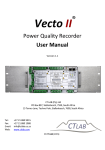
GENERAL DESCRIPTION
The GOLDILUX MP series of illuminance probes must
be used in conjunction with a GOLDILUX MP series,
model
GRP
readout
unit. The probes measure
illuminance in either lux or footcandle (operator selectable).
Ask your authorized GOLDILUX dealer for an up-to-date
product chart if you need to select the appropriate probe
for you requirements.
GOLDILUX
M P SERIES
COSINE CORRECTED
ILLUMINANCE
PROBES
When you plug the probe into a micro-processor controlled
(MP series) display unit, the microprocessor first reads all
the relevant probe parameters from a memory circuit in the
probe. These parameters include probe serial number,
probe type, units of measurement, measuring range,
overall calibration factor, range factor for each
amplification, probe offset and calibration date. Then it
displays the measurements from the probe sensor in the
selected units on the readout unit’s LCD display.
2.
Mount or place the probe in the appropriate
measurement position. The probe has two 1/4"
mounting holes (B in Fig. 1) , which allow it be
mounted either vertically or horizontally on e.g. a
camera tripod.
3.
Switch on the display unit and wait until it has read the
probe parameters.
4.
Check the probe zero with the cap firmly on the
detector (A in Fig. 1). If necessary, zero the meter by
pressing the ZERO key on the keypad of the display
unit.
5.
Remove the protective cap from detector and take
readings.
The microprocessor in the readout unit also has full control
over the gain switching circuits in the probe and will
autorange the probe (if selected) over its full measuring
range.
1.
2.
If you would like to “freeze” the probe reading
momentarily, press the HOLD/RUN key on the keypad
of the display unit. Press the key again to see a
continuously updated display of the readings.
3.
If you would like to change the units of measurement
(e.g. from lux to footcandle), press the UNITS key of
the display unit and toggle through the available
options using the UP and DOWN keys. Once your
selection is made, press the UNITS key again to go
back to measuring mode. The selection unit is stored
in non-volatile memory in the probe and last selected
unit will thus be used automatically, when you switch
on the readout unit with the same probe next time.
OPERATING INSTRUCTIONS
USER MANUAL
1.
Remove the display unit and probe from their case
and plug the probe cable into the socket on the
display unit.
Fig. 1
2.
1.
4.
5.
6.
The main probe parameters are displayed in a
series of consecutive screens on the LCD display
whenever the probe ID key is pressed.
In case of a dose measurement, press the
NORMAL/DOSE key on the display unit and toggle
through the available choices of integration time by
using the UP and DOWN keys. Then press the
START/STOP key on the display unit to start the
dose integration over the selected time interval. The
accumulated dose and the elapsed time will be
displayed simultaneously on the LCD display until
the selected integration period has expired. Then
both the timer and the dose reading will be frozen in
the display until either the START/STOP key is
pressed to commence another dose measurement or
the NORMAL/DOSE key is pressed (twice) to return
to NORMAL measuring mode.
b)
Display of the battery voltage.
c)
RS232 communications (initiated by pressing
the START button while in this selection). The
RS232 protocol and the available commands
are described in a later section.
d)
e)
Switch from normal to
economy mode
(longer battery life, but slower operation and
less flexibility).
In economy mode
all
keyboard selections remain as set in normal
operating mode and the unit no longer
responds to any keyboard or RS232 input.
In order to exit economy mode,
the unit
must be switched off.
Display the raw A/D converter output (needed
for display unit calibration).
MAINTENANCE AND PRECAUTIONS
The MANUAL option allows the user to stat and stop
integration time for the dose measurement. Press
START/STOP key to start and press again to stop.
When not in use, always put the protective cap on the
probe detector and keep the instruments in their case.
By pressing the AUX key in normal measuring
mode, the following additional instrument features
can be selected by toggling through the various
options with the UP and DOWN keys:
Have a replacement battery ready when the “battery low”
warning appears in the display (“BL” is displayed in the
lower left part of the LCD display when the battery voltage
reaches a level of about 7 V.
a)
Display of the ambient temperature in the
display unit.
4.
5.
3.
If necessary,
clean the detector with a soft clean
cloth or tissue moistened with alcohol. Dry and polish
lightly with a dry tissue.
CALIBRATION
a)
Make sure that the “Smart” series display is used with
the appropriate series probe. Ascertain that the
instrument was calibrated according to user manual.
b)
Plug the probe cable into the probe connector on the
display unit and connect the supplied RS232 cable
between the display unit’s RS232 output and the
serial port of PC.
c)
Switch on the display unit.
d)
With the cap firmly on the probe detector, observe the
probe zero and, if necessary, adjust it to zero by
setting the “Rel” zero via the ZERO key on the display
unit.
e)
Run a suitable serial communication programme
like TERMINAL™
for WINDOWS™ ) or the one
supplied with the display unit of the PC (for details nor
the required communications settings see the user
manual of the display unit). Switch the display until to
RS232 mode (one of the available AUX key
selections).
f)
Expose the probe to a known illuminance from a light
source of the type, for which a calibration is desired.
6.
OTHER FUNCTIONS
The display unit’s ZERO key toggles the unit between
two “zero” modes: “Abs” mode - A/D (analog to digital
converter) zero readings are taken at regular intervals
by the micro-processor and subtracted from previous
(consequent) probe readings. In the other ZERO
mode, “Rel”, the current probe reading is subtracted
from subsequent probe readings when this function is
selected. Whenever “Abs” mode is entered or when
the display unit is switched on, the “Rel” offset value is
re-set to zero. A permanent “Rel” offset can be
introduced by storing a non-zero value in the probe’s
PO (“probe offset”) parameter (password required).
The main use of the PO feature is to ensure a zero
reading on the display when measuring with the cap
on the detector.
Alternatively, produce a stable illuminance level with a
suitable light source of the correct type and measure it
with a calibrated meter.
g)
Note the known illuminance in the units of the
meter being calibrated (value =REF) as well as
the reading displayed
by the meter being
calibrated (value = METER).
h)
Using the appropriate command from the display
unit’s RS232 command set, display the probe’s
current probe multiplier PM (value =OLDPM).
i)
Using the same RS232 command set, store the new
calibration factor (value = NEWPM)
NEWPM = OLDPM*REF/METER
in the probe. A knowledge of the display unit’s
password is required for this operation.
j)
A single calibration factor PM entered in this way is
normally sufficient to re-calibrate a probe (the factory
– adjusted ratio of the gains of the different probe
amplifier ranges is unlikely to change significantly). It
is possible to check the consistency of the readings
obtained with different amplifier gains by setting the
probe to different amplifications via the appropriate
commands for the RS232 command set and
comparing the results. If necessary, the individual
range factor can be adjusted via the RS232 command
set to restore full scale consistency. As a factory
7.
default, the range factors R0 to R3 are normalized in
such a way that R3 (the range factor for the sensitive
range) is 0,001. R0 to R2 are then measured relative
to this value.
NOTE :
Calibrations should only be performed
by trained metrologists in a recognized
calibration laboratory.
SPECIFICATIONS
Measuring
parameter
: Illuminance or luminous energy density
(dose)
Measurement
range
: 0-200 000 lux,
0-20 000 footcandle.
Resolution
: 0.01 lux or 0.001 footcandle.
Dynamic range : 1: 20 000 000.
Detector
: Silicon photodiode with photo-metric
filtering.
Angular
response
: As indicated in Fig. 2 (nominal values).
Spectral
response
: As indicated in Fig. 3 (nominal values).
Accuracy
: <3% for commonly used light sources
or as stated on most recent calibration
certificate.
Operating
environment
: 0 to 50EC (-4 to 122EF).
Mass
: 180g.
Accessories
: Protective cap for detector, user manual.
Re-calibration : Return unit to a recognized calibration
laboratory for recalibration every 12 – 18
months (depending on frequency of
usage) or if calibration is in doubt for any
reason.
CIE
parameter:
V(8)match
UV response
IR response
Cosine response
Linearity error
Error of display
Unit
Temperature
coefficient
Fatigue
Modulated
radiation
Polarization
Range change
Crest factor
Lower frequency
limit
Upper frequency
limit
•
**
Warranty limitations
The manufacturer makes no other warranty,
either
expressed or implied, with respect to these products.
The
manufacturer specifically disclaims the implied
warranties of merchantability and fitness for a particular
purpose. Some states or provinces do not allow
limitations on the duration of an
implied warranty,
therefore the above limitations or exclusion may not
apply to you.
However, an implied
warranty of
merchantability or fitness is limited to the one (1) year
duration of this written warranty.
<3%
<0.1%
<0.1%
<1.5%
<0.1%
[f4]
o
["(T2=5 C)]
[f5]
<-0.2%/ C
<0.2%
f7
f8
f11
C
<0.1%
<0.1%
<0.1%
>2
f1
<40 Hz
fu
>50 kHz
9.
Approved distributor’s address:
BEKA (Pty) Ltd
PO Box 120, Olifantsfontein, 1665
Tel: (011)238-0000 Fax: (011) 238-0180
Attn: Murray Cronje, Gustav Kritzinger/Adam
E-Mail: [email protected]
Http://www.beka.co.za
CEATEC
PO Box 211, Umzumbe, 4225
Tel: (039) 699-2293 Fax: (039) 699-3129
Attn: Chris Early
E-Mail: [email protected]
Http://www.ceatek.co.za
CT LABS
PO Box 897, Stellenbosch, 7599
Tel: (021) 880-9915 Fax: (021) 880-1863
Attn: Hendrik Burger
Exclusive remedies
E-Mail: [email protected]
Http://www.ctlab.com
12.
Fig. 2
<0.1%
o
This warranty gives you specification legal rights, and
you may also have other rights which may vary from state
to state, or province.
The remedies provided herein are the customer’s sole
and exclusive remedies. In no event shall the
manufacturer be liable for any direct, indirect, special,
incident or consequential damages, whether based on
contract, tort, or any other legal theory. Some states or
provinces do not allow the exclusion or limitations of
incidental or consequential damages, thus the above
limitation or exclusion may not apply to you.
Exclusions
International Commission on Illumination (CIE)
In accordance with CIE publication 69 (1987),
“Methods of characterizing illuminance meters”.
8.
The manufacturer shall pay for
the return of the
replacement product to the approved distributor, who
shall be responsible for the shipping charges to the
customer.
[f1]
[u]
[r]
[f2]
[f3]
ENVIROCON INSTRUMENTATION C.C.
PO Box 2686, Northcliff, 2115, JHB
Tel: (011) 476-7323 Fax: (011) 476-5995
Attn: Howard Palmer, Dion van Riet, Brian Stowe
E-Mail: [email protected]
Http://www.envirocon.co.za
13.
One (1) year limited warranty
The manufacturer warrants the meters and probes against
defects in materials and workmanship for a period of
one (1) year from the date of original retail purchase
(proof of purchase required). If an approved distributor
receives notice of such defects during the warranty
period, he will either, at its option, repair or replace
products which prove to be detective and receive a
replacement from the manufacturer.
The above warranty shall not apply to detects resulting
from
improper or inadequate maintenance by the
customer, customer - supplied software or interfacing,
unauthorized modifications or misuse, operation outside
the
environmental specifications
for
the product,
improper site operation and maintenance, as well as
through accident or abuse.
Obtaining warranty service
Fig. 3
The products must be returned by the purchaser to an
approved distributor. Such approved distributor shall, at its
discretion, repair or replace products which prove to be
defective. On notifying the manufacturer of the cause of
the warranty claim and returning the defective product to
the manufacturer, the manufacturer will replace the
defective product free of charge.
Shipping charges from the customer to an approved
distributor shall be to the account of the customer and
shipping charges from the approved distributor to the
manufacturer shall be paid by the approved distributor.
10.
11.
GfG (Pty) Ltd
PO Box 2673, Randburg, 2125
Tel: (011) 955-4862 Fax: (011) 955-4741
Attn: Griselda, Casper van der Westhuizen
E-Mail: [email protected]
Http://www.gfg.co.za
MAGNITEC
PO Box 27129, Benrose, 2011
Tel: (011) 618-2720/9 Fax: (011) 614-9603
Attn: Paul Nicolai
E-Mail: [email protected]
Http://www.magnitec.co.za
GAMMATEC ENGINEERING (Pty) Ltd
PO Box 264786, Vereeniging, 1939
(016) 454-0260 Fax: (016) 423-3442
Attn: Quinton Bouwer, Nic Coetzer, Jenny
E-Mail: [email protected]
Opaque Reference Equipment
PO Box 25163, Edelweiss, 1577
3 Fulmar Rd, Daggafontein, Springs, 1559
T: (011) 3631658 F: (011) 818 5870
E-mail- [email protected]
AMS HADEN
Suite 247 Pvt Bag X09, Weltevreden Park, 1714
Attn: Tony Gripping / Steve Bishop
T: (011) 475-2064
F: (011) 475-2062
E-Mail: [email protected]
H. Rohloff (Pty) Ltd
770 4th street, Wynberbg, Sandton, 2
PO Box 202, Bergvlei, 2012
Tel: (011) 786-3020 Fax: (011) 887-7199
E-mail: [email protected]
INDIGENOUS SYSTEMS
PO Box 2662, Halfway House, 1685
Tel: (011) 315-6444 Fax: (011) 315-6432
Attn: Charles Philips, Fanie
E-Mail: [email protected]
14.
THE DEVENPORT RD LIGHTING COMPANY
73 Buitengracht Str, Tamboerskloof, CapeTown, 8001,
Tel: (021) 424-7687 Fax: (021) 424-5211
Cell: 082 4900 350 Attn: Greg Segal
E-Mail: [email protected]
Http://www.devlight.co.za
15.