1
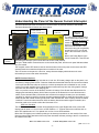
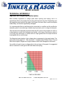
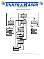
MODEL QUASAR 100 Amp, GPS Current Interrupter User Manual Inside this Manual: Parts List Getting Started o Programming Introduction o Features Physical Connections of the o Settings Programming the Quasar Quasar Watchdog Understanding the Panel of the Maintenance Quasar Current Interrupter Appendix A - Troubleshooting Using the Keypad Appendix A - How do I… Quasar Menu System Appendix B – Menu System Parts List DESCRIPTION QTY DESCRIPTION Interrupter, with battery Connection cables, Large Connection cables, Small Data Transfer cables (USB A/B) 1 1 2 2 9v Watchdog batteries Power cable, AC (120v/240v) User Manual Warranty Card QTY 2 1 1 1 Unpacking The Quasar Current Interrupter comes in a cardboard box with an insert to help protect the instrument during shipment. If possible, retain these items for future use in the event the instrument needs to be shipped. The instrument is housed in a large thermoplastic resin case which includes a storage area for all the cables. Please open the case and remove all cables to ensure that the Model Quasar has shipped with all included parts, as listed above. If any parts are missing, please contact Tinker & Rasor immediately. If the instrument has been damaged in shipping, do not delay in filing a claim with the carrier. Web: www.tinker-rasor.com E-mail: [email protected] QMF-570 105-294 –1– MODEL QUASAR Important Note Regarding Rectifier Spikes Most rectifiers experience a voltage spike when opening and closing, due to a capacitance effect in the system that can be quite large and very fast. Depending upon the magnitude and duration of the spike, the Quasar, and most other current interrupters made today, can become significantly damaged. It is recommended that an oscilloscope be connected to a rectifier and the rectifier be manually cycled to see what type of spike may be present, prior to using an interrupter. This step is suggested for all rectifiers, but is a recommendation if the DC output of the rectifier is 50% or more of the maximum current the interrupter can handle. To better understand this issue, please see Technical Appendix A (attached to this document). Introduction The Model Quasar is an advanced current interrupting instrument and has many new features not found on previous versions of the Quasar. After many years of feedback from customers, Tinker & Rasor has added new functionality to the Quasar and updated and upgraded other essential elements of the 100Amp GPS Current Interrupter. Main Features: 12,000 Watt interrupter (100 amps @ 120 volts, 50 amps @ 240v) Desert Tan case to blend in with surroundings Lockable case (with lid locked closed, or able to open) 120v / 240v auto sensing AC power supply In-case storage for all accessories 6v battery lasts up to 80 hours 4 line LCD allows more information per screen Garmin® GPS technology Small connection cables for systems with less than 5amp circuits Movable GPS antenna Physical Connections of the Quasar Current Interrupter The Model Quasar is an advanced current interrupting instrument and has many features that may not exist on other, similar instruments. Interrupt Connection Cables The Model Quasar offers two (2) methods of connecting the circuit to be interrupted. The main connection points are located on the side of the instrument case, on the Right when facing the panel. The large connection cables push into the large plugs on the side of the case. NOTE: You may notice that the connectors do not fit entirely into the plug. This is normal and not a cause for alarm. The large connection cable set is Orange in color and has large clamps on the opposite end. This is the set of cables to use for most connections and applications. For small current interruption, the large cables and clamps may be inconvenient, and a smaller set of cables have been included for this type of use. The cables come with banana jacks and plug into the same side of the case as the larger cables, just above the plugs. NOTE: The small cables with banana jacks are meant for use on circuits with less than 5 amps of current to be interrupted. Web: www.tinker-rasor.com E-mail: [email protected] QMF-570 105-294 –2– MODEL QUASAR When making the connections to the Quasar there is no need to observe polarity. There is no plus (+) or minus (-) issues when using either set of connection cables. AC Power Cable The Model Quasar is designed to operate on AC power. The internal AC Power Supply will automatically sense and use either 120v or 240v AC when plugged into an AC power source, often found on rectifiers. The AC power cable included with the Model Quasar is designed for use on 120v AC sources. Outside of the United States and for areas where 240v AC is more common, a suitable AC power cord will need to be obtained for use with the Quasar. The AC plug accepts standard PC computer power cables, and this additional power cord should be easy to find in most areas of the world. NOTE: The Quasar will automatically accept either 120v OR 220v AC (single phase) and no switch or adjustment is required. For instances where there is no available AC power supply, the Model Quasar is equipped with an internal 6v battery which will allow the Quasar to operate up to 80 hours in most conditions. Data Transfer Cables The Model Quasar can transfer programming to other Quasar units. The Data Transfer cable is a standard A to B USB cable, frequently used to connect a printer to a computer. The instrument is not USB compliant, and cannot be connected to a printer or a computer. This cable is used simply because it is easy to find throughout the world. NOTE: Do not connect the Quasar to a computer or USB device, such as a flash drive, etc. The Data Transfer is done by connecting the instruments in a “daisy-chain” arrangement. The first Quasar in the line becomes the lead instrument. This is the only instrument that does not have a cable inserted into the “B” USB connector, the square type. Communication is made using the “A” or rectangular USB connector as an Output and the “B” or square connector as an Input. The data transfer operation is done using the keypad, and this is covered later in this manual, in the section titled, Special Features. GPS Antenna The Model Quasar uses a GPS antenna which is magnetically mounted to the main panel. This antenna has a 8’ (2.5 m) lead wire, and may be moved outside of the instrument case to allow the instrument a better view of GPS satellites. The antenna is hardwired into the interior of the case and the antenna cannot be taken off entirely. A small wire cleat is attached to the side of the panel, in the storage area for winding the antenna when it is attached to the main panel of the Quasar. Watchdog System The Model Quasar has a feature called Watchdog. This feature of the Quasar requires two (2) 9v batteries. These batteries are supplied in a plastic bag inside the of the storage area of the case. They are installed in a battery compartment accessed on the side of the inside panel. Using the D ring connector, turn clockwise a ¼ turn and the door will pull open. Inside of the compartment are the two (2) battery connectors. Install each battery in its own battery clip, with the connectors installed. Best fit for the batteries is to have the batteries installed with the connectors pointing down. More information on the Watchdog feature is provided later in the manual, under the Watchdog section. NOTE: Do not open the watchdog battery compartment when the Quasar is operating or connected to an active circuit. Web: www.tinker-rasor.com E-mail: [email protected] QMF-570 105-294 –3– MODEL QUASAR Understanding the Panel of the Quasar Current Interrupter The Model Quasar panel has new features not seen before on previous versions of the Quasar. The Model Quasar panel features are shown below. Watchdog battery access Power On/Off Circuit Closed LED 4 Line, 20 Character LCD display GPS Lock Condition Cable The instrument is now turned on Storage using a push button switch. The switch is located in the upper Left Data Button corner of the16 panel, and must be Transfer Keypad held for 3 seconds to the instrument ON and OFF. The instrument cannot be accidentally turned ON or OFF. An LED will show if the instrument is turned ON. Next to the Power Button is the Circuit Closed LED. This LED will GPS light during the interrupt cycle to show when the circuit is ON (Closed). Antenna The Sync / Data transfer connections are on the inside side panel, and the main panel indicates where (Movable) they are located. The magnetic mount GPS antenna area is near the bottom of the main panel, and is where the GPS antenna should be mounted and kept when not outside of the case. The LCD screen on the panel is a four line, twenty character display which shows much more information per screen than other instruments. NOTE: Previous Versions Previous versions of the Quasar included the 12 volt Aux. DC battery charger jack on the panel, next the Battery Charging Status LEDs. Customer feedback showed that this was an inconvenient location for this port and the short cable to connect to a vehicle powerpoint was not feasible for use, so this option is no longer available. Some Model Quasar instruments may have the older graphic overlays that show the old location of the charging jack. Also on a previous version of the Quasar, the main 6v battery of the Quasar was disconnected for shipping and maintaining battery levels. Newer versions of the Quasar do not use this disconnect switch, as the internal battery connections are sufficient for keeping the battery in a non-shortable condition for shipping purposes. However the panel graphics continue to show this information. If your Model Quasar has a serial number greater than 1000, it DOES NOT have a battery disconnect switch installed. For serial numbers less than 1000, the battery disconnect switch might be installed, and therefore needs to be moved to allow the instrument to run. GPS Lock Condition The GPS lock condition of the Quasar will be displayed in the upper Right hand corner of the LCD display and will show a “0” for no lock to a GPS satellite, a “1” to show minimal, but sufficient lock to three GPS satellites and a “2” for optimal lock on four or more GPS satellites. Below the LCD display is an indicator pointing to the interrupt connections on the outside of the case. Near the bottom Right hand side of the main panel is another indicator pointing to the AC connection on the outside of the case. Web: www.tinker-rasor.com E-mail: [email protected] QMF-570 105-294 –4– MODEL QUASAR Using the Keypad Between these indicators is the sixteen button keypad. The keypad is the main user interface with the instrument and used for all programming and access to all features. Besides the 1 – 9 and 0 keys, there are six other programming keys included with the keypad. They are: OK (Accept), DEL (Cancel), (Forward), (Back), _-> (Up), and . (Decimal). These keys are used to interact with the Quasar during programming and viewing of features. Most are self explanatory, with the possible exception of the “Up” key. This key will allow the user to move up through the menu tree (See Appendix B). This is better described in the section below titled, Quasar Menu System. Programming the Quasar The Quasar is programmed by entering settings via an easy to use menu system. The menu system consists of a Main Menu, Sub Menus, data entry screens and confirmation screens. The Main Menu is the top level screen and gives you the following options: 1. Program 2. Manual Cycling 3. Settings Each of these choices is accessed by pushing the appropriate number button on the keypad; 1 = Program, etc. Program Sub Menu Pressing #1, Program, will bring you to the Program Sub Menu, consisting of the following options: 1. View Programs 2. New Program 3. Upload Programs Pressing #1, View Programs, will show the programs that have been stored in memory. All program data is shown on a single screen. The program data consists of the Program number (#1, #2, #3, etc.) in the upper Left corner of the screen, the Start and Stop Date, the Start and Stop Time and the On and Off Times. Use the FWD (Forward) and BCK (Back) buttons on the keypad to scroll through all the stored programs. NOTE: A program can be deleted in the View Program screens by pressing the Cancel (Delete) button on the keypad. A confirmation screen will come up when the Cancel (Delete) button is pressed to confirm you wish to delete the program. Once the delete program has been confirmed, the program is erased and cannot be retrieved. If there are no programs stored in memory, the screen will show No Programs Stored. Pressing #2, New Program, will access the data entry screens to store a new program. Each step of the programming will ask for confirmation of the data entered. Screen 1: Enter Start Date (mm/dd/yy), Press Ok button. NOTE: mm/dd/yy = two digit month/two digit day/two digit year, example: 01/01/09 for January 1, 2009. Confirm: Press OK or Cancel to re-enter the data. Screen 1: Enter Stop Date (mm/dd/yy). You will see that the Start Date is displayed on the same screen. Confirm: OK or Cancel Web: www.tinker-rasor.com E-mail: [email protected] QMF-570 105-294 –5– MODEL QUASAR NOTE: At any screen during the programming process you can use the Up button on the keypad to go back to the Program Sub Menu. Pressing the Up button again will take you to the Programs sub Menu. Pressing the Up button again will take you to the Main Menu. Screen 2: Enter Start Time (hh:mm:ss). NOTE: Time is entered and displayed as two digit Hour: two digit minute: two digit second. Time is entered and displayed on the 24 hour clock. Two o’clock and ten minutes and zero seconds is entered and displayed as 14:10:00. Confirm: OK or Cancel Screen 2: Enter Stop Time (hh:mm:ss) NOTE: Start and Stop times can be set to happen each day a program runs OR Start Time can happen only on the Start Date and the Stop Time will happen only on the Stop Date. This setting is called Cycling Mode and can be set under the Settings Sub Menu. Start and Stop daily is referred to as Periodic and only on Start and Stop Dates is referred to as Continuous. See Settings Sub Menu for more information. Confirm: OK or Cancel Screen 3: Enter ON Time. This screen will show a blinking cursor and the time may be entered easily with up to three digits before the decimal place and up to three digits after the decimal. For example, an ON time of three seconds can be entered as 3 followed by pressing the OK button. An ON Time of half a second would be entered as 0.5, followed by pressing the OK button. Confirm: OK or Cancel Screen 3: Enter OFF Time. NOTE: ON and OFF are used throughout the Quasar and it is important to understand their meanings. ON refers to the time the Quasar has the circuit Closed, meaning the current is flowing through the interrupter. OFF refers to the time the Quasar has the circuit Open, meaning the current is not flowing through the interrupter. ON = Closed = Protection OFF = Open = No Protection Confirm: OK or Cancel After pressing the Confirm: OK button, the screen will show confirmation that the program was added and stored to memory. Pressing the OK button again will bring you back to the Programs Sub Menu. After adding a program to memory you will notice that most Sub Menu screens will now show the time until the start of the program at the bottom of the display. When there are more than one programs in memory, the program with the nearest Start Date and Start Time will be displayed. Depending on how far in the future the next program to run is, the time may be displayed with a three digit hour in the format hhh:mm:ss. Upload Programs The Model Quasar can sync with other Quasar interrupters via USB cable. The Quasar can be used to sync the clock of non-GPS versions of the Quasar and also to transfer the program data of one Quasar to as many other Quasars as needed. This feature not only saves a lot of time that would otherwise be spent programming, but also removes the possibility of an error in programming on one or more of a group of Quasars that are meant to operate together. The USB cable (supplied) has an “A” and “B” connector at either end. The “A” connector (rectangular) is connected to the Output port of the Quasar and the “B” connector (square) is connected to the Input port of the Quasar. The Quasar that does not have anything plugged into its Input, or “B” port is the Controlling unit in the transfer. The ports are located on the inside side panel, in the storage area of the case. On the Controlling Quasar, Choose #3 in the Programs Sub Menu, Upload Programs. The next screen will ask that you check all connections and press the OK button to start the transfer. Press OK or Web: www.tinker-rasor.com E-mail: [email protected] QMF-570 105-294 –6– MODEL QUASAR Cancel. Cancel will take you back to the Programs Sub Menu. OK will start the upload (transfer) of the programs. All ten programs will transfer in a few seconds. While the transfer is taking place the screen will show “Sync in progress. . .”. The screen will automatically change to show “Done” when the upload is complete. Press OK to return to the Program Sub Menu. NOTE: When using the Upload Programs feature, it is important to note that the memory of all Quasars, with the exception of the Controlling unit, will be erased and overwritten. Manual Cycle Sub Menu The Manual Cycle Sub Menu offers two choices: 1. Start Manual Cycle 2. Get In Sync Start Manual Cycle Start Manual Cycle takes you to a screen where you input the ON and OFF Times. The ON and OFF Times from the last Manual Cycle are kept. Pressing OK starts the interruption cycle with the stored ON and OFF Times, Cancel returns to the Manual Cycle Sub Menu. Pressing the “1” button on the keypad allows you to enter new ON and OFF Time settings. Get In Sync The Get In Sync feature is meant to be used to add a Quasar to a group of Quasars already interrupting. For example, during a close interval pipe to soil potential survey (CIPS), five Quasars are being used to interrupt rectifiers in the field. These five Quasars have been in operation since Monday and it is now Wednesday afternoon and an additional Quasar needs to be added to the group. Use the Get In Sync feature to add additional Quasars to those already in operation. To use Get In Sync, the Quasar units to be added must have identical settings to those already in operation. The Quasar will use the program information of when the Start Date and Start Time happened and what the ON and OFF settings are to determine a new, synchronous Start Time will be. When this time occurs, the Quasar will automatically start interrupting, in sync with the other units. Choose Get In Sync, #2 on the Manual Cycle Sub Menu. Get In Sync Sub Menu Choose #1, “Choose Program from the list”. This will allow you to view the programs in memory to find a program that should have started in the past or will start in the future to use the Get In Sync feature with. Choose #2, “Enter New Program” if the Quasar was not previously programmed as those already in operation had been. This will take you though a set of data entry screens similar to the Programming setup previously discussed in this manual. The main difference between these screens and the New Program screens is that now you can use a Start Date and Start Time that have already occurred. In the New Program screens you can only use Start/Stop Date/Times that will occur in the future. When programming the Get In Sync feature, the Stop Date and Stop Time must still occur in the future. After confirming the ON and OFF times a confirmation screen will appear asking to Start Sync?. OK will begin the countdown to sync, Cancel will take you back to the Get In sync Sub Menu. Once the Quasar begins interrupting, the screen will change to the Interrupting display, as with any active interrupting program. Settings Sub Menu The Settings Sub Menu, #2 from the Main Menu, offers the following options: 1. Change Settings 2. Reset Settings Web: www.tinker-rasor.com E-mail: [email protected] QMF-570 105-294 –7– MODEL QUASAR Change Settings Choosing #1, Change Settings, will take you to the Settings Sub Menu, #4 from the Main Menu, offers the following options: 1. Time / Position 2. Cycling Settings 3. Power Settings Choosing #1 from the Settings Sub Menu brings up the GPS Time and Date. This data has been corrected from Universal Time – UTC (formerly known as Greenwich Mean Time – GMT) to display as your local time based upon your GPS position. If the time displayed is not correct, it can be adjusted in the following steps. Pressing the OK button brings up the Time / Position Sub Menu. Time / Position Sub Menu The Time / Position Sub Menu has three options: 1. Time Zone 2. Set DST 3. View GPS Data Time Zone The Quasar uses the GPS location to automatically adjust the time to a local time zone. However, as most time zones are set as political boundaries and not by exact Latitudinal and Longitudinal lines, the automatic adjustment may be incorrect. The Quasar allows the user to manually set the time zone so the correct local time is displayed. Pressing #1 from the Time / Position Sub Menu brings up a screen that shows: 1. AUTOMATIC 2. manual The current setting of the Quasar is shown in all CAPITOL letters. The alternative choice is show in all lowercase letters. To change from one setting to the other, press the appropriate button, one (1) or two (2). The text will change to all CAPITOL letters showing your choice was made correctly. If MANUAL is selected, pressing OK brings a screen that has a list of time zones. A major city is listed for each of the world’s time zones. Use the arrow buttons on the keypad to select the city which is in the time zone you wish to use. When the correct time zone is highlighted, press the OK button. The change will be confirmed. After pressing OK again, the display will show the new time and date. If AUTOMATIC is selected, pressing OK changes the display to show the time and date. Press OK to return to the Time / Position Sub Menu. Set DST The Quasar does not automatically adjust for Daylight Savings Time (DST). If your time zone uses Daylight Savings Time you can set the Quasar to observe this by pressing #2 from the time / Position Sub menu. The display screen will show: Daylight Savings Time 1. on 2. OFF Again, all CAPITOL letters indicates which setting is in effect. Press the appropriate number button to make a change. Press Cancel to not make a change and return to the Time / Position Sub Menu. Press the button associated with the lowercase letters text and press OK to change the settings. The screen Web: www.tinker-rasor.com E-mail: [email protected] QMF-570 105-294 –8– MODEL QUASAR will change to show the new time and Date. Pressing OK again will return you to the Time / Position Sub Menu. NOTE: Daylight Savings Time is observed in the United States during the summer months. The local time in some US time zones is set forward by one hour. This event may be in use in other parts of the world and referred to in a different manner. The Quasar will not automatically adjust to DST, and so this setting will need to be changed again when Standard time resumes. View GPS Data Pressing #3 in the Time / Position Sub Menu will bring up the actual GPS Time and Date information. This information is displayed in UTC. The Latitude and Longitude of the Quasar unit is also displayed here. Press OK to display the current local time and date. Press OK again to return to the Time / Position Sub Menu. To return to the Settings Sub Menu, use the Up button on the keypad. Cycling Settings Sub Menu The Cycling Settings Sub Menu offers three settings which can be changed by the user. These settings effect the way the Quasar operates during an interruption cycle. The three options are: 1. Set First Cycle 2. Set Cycling Mode 3. Standby Settings Set First Cycle The First Cycle determines whether the Quasar will begin in the ON or OFF position when interrupting starts. NOTE: The Quasar is able to operate in sync with GPS current interrupters made by manufacturers other than Tinker & Rasor, the Quasar is able to adjust whether it begins operation in the ON or OFF position. Refer to the user manual of your non Quasar units to see which cycle mode they use. To make a change to the Quasar Cycle Mode, press #1 from the Cycling Settings Sub Menu. The display changes to show: First Cycle 1. open 2. CLOSED Again, the all CAPITOL letters shows which setting is currently in effect. To change this, press the appropriate number and press OK. To not make a change, press Cancel. Pressing OK or Cancel will return you to the Cycling Settings Sub Menu. Set Cycling Mode Set Cycling Mode will change how the Quasar interprets the Start Time and Stop Time of a program in memory. Continuous Mode means the Quasar will run its interrupt program from the Start Date and Start Time continuously until the Stop Date and Stop Time are reached. In Periodic Mode, the Quasar will interrupt starting at the Start Date and Start Time, but will stop at the Stop Time each day the programs run. To change this setting, press #2 from the Cycling Settings Sub Menu. The screen will show: Cycling Mode 1. continuous 2. PERIODIC Press the appropriate number to change the setting and the confirmation screen will show the change by changing the text from lowercase to CAPITOL letters. Press OK to return to the Cycling Settings Sub Menu. Press Cancel to return without changes. Web: www.tinker-rasor.com E-mail: [email protected] QMF-570 105-294 –9– MODEL QUASAR Standby Settings The Quasar allows the user to change the status of the interrupter to be ON or OFF when in Standby Mode. Standby Mode occurs when the Quasar is waiting to run an interrupter program, or is in Periodic Mode and waiting for the next Start Time to occur. By default, the Model Quasar is in the ON or Closed position when in Standby Mode. To change this, press #3 in the Cycling Settings Sub Menu. The screen will show: Standby Settings: 1. open 2. CLOSED Press the appropriate number to change the setting and the confirmation screen will show the change by changing the text from lowercase to CAPITOL letters. Press OK to return to the Cycling Settings Sub Menu. Press Cancel to return without changes. Power Settings Pressing #3 from the Settings Sub Menu brings up Power Settings Sub Menu that consists of following options: 1. GPS scheduling 2. Battery Status. Pressing #1 brings up GPS Scheduling Sub Menu. The screen will show: GPS scheduling: 1. AUTOMATIC 2. GPS always on When option 1. AUTOMATIC is selected then, in order to preserve battery power, on-board GPS sensor is turned on and off automatically. When the Quasar is powered on the GPS sensor is also powered on and stays powered until GPS lock is achieved. After lock, the GPS sensor is turned off and will be turned on again 15 minutes before the next programmed Start time. The GPS sensor remains powered on during the programmed interruption. In certain situations, for example if the GPS lock is not stable (bouncing between “0” and “1” on display), it is suggested that the GPS sensor not be set to “automatic”. In this case the option 2. GPS ALWAYS ON should be selected. Current selection is shown in CAPITAL letters. Pressing OK will confirm selection; pressing Cancel will discard any changes. NOTE: GPS Scheduling settings are not stored in nonvolatile memory, therefore every time the Quasar is powered on the settings are reset to AUTOMATIC. NOTE: When the Quasar is powered from an AC source the GPS sensor stays powered on regardless of selected option. Pressing #2 from Power Settings Sub Menu brings up the battery status display. Battery status is displayed as a percentage of battery power remaining. Press OK to return to the Power Settings Sub Menu. Reset Settings Choosing #2 from the Settings Menu will give the user the option of resetting all of the user settings, as described in the last section above, back to the factory default. The factory default settings are: Time/Position Settings, Time Zone = Automatic Cycling Settings, First Cycle = ON Web: www.tinker-rasor.com E-mail: [email protected] QMF-570 105-294 – 10 – MODEL QUASAR Cycling Settings, Cycling Mode = Periodic Cycling Settings, Stand By Settings = ON Watchdog The Model Quasar has a special feature called the Watchdog program. The Quasar uses electronic switching devices which require power to operate. These devices do not have the problems of mercury relay switches. Because the electronic switches used in the Quasar require power, if there is a power outage and the battery becomes fully discharged, the power to these switches will be interrupted and they will return to the normal state, which is OPEN. In order to keep the pipeline or structure from depolarizing, the Quasar has two (2) 9v batteries which will keep the electronic switching devices CLOSED in the event of a main battery failure. It is important to ensure these 9v batteries are in good condition prior to use, if depolarization is of concern. Conversely, if depolarization is meant to occur, the two (2) 9v batteries powering the Watchdog program should be removed. These batteries are accessed via a removable door on the side of the inside panel. Turn the “D” ring connector clockwise a ¼ turn to access. To close the battery compartment, push firmly into the side panel and turn counterclockwise ¼ turn. Do not open the battery compartment when the unit is in operation or connected to an active circuit. Over Voltage Alarm The Model Quasar is equipped with an alarm that will sound in the event of an over voltage condition. If the system that the Quasar is connected to has more than 240v DC or AC, the unit will emit a high pitched, continuous beep to alert you of an over voltage. Immediately disconnect the cables from the side of the instrument, to prevent damage to the internal circuitry. NOTE: The over voltage alarm will sound differently for DC over voltage than AC over voltage. If any sound is heard coming from the Quasar, immediately disconnect the interrupt cables. If the output of the rectifier that the Quasar is attached to meets the specifications of the current interrupter, the over voltage condition may be a result of the connection to pipe or structure. Please use caution when investigating the voltage on a pipe or structure, as there may be much more voltage and/or current than assumed. Battery Maintenance The Model Quasar requires very little maintenance for normal operation. The instrument includes an internal 6v battery that requires charging after each use (recommended). The battery is very large and will allow the Quasar to operate up to 80 hours without AC power. Because the battery is so large, the battery charge time may be up to 15 hours. NOTE: The main battery in the Model Quasar needs to be recharged periodically if the unit is to be stored for long periods. Monthly recharging is recommended to ensure that the battery voltage does not drop to a level where the battery life is affected. If the battery voltage level becomes too low, the battery will need to be replaced. To charge the main battery, plug the Quasar into an AC source with voltage output between 120VAC and 240VAC. The AC plug receptacle is located on the outside of the instrument case, near the bottom. The receptacle is a common type, similar to those used on many computers. If Web: www.tinker-rasor.com E-mail: [email protected] QMF-570 105-294 – 11 – MODEL QUASAR the cable supplied with the Quasar instrument is not suitable for your location, finding a common computer –style cable will often work as a substitute. When plugged into an AC source within this voltage range, the Quasar will display a charging LED. There are three (3) LED lights on the panel that show battery condition during AC charging. RED, YELLOW, GREEN. More than one (1) LED may be lit at a time during charging. When only the GREEN LED is lit, the battery is fully charged. The Quasar also includes a set of two (2) 9v batteries. These batteries power the Watchdog program. It is recommended that the two 9v batteries be replaced prior to being put into the field, if the Quasar will be operated from the internal battery only. The Watchdog program is not required when the Quasar is operated using AC power. The 9v batteries can be accessed through the removable battery door located on the inside side panel, in the storage compartment of the case. Service If the Quasar needs to be shipped back to Tinker & Rasor for any reason, a suitable box will need to be found. UPS and other carriers will charge extra fees if the unit is shipped without a box. Also, the exposed heat sink could become damaged without an outer carton. When shipping to Tinker & Rasor, instruments should be sent PREPAID, to: Tinker & Rasor ATTN: Repairs 791 S. Waterman Ave. San Bernardino, CA 92408 For any changes to these instructions, or for the most up to date information, please always check online. 105294 Web: www.tinker-rasor.com E-mail: [email protected] QMF-570 105-294 – 12 – MODEL QUASAR Troubleshooting If . . . Then . . . The large, orange color cable sticks out from the connector The connector on the orange cable does not fit all the way into the instrument, and a short length of the cable is outside of the connector. This is normal. Instruments with serial numbers greater than 1050 use a new connector that does close completely over all conductive materials. There is a high pitched squeal or buzzing sound coming from the Quasar This is the over voltage alarm. Immediately disconnect the orange cables from the instrument. Some Quasars show a different time than others with GPS Lock When programming multiple units to work in sync, first reset all user settings to factory default. From the main menu, choose 3 -> Settings, 2 -> Reset Settings, OK. When I push the Power button, nothing happens The Power button on the panel of the Quasar requires you to push and hold down the button for three (3) seconds. The A/C cord that came with the unit does not fit the rectifier / wall power in my location The included A/C cord is meant for use with 120v A/C in the US and Canada. A different cord may be required for use in your location. The Quasar will operate from either 110v or 240v AC. I have lost the sync cable or A/C power cord The Model Quasar uses standard computer cables for the sync function and A/C power. These types of cables are very common throughout the world, and should be easy to source in your area. How Do I . . . Set the Quasar so that it stops cycling each day of my program? Under the Settings menu, sub-menu Cycle Settings, choose option 2 for Cycling Mode. Continuous means the Quasar will cycle 24 hours a day during the days of the program. Periodic means that the Quasar will run its program only during the programmed times, each day of the program. Add another Quasar to a group of Quasars already running a program? Use the Get in Sync feature to add a new unit to a group. Use the Manual Cycle sub-menu and choose Get in Sync. This will allow you to enter program data for a date and time in the past. The Quasar will figure the exact moment to start the program and be in sync with all the other units already running. Get the Quasar to start in the OPEN or in the CLOSED position, so it can be used with other manufacturers interrupters? The Model Quasar can be changed so that it starts in either the OPEN (Off) or CLOSED (On) conditions. By default, the Quasar starts in the CLOSED (On) condition. This can be changed under the Settings menu, Sub-menu Cycle Settings, option 1. Get the Quasar to depolarize my pipeline before a survey? Use the Set Standby Condition under the Settings menu, sub-menu Cycle Settings, option 3. Tell if any given option in the menu is active or not? The options available in the menu system will show ALL UPPER CASE LETTERS for the active choice, and all lower case letters for the inactive choice. Web: www.tinker-rasor.com E-mail: [email protected] QMF-570 105-294 – 13 – MODEL QUASAR TECHNICAL APPENDIX A Important Note Regarding Rectifier Spikes Most rectifiers experience a voltage spike when opening and closing, due to a capacitance effect in the system that can be quite large and very fast. Depending upon the magnitude and duration of the spike, the Quasar, and most other current interrupters made today, can become significantly damaged. It is recommended that an oscilloscope be connected to a rectifier and the rectifier be manually cycled to see what type of spike may be present, prior to using an interrupter. This step becomes especially important when the DC output of the rectifier is ≥ 50% or of the maximum current the interrupter can handle. In the case of the Quasar, which is a 100 Amp max instrument, a rectifier with an output greater than 24 amps should be investigated with an oscilloscope. The Magnitude and duration of the voltage spike is expressed in the graph below. The green area of the graph is 0 – 750 volts and 0 – 2 milliseconds (0.002s) of time. The red area shows higher voltages and longer durations which can damage the instrument. If a rectifier is found to have a voltage spike in the red area of the graph, it is suggested that a connection to earth ground be used when interrupting. Web: www.tinker-rasor.com E-mail: [email protected] QMF-570 105-294 – 14 – MODEL QUASAR Model QUASAR Current Interrupter Top Level Screen Flow Chart 1? Program 2? Manual Cycling 3? Settings start in 012h34m56 1 1? View Programs 2? New Program 3? Upload Program start in 012h34m56 1 View Stored Programs 2 2 3 1? Start Manual Cycling 2? Get in Sync start in 012h34m56 1? Change Settings 2? Reset settings 3 1 start in 012h34m56 2 OFF: 1 sec ON: 2 sec Start Interrupting? OK Cancel 1? Change 2 1 Change Settings Add New Program Del 1 OK Reset Settings Upload Program Begin Cycling Change Settings 1? Choose Program from the list 2? Enter new Program 1 2 Select Program from the list Enter new program Web: www.tinker-rasor.com E-mail: [email protected] QMF-570 105-294 – 15 – MODEL QUASAR Model QUASAR Current Interrupter Add New Program Screen Flow Chart Return to ‘Program’ menu New Program Enter Start Date: MM/DD/YY Start Time: 11:25:00 Enter Stop Time: HH:MM:SS OK No Program was added OK OK Start Date: 02/23/14 OK Program Times: Start: 11:25:00 Stop: 15:45:00 OK Cancel OK Cancel OK Del OK Del Start Date: 02/23/14 Enter Stop Date MM/DD/YY Enter ON time: _ OK OK OK Program Dates: Start: 02/23/14 Stop: 02/25/14 OK Cancel OK ON : 3.5 sec Enter OFF time: _ OK Del Enter Start Time: HH:MM:SS ON : 3.5 sec OFF: 5 sec OK OK OK OK Cancel OK Del Program was added Start Time: 11:25:00 OK OK OK Cancel OK Del Web: www.tinker-rasor.com E-mail: [email protected] QMF-570 105-294 – 16 – MODEL QUASAR Model QUASAR Current Interrupter Change Settings Screen Flow Chart 1? Time/Position 2? Cycling Settings 3? Battery Status start in 012h34m56 1 2 3 Date: 01/02/2008 Time: 13:45:00 OK Display Battery Status OK 1? Time Zone 2? Set DST 3? View GPS data start in 012h34m56 1 2 3 Select Time Zone Set Daylight Savings Time View GPS date, time and coordinates 1? Set First Cycle 2? Set Cycling Mode 3? Stand by Settings start in 012h34m56 1 2 3 Set First Cycle (ON or OFF) Set Periodic or Continuous mode Stand by settings (ON or OFF) Web: www.tinker-rasor.com E-mail: [email protected] QMF-570 105-294 – 17 –


![VERUS PRO User Manual [3980kb PDF File] - Snap](http://vs1.manualzilla.com/store/data/005690474_1-9ff68923f14d7698ce72469cabae3990-150x150.png)