1
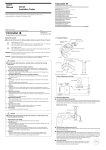
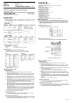
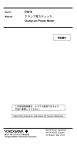
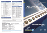
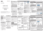
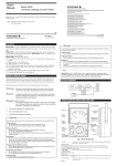
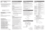
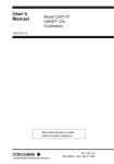
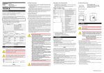
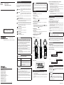
User’s
Manual
Models 30032A
Leakage Clamp-on Tester
Safety precautions
Various symbols are used on the instrument and throughout this manual to
ensure safe use of the product and to protect against possible hazards or
damage. The following safety symbols are used where appropriate. Read
the explanations carefully and familiarize yourself with the symbols before
reading the text.
Indicates a hazard that may result in the loss of life or
serious injury of the user unless the described instruction
is abided by.
Indicates a hazard that may result in an injury to the
CAUTION
user and/or physical damage to the product or other
equipment unless the described instruction is abided
by.
The following safety symbols are used on the instrument and in this
manual:
WARNING
Danger! Handle with Care
WARNING
This symbol indicates that the operator must refer to an explanation
in the instruction manual in order to avoid the risk of injury or death
of personnel or damage to the instrument.
Store this manual in a safe
place for future reference.
IM 30032A-E
1st Edition: May 2008
Copyright May 2008(YMI). 1st Edition; May 2008(KP)
This symbol indicates that this instrument designed to be applied
around or removed from HAZARDOUS LIVE conductors provided
if the RATED circuit-to-earth voltage dose not exceed the value
indicated in the measurement category.
Double Insulation
This symbol indicates double insulation.
Alternating Current
This symbol indicates AC voltage/current.
Direct Current
This symbol indicates DC voltage/current.
Earth TERMINAL
This symbol indicates ground.
WARNING
n Strictly observe the following cautionary notes in order to
avoid the risk of injury or death of personnel or damage to
the instrument due to hazards such as electrical shock.
• Do not use the instrument if there is any damage to the casing, battery cover, display and labels or when the casing is removed.
• Barrier is for to avoid touching the conductor.
Be careful not to across the Barrier when using the instrument.
• Disconnect the instrument from the measurable conductors under
test before opening the casing to replace the battery.
• Safety protectors such as rubber-insulated gloves should be worn to
prevent electrical shock when using the instrument.
• Avoid using the instrument if it has been exposed to rain or moisture
or if your hands are wet.
• Do not use the instrument in an atmosphere where any flammable
or explosive gas is present.
CAUTION
• The jaw section is a delicate, precision sensor. Do not subject the
jaw to unreasonably strong shock, vibration, or force when using
it.
• If dust gets into the tops of the jaws, remove it immediately. Do not
close the jaws when dust is trapped in its joints as the sensor may
break.
Components
1)Jaw Section
Is a precision sensor for detecting currents.
2)Open/Close Lever
Opens and closes the jaws.
n When the AUTO POWER OFF Function is not Used
(Cancellation of the AUTO POWER OFF Function)
• Turn off the power.
• With the DATA HOLD switch held down, press the POWER switch
for more than 2 sec. to turn on the power.
This causes the buzzer to sound, canceling the AUTO POWER OFF
function (the AUTO OFF display goes off).
If the instrument is used with the AUTO POWER OFF function cancelled, take care not to let the battery run down.
n Recovering the AUTO POWER OFF Function
• Turn off the power.
• Turn on the power. This enables the AUTO POWER OFF function to
recover. (AUTO OFF appears.)
Measuring Instructions
3)Display
Shows the measured value (digital reading or bar graph), unit, function
and low-battery symbol (
), etc.
4)mA/A Selector Switch
Selects the unit of AC current (either “mA” or “A”) to be measured.
5)Data Hold Switch
Retains the measured data. If you press this switch, the
symbol appears and the data is retained. If you press this switch once again, data
holding is canceled (the
symbol disappears).
6)Power Switch
Turns on the power to the instrument.
7)Filter Switch
Turns on/off the filter. Press the FILTER switch for more than 2 sec.
When the filter is on (used), appears.
8)Battery Housing (Battery cover)
Contains the battery.
n Before
������������������
measurement
a)Examine the casing, battery cover, display, and labels of the instrument
for abnormalities.
b)Make sure that the battery cover is firmly closed.
n AC Current Measurement (unit: mA/A)
a)Press the POWER switch to turn on the power.
b)Squeeze the open/close lever to open the jaws. Insert a wire from the
measurable conductors under test through the jaws, making sure the tops
of the jaws are tightly shut.
c)When the reading stabilizes, read the value. If you have difficulties in
reading the value, use the DATA HOLD function.
d)When measuring Load Current, press the mA/A switch to change to A
range.
e) When you have finished measurement, press the POWER switch to turn
off the tester.
CAUTION
• The correct measured values are not displayed if the jaws do not fit
precisely. Make sure that they are shut tightly.
n Using the DATA HOLD switch
Pressing the DATA HOLD switch retains the measured data and displays
. The mA/A selector switch and the FILTER switch cannot be used in
this situation. The only switches that can be used are the DATA HOLD
switch (to cancel data holding) and the POWER switch.
9)Barrier
Prevents contact with the wires.
Range Selection
Barrier
Open/
close lever
Jaw
section
Filter
switch
mA/A
selector
switch
Display
Data hold
switch
Power
switch
n Range Selection
Switching between the 3 mA and 30 mA ranges and between the 30 A and
60 A ranges is performed by auto-ranging (automatic). For switching between the 3/30 mA and 30/60 A ranges, the range must be switched using
the mA/A selector switch.
n Measurement Ranges
60 A range
Battery
housing
(cover)
Measurement Category of Model 30032A
Measurement
category (CAT.)
III
Maximum Allowable Input
62 Arms
(The RATED circuit-to-earth voltage: 300 Vrms AC)
Do not apply input exceeding this value. Otherwise,
it will not only damage the tester, but also pose a risk
of damage to the human body. For safety standards,
refer to the specifications.
International Sales Dept.
Tachihi Bld. No.2, 6-1-3, Sakaecho, Tachikawa-shi,Tokyo 190-8586 Japan
Phone: 81-42-534-1413, Facsimile: 81-42-534-1426
YOKOGAWA CORPORATION OF AMERICA (U.S.A.)
Phone: 1-800-888-6400 Facsimile: 1-770-254-0928
YOKOGAWA EUROPE B. V. (THE NETHERLANDS)
Phone: 31-33-464-1611 Facsimile: 31-33-464-1610
YOKOGAWA AMERICA DO SUL LTDA. (BRAZIL)
Phone: 55-11-5681-2400 Facsimile: 55-11-5681-4434
YOKOGAWA ENGINEERING ASIA PTE. LTD. (SINGAPORE)
Phone: 65-6241-9933 Facsimile: 65-6241-2606
YOKOGAWA MEASURING INSTRUMENTS KOREA CORPORATION (KOREA)
Phone: 82-2-551-0660 to -0664 Facsimile: 82-2-551-0665
YOKOGAWA AUSTRALIA PTY. LTD. (AUSTRALIA)
Phone: 61-2-8870-1100 Facsimile: 61-2-8870-1111
YOKOGAWA INDIA LTD. (INDIA)
Phone: 91-80-4158-6000 Facsimile: 91-80-2852-1441
YOKOGAWA SHANGHAI TRADING CO., LTD. (CHINA)
Phone: 86-21-6239-6363 Facsimile: 86-21-6880-4987
Range down
Range up
I≥32.70A
0.05A<I
I≥32.70mA
I≤2.88mA
OL
30 mA range
Display (LCD)
Zero correction
3 mA range
Overrange
0.00A
Hand strap
Range down
Range up
Overrange
0.000mA
0.010mA<I
I≥3.270mA
Battery Replacement
CAUTION
• Do not use the instrument near noise-emitting equipment or where
there may be sudden changes in temperature. Otherwise, the instrument may produce an unstable readings or errors.
• Do not wipe the instrument using an organic solvent such as benzine
or paint thinner. Otherwise, the front panel may be damaged or
discolored. When cleaning the instrument, use a dry cloth.
• Do not leave the tester exposed to direct sunlight or in a hot and
humid location such as the inside of a car, for any prolonged length
of time.
• If the instrument will not be used for long periods, remove the battery.
Yokogawa Meters & Instruments Corporation
30 A range
62.0A MAX
OL
Zero correction
WARNING
I≥60.6A
I≤28.8A
AUTO POWER OFF Function
n When the AUTO POWER OFF Function is Used
• AUTO OFF appears.
• The instrument automatically turns off 10 minutes after the last switch
operation. A buzzer starts to beep 15 seconds before the automatic
power-off.
• Pressing any switch after the beep restarts the auto power-off function.
n Battery
�������� Voltage
�������
If the battery runs down and its voltage falls below the operating voltage
(effective range), the
symbol appears in the LCD display; promptly
replace the battery with a new one.
(Battery: CR2032, 1 pc.)
CAUTION
• The specified accuracy is assured when the battery voltage is in the
effective range.
If the
symbol is displayed, promptly replace the battery.
• If the power does not come on even after pressing the POWER
switch, the battery voltage may have fallen too low. Replace the
battery with a new one.
YOKOGAWA MIDDLE EAST B. S. C (C) (BAHRAIN)
Phone: 973-17-358100 Facsimile: 973-17-336100
YOKOGAWA ELECTRIC CIS LTD. (RUSSIAN FEDERATION)
Phone: 7-495-737-7868 Facsimile: 7-495-737-7869
IM3E-2008.8
IM 30032A-E <1>
CAUTION
• Before replacing the battery, always disconnect the tester from the
measurable conductor under test because there is a risk of electrical shock. After replacement, close the battery cover securely and
conduct measurements.
• Use the specified lithium battery (CR2032).
To replace the battery:
a) Press the POWER switch to turn off the power.
b) Turn the battery cover on the backside of the instrument in the direction
of the arrow using a coin, etc.
c) Remove the cover and the battery.
d) Insert a new battery, making sure that the polarities are correct.
e)Close the cover back in place by turning it in the reverse direction of the
arrow.
Inserting a Battery
Closing the Battery Cover
Insert the battery being careful
that the polarities are correct.
Close the battery cover, aligning
the arrow's tail with the dot and
then turn clockwise.
Filtering Function
The instrument has a function for turning the filter on (use)/off. Press the
FILTER switch for more than 2 sec. to turn it on/off (default: ON). When
the filter is on, the
symbol appears.
When the FILTER switch is turned on, the sharp filter is enabled. This filter
attenuates 2nd-order and higher harmonic currents and measures only the
fundamental harmonics. See the Filtering Characteristics below.
30032A Filtering characteristics
10
0
Ampritude ratio [dB]
n Replacing
���������������������
the Battery
-10
-20
-30
-40
-50
-60
-70
-80
0
50
100
150
Frequency [Hz]
Battery cover
Examples of Measurement
n Examples of Leakage Current Measurement
Load
(3)
Load
(1)
Single-phase
Two-wire Circuit
Load
(2)
Grounding Wire
Single-phase Threewire or Three-phase
Three-wire Circuit
n To Ensure Accurate Measurement
The maximum input current of the harmonic components in the 3 mA and
30 mA ranges is 150 mA.
If the input exceeds 150 mA, the correct value is not displayed. In some
cases, “0L” does not appear and an error becomes larger or readings do
not change.
Therefore, follow the procedure below to check if the current under measurement including 2nd-order and higher harmonic components exceeds
150 mA.
Checking procedure:
1. Press the mA/A selector switch to choose the 30 A range.
2. Press the FILTER switch to select FILTER OFF and conduct measurement.
3. Check that the measured value (reading) in the 30 A range is 0.15 A* or
less.
4. When the measured value is 0.15 A or less, switch the range to 3 mA/30
mA and conduct measurement.
*: The accuracy of the 30 A range is 1.0% of reading +5 digits
(0.05A < I ≤ 50 A).
Five digits are equivalent to 0.05 A; when checking the current, also
consider the accuracy.
Specifications (30032A)
n Specifications
Condition: temperature and humidity
23 ˚C ±5 ˚C, 80% RH or less
Frequency������������������������������
:
����������������������������
50 Hz ±1.0 Hz, 60 Hz ±1.0 Hz
Battery voltage: Within the effective range
AC current measurement
Accuracy: ± (% of reading + digits)
Filter function OFF
Load
n Example of Load Current Measurement
Range
Resolution
Maximum
Allowable Current
Accuracy
3 mA
0.001 mA
30 mA
0.01 mA
30 A
0.01 A
0.05 < I ≤ 50.0 A: 1.0% +5 32.70 A
60 A
0.1 A
50.0 < I ≤ 60.6 A: 5.0% +5 60.6 A
0.010 < I ≤ 32.70 mA:
1.0%+5
3.270 mA
32.70 mA
Filter function ON
Range
Insert only one of the wires through the jaws.
Resolution
WARNING
Measurement Category (CAT.)
Measurement
category
Description
Remarks
I
CAT.I
For measurements performed on circuits
not directly connected to MAINS.
II
CAT.II
For measurements performed on circuits Appliances,portable
directly connected to the low-voltage
equipments,etc.
installation.
III
CAT.III
For measurements performed in the
building installation.
Distribution board,
circuit breaker,etc.
IV
CAT.IV
For measurements performed at the
source of the low-voltage installation.
Overhead wire,
cable systems,etc.
Internal Wiring
Entrance
Cable
CAT. IV
Distribution
Board
CAT. III CAT. II
T
CAT. I
Fixed Equipment,
etc.
Outlet
Equipment
Disposing the Product
Waste Electrical and Electronic Equipment (WEEE)
Directive 2002/96/EC
This Product complies with the WEEE Directive (2002/96/EC) marking requirement. The affixed product label (see below) indicates that you must not
discard this electrical/electronic product in domestic household waste.
Product Category
With reference to the equipment types in the WEEE directive Annex 1,
this product is classified as a “Monitoring and Control instrumentation”
product.
To return unwanted products within the EU area, contact your local
Yokogawa Europe B.V. office.
Do not dispose in domestic household waste.
“Measures for Administration of the Pollution Control of
Electronic Information Products” of the People’s Republic
of China
The following are the provisions of “Measures for Administration of the
Pollution Control of Electronic Information Products” of the People’s
Republic of China.
They are applicable only in the People’s Republic of China.
产品中有毒有害物质或元素的名称及含量
有毒有害物质
部件名称
电流探头
( 夹子 )
铅
(Pb)
汞
(Hg)
镉
(Cd)
六价铬
(Cr (VI))
多溴联苯
(PBB)
多溴二苯醚
(PBDE)
×
×
×
×
○
○
○:表示该部件的所有均质材料中的有毒有害物质的含量均在 SJ/T11363-2006 标准中所规定的
Maximum
Allowable Current
Accuracy
3 mA
0.001 mA
30 mA
0.01 mA
30 A
0.01 A
0.05 < I ≤ 50.0 A: 1.5%+5
32.70 A
60 A
0.1 A
50.0 <I ≤ 60.6 A: 5.5% +5
60.6 A
n General Specifications
•Method: Mean-value detection and rms-value calibration
•Display (LCD): Digital reading ........ 3200 counts
Bar graph ................ 32 segments
“OL” over-range indication
low-battery symbol
data hold symbol
“AUTO OFF” auto power off indication
filter ON
•Sampling:
Digital reading ........ 2 times/sec
Bar graph ................ 12 times/sec
•Range:
3 mA, 30 mA, 30 A, 60 A
•Range selection: Automatic (between 3 mA and 30 mA ranges and between 30 A and 60 A ranges)
Manual (between 3 mA and 30 mA ranges and between
30 A and 60 A ranges)
•Additional functions:
Data hold and Auto power-off
•Operating temperature and humidity range:
0 to 50°C, with a maximum humidity of 80% RH or less
(no condensation)
•Storage temperature and humidity range:
-20 to 60°C, with humidity range is 20 to 70%RH (no
condensation)
•Temperature coefficient:
The following values must be added in the temperature
range of either 0 to 18°C or 28 to 50°C.
0 ≤ I ≤ 50.0A: ���������������������������������������
± �������������������������������������
(0.08% of reading/˚C + 0.5 digits/˚C)
50.0 < I ≤ 60.6A: ��������������������������������������
± ������������������������������������
(0.3% of reading/˚C + 0.5 digits/˚C)
•Effect of external magnetic fields:
0.0005% typical value (in terms of the magnitude of
current in adjacent wires)
•Diameter of measurable conductors: Ø 40 mm (Maximum)
•The RATED circuit-to-earth voltage: 300 Vrms or less
•Withstanding voltage: 3.7 kV AC for one minute (Tested between the
cores of the jaw section and the case)
•Power consumption: 6mW maximum
•Automatic power-off: Automatically turns of the power approx. 10 minutes
after the last switch operation. (The alarm buzzer begins
beeping 15 seconds before power-off.)
•Power supply: CR2032 lithium battery...................... 1
•Battery life:
Approx. 90 hours (of continuous operation)
•Dimensions:
Approx. 70 (W) x 178 (H) x 25 (D) (mm),
excluding protrusions
•Weight:
Approx. 200 g (including the battery)
•Accessories:
Battery (housed in the instrument)...... 1
RB057 soft carrying case.................... 1
User’s manual
•Safety standards:Complaint with EN 61010-1, EN 61010-2-032
Measurement category III
(The RATED circuit-to-earth voltage: 300 Vrms AC)
Pollution degree2
Environmental conditions:
Operating altitude: 2000 m max. above sea level;
indoor use
•EMC standards: EN 55011, EN 61326-1 (Class B, Group 1)
•Effect of radiation immunity:
Accuracy range of reading (Rated accuracy +4.0% of
each range) for the strength of a radio-frequency electromagnetic field of 3v/m.
0.010 < I ≤ 32.70 mA:
1.5 %+5
3.270 mA
32.70 mA
Note: Input current of 2nd-order and higher harmonics
: 150 mA rms maximum in the 3 mA/30 mA range
: 62 A rms maximum in the 30 A/60 A range
Filter specifications
(3 mA and 30 mA ranges and 30 A and 60 A ranges)
Amplitude ratio at 100 Hz: -38 dB (1.26%) or less (typical: -41 dB)
Amplitude ratio at 120 Hz: -53 dB (0.22%) or less (typical: -56 dB)
Zero correction
3 mA range: Displays 0.000 mA (zero) when 0.010 mA < I
30 A range: Displays 0.00 A (zero) when 0.05 A < I
限量以下。
×:表示该部件中至少有一种均质材料中的有毒有害物质或元素的含量超过 SJ/T11363-2006 标准
所规定的限量要求。
环保使用期限 :
该 标 识 适 用 于 2006 年 2 月 28 日 颁 布 的《 电 子 信 息 产 品 污 染 控 制 管 理 办 法 》 以 及
SJ /T11364 – 2006《电子信息产品污染控制标识要求》中所述,在中华人民共和国销
售的电子信息产品的环保使用期限。
只要您遵守该产品相关的安全及使用注意事项,在自制造日起算的年限内,则不会因
产品中有害物质泄漏或突发变异,而造成对环境的污染或对人体及财产产生恶劣影响。
注)该年数为“环保使用期限"
,并非产品的质量保证期。零件更换的推荐周期,请参
照使用说明书。
IM 30032A-E <2>