1
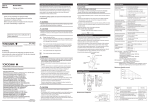
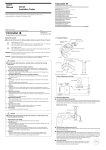
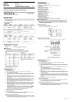
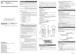
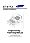
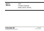
User's Manual Model 3226 Universal Leakage Current Tester Yokogawa Meters & Instruments Corporation International Sales Dept. Tachihi Bld. No.2, 6-1-3, Sakaecho, Tachikawa-shi,Tokyo 190-8586 Japan Phone: 81-42-534-1413, Facsimile: 81-42-534-1426 YOKOGAWA CORPORATION OF AMERICA (U.S.A.) Phone: 1-770-253-7000 Facsimile: 1-770-251-2088 Read this user’s manual before using the instrument in order to fully and correctly utilize all its functions. YOKOGAWA EUROPE B. V. (THE NETHERLANDS) Phone: 31-334-64-1611 Facsimile: 31-334-64-1610 YOKOGAWA ENGINEERING ASIA PTE. LTD. (SINGAPORE) Phone: 65-6241-9933 Facsimile: 65-6241-2606 Model: 322610 Universal Leakage Current Tester 322710 Test Box YOKOGAWA AMERICA DO SUL S. A. (BRAZIL) Phone: 55-11-5681-2400 Facsimile: 55-11-5681-1274 YOKOGAWA MEASURING INSTRUMENTS KOREA CORPORATION (KOREA) Phone: 82-2-551-0660 to -0664 Facsimile: 82-2-551-0665 YOKOGAWA AUSTRALIA PTY. LTD. (AUSTRALIA) Phone: 61-2-9805-0699 Facsimile: 61-2-9888-1844 YOKOGAWA INDIA LTD. (INDIA) Phone: 91-80-4158-6000 Facsimile: 91-80-2852-1441 YOKOGAWA SHANGHAI TRADING CO., LTD. (CHINA) Phone: 86-21-6880-8107 Facsimile: 86-21-6880-4987 YOKOGAWA MIDDLE EAST E. C. (BAHRAIN) Phone: 973-358100 Facsimile: 973-336100 A3 LTD. YOKOGAWA ELECTRIC (RUSSIAN FEDERATION) Phone: 7-095-737-7868 Facsimile: 7-095-737-7869 IM3E-2006.2 IM 3226-E Printed in Japan Nov. 2007 5th (KP) GENERAL Model 3226 is a special milliammeter for measuring leakage current of electrical appliances. The input resistance can be selected from among 1, 1.5 and 2 KΩ for easy measurement. Model 3226 is usable for product inspection on production lines and for experimental measurement in research and design activities. Model 3227 Test Box is available for the convenience of measurement. Model 3226 has the following features: (1) 4-way function: AC current, DC current, DC + AC current and AC voltage are measurable. (2) High accuracy: ±2.5% of full scale. (3) High sensitivity: 0.1 mA for full scale. (4) TAUT BAND system meter free of friction and strong against vibration and shock. (5) Overload protective circuit to prevent the meter coil from burning and the meter pointer from bending (6) Shielded case to eliminate effect of external high-frequency electric field. (7) Compact and lightweight for easy portable use. SAFETY PRECAUTIONS When operating the instrument, be sure to observe the cautionary notes given below to ensure correct and safe use of the instrument. Yokogawa is by no means liable for any damage resulting from use of the instrument in contradiction to these cautionary notes. Caution To avoid injury of personnel or damage to the instrument, carefully observe and follow the cautions listed below: Measurement Do not apply a voltage and current over the allowable limits between the terminals. Selector switch Do not switch the Measuring range selector switch during measurements. Batteries -Do not use different types of batteries together or new and old batteries together. -If the instrument is not used for a long period, store the instrument with the batteries removed. Otherwise, any leakage from the batteries may damage the instrument. Note Model 3226 has AC + DCmA range. This is used mainly for the instrument which is operated by DC after rectifing, AC to DC. Therefore, measured value on this range does not indicate RMS value, but the sum of DC and AC components directly. BLOCK DIAGRAM The following safety symbols are used on the instrument and in this manual. Warning Caution This symbol indicates AC voltage/current. This symbol indicates a Fuse. This symbol indicates ground(earth). Warning To avoid injury, death of personnel, carefully observe and follow the warnings listed below: Measurement -Do not operate the instrument over 250 V of strong electric circuit. -Do not touch the Input (Output) terminals, when measuring voltage. Measuring lead -Use the lead supplied by Yokogawa for the instrument concerned. -Do not use a deteriorated or damaged lead. -Do not attach/detach the lead to /from the instrument prior to releasing it from the measured object. Protection -Be sure to use the designated fuse (Rating: voltage, current and type) to prevent fire. -If there are any cracks or other damage in the case because of being dropped or struck, the instrument may not be safety insulated. Do not use the instrument before any remedial measures are taken. Replacement of batteries or fuse -Prior to detaching the cover for replacing the batteries or fuse, release the lead from the measured object and turn off the switch. Operating Environment -Do not operate the instrument in a flammable or explosive gas atmosphere. -Do not operate the instrument if there is condensation on it. Disassembly -Do not attempt to disassemble the instrument. Operating amplifier 200 µA F.S. Internal resistance: 121 Ω Overload protective circuit Battery check circuit Indicates a hazard that may result in an injury to the user and/or physical damage to the product or other equipment unless the described instruction is abided by. Danger! Handle with Care. This symbol indicates that the operator must refer to an explanation in the User’s Manual in order to avoid risk of injury or death of personnel or damage to the instrument. Input resistance selector circuit Range selector circuit Indicates a hazard that may result in the loss of life or serious injury of the user unless the described instruction is abided by. Moving-coil type DC milliammeter PARTS IDENTIFICATION AND FUNCTION 6. Scale plate 1. B mark B 0 2. Spear pointer AC+DCmA 10 1 1kΩ 1.5kΩ 5. Power on-off/battery check switch B 90 180 8 10 12 2400 7. Carrying handle 1 30 50 ACV 0 8. Meter cover fixing screw 9. Meter cover 3. Zero adjuster screw 4. Input resistance switch 6 4 2 2kΩ INPUT RESISTANCE BATT 10 1 0.1 0.1 10 300 ON 1 OFF DCmA 10. Measuring range selector switch ACmA INPUT 11. Input terminals 150 0.1 ACV 12. Case Fig. 1 Parts Identification 1. B mark: The battery is usable if the meter pointer is within this range when the BATT/ON/OFF switch is set to the BATT position. 2. Spear pointer 3. Zero adjuster screw:To be turned with a screwdriver for readjusting zero indication of the pointer. 4. lnput resistance switch: Selects one of the three input resistances according to the applicable standard. 5. Power on-off/battery check switch 6. Scale plate: The scale is double graduated in mA and AC V. 7. Carrying handle 8. Meter cover fixing screw 9. Meter cover 10.Measuring range selector switch: To be set to an appropriate position according to the measuring item and range. 11.lnput terminals: Accessory H-lead is to be connected to the “INPUT” terminal, and L-lead to the “ ” (ground) terminal. 12.Case OPERATION SPECIFICATIONS Precautions: 1. The most accurate measurement is attained when Model 3226 is placed horizontally. 2. After placing Model 3226 at the position of use, check that the meter pointer coincides with the zero point of the scale, if not, adjust it accurately by turning the zero adjuster screw. 3. When the approximate value of the leakage current to be measured is unpredictable, measure by first setting the measuring range selector switch to the 10 mA position. 4. Before measurement, be sure to check that the measuring range selector switch is in a position proper for the measurement. Do not operate the switch while the meter pointer is deflecting. 5. When storing of carrying Model 3226 after use, set power on-off/battery check switch. When using Model 322710 Test Box: Model 322610 Measuring ranges: DC current: AC current: DC+AC current: AC voltage: Input resistance: Current measuring range: Voltage measuring range: Working frequency range: Overload protection: Effect of temperature: Warning Before using this instrument, it is necessary to match the polarity with that of the power plug. Applying 100 V AC to the cabinet of the appliance to be tested without matching the polarities may cause an electric shock. Insulation resistance: Withstand voltage: Matching the polarity Connect the power cord to the power supply. Turn the power switch to ON and measure the voltage between the earth and the TEST terminal of this instrument using a Universal leakage voltage tester (3226 or similar). If the voltage between the earth and the TEST terminal of this instrument is -AC30 V or less: the instrument can be used; -More than AC30 V: use the accessory 3-2 pin adapter and reconnect the power plug opposite (i.e. turning 180 degrees). Power source: Outside dimensions: 1. Set the power ON–OFF/battery check switch to the “BATT” position and check the condition of the battery. If the meter pointer is within the battery check-line range, set the switch to the “ON” position. (If the meter pointer is not within the battery checkline range, remove the back cover and change the batteries.) 2. Set the measuring range selector switch to ACV position of Model 3226. Connect the ground terminal of Model 3226 to the TEST terminal of Model 3227, then close switch S1. 3. Connect the “INPUT” terminal (H) of Model 3226 to either of the connector C1 of Model 3227, and measure the power voltage to check that the voltage is as rated. (If the polarity is opposite, the meter pointer will be zero; in this case use switch S2 to change the polarity.) 4. Open switch S1, and connect all the simultaneously accessible exposed conductive surfaces of the to-be-tested appliance together to the “INPUT” terminal (H) of Model 3226. 5. Input power plug P2 of the to-be-tested appliance, and turn on all the appliance’s switches. 6. Leakage current is not necessarily only in the AC spectrum, therefore set the measuring range selector switch to AC + DC mA range. 7. Close switch S1 of Model 3227, and read the meter of Model 3226. This reading will tell you the approximate value of the leakage current. 8. Referring to the value obtained in number 7. above, set the range of the ACmA to the optimum range, and read the meter of Model 3226. 9. Change switch S2 of Model 3227, read the meter of Model 3226, and use the greater one of the above meter readings as the leakage current value. 10. Set the measuring range selector switch of Model 3226 to the DCmA range, and read the meter of Model 3226. 11. Repeat the measurement conducted in number 9. above. 12. Start operating the appliance. When the appliance has reached its steady operating status, measure its leakage current. When not using the Model 3227 Test Box, compose a circuit similar to that shown in Figure 2 and measure. Model 322710 Current capacity: Contact resistance: Insulation resistance: ON ON Appliance to be tested Power plug P2 Power plug P1 connecter C1 3226 Ground open TEST Withstand voltage: Outside dimensions: Weight: Accessories: 1, 1.5 and 2 KΩ Higher than 100 KΩ 20 Hz to 5 kHz Withstands 30 mA AC for 10 minutes for each current measuring range. Less than ±0.2%/°C with respect to rated value (within 20 ±10°C) Higher than 100 MΩ at 1000 V DC between electric circuit and case. 1500 V AC (50 Hz) for 1 minute between electric circuit and case. Two 9 V dry batteries 6F22. Usable for approx: 290 hour. Approx. 190×124×90 mm (7-1/2 × 4-7/8 × 3-9/16”), excluding carrying handle. Approx.1 kg (2.2 lbs) Measuring lead, (B9607GT) 1 Carrying bag (B9646BU) User’s manual 1 10 A AC (125 V) Lower than 0.005 Ω Higher than 100 MΩ at 500 V DC between the electric circuit and the case. 1000 V AC for 1 minute between the electric circuit and the case. Approx. 70×155×65 mm Approx. 0.6 kg 3 to 2 pin adapter Model 3227 Test Box MAINTENANCE Model 3227 S1(POWER) S2(POLARITY) OFF ON Weight: Accessories: 0.1, 1 and 10 mA 0.1, 1 and 10 mA 0.1, 1 and 10 mA 150 and 300 V (50 or 60 Hz) Insulation Table Fig. 2 Connection Diagram CALIBRATION 1. Instruments necessary for calibration Instrument Requirements YOKOGAWA equivalent Standard DC power supply Output: 10 mA Accuracy: 0.5 % Model 2552 Standard AC power supply Output: 10 mA Accuracy: 0.5 % Model 2558 2. Procedure 1 Set the input resistance to 1 KΩ by using the input resistance switch of Model 3226. 2 Set the power on-off/battery check switch to the “ON’’ position, and adjust the meter pointer to the zero point of the scale by using the variable resistor RV2 inside the case. 3 Set the measuring range selector switch to the DC 1 mA position, supply 1 mA from the standard PC power supply, and adjust the RV1 variable resistor inside the case so that the meter is showing the full scale. 4 Conduct adjustment in the same manner as above, while the measuring range selector switch is set to DC 10 mA, AC 1 mA and AC 10 mA positions in sequence. If indication error is large, test and adjust for the most uniform and highest accuracy of all the measuring ranges. 5 Repeat the foregoing, with the input resistance set to 1.5 and 2 KΩ in sequence. For accurate measurement at all times, Model 3226 must be kept in the best condition. For this purpose, avoid using Model 3226 at a place subject to: (1) Severe vibration (2) Fill of dust or corrosive gas (3) Direct sunlight (4) Much moisture (5) Large variation of ambient temperature (6) Strong external magnetic field - Both surfaces of the meter cover are coated with anti-static agent. Do not wipe them hard or clean them with wet cloth, because such may deteriorate the anti-static effect. (Use dry, soft cloth, and wipe them lightly with it.) - The case and meter cover are made of thermoplastic material. Be careful not to touch them with a soldering iron or other hot object. Do not clean them with a large quantity of lacquer thinner, benzine or alcohol. Disposing the Product Waste Electrical and Electronic Equipment (WEEE) Directive 2002/96/EC This Product complies with the WEEE Directive (2002/96/EC) marking requirement. The affixed product label (see below) indicates that you must not discard this electrical/ electronic product in domestic household waste. Product Category With reference to the equipment types in the WEEE directive Annex 1, this product is classified as a “Monitoring and Control instrumentation” product. To return unwanted products within the EU area, contact your local Yokogawa Europe B. V. office. Do not dispose in domestic household waste.