1
18 HP SKID MOUNT
8184-04-01
18 HP SWING ARM
PARTS / OPERATOR’S MANUAL
Original Language Instructions
Rev. A 07-2014
MAN 100102
MODELS:
8183-04-01
CALIFORNIA
WARNING
Proposition 65 Warning
Diesel engine exhaust and some
of its constituents are known to the
State of California to cause cancer,
birth defects and other reproductive
harm.
The engine exhaust from this product
contains chemicals known to the State
of California to cause cancer, birth
defects or other reproductive harm.
CALIFORNIA
Proposition 65 Warning
Battery posts, terminals, wiring
insulation, and related accessories
contain lead and lead compounds,
chemicals known to the State of
California to cause cancer and birth
defects or other reproductive harm.
WASH HANDS AFTER HANDLING.
TRUCKLOADER
IMPORTANT MESSAGE
On behalf of everyone at Little Wonder, we would like to thank you for your purchase of a Little Wonder TruckLoader.
This professional truckloader was designed to the highest standards to ensure many hours of uninterrupted service.
This machine comes with an Operators / Parts Manual. The useful life and good service you receive from this machine
depends to a large extent on how well you read and understand this manual. Treat your machine properly, lubricate and
adjust it as instructed, and it will give you many years of reliable service.
Your safe use of this Little Wonder product is one of our prime design objectives. Many safety features are built in, but we also
rely on your good sense and care to achieve accident-free operation. For best protection, study the manual thoroughly. Learn
the proper operation of all controls. Observe all safety precautions. Follow all instructions and warnings. Do not remove or
defeat any safety features. Make sure those who operate this machine are as well informed and careful in its use as you are.
See a Little Wonder dealer for any service or parts needed. Little Wonder service ensures that you continue to receive
the best results possible from Little Wonder products. You can trust Little Wonder replacement parts because they are
manufactured with the same high precision and quality as the original parts.
Little Wonder designs and builds its equipment to serve many years in a safe and productive manner. For longest life,
use this machine only as directed in the manuals, keep it in good repair and follow safety warnings and instructions. You'll
always be glad you did.
Little Wonder
1028 Street Rd.
Southampton, PA 18966
TABLE OF CONTENTS
FIGURES
PAGE
SAFETY..........................................................................................................................................................2-6
LABELS............................................................................................................................................................. 7
SET-UP INSTRUCTIONS.............................................................................................................................8-10
CONTROLS..................................................................................................................................................... 11
OPERATION...............................................................................................................................................12-13
MAINTENANCE / STORAGE.......................................................................................................................... 14
SPECIFICATIONS........................................................................................................................................... 15
PARTS SECTION.......................................................................................................................................16-17
WARRANTY................................................................................................................................ BACK COVER
07-2014
1
SAFETY
TRUCKLOADER
NOTICE !!!
Unauthorized modifications may present extreme
safety hazards to operators and bystanders and
could also result in product damage.
Little Wonder strongly warns against, rejects and
disclaims any modifications, add-on accessories or
product alterations that are not designed, developed,
tested and approved by Little Wonder Engineering
Department. Any Little Wonder product that is altered,
modified or changed in any manner not specifically
authorized after original manufacture–including the
addition of “aftermarket” accessories or component
parts not specifically approved by Little Wonder–will
result in the Little Wonder warranty being voided.
Any and all liability for personal injury and/or property
damage caused by any unauthorized modifications,
add-on accessories or products not approved by
Little Wonder will be considered the responsibility
of the individual(s) or company designing and/or
making such changes. Little Wonder will vigorously
pursue full indemnification and costs from any party
responsible for such unauthorized post-manufacture
modifications and/or accessories should personal
injury and/or property damage result.
This symbol means:
ATTENTION!
BECOME ALERT!
Your safety and the safety of others is involved.
Signal word definitions:
The signal words below are used to identify levels
of hazard seriousness. These words appear in this
manual and on the safety labels attached to Little
Wonder machines. For your safety and the safety
of others, read and follow the information given with
these signal words and/or the symbol shown above.
DANGER indicates an imminently hazardous
situation which, if not avoided, WILL result in death
or serious injury.
WARNING indicates a potentially hazardous
situation which, if not avoided, COULD result in
death or serious injury.
CAUTION indicates a potentially hazardous situation
which, if not avoided, MAY result in minor or moderate
injury. It may also be used to alert against unsafe
practices or property damage.
Schiller Grounds Care, Inc.
1028 Street Road
Southampton, PA 18966 U.S.A
Phone: 215-357-5110
Fax: 215-357-8045
MODEL NUMBER
2
SERIAL NUMBER
CAUTION used without the safety alert symbol
indicates a potentially hazardous situation which, if
not avoided, MAY result in property damage
MODEL NUMBER: This number appears on
sales literature, technical manuals and price lists.
SERIAL NUMBER: This number appears only
on your unit. It contains the model number
followed consecutively by the serial number.
Use this number when ordering parts or seeking
warranty information.
SAFETY
TRUCKLOADER
PREPARING FOR SAFE OPERATION
Operator preparation and training
Read the Operation & Safety
Manual
- If an operator or mechanic
cannot read English, it is
the owner's responsibility
to explain this material to
them. If any portion of this
material is unclear, contact
your factory representative for clarification.
-
Decals regarding safety and/or unit operations
have been placed on parts of the machine.
Adhere to the warnings and instructions depicted
in these decals. Replace any missing or
damaged labels.
- Become familiar with the safe operation of the
equipment, operator controls and safety signs.
Know how to stop the engine and attachments
quickly in an emergency. Do not operate or allow
another person to operate this machine if there
are any questions about safety.
-
-
All operators and mechanics should be trained.
The owner is responsible for training the users.
Never attempt to use a machine that is damaged
or has unauthorized modifications.
Wear appropriate clothing, including gloves.
Do not operate barefoot or when wearing open
sandals. Long hair, loose clothing or jewelry may
get tangled in moving parts.
-
Wear hearing protection.
-
Wear safety glasses.
-
Wear a dust mask to avoid breathing dust.
-
Never allow underage children, unskilled
or improperly trained people to operate this
equipment. Local regulations can restrict the age
of the operator. Never allow to ride, sit or stand
on machine.
- Keep warning labels and this operator's manual
legible and intact. Replacement labels and
manuals are available from the factory.
Site preparation and circumstances
-
If TruckLoader is mounted on a trailer, make
sure that the driver of the towing vehicle has the
operator of the TruckLoader in full view at all
times.
-
Check the area to be cleared of objects such
as rocks, toys, wire or other debris that may be
picked up or thrown by the machine.
-
Be sure the area is clear of pets and people,
especially young children. Never assume they
will remain where you last saw them. Stop the
machine if any enter the area.
-
Use machine only in daylight or in good artificial
light.
-
Evaluate the terrain to determine how to safely
perform the job. Only use accessories and
attachments approved by the manufacturer.
Machine preparation
-
Do not tamper with or defeat safety devices.
Keep guards, shields and interlock safety devices
in place and in proper working condition. They
are for your protection.
-
Keep all fasteners such as nuts, bolts and pins
well secured.
-
Verify that machine and attachments, if any, are
in good operating condition.
-
Do not start machine until ready to use.
-
Do not stand in front or behind machine.
Operator MUST stay on the side of the machine.
- Do not operate machine while under the
influence of drugs or alcohol.
-
The owner/user can prevent and is responsible
for accidents or injuries occurring to themselves,
other people or property.
3
SAFETY
TRUCKLOADER
OPERATION SAFETY
Interrupting operation
In general
-
Use extra care when loading or unloading the
truckloader onto a trailer or truck.
-
Before leaving the operator's position:
- Move throttle to the SLOW position.
- Shut off the engine and remove the key.
-
Slow down and use caution when making turns
and crossing roads and sidewalks.
-
-
Do not run the engine in an enclosed area where
dangerous carbon monoxide fumes can collect.
-
While operating the machine, maintain a safe
operating position, secure footing, and good
balance at all times.
-
Before operating, lower the discharge chute.
-
Keep a safe distance between two or more
operators when working together simultaneously.
-
Keep clear of the discharge opening at all times.
Never direct the discharge toward a bystander.
Stop operation if someone approaches.
-
Never leave a machine unattended. Always
turn off engine, set throttle to SLOW, key is in
OFF position, and fan has come to a complete
stop.
Move the throttle to the SLOW position, turn key
to the OFF position and wait till all moving parts
have come to a complete stop.
- before refueling;
Move the throttle to the SLOW position, turn key
to the OFF position, wait till all moving parts have
come to a complete stop and disconnect the
spark plug wire(s) or remove the key:
- before clearing blockages or unclogging chute;
- before checking, cleaning or working on the
machine;
- after striking a foreign object. Inspect the
machine for damage and make repairs before
restarting;
- if the machine begins to vibrate abnormally:
shut off machine immediately. Inspect and
make repairs as needed before restarting;
-
- except for repairs or adjustments as specifically
noted, such as for carburetor adjustment,
where the engine must be running. Keep
hands and feet clear of moving parts in these
circumstances.
-
Maintain machine according to manufacturer's
schedule and instructions for maximum safety
and best results.
-
Do not park machine on a steep grade or slope;
the machine can roll away causing personal
injury or damage to property.
-
Allow the fan to come to a complete stop when
stopping operation to clear blockages, unclog,
inspect the machine, do maintenance or repair.
-
Never look into the hose or discharge chute while
machine is running. Never operate machine
without suction hose attached properly.
-
Reduce the throttle setting to SLOW during
engine shut-down. Turn the key to the OFF
position.
Starting
-
Start only according to instructions in this manual
or on the machine.
-
When starting the engine, make sure hands and
feet are clear of the chute.
-
Do not start the machine while standing in front
of the discharge chute or with the chute directed
at someone.
-
Do not change engine governor settings or
overspeed the engine. Operating the engine
at excessive speed can increase the hazard of
personal injury.
4
SAFETY
TRUCKLOADER
MAINTENANCE SAFETY
In general
-
Maintain machine according to manufacturer's
schedule and instructions for maximum safety
and best results.
-
Park supporting vehicle on level ground.
-
Rotating Impeller: Do not attempt to remove materials from intake or discharge when truckloader
is running or impeller is still rotating.
-
Never allow untrained personnel to service machine.
-
Adjust or repair only after the engine has been
stopped and the fan has quit rotating.
-
Inspect truckloader components regularly. If
worn, damaged or deteriorated, they may expose
moving parts or allow objects to be thrown.
-
Replace parts if worn, damaged or faulty. Have
repairs made by a qualified Little Wonder dealer
or repairman. For best results, always replace
with parts recommended by the manufacturer(s).
-
Turn off engine, set throttle to SLOW position,
turn ignition key to OFF position. Disconnect
remove spark plug wire(s) before making any
repairs.
-
Disconnect the negative terminal first and the
positive last. Reconnect positive first and negative last.
-
Do not dismantle the machine without releasing
or restraining forces which may cause parts to
move suddenly.
Rotating Impeller
WARNING
-
Don't attempt to remove materials from intake or discharge
when unit is running or impeller
is rotating.
-
Fan coasts after the engine is
turned off.
-
Only replace impeller. Never straighten or weld
them.
-
Keep other persons away from impeller.
-
Caution should be used when clearing debris
from inside the housing. Gloves should be worn
as sharp edges on the impeller or in the debris
may be present.
Fuel
WARNING
-
Gasoline and diesel fuels are
flammable; gasoline vapors
are explosive. Use extra care
when handling.
-
Store only in containers
specifically designed for fuel.
-
When refueling or checking fuel level:
- Stop the engine and allow to cool;
- Do not smoke;
- Refuel outdoors only;
- Use a funnel;
- Do not overfill;
- If fuel is spilled, do not attempt to start the
engine until the spill is cleaned up and vapors
have cleared.
-
Provide adequate support, e.g. jack stands for
lifted machine or parts if working beneath.
-
Do not put hands or feet near or under rotating
parts.
-
Clean up spilled oil or fuel thoroughly.
Sparks from static electricity can start fires or cause
explosions. Flowing fuel can generate static
electricity. To prevent static electricity sparks:
- Keep containers electrically grounded. Do not fill
containers in a vehicle or on a truck or trailer bed
with a plastic liner. Fill containers on the ground
away from the vehicle.
-
Replace faulty mufflers.
-
When practical, remove gas powered equipment from the truck or trailer and refuel it on the
ground. If equipment must be refueled on the
truck or trailer, refuel from a portable container
rather than a dispenser nozzle.
-
Keep the dispenser nozzle in contact with the rim
of the fuel tank or container opening until fueling
is complete. Do not use a nozzle lock-open
device.
-
Replace caps on fuel cans and tanks securely.
-
If fuel is spilled on clothing change it immediately.
- To reduce fire hazards, keep the engine, muffler,
battery compartment and fuel storage area free
of grass, leaves, debris buildup or grease.
5
SAFETY
BATTERY
Battery acid is caustic and fumes
are explosive and can cause
serious injury or death.
TRUCKLOADER
WARNING
-
Keep the machine and fuel containers in a locked
storage place to prevent tampering and to keep
children from playing with them.
To reduce the risk of personal
injury when working near a battery:
-
Do not store the machine or fuel container near
heating appliances with an open flame such as a
water heater or an appliance with a pilot light.
- When working with battery
acid, use protective equipment
such as, but not limited to, goggles, face shield,
rubber gloves and apron.
-
Keep gasoline storage area free of grass, leaves
and excessive grease to reduce fire hazard.
-
-
Avoid leaning over a battery.
Clean grass and debris from cutting units, drives,
mufflers and engine to help prevent fires.
-
Do not expose a battery to open flames or
sparks.
-
-
Be sure batteries with filler caps are properly
filled with fluid.
When not in use store indoors in a sheltered area
(a dry place) where it is not accessible to children. DO NOT store in a house. Keep throttle in
SLOW position and ignition key in the OFF position.
-
Do not allow battery acid to contact eyes or skin.
Flush any contacted area with water immediately
and get medical help.
-
Do not check for spark with spark plug or plug
wire removed and grounded. Use an approved
tester. Sparks can ignite fumes.
-
Charge batteries in an open, well ventilated area,
away from sparks and flames. Unplug charger
before connecting or disconnecting from battery.
ENGINE
-
Don't run engine if there is an accumulation of
debris around the muffler and cooling fins.
-
Don’t run engine while electrical system causes
spark outside the cylinder.
-
Don't touch hot mufflers, cylinders or cooling fins
as contact may cause serious burns.
OIL
-
EQUIPMENT IS SHIPPED WITHOUT OIL! Refer
to engine manufacturers instruction manual for
instructions on filling the oil.
STORAGE AND TRANSPORTATION
-
Stop the engine and allow to cool before storing.
-
Drain the fuel tank outdoors only.
- Store fuel in an approved container in a cool, dry
place.
6
JUMP STARTING
1. Be sure the jumper cables are in good condition.
Turn off the ignition and all electrical accessories
on both machines.
2. Position the machine with a good (charged) battery next to but not touching the machine with the
dead battery so jumper cables will reach.
3. When making cable connections:
- Make sure the clamps do not touch anywhere
except to intended metal parts,
- Never connect a positive ("+" or red) terminal
to a negative ("–" or black) terminal.
- Make sure the cables won't get caught in any
parts after the engines are started.
4. Connect one end of the first jumper cable to the
positive terminal on one battery. Connect the
other end to the positive terminal on the other
battery.
5. Connect one end of the other cable to the
negative terminal of the machine with a good
(charged) battery. Make the final connection on
the engine of the machine to be started, away
from the battery.
6. Start the vehicle with the good battery, then the
machine with the discharged battery.
7. Remove the cables in the exact reverse order of
installation. When removing each clamp, take
care it does not touch any other metal parts while
the other end remains attached.
TRUCKLOADER
LABELS
P/N MP100108
P/N MP100109
7
SET UP INSTRUCTIONS
mbly Instructions
TRUCKLOADER
SKID MOUNT POWER UNIT
utions
1 – Power Unit: Includes Fuel Cell and Battery and Box
semble
1 – Discharge Stack Assembly (Stack / Elbow
kaging
Combination)
1 – 7” dia. X 30” Metal Discharge Hose
1 – 10’ Intake Hose (10” dia.)
1 – Intake Nozzle (10” dia.)
1 – Intake Nozzle Handle
1 – Intake Hose Connector
1 – Intake Hose Support Strap (10” dia.)
1 – Hose Support Boom, with Chain Guide
1 – Assembly Kit (Hardware, 2 – 10” Hose Clamps,
Support Chain, Metal Discharge Hose Clamp)
Battery (Dry without Acid)
1 – Operators Manual and Warranty Registration
package
1 – Engine Operation Manual
FIGURE 1
and protective packaging. Unfasten the power unit, discharge stack, and hitc
pallet.
Mount Swing Arm to receiver of vehicle.
unit utilizing the supplied
HITCH MOUNT
olts, washers,
andSWING
nuts.ARM
above with the addition of a 49” x 4” x 4”
power Same
unitas
are
for installing or removing
Swing
Arm
FIGURE 2
om hitch
mount / swing arm when
The truckloader is intended to be used in conjunction
with a truck or trailer mounted debris receptacle to
ch is available.
y
load landscape debris for removal from a work site to
storage, dump or processing site. These receptacles
or debris bodies or boxes are provided by the user and
are the responsibility of the user.
SET UP INSTRUCTIONS
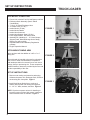
1. Remove outer crating and protective packaging.
ack to blower
housing
utilizing
Unfasten the
power unit, discharge
stack, and hitch
mount swing arm from pallet. Figure 1
¼”) bolts.
2. Install Hitch Mount Swing Arm to receiver of
vehicle. Mount power unit utilizing the supplied
4 – 1/2” X 1” bolts, washers, and nuts. Figure 2
NOTE: Lift points on power unit are for installing or
removing power unit from hitch mount / swing arm
when overhead winch is available. Figure 3
8
(B) Install 7”dia. Metal Hose to discha
stack using metal hose clamp.
FIGURE 3
arm from pallet.
Note:
Lift points on power unit are for installin
STEP 3: Stack
Assembly
power
unit from hitch mount / swing ar
all Hitch Mount Swing Arm to receiver of vehicle.
overhead
is available.
SETwinch
UP INSTRUCTIONS
nt power unit utilizing the supplied
(A) Attach Discharge Stack to blower housing uti
TRUCKLOADER
½” X 1” bolts, washers, and nuts.
8 – (3/8” X 16 X 1 ¼”) bolts.
points on power unit are for installing or removing
STEP 3: Stack Assembly
er unit from3. hitch
mountStack
/ swing
arm
when
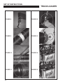
Attach Discharge
to blower
housing
utilizing 8 – (3/8” X 1 1/4”) bolts, 16 flat washers,
head winch is8 split
available.
(A) Attach Discharge Stack to blower housing util
washers and 8 nuts. Figure 4
4. Install 7”dia. Metal Hose to discharge stack using
metal hose clamp. Figure 5
Assembly 5. Attach Boom Arm to Boom Mast utilizing 2 –
FIGURE 4
(3/8”-16 X 1 1/4”) bolts, washers, and nuts.
Figure 6
charge Stack to blower housing utilizing
Install Boom Assembly to receiver on rear of
16 X 1 ¼”)6.bolts.
discharge stack. Figure 7
7.Attach Boom Chain to Eyelet on End of Boom.
Figure 8
8 – (3/8” X 16 X 1 ¼”) bolts.
(B) Install 7”dia. Metal Hose to discharge
stack using metal hose clamp.
STEP 4: Boom Assembly
8.Attach Support Strap to 10” Intake Hose utilizing
1-(3/8”X2”) bolt w/flat washer and nylock nut.
Note: Support Strap Needs to be centered on the
(A)
Intake Hose. Figure 9
Attach Boom Arm to Boom Mast utilizing
2 –FIGURE
(3/8”
X5 1Assembly
¼”) bolts, washer, and nuts.
STEP
4:
Boom
9.Install Handle to Nozzle assembly. Attach Nozzle
Assembly to one end of the Intake Hose utilizing
10” Worm Drive Clamp. Figure 10
(A)
10.Install Intake Hose Connector to opposite end of
Intake Hose utilizing the same size Worm Drive
Clamp. Figure 11
11.Attach Boom Chain to Eyelet on the Support
Band. Figure 12
m Assembly
12.Install intake hose connector to intake cover.
FigureMast
13
om Arm to Boom
utilizing
1 ¼”) bolts, washer, and
nuts.
EYE PROTECTION and GLOVES
Attach Boom Arm to Boom Mast utilizing
2 –A
(3/8” X 1 ¼”) bolts, washer, and nuts.
A
(B) Install Boom Assembly to receiver on
FIGURE
6 discharge stack.
rear of
are REQUIRED. Battery Acid Activation should be
added in a ventilated area.
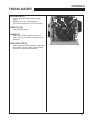
13.Service and Install Battery. Install airflow tube
to battery and to the drain hole in base of power
unit. Install battery to base of power unit and (C) Attach Boom
attach battery bracket, utilizing 2- (#12X3/4”)
End of Boom
self-tap screws Figure 14
14.Attach Red (positive) and Black (negative)
(C)
cables to the designated terminals. Figure 15
15.Service Engine - See engine manufacture’s
manual.
Important Note: Don’t Stand on Unit.
B
Chain to Eyelet on
Attach Boom Chain to Eyelet on
All specifications
End of Boom
FIGURE 7
All specifications a
Warning: Heavy weight. May need
assistance installing.
om Chain to Eyelet on
m
C
9
ilizing the Same Size
Support Band.
om Mast utilizing
(B) Install Boom Assembly to receiver on
washer,SET
and UP
nuts.INSTRUCTIONS rear of discharge stack.
TRUCKLOADER
B
Assembly Instructions, cont.
Assembly Instructions, cont.
Solutions
Solutions
STEPFIGURE
5: Hose
8 Assembly
STEP 5: Hose
Assembly
FIGURE 12
AA: : Attach
Support Strap to 10” Intake hose utilizing
Attach Support Strap to 10” Intake hose utilizing
B: Install Handle to Nozzle assem
B: Install Handle to Nozzle assemb
1-1-(3/8”X2”)
washerand
andnylock.
nylock.
(3/8”X2”) bolt
bolt w/
w/ flat
flat washer
yelet on
C
ons,Connector
cont.
Hose
to Intake Cover Assembly.
remove
the Intake
All specifications
are Cover
subject toDoor
changefrom
withoutIntake
notice. Cover Assembly.
Assembly Instructions, cont.
FIGURE 9
tilizing
.
FIGURE 13
STEP 7: Service and Install Battery - Battery Acid is Not Supplied
Page
|8
Solutions
B: Install Handle to Nozzle assembly.
Safety Note:
PROTECTION
GLOVES are REQUIRED.
18HP
– OpEYE
Manual
Rev 0and
8/8/11
Battery Acid Activation should be added in a ventilated area.
A: Install airflow tube to battery and to
the drain hole in base of power unit.
Assembly Instructions, cont.
A
Note:Support
Support Strap
Strap Needs to
C:C:
Attach
Nozzle
Assembly
Note:
to be
becentered
centeredon
onthe
the
Attach
Nozzle
Assembt
STEP
7:
Service
and
Install
Battery
Battery
Acid
is
Not
Supplied
Intake Hose.
Hose.
the
Intake
Hose
Utilizing
Solutions
Intake
the
Intake
Hose
Utilizin
Drive
Clamp.
Safety Note: EYE PROTECTION and GLOVES are REQUIRED.
Drive Clamp.
Battery Acid Activation should be added in a ventilated area.
FIGURE 10
FIGURE 14
Install airflow tube
battery and to
InstallIntake
Intake Hose
HoseA: Connector
Connector
totoOpposite
D:D:Install
the drain hole in to
baseOpposite
of power unit.
E:E:Attach
Boom
Chain
to to
Eyelet
on oth
Attach
Boom
Chain
Eyelet
Support
Band.
Support
Band.
Endof
ofIntake
Intake Hose
Hose Utilizing
Utilizing the
End
theASame
SameSize
Size
Worm Drive Clamp.
Worm Drive Clamp.
B
All specifications
are subject
to to
cha
notice.
C: Attach Nozzle
Assembly
Onenge
Endwithout
ofInstall battery
to base of power unit and
B:
n the
the Intake Hose Utilizing 10” Worm
Drive Clamp.
FIGURE 11
attach battery bracket, utilizing 2- (#12X¾”)
self-tap screws.
STEP 8:
FIGURE 15
E: Attach Boom Chain to Eyelet on the
Support Band.
C: Attach Red (
cables to the
Page | 9
Service Engine– See engine manufacture’s manual.
18HP – Op Manual Rev
Important Note: Don’t Stand on U
10
STEP 5: Install
B
B: Install battery to base of power unit and
bracket, to
utilizing
2- (#12X¾”)
Intake attach
Hosebattery
Connector
Intake
Cover
Warning: Heavy weight. May need assistan
C
C: Attach Red (positive) and Black (negative)
cables to the designated terminals.
Assembly.
CONTROLS
TRUCKLOADER
KEY SWITCH (A)
Turn clockwise to "START" position to start
engine.
Release key to turn to "RUN" position.
Turn counter-clockwise to "STOP" the engine.
C
A
D
THROTTLE (B)
Controls engine speed.
CHOKE (C)
Move to the "CHOKE" position to apply the
choke. Move to the "RUN" position to remove
the choke.
B
FUEL SHUT OFF (D)
Rotate to shut off the fuel whenever transporting
the machine or during storage. Rotate to allow
fuel to flow to engine during operation.
11
OPERATION
TRUCKLOADER
INTENDED USE
This unit is intended for vacuuming leaves, clippings and other similar sized organic material from the ground
into a truck or trailer. Large sized or long stringy material will tend to clog.
Vacuuming sand, rocks, and hard litter will shorten the life of this machine and may damage the machine or
parts of it.
PRE-OPERATION CHECK LIST
(OPERATOR’S RESPONSIBILITY)
-
-
-
-
-
-
-
-
-
12
Review and follow all safety rules and safety
decal instructions.
Check that all safety decals are installed and in
good condition. Replace if damaged.
Check to make sure all shields and guards are
properly installed and in good condition.
Make sure the discharge chute and hose are
installed.
Check the hose, discharge chute, liners, and
housing for wear. Do not operate if these parts
are worn through. Replace or repair before
operating.
Check that all hardware is properly installed and
secured.
Check to be sure engine is free of dirt and
debris. Pay particular attention to the cooling
fins, governor parts and muffler. Clean air intake
screen. Check air cleaner; service if necessary.
Clean area around the oil fill dipstick. Remove
dipstick and check to be sure oil is in operating
range (between marks on dipstick). Add oil if
necessary but Do Not Overfill. See engine
manual for oil specifications. Install dipstick
assembly firmly until cap bottoms out on tube.
Dipstick assembly must always be secured into
fill tube when engine is running.
Inspect material to be vacuumed and remove
stones, branches or other hard objects that
might damage the machine or cause it to clog.
BEFORE STARTING THE ENGINE
1. Be familiar with the controls, how each functions,
and what each operates.
2. Check engine oil level. Add oil if necessary,
following the engine manufacturer’s
recommendations. Refer to engine manual
included with literature packet.
3. Check the air cleaner for dirty, loose, or
damaged parts. Clean or replace if necessary.
4. Check the air intake and cooling area for dirt or
debris and clean as necessary.
Gasoline is extremely flammable and highly
explosive under certain conditions. BE SURE to
install fuel cap after refueling.
Fill fuel tank with good quality, clean, unleaded
regular gasoline to the level recommended by the
engine manufacturer.
TO CHECK OR ADD FUEL:
-
-
-
-
-
-
Use a funnel to avoid spilling.
Do it outdoors.
Do not smoke.
Stop the engine; allow to cool.
Do not overfill.
Clean up spilled fuel.
STARTING THE ENGINE
1. Check oil level (Daily).
2. Turn fuel shut off valve to OPEN.
3. Put choke control in “CHOKE” position (Briggs
Vanguard only)
4. Move throttle control 1/3 of the way toward high
speed position.
5. Turn key to the START position.
6. Let engine warm up. Slowly adjust CHOKE
toward RUN position.
OPERATION
TRUCKLOADER
OPERATING
This machine has been designed for two methods of
vacuuming debris:
- With the handle of the Intake Nozzle in the
operator’s hands, move the nozzle back and forth
in a sweeping motion over the debris
- Rotate Intake Nozzle to lay sideways on the
ground. By placing the Nozzle in this position,
debris can be raked into the nozzle by an
operator.
While large amounts of debris can be vacuumed
quickly with this machine, caution must be taken to
avoid blocking the airflow into the Nozzle.
STOPPING THE ENGINE
Removing Clogs ( continued)
CAUTION SHOULD BE USED WHEN CLEARING
DEBRIS FROM INSIDE THE HOUSING. GLOVES
SHOULD BE WORN AS SHARP EDGES ON THE
IMPELLER OR IN THE DEBRIS MAY BE PRESENT.
Remove the Hose Assembly from the Inlet Flange
Assembly. With this removed, open the Inlet Flapper
and remove any debris that is clogging the housing.
Remove the Discharge Chute from the Transition
Discharge tube’s flange. With the Chute removed,
inspect the Transition Discharge part of the housing
and remove any debris clogging this area.
When operation is complete or the unit needs to be
checked or a clog needs to be cleared:
1. Move the throttle to SLOW.
2. Turn the key switch to the OFF position.
3. Close fuel valve.
4. Note: Impeller will continue to rotate for several
seconds after engine is stopped.
Reassemble removed parts, reconnect the spark plug
wire and resume operation.
EXCESSIVE VIBRATION
1. Make sure that engine is turned off.
2. Turn fuel valve to the OFF position.
3. Check to insure that the carabiner chain on
nozzle is secured (based on the units mounting
provisions.)
4. After use make sure unit is secured.
5. Remove Intake Hose Assembly
6. Remove Boom Assembly.
Shut off the engine immediately if abnormal/excessive
vibration occurs. Remove spark plug wire. Find
the cause of vibration and repair it. Some possible
causes for excessive vibration are:
- Damaged impeller
- Loose impeller bolt
- Loose impeller key
- Lodged objects
CLOGS
To prevent clogs, do not overfeed, especially with
heavy wet material.
Pay attention to how full the debris receptacle is.
Overfilled debris receptacles cause material to back
up and get tightly packed in the discharge cute.
NEVER TRANSPORT MACHINE WHILE IT IS
RUNNING
SKID MOUNT MACHINE
HITCH MOUNT SWING ARM
1. C
heck to ensure that the swing arm is in the
closed position and the locking bolt is secured
and tight.
2. Ensure the safety chain is secured to the
vehicle.
REMOVING CLOGS
If a decrease in suction is experienced, there may be
a debris blockage in the hose. Often a clogged hose
can be cleared by stretching the hose out straight with
the engine running. If the hose does not clear, you
will need to remove the hose. Before removing the
hose or attempting to clear a clog manually:
- STOP the engine. Turn the key switch to the OFF
position.
- Wait for the impeller to come to a complete stop.
- Disconnect the spark plug wires so impeller
movement cannot accidentally start the engine.
13
MAINTENANCE / STORAGE
DAILY MAINTENANCE
- Inspect the intake hose connector to make sure it
is securely fastened to the intake cover assembly
- Inspect the hose, chute, chute liner, and blower
housing liner for wear. Replace worn parts or
have them repaired.
- Tighten any loose fasteners.
ENGINE OIL
- Check the oil level daily.
- Change after the first day of operation and then
according to the engine manual.
- See the engine manual for oil specifications and
checking procedure.
TRUCKLOADER
ENGINE AIR CLEANER
- Check and clean according to the engine
manuals.
-Little Wonder recommends daily inspection and
cleaning due to the extreme environment of
debris handling.
CLEANING
Keep the area around the muffler and engine
recoil cover /cooling air intake free of debris
accumulation to prevent fires and keep the engine
from overheating. These areas need to be monitored
throughout the work day and may need to be cleaned
several times daily depending on circumstances.
STORAGE
To prevent possible explosion or ignition of vaporized
fuel, do not store equipment with fuel in tank or
carburetor in an enclosure or enclosed area with an
open flame (for example, a furnace or water heater
pilot light.)
Before the equipment is put into storage for any
period exceeding 30 days, the following steps
should be completed.
1. Drain all fuel from the fuel tank and the fuel lines.
Drained fuel may only be stored for 30 days. If
a stabilizer is chosen, follow the manufacturer's
recommendation by adding the correct amount of
additive for the amount of fuel to be stored. Fill
the tank with this clean, fresh gasoline and run the
engine for 2 to 3 minutes to get the stabilized fuel
into the carburetor.
2. Start the engine and run until all the fuel is used
from the carburetor float bowl and the engine
stops.
3. While the engine is still warm, drain the crankcase
oil and replace with the proper weight oil
corresponding to the season the equipment will be
used next.
14
4. Remove the spark plug and squirt a small amount
of engine oil into the cylinder. Reinstall the plugs
and ground spark plug leads- DO NOT connect
the leads to the plugs. Crank the engine two or
three revolutions.
5. Store the unit and all of it's components in a
clean, dry, well ventilated, non-child accessible,
sheltered area that is out of sun light and high
ambient temperatures.
To put the equipment into service after an
extended period of storage.
1. Check for loose parts and tighten if necessary.
2. Fill the fuel tank and then check the engine oil
level. Top off if necessary. See engine manual for
details.
3. Start the engine and check for fuel leaks. Repair
any leaks before operating the unit.
SPECIFICATIONS
TRUCKLOADER
Model
Engine
Displacement
cm3(cu. in)
Starter
Fuel Capacity
Oil Capacity
Vacuum Hose
Discharge
8183-04-01
8184-04-01
18HP Vanguard
18HP Vanguard
479 (29.23)
479 (29.23)
Electric / Pull Start
Electric / Pull Start
1.5 Gal. EPA (Low Perm)
1.5 Gal. EPA (Low Perm)
1.36 – 1.42 Liter
1.36 – 1.42 Liter
10”dia.x 10’
10”dia.x 10’
7 inch
7 inch
Class Requirements
Impeller
Class 3
All Models: 4 Blade 3/8” w/ Steel Taper Locking Hub
Dimensions
Shipped
Skid Mount: 57”L X 46”W X 37”H
Hitch Mount: 57”L X 46”W X 37”H
Dimensions
Assembled
Skid Mount: 40”L X 37”W X 98”H
Hitch Mount: 84”L X 55”W X 112”H
Dry Weight
500 lbs.
620 lbs.
15
PARTS
TRUCKLOADER
11
10
2
8
7
12
9
18
14
15
6
13
4
1
17
16
5
16
3
PARTS
TRUCKLOADER
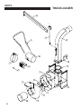
ITEM PART NO.
DESCRIPTION
QTY.
1
MP020035.31
Housing Assembly
1
2
MP020036.31
Dishcharge Stack
1
3
MP020037.10
Intake Cover Assembly
1
4
MP020038.17
Door, Intake Cover
1
5
MP020039.17
Intake Hose Connector
1
6
MP020034
18HP Liner Kit
1
7
MP020040.17
Nozzle Assembly
1
8
MP020041.17
Handle, Pick-Up Tube
1
9
MP020042.17
Strap, 11.25" Intake Hose
1
10
MP020043.17
Boom Mast
1
11
MP020044.17
Boom Arm
1
12
MP020045.32
Battery Hold-Down
1
13
MP020028
Impeller Assembly
1
14
MP020103.32
Exhaust Cover
1
15
MP010050
.25 Sq X 2" Key
1
16
MP020046
Cover Plate, Impeller Hub
1
17
MP010020
Shaft Spacer, 18HP
1
18
MP010067
Gasket, Discharge Chute
1
Optional Accessories:
Hitch Mount:
PN# MPE-020002 (18HP / 14HP – Skid)
Exhaust Stack Extension 24”:
PN# MPE- 020116 (18HP)
17
2 YEAR LIMITED SERVICE AND
WARRANTY POLICY
FOR LITTLE WONDER TRUCKLOADERS
All LITTLE WONDER TRUCKLOADERS are warranted against defects in material and workmanship for a period
of two (2) years from the date of purchase, under the following terms and conditions.
LITTLE WONDER will repair or replace, at its option, any part or parts of the product found to be defective in material or workmanship during the warranty period. Warranty repairs and replacements will be made without charge
for parts or labor. All parts replaced under warranty will be considered as part of the original product, and any
warranty on the replaced parts will expire coincident with the original product warranty. If you think your LITTLE
WONDER TRUCKLOADER is defective in material or workmanship, you must return it to a registered dealer with
a valid sales receipt or to our factory at 1028 Street Rd., Southampton, PA 18966. Transportation charges to ship
your product to us or a registered dealer must be borne by you.
Engines for all gasoline powered products are warranted separately by the engine manufacturer. Therefore, there
are no warranties made, expressed or implied, for engines for gasoline powered products by LITTLE WONDER.
LITTLE WONDER assumes no responsibility in the event that the product was not assembled or used in compliance with any assembly, care, safety or operating instructions contained in the Owner’s Manual or information
accompanying the product. This limited warranty does not cover damages or defects due to normal wear and
tear, lack of reasonable and proper maintenance, failure to follow operating instructions or Owner’s Manual,
misuse, lack of proper storage or accidents, nor does it cover routine maintenance parts and service. This limited
warranty does not cover any defects due to repairs or alterations made to the product made by anyone other than
LITTLE WONDER or its registered dealers.
You must maintain your LITTLE WONDER TRUCKLOADER by following the maintenance procedures described
in the owner’s manual. Such routine maintenance, whether performed by you or a registered dealer, is at your
expense.
LITTLE WONDER MAKES NO EXPRESS OR IMPLIED WARRANTIES REPRESENTATIONS OR PROMISES
EXCEPT THOSE CONTAINED HEREIN. THERE ARE NO OTHER WARRANTIES, INCLUDING WARRANTIES
OF MERCHANTABILITY AND FITNESS FOR A PARTICULAR PURPOSE. ALL WARRANTIES OTHER THAN
THE EXPRESS WARRANTY SET FORTH ABOVE ARE SPECIFICALLY DISCLAIMED. THE DURATION OF
ANY IMPLIED WARRANTY, INCLUDING MERCHANTABILITY AND FITNESS FOR A PARTICULAR PURPOSE,
IS LIMITED TO THE DURATION OF THIS WRITTEN LIMITED WARRANTY. LITTLE WONDER DISCLAIMS
ALL LIABILITY FOR INDIRECT, INCIDENTAL AND/OR CONSEQUENTIAL DAMAGES IN CONNECTION WITH
THE USE OF THE LITTLE WONDER TRUCKLOADER PRODUCTS COVERED BY THIS WARRANTY. SOME
STATES DO NOT ALLOW LIMITATIONS ON HOW LONG AN IMPLIED WARRANTY LASTS AND/OR DO NOT
ALLOW THE EXCLUSION OR LIMITATION OF INCIDENTAL OR CONSEQUENTIAL DAMAGES, SO THAT
ABOVE LIMITATIONS AND EXCLUSIONS MAY NOT APPLY TO YOU. THIS WARRANTY GIVES YOU SPECIFIC LEGAL RIGHTS, AND YOU MAY ALSO HAVE OTHER RIGHTS WHICH VARY FROM STATE TO STATE
LITTLE WONDER®
SCHILLER GROUNDS CARE, INC.
1028 STREET ROAD, P.O. BOX 38
SOUTHAMPTON, PA 18966
PHONE 877-596-6337 • FAX 215-357-8045
www.littlewonder.com
©2012 Schiller Grounds Care, Inc. All Rights Reserved.
18