1
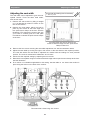
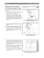
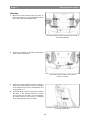
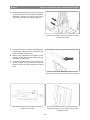
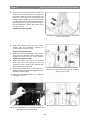
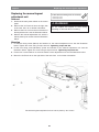
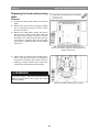
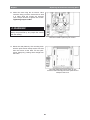
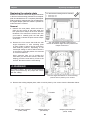
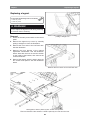
SERVICE MANUAL
US
Corpus 3G
Seat system for electric wheelchair
How to contact Permobil
Head Office of the Permobil group
Produced and published by Permobil AB, Sweden
Version 4, 2014-07
Item No.: 205260-US-0
Contents
Contents
Introduction............................................................................................................. 5
Technical support................................................................................................ 5
Spare parts & accessories.................................................................................. 5
Disposal............................................................................................................... 5
Warranty & servicing........................................................................................... 5
Maintenance........................................................................................................ 5
Product approval................................................................................................. 5
Adjustment.............................................................................................................. 6
Adjusting the seat depth .................................................................................... 6
Adjusting the seat width ................................................................................... 10
Adjusting the backrest height . ......................................................................... 11
Adjusting the armrest height ............................................................................ 12
Adjusting the armrest angle ............................................................................. 13
Adjusting the armrest width ............................................................................. 14
Adjusting the thigh support .............................................................................. 15
Adjusting the trunk support .............................................................................. 15
Repairs.................................................................................................................. 16
Replacing a UniTrack rail ................................................................................. 16
Replacing seat plates . ..................................................................................... 17
Replacing backrest plates ................................................................................ 18
Replacing the armrest height adjustment mechanism...................................... 20
Replacing the manual legrest adjustment unit.................................................. 24
Replacing the manual backrest adjustment unit............................................... 25
Replacing the legrest actuator ......................................................................... 26
Replacing the backrest actuator ...................................................................... 27
Replacing the seat angle mechanism .............................................................. 28
Replacing the fixed seat mounting plate . ........................................................ 32
Replacing the adapter plate ............................................................................. 36
Replacing a legrest........................................................................................... 38
Replacing a legrest strap.................................................................................. 40
Replacing the legrest slide bushings................................................................ 41
Replacing the footplate .................................................................................... 42
Recommended cushions, seat plates and UniTrack rails................................ 43
Cabling overview.................................................................................................. 44
Index...................................................................................................................... 46
4
Introduction
Introduction
The Service Manual is intended for technical personnel who maintain and repair power wheelchairs.
It is important that anyone who performs maintenance and repairs described in this manual reads and
understands the content of this manual so that the work is performed professionally. Always state the
chassis number when contacting Permobil to ensure that the correct information is provided.
Technical Support
In the event of technical problems, you should contact your dealer, or Permobil Inc. USA at 800-736-0925.
Spare parts
Spare parts must be ordered through your dealer.
Warranties
Contact your dealer or Permobil Inc. USA for information about the warranties for this chair.
Maintenance
See the information in the Owner’s Manual.
5
Adjusting the seat depth
Adjustment
Adjustment
For this task the following tools are necessary:
1 Allen key 5 mm
Adjusting the seat depth
The seat depth can be adjusted to suit different
users. There are nine fixed levels, each 25 mm apart.
Adjustment of the seat depth is performed by
mounting the front section of the Seat frame incl.
Leg rest and the rear section of the seat frame
incl. Back rest into desired positions according
to the table on 7 and 8. When the seat depth is
adjusted it may be necessary to replace cushions,
seat plates and UniTrack rails for ones of the
appropriate length. The mounting position for the
seat on the seat lift/fixed seat column may also
need adjusting. See 37.
1. Remove the seat cushion by lifting it straight
up. It is attached by means of Velcro on the
rear of the cushion.
The seat plates are held in place by two
screws at the back edge and two quick-mount
clamps at the front.
2. Remove the seat plates, which are held in
place by two screws at the back edge and
two quick-mount clamps at the front. See the
illustration. First remove the screws, then use
your hand to carefully push the seat plate
from below to release the quick-mount clamps
at the front.
3. Remove the UniTrack rails which are each held
in place by two screws. See the illustration.
The UniTrack rails are fixed in place
with two screws each.
6
Adjusting the seat depth
Adjustment
Adjustment of the front section of the Seat frame (Leg rest position)
4. Remove the five screws marked (L) securing the Seat frames front section, see fig below.
5. Adjust the seat depth by moving the front section of the seat frame to the required position. The rails
with which the seat depth is adjusted are marked with the settings for each potential position. The
scale is marked with “millimeters” on one side and “inches” on the other.
6. Secure it at the required setting by remounting the five screws.
The position of the front part of the Seat frame (Leg rest position) is fixed by five
screws marked with the letter L.
Seat depth
370 mm.
395 mm.
420 mm.
445 mm.
470 mm.
495 mm.
520 mm.
545 mm.
570 mm.
/
/
/
/
/
/
/
/
/
15”
16”
17”
18”
19”
20”
21”
22”
23”
Back rest position
Leg rest position
M300/M400
Other Models
M300/M400
Other Models
N/A
-100 mm. / -4”
N/A
0
-100 mm. / -4”
-75 mm. / -3”
+25 mm. / +1”
0
-75 mm. / -3”
-50 mm. / -2”
+25 mm. / +1”
0
-50 mm. / -2”
-25 mm. / -1”
+25 mm. / +1”
0
-25 mm. / -1”
0
+25 mm. / +1”
0
0
0
+25 mm. / +1” +25 mm. / +1”
0
0
+50 mm. / +2” +50 mm. / +2”
0
0
+75 mm. / +3” +75 mm. / +3”
0
0
+100 mm. / +4” +100 mm. / +4”
7
Adjusting the seat depth
Adjustment
Adjustment of the rear section of the Seat frame (Back rest position).
7. Remove the seven screws marked (B) securing the Seat frames rear section, see fig. below.
8. Adjust the seat depth by moving the rear section of the seat frame to the required position. The rails
with which the seat depth is adjusted are marked with the settings for each potential position. The
scale is marked with “millimeters” on one side and “inches” on the other.
9. Secure it at the required setting by remounting the five screws.
The position of the rear section of the Seat frame (Back rest Position) is fixed by five
screws marked with the letter L.
Seat depth
370 mm.
395 mm.
420 mm.
445 mm.
470 mm.
495 mm.
520 mm.
545 mm.
570 mm.
/
/
/
/
/
/
/
/
/
15”
16”
17”
18”
19”
20”
21”
22”
23”
Back rest position
Leg rest position
M300/M400
Other Models
M300/M400
Other Models
N/A
-100 mm. / -4”
N/A
0
-100 mm. / -4”
-75 mm. / -3”
+25 mm. / +1”
0
-75 mm. / -3”
-50 mm. / -2”
+25 mm. / +1”
0
-50 mm. / -2”
-25 mm. / -1”
+25 mm. / +1”
0
-25 mm. / -1”
0
+25 mm. / +1”
0
0
0
+25 mm. / +1” +25 mm. / +1”
0
0
+50 mm. / +2” +50 mm. / +2”
0
0
+75 mm. / +3” +75 mm. / +3”
0
0
+100 mm. / +4” +100 mm. / +4”
8
Adjusting the seat depth
Adjustment
10. Mount UniTrack rails of a suitable length for the
seat depth setting. See the table on 43. The
rails are each held in place by two screws. See
the illustration. Use a torque wrench to tighten
the screws.
Tightening torque 9.8 Nm.
The UniTrack rails are fixed in place
with two screws each.
11. Mount seat plates of a suitable length for the
seat depth setting. See the table on 43. The
plates are held in place by two screws at the
back edge and two quick-mount clamps at the
front. See the illustration.
12. Fit a cushion of a suitable length/width for
this setting. See the table on 43. Secure the
cushion in place using the Velcro on the back
of the cushion.
The seat plates are held in place by two
screws at the back edge and two quick-mount
clamps at the front.
m WARNING!
The seat's mounting position on the seat lift/fixed seat column may need to be changed following
adjustment of seat depth. Failure to do this correctly may impair the driving properties of the
wheelchair, leading to an increased risk of personal injury and damage to property, including
damage to the wheelchair. See 37 for further information.
9
Adjusting the seat width
Adjustment
Adjusting the seat width
For this task the following tools are necessary:
1 Allen key 5 mm
The seat width can be adjusted to give the user
optimal comfort. There are three fixed levels,
each 25 mm apart.
1. Remove the seat cushion by lifting it straight
up. It is attached by means of Velcro on the
rear of the cushion.
2. Remove the seat plates, which are held in
place by two screws at the back edge and
two quick-mount clamps at the front. See the
illustration. First remove the screws, then use
your hand to carefully push the seat plate
from below to release the quick-mount clamps
at the front.
The seat plates are held in place by two
screws at the back edge and two quick-mount
clamps at the front.
3. Remove the four screws securing the seat width adjustment unit. See the illustration below.
4. Adjust the seat width by moving the right or left section of the seat frame to the required position.
The rails with which the seat width is adjusted are marked with the settings for each potential
position. The scale is marked with "millimeters" and "inches".
5. Secure it at the required setting by replacing the four screws.
7. Remount the seat plates using two screws at the back edge and two quick-mount clamps at the front.
See the illustration.
8. Fit a cushion of a suitable length/width for this setting. See the table on 43. Secure the cushion in
place using the Velcro on the back of the cushion.
The seat width is fixed using four screws.
10
Adjusting the backrest height
Adjustment
Adjusting the backrest height
For this task the following tools are necessary:
1 Allen key 3 mm
The backrest height can be adjusted to give the
user optimal comfort. Adjustment is possible
by moving the locking mechanism on the upper
section of the backrest between six fixed stages
25 mm apart.
1. Remove the backrest cushion by pulling it
straight forwards. It is attached by means of
Velcro on the rear of the cushion.
2. For access to the locking mechanism, set the
backrest angle to its most upright position.
Remove the upper section of the backrest
by carefully opening the locking mechanism
catch outwards while also pulling the upper
section of the backrest straight up. See the
illustration.
The upper section of the backrest is secured
with a locking mechanism.
3. Remove the two screws holding the backrest
locking mechanism in place. See the
illustration.
4. Adjust the height of the backrest by sliding
the upper section upwards/downwards to
the required position. The upper backrest
plate is marked with the settings for each
potential position. The scale is marked with
"millimeters" and "inches".
The locking mechanism is held
in place by two screws.
5. Lift up the upper section of the backrest
enough that the locking mechanism can be
mounted with its top edge in line with the
required height on the backrest scale. See
the illustration. Mount the locking mechanism
using the two screws.
6. Slide the upper section of the backrest
down until secured in position by the locking
mechanism. See the illustration above.
7. Fit a cushion of a suitable height/width for
this setting. See the table on 43. Secure the
cushion in place using the Velcro on the back
of the cushion.
The backrest locking mechanism mounted for
backrest height 645 mm (26 inches).
11
11
Adjusting the armrests
Adjustment
Adjusting the armrest height
For this task the following tools are necessary:
1 Allen key 5 mm
The height of the armrest can be adjusted to
provide the user with optimal comfort.
1. Undo the four screws holding the armrest at its current height. See the illustration below.
m WARNING!
Do not subject the armrests to load when adjusting them. Risk of crushing.
2. Adjust to the required position using the adjustment screw on the rear of the backrest. See the
illustration below.
3. Secure the armrest at the preferred height by tightening the four screws on the rear of the backrest.
See the illustration below.
The armrest height is fixed using four screws. To perform this height adjustment, use the adjustment
screw in the center of the backrest.
12
12
Adjusting the thigh support and trunk support
Adjustment
Adjusting the armrest angle
The angle of the armrest can be easily adjusted
to provide the user with optimal comfort.
1. Adjust the armrest angle by turning the
adjustment bars. See the illustration.
m WARNING!
Do not subject the armrests to load when
adjusting them. Risk of crushing.
Adjust the armrest angle by turning the
adjustment bars
Individual adjustment of armrest height/angle
m WARNING!
For this task the following tools are necessary:
1 Allen key 5 mm
Do not subject the armrests to load when
adjusting them. Risk of crushing.
This type of adjustment is only performed in
special cases. It may have negative effects
on the movement of the armrest when raising/
lowering the backrest.
The height/angle of the armrest is normally adjusted as described on s 32-33. If specifically required, the
armrests can be adjusted individually for users who want the left and right armrest at different heights
and/or angles. This adjustment is only performed in special cases. It may have negative effects on the
movement of the armrest when raising/lowering the backrest.
1. Adjust the armrest height by turning the adjustment bars (C). See the illustration.
2. The angle of the armrest is secured using a screw (B). Move the screw from a fixed position (A) to a
flexible position (B). See the illustration below.
3. Adjust the armrest to the required angle and secure by tightening the screw (B). See the illustration below.
Individual adjustment of the armrest height and angle
13
13
Adjusting the armrests
Adjustment
Adjusting the armrest width
For this task the following tools are necessary:
1 Allen key 5 mm
The distance between the armrests can be
adjusted to give the user optimal comfort.
1. Loosen the screw for armrest width adjustment
approximately 3 turns. See the illustration.
2. Push in/pull out the armrest shaft to the
desired position.
3. Secure it at the required setting by retightening
the screw.
The armrest width is fixed using one screw.
Turn the adjustment bar bracket
With the armrests set both wide and low, the
adjustment bar for the left armrest angle can touch
the rear actuator bracket for the backrest angle.
If this is the case, turn the adjustment bar bracket.
For this task the following tools are necessary:
1 Combination wrench 10 mm.
1. Remove the lower bracket of the adjustment bar, which is secured with a screw, washer and nut. See the
illustration (1).
2. Turn the bracket 180° so the adjustment bar is closer to the center of the seat. See the illustration (2).
3. Refit the lower bracket of the adjustment bar in its new position using the screw, washer and nut.
See the illustration (3).
Turn the bracket 180° so the adjustment bar is closer to the center of the seat.
14
14
Adjustment
Adjusting the thigh support and trunk support
Adjusting the thigh support
The position of the thigh support can be adjusted
forwards or backwards to give the user optimal
comfort. Slide the thigh support forwards or
backwards to the desired position.
The position of the thigh support can be adjusted
Adjusting the trunk support height
For this task the following tools are necessary:
1 Allen key 5 mm
The height of the trunk support can be adjusted
to give the user optimal comfort.
1. Loosen the screw for trunk support height
adjustment approximately 2 turns. See the
illustration.
2. Slide the trunk support up/down to the desired
position.
3. Secure it at the required setting by retightening
the screw.
The trunk support height is fixed using one screw.
15
15
Replacing a UniTrack rail
Repairs
Repairs
For this task the following tools are necessary:
1 Allen key 5 mm
Replacing a UniTrack rail
UniTrack rails are available in five different lengths
that are used depending on the seat depth
selected. See the table on 43.
Removal
1. Remove the two screws that hold the rail in
place. See the illustration.
Mounting
1. Mount the UniTrack rail using two screws.
See the illustration. Use a torque wrench to
tighten the screws.
Tightening torque 9.8 Nm.
The UniTrack rail is held in place by two screws.
16
Replacing seat plates
Repairs
Replacing seat plates
For this task the following tools are necessary:
Seat plates are available in five different lengths
that are used depending on the seat depth
selected. See the table on 43.
1 Allen key 3 mm
Removal
1. Remove the seat cushion by lifting it straight
up. It is attached by means of Velcro on the
rear of the cushion.
2. Remove the seat plates, which are held in
place by two screws at the back edge and
two quick-mount clamps at the front. See the
illustration. First remove the screws, then use
your hand to carefully push the seat plate
from below to release the quick-mount clamps
at the front.
The seat plates are held in place by two
screws at the back edge and two quick-mount
clamps at the front.
Mounting
1. Mount the seat plates by first mounting them
with the quick-mount clamps at the front and
then the screws at the back. Fit the quickmount clamps by pushing them straight into
the holes.
2. Fit the seat cushion by pressing it against the
seat plate in the desired position to ensure
good contact for the Velcro on its underside.
17
Replacing backrest plates
Repairs
Replacing backrest plates
Backrest plates are available in three different
widths to fit most users. If you change the size of
the backrest plates you will also have to change
the cushion to one that is a suitable size. See the
table on 43.
Removal
1. Remove the backrest cushion by pulling it
straight forwards. It is attached by means of
Velcro on the rear of the cushion.
2. Remove the backrest upper plate. For
access to the locking mechanism, set the
backrest angle to its most upright position.
Remove the upper section of the backrest
by carefully opening the locking mechanism
catch outwards while also pulling the upper
section of the backrest straight up. See the
illustration.
The upper section of the backrest is secured
with a locking mechanism.
3. Remove the knob securing the position of the
lower backrest plate. See the illustration.
The lower backrest plate is secured
by means of a knob
4. Remove the backrest by pulling the backrest
plate straight up so it can be removed from
the four locking devices. See the illustration.
The lower backrest plate is secured by
means of four locking devices
18
Replacing backrest plates
Repairs
Mounting
1. Mount the lower backrest plate by lining up
the four "keyholes" on the locking devices and
then sliding the plate straight down.
The lower backrest plate is secured by means of
four locking devices
2. Secure the position of the plate by fitting the
knob. See the illustration.
The lower backrest plate is secured by
means of a knob
3. Mount the upper backrest plate by sliding it
down into the lower plate's grooves. The height
of the backrest may need to be adjusted. This
is described on 11.
4. Fit the backrest cushion by pressing it against
the plate in the desired position to ensure
good contact for the Velcro on its underside.
The lower section of the cushion is fastened
to the seat plate by means of Velcro.
The upper section of the backrest is secured with
a locking mechanism.
19
Repairs
Replacing the armrest height adjustment mechanism
Replacing the armrest height adjustment mechanism
For this task the following tools are necessary:
Removal
1 Allen key 3 mm
1 Allen key 5 mm
1. Remove the backrest plates. For a detailed
description, see 18.
2. Loosen the two screws holding the plastic
cover to the back of the backrest. Twist the
plastic cover downwards. See the illustration.
The plastic cover is fixed using two screws.
3. Remove the BUS contacts from the contact
block and divide the cabling for the ICS
switchbox at the contacts on the cabling.
1. The contact on the ICS switchbox cabling is
above the contact block. 2. The BUS contacts are
mounted on the contact block.
4. Remove the four screws that hold the armrests
in place. See the illustration. Then carefully
move the armrests downwards or backwards.
5. Remove the joint for the backrest slide
function, which is held in place by one screw.
See the illustration.
The armrests are held in place by four screws.
The joint for the backrest slide function is held in
place by one screw
20
Repairs
Replacing the armrest height adjustment mechanism
6. Remove the backrest profile, which is secured
using two screws on the left and right. See the
illustration. Remove by undoing the screws
and pulling the backrest profile straight up.
The backrest profile is secured using two screws
on the left and right
7. Loosen the screws on the left and right side of
the backrest profile and then remove its end
cover by sliding it straight out.
8. Remove the adjustment bar brackets, which
are each held in place by two screws. See the
illustration at bottom left.
9. Screw the adjustment bar down far enough to
be able to prise it up out of the groove on the
backrest profile. See the illustration at bottom
right.
The end cover of the backrest profile is secured
using one screw on the left side and one on the right
The adjustment bar brackets are each held in
place by two screws
Screw the adjustment bar down far enough to
be able to prise it up out of the groove on the
backrest profile
21
Repairs
Replacing the armrest height adjustment mechanism
Mounting
1. Push the threaded rod into the backrest profile and at the same time screw on the driver (1). See the
illustration below.
2. Apply threadlocker (Loctite 2701) to the ends of the threaded rod and fit the two end pieces (2 & 3)
onto the threaded rod. See the illustration below.
Loctite 2701
3. Mount the adjustment bar brackets, which are
each held in place by two screws. See the
illustration.
The adjustment bar brackets are each held in
place by two screws
4. Remount the end cover of the backrest profile
by pushing it straight into the end of the profile.
Secure the cover by tightening the screws on
the left and right. See the illustration.
The end cover of the backrest profile is
secured using one screw on the left side
and one on the right
22
Repairs
Replacing the armrest height adjustment mechanism
5. Remount the backrest profile by fitting the
bracket into the profile groove on the left and
right sides. Slide the profile downwards until
the stop on the bracket is touching the end
of the backrest profile on both the left side
and the right. Secure the backrest profile by
tightening the two screws on the left and right.
See the illustration. Tighten the screws using
a torque wrench.
Tightening torque 9.8 Nm.
The backrest profile is secured using two screws
on the left and right
6. Mount the armrests using the four screws
screws. See the illustration. Tighten the
screws using a torque wrench.
Tightening torque 9.8 Nm.
7. Mount the joint for the backrest slide function
using the screw supplied. See the illustration.
Tighten the screw using a torque wrench.
Tightening torque 9.8 Nm.
8. Mount the BUS contacts on the contact
block and mount the cabling for the ICS
switchbox at the contact on the cabling. See
the illustration at bottom left.
9. Remount the plastic cover on the back of the
backrest using the two screws supplied. See the
illustration at bottom right.
The armrests are held in place by four screws.
The joint for the backrest slide function is held in
place by one screw
1. The contact on the ICS switchbox cabling is
above the contact block. 2. The BUS contacts are
mounted on the contact block.
The plastic cover is attached using two screws
10. Remount the backrest plates. For a detailed
description, see 19.
23
Replacing the manual legrest adjustment
Repairs
Replacing the manual legrest
adjustment unit
For this task the following tools are necessary:
1 Allen key 5 mm
1 Allen key 8 mm
Removal
1. Switch off the main power switch on the control
panel.
m WARNING!
2. Remove the UniTrack rail from the right side
of the seat. See 16 for further information.
Do not subject the legrest to load during
mounting or removal. Risk of crushing.
3. Remove the lock nut from the front bracket of
the adjustment unit. See the illustration below.
4. Remove the manual adjustment unit, which is
held in place by two screws. See the illustration
below.
Mounting
1. Fit the rear fixing screw (M6x12) and washer for the manual adjustment unit. See the illustration
below. Tighten the screw using a torque wrench. Tightening torque 9.8 Nm.
2. Fit the front fixing screw (M10x60), spacer and washer for the manual adjustment unit. See the
illustration below. Tighten the screw using a torque wrench. Tightening torque 35 Nm.
3. Fit the lock nut and washer on the front bracket of the adjustment unit. See the illustration below.
4. Mount the UniTrack rail on the right side of the seat. See 16 for further information.
The manual legrest adjustment unit is held in place by two screws
24
24
Replacing the manual backrest adjustment
Repairs
Replacing the manual backrest
adjustment unit
For this task the following tools are necessary:
1 Allen key 5 mm
1 Allen key 8 mm
Removal
1. Switch off the main power switch on the control
panel.
m WARNING!
2. Remove the UniTrack rail from the left side of
the seat. See 16 for further information.
Do not subject the backrest to load during
mounting or removal. Risk of crushing.
3. Remove the lock nut from the rear bracket of
the adjustment unit. See the illustration below.
4. Hold the backrest in a steady grip as you
remove the manual adjustment unit. The
adjustment unit is held in place by two screws.
See the illustration below. Once the first
screw has been removed the backrest can be
angled forward to rest on the seat cushion.
Mounting
1. Mount the front fixing screw (M6x12) and washer for the manual adjustment unit. See the illustration
below. Tighten the screw using a torque wrench. Tightening torque 9.8 Nm.
2. Fit the rear fixing screw (M10x60), spacer, washers and nut for the manual adjustment unit. See the
illustration below. Tighten the screw using a torque wrench. Tightening torque 35 Nm.
3. Mount the UniTrack rail on the left side of the seat. See 16 for further information.
The manual backrest adjustment unit is held in place by two screws
25
25
Replacing the legrest actuator
Repairs
Replacing the legrest actuator
For this task the following tools are necessary:
Removal
1 Allen key 5 mm
1 Allen key 8 mm
2. Remove the UniTrack rail from the right side
of the seat. See 16 for further information.
m WARNING!
1. Switch off the main power switch on the control
panel.
3. Remove the actuator contact from the contact
block above the actuator. See the illustration.
Remove the contact by pulling it straight
out. Loosen the actuator cabling from its
fixing points. Remember how the cabling
is positioned; this helps when you come to
re-attach it.
Do not subject the legrest to load during mounting
or removal. Risk of crushing.
4. Remove the lock nut from the front bracket of
the actuator. See the illustration below.
5. Remove the actuator, which is held in place
by two screws. See the illustration below.
Mounting
1. Fit the rear fixing screw (M6x12) and washer
for the actuator. See the illustration below.
Tighten the screw using a torque wrench.
Tightening torque 9.8 Nm.
2. Fit the front fixing screw (M10x60), spacer and
washer for the actuator. See the illustration
below. Tighten the screw using a torque
wrench. Tightening torque 35 Nm.
The actuator cabling is connected to the contact
block on the right side of the seat
3. Fit the lock nut and washer on the front bracket of the actuator. See the illustration below.
4. Secure the cabling for the actuator in its fixing points. Consider the arrangement of the cables
carefully and make sure there is no risk of them getting trapped or otherwise damaged.
Connect the actuator contact to the contact block on the right side of the seat. See the illustration
above. Fit the contact by pushing it straight in at any point.
5. Mount the UniTrack rail on the right side of the seat. See page 16 for further information.
The legrest actuator is held in place by two screws
26
26
Replacing the backrest actuator
Repairs
Replacing the backrest actuator
For this task the following tools are necessary:
1 Allen key 5 mm
1 Allen key 8 mm
Removal
1. Switch off the main power switch on the control
panel.
m WARNING!
2. Remove the UniTrack rail from both sides of
the seat. See 16 for further information.
Do not subject the legrest to load during mounting
or removal. Risk of crushing.
3. Remove the seat plates. See 17 for further
information.
4. Remove the actuator contact from the contact
block on the right side of the seat. See the
illustration. Remove the contact by pulling it
straight out. Loosen the actuator cabling from
its fixing points. Remember how the cabling
is positioned; this helps when you come to
re-attach it.
5. Remove the lock nut from the rear bracket of
the actuator. See the illustration below.
6. Hold the backrest in a steady grip as you
remove the actuator. It is held in place by two
screws. See the illustration below. Once the
first screw has been removed the backrest
can be angled forward to rest on the seat
cushion.
Mounting
The actuator cabling is connected to the contact
1. Fit the front fixing screw (M6x12) and washer
block on the right side of the seat
for the actuator. Tighten the screw using a
torque wrench. Tightening torque 9.8 Nm.
2. Fit the rear fixing screw (M10x60), spacer, washerand nut for the actuator. Tighten the screw using
a torque wrench. Tightening torque 35 Nm.
4. Secure the cabling for the actuator in its fixing points. Consider the arrangement of the cables
carefully and make sure there is no risk of them getting trapped or otherwise damaged.
Connect the actuator contact to the contact block on the right side of the seat. See the illustration
above. Fit the contact by pushing it straight in at any point.
5. Mount the UniTrack rail on both sides of the seat. See page 16 for further information.
The backrest actuator is held in place by two screws
27
Replacing the seat angle mechanism
Repairs
Replacing the seat angle
mechanism
For this task the following tools are necessary:
1 Allen key 5 mm
1 Allen key 8 mm
Removal
1. Switch off the main power switch on the control
panel.
2. Remove the seat cushion by lifting it straight
up. It is attached by means of Velcro on the
rear of the cushion.
3. Remove the seat plates, which are held in
place by two screws at the back edge and
two quick-mount clamps at the front. See the
illustration. First remove the screws, then use
your hand to carefully push the seat plate
from below to release the quick-mount clamps
at the front.
The seat plates are held in place by two
screws at the back edge and two quick-mount
clamps at the front.
4. Divide the cabling for the seat angle
mechanism at the contact on the cabling. The
contact is at the front right corner of the seat
angle mechanism, next to the other cabling.
See the illustration.
The connector is on the cabling at the front
right corner of the seat angle mechanism, next
to the rest of the cabling
5. Remove the six screws that hold the seat in
place. Have someone help you by holding the
seat while you remove the screws, and then
helping you lift the seat and lay it next to the
chassis. Be careful with the seat cabling.
m WARNING!
The seat is heavy. This work should therefore
always be performed by two people. Be careful
with the cabling.
The seat is held in place by six screws.
28
Replacing the seat angle mechanism
Repairs
6. Remove the four screws that hold the seat angle mechanism in place. See the illustration below.
The seat angle mechanism can be mounted in three different positions, depending on the chassis
the seat is mounted on and the depth of the seat. Note the position the seat angle mechanism is
mounted in for future reference.
Lift the seat angle mechanism off the seat lift/seat column.
Position 1
Position 2
Position 3
The seat angle mechanism is held in place by four screws
29
Replacing the seat angle mechanism
Repairs
Mounting
1. Mount the seat angle mechanism using the four screws. See the illustration. It can be mounted in
three different positions, depending on which chassis it is being mounted on and the depth of the
seat. See the table below. Use a torque wrench to tighten the screws. Tightening torque 24 Nm.
Position 1
Position 2
Position 3
The seat angle mechanism is held in place by four screws
Seat depth
370 mm./15”
395 mm./16”
420 mm./17”
445 mm./18”
470 mm./19”
495 mm./20”
520 mm./21”
545 mm./22”
570 mm./23”
Mounting position
C350 M300 M400 C400
C300
C300S
C500
C500S
1
2
1
1
1
1
1
3
1
2
1
1
1
1
1
3
1
2
1
1
1
1
1
3
1
2
1
1
1
1
1
3
1
2
1
1
1
1
1
3
1
2
1
1
1
1
1
3
2
3
1
1
1
2
2
3
3
3
2
2
2
3
3
3
3
3
3
3
3
3
3
3
The mounting position for the seat angle mechanism depends on the chassis model and the seat depth
setting. The table shows mounting positions for standard model wheelchairs; accessories such as
height-adjustable footplates or a respirator shelf may affect the mounting position. Contact Permobil in
case of doubt.
30
Replacing the seat angle mechanism
Repairs
2. Mount the seat using the six screws. Have
someone help you lift the seat and then hold
it in place while the screws are inserted.
Use a torque wrench to tighten the screws.
Tightening torque 9.8 Nm.
m WARNING!
The seat is heavy. This work should therefore
always be performed by two people. Be careful
with the cabling.
The seat is held in place by six screws.
3. Connect the cabling for the seat angle
mechanism to the wheelchair's ICS Master
Module. If the cabling for the ICS Master
Module is already there, connect it to the
contact that is at the front right corner of the
seat angle mechanism, next to the other
cabling. See the illustration.
When mounting new cabling for the ICS
Master Module, mount it together with the rest
of the cabling running down to the wheelchair
chassis and there connect it to the ICS
Master Module. For further information on the
ICS Master Module, see the chassis service
manual.
The connector is on the cabling at the front right
corner of the seat angle mechanism, next to the
rest of the cabling
4. Mount the seat plates by first mounting them
with the quick-mount clamps at the front and
then the screws at the back. Fit the quickmount clamps by pushing them straight into
the holes.
The seat plates are held in place by two
screws at the back edge and two quick-mount
clamps at the front.
31
Replacing the fixed seat mounting plate
Repairs
Replacing the fixed seat mounting
plate
For this task the following tools are necessary:
1 Allen key 5 mm
1 Allen key 8 mm
Removal
1. Switch off the main power switch on the control
panel.
2. Remove the seat cushion by lifting it straight
up. It is attached by means of Velcro on the
rear of the cushion.
3. Remove the seat plates, which are held in
place by two screws at the back edge and
two quick-mount clamps at the front. See the
illustration. First remove the screws, then use
your hand to carefully push the seat plate
from below to release the quick-mount clamps
at the front.
The seat plates are held in place by two
screws at the back edge and two quick-mount
clamps at the front.
4. Remove the six screws that hold the seat in
place. Have someone help you by holding the
seat while you remove the screws, and then
helping you lift the seat and lay it next to the
chassis. Be careful with the seat cabling.
m WARNING!
The seat is heavy. This work should therefore
always be performed by two people. Be careful
with the cabling.
The seat is held in place by six screws.
32
Replacing the fixed seat mounting plate
Repairs
5. Remove the four screws that hold the seat mounting plate in place. See the illustration below. The
seat mounting plate can be mounted in three different positions, depending on the chassis the seat
is mounted on and the depth of the seat. Note the position the seat mounting plate is mounted in for
future reference.
Lift the seat mounting plate off the seat lift/seat column.
Position 1
Position 2
Position 3
The seat mounting plate is held in place by four screws
33
Replacing the fixed seat mounting plate
Repairs
Mounting
1. Mount the seat mounting plate using the four screws. See the illustration. It can be mounted in three
different positions, depending on which chassis it is being mounted on and the depth of the seat.
See the table below. Use a torque wrench to tighten the screws. Tightening torque 24 Nm.
Position 1
Position 2
Position 3
The seat mounting plate is held in place by four screws
Seat depth
370 mm./15”
395 mm./16”
420 mm./17”
445 mm./18”
470 mm./19”
495 mm./20”
520 mm./21”
545 mm./22”
570 mm./23”
Mounting position
C350 M300 M400 C400
C300
C300S
C500
C500S
1
2
1
1
1
1
1
3
1
2
1
1
1
1
1
3
1
2
1
1
1
1
1
3
1
2
1
1
1
1
1
3
1
2
1
1
1
1
1
3
1
2
1
1
1
1
1
3
2
3
1
1
1
2
2
3
3
3
2
2
2
3
3
3
3
3
3
3
3
3
3
3
The mounting position for the seat mounting plate depends on the chassis model and the seat depth
setting. The table shows mounting positions for standard model wheelchairs; accessories such as
height-adjustable footplates or a respirator shelf may affect the mounting position. Contact Permobil in
case of doubt.
34
Replacing the fixed seat mounting plate
Repairs
2. Mount the seat using the six screws. Have
someone help you lift the seat and then hold
it in place while the screws are inserted.
Use a torque wrench to tighten the screws.
Tightening torque 9.8 Nm.
m WARNING!
The seat is heavy. This work should therefore
always be performed by two people. Be careful
with the cabling.
The seat is held in place by six screws.
3. Mount the seat plates by first mounting them
with the quick-mount clamps at the front and
then the screws at the back. Fit the quickmount clamps by pushing them straight into
the holes.
The seat plates are held in place by two
screws at the back edge and two quick-mount
clamps at the front.
35
Replacing the adapter plate
Repairs
Replacing the adapter plate
For this task the following tools are necessary:
Between the seat lift and the seat angle mechanism
or the fixed seat mounting plate there is an adapter
plate. As standard there is a completely flat adapter
plate mounted. If preferred this can be replaced by
an angled adapter plate that makes it possible to
incline the seat 5° forward.
1 Allen key 5 mm
1 Allen key 8 mm
Removal
1. Remove the seat plates, which are held in
place by two screws at the back edge and
two quick-mount clamps at the front. See the
illustration. First remove the screws, then use
your hand to carefully push the seat plate
from below to release the quick-mount clamps
at the front.
The seat plates are held in place by two
screws at the back edge and two quick-mount
clamps at the front.
2. Remove the four screws that hold the seat
angle mechanism or seat mounting plate
in place. Either of these can be mounted in
three different positions, depending on the
seat depth setting as well as which chassis it
is mounted on. Note the position it is mounted
in for future reference.
Have someone help you by holding the
seat while you remove the screws, and then
helping you lift the seat and lay it next to the
chassis. Be careful with the seat cabling.
m WARNING!
The seat is heavy. This work should therefore
always be performed by two people. Be careful
with the cabling.
The seat angle mechanism or seat mounting
plate is held in place by four screws
3. Remove the existing adapter plate, which is held in place by four screws. See the illustration below.
Forwards
Adapter plate standard
(C400, C500)
Forwards
Adapter plate -5°
(All chassis)
36
Adapter plate standard
(C300, C350)
Replacing the adapter plate
Repairs
Mounting
1. Mount the preferred adapter plate using the
four screws supplied. See the illustration on
the previous . Make sure you have the plate
turned the right way when mounting it. Use a
torque wrench to tighten the screws.
Adapter plate standard
Tightening torque: 24 Nm.
Adapter plate -5°
Tightening torque: 33 Nm.
2. Mount the seat including seat angle
mechanism/seat mounting plate using the four
screws. It can be mounted in three different
positions, depending on the seat depth setting
as well as which chassis it is mounted on. See
the table below. Have someone help you by
holding on to the seat while you fit the screws.
Use a torque wrench to tighten the screws.
The seat angle mechanism or seat mounting
plate is held in place by four screws
Tightening torque 24 Nm.
3. Mount the seat plates by first mounting them
with the quick-mount clamps at the front and
then the screws at the back. Fit the quickmount clamps by pushing them straight into
the holes.
m WARNING!
The seat is heavy. This work should therefore
always be performed by two people. Be careful
with the cabling.
The seat plates are held in place by two
screws at the back edge and two quick-mount
clamps at the front.
Seat depth
370 mm./15”
395 mm./16”
420 mm./17”
445 mm./18”
470 mm./19”
495 mm./20”
520 mm./21”
545 mm./22”
570 mm./23”
Mounting position
C350 M300 M400 C400
C300
C300S
C500
C500S
1
2
1
1
1
1
1
3
1
2
1
1
1
1
1
3
1
2
1
1
1
1
1
3
1
2
1
1
1
1
1
3
1
2
1
1
1
1
1
3
1
2
1
1
1
1
1
3
2
3
1
1
1
2
2
3
3
3
2
2
2
3
3
3
3
3
3
3
3
3
3
3
The mounting position for the seat mounting plate/seat angle mechanism depends on the chassis
model and the seat depth setting. The table shows mounting positions for standard model wheelchairs;
accessories such as height-adjustable footplates or a respirator shelf may affect the mounting position.
Contact Permobil in case of doubt.
37
Replacing a legrest
Repairs
Replacing a legrest
For this task the following tools are necessary:
1 Allen key 5 mm
1 Allen key 8 mm
m WARNING!
Do not subject the legrest to load during mounting
or removal. Risk of crushing.
Remove the legrest's top cover by carefully
pulling it straight out
Removal
1. Switch off the main power switch on the control
panel.
2. Remove the legrest's top cover by carefully
pulling it straight out. See the illustration.
3. Remove the front ends of the UniTrack rails.
See the illustration.
4. Remove the front bracket of the manual
adjustment unit/actuator. See the illustration
below. Start with the lock nut and the washer
on the inside of the bracket, then remove the
screw and washer.
5. Remove the legrest, which is held in place by
two screws and spacers. See the illustration
below.
Remove the front ends of the UniTrack rails
The legrest is held in place by two screws and spacers.
The front bracket of the actuator is held in place by a screw and lock nut.
38
Replacing a legrest
Repairs
Mounting
1. Mount the legrest using the two screws and
spacers. See the illustration on the previous
. Use a torque wrench to tighten the screws.
Tightening torque 24 Nm.
2. Mount the front bracket of the manual
adjustment unit/actuator. See the illustration on
the previous . Start with the screw and washer.
Tighten the screw using a torque wrench.
Tightening torque 47 Nm.
Then fit the lock nut and washer on the inside
of the bracket.
Remove the front ends of the UniTrack rails
3. Mount the front ends of the UniTrack rails.
See the illustration.
4. Mount the legrest's top cover by carefully
pressing its bracket into place on the legrest's
fixing screws/spacers. See the illustration.
Mount the legrest's top cover by carefully
pressing its bracket into place on the legrest's
fixing screws/spacers
39
39
Replacing a legrest strap
Repairs
Replacing a legrest strap
For this task the following tools are necessary:
1 Allen key 3 mm
1 Steel ruler
m WARNING!
Do not subject the legrest to load during
mounting or removal. Risk of crushing.
Lift up the legrest's top cover
Removal
1. Switch off the main power switch on the control
panel.
2. Lift up the legrest's top cover. See the illustration.
3. Remove one end of the legrest strap by
carefully raising the lower section of the
legrest slightly and at the same time removing
the two screws on the front of the legrest.
Then pull the mounting plate out of the loop
of the strap.
Once the strap is loosened the lower section
of the legrest will become loose and can be
carefully placed on the floor.
4. Remove the two screws holding the strap
bracket on the back of the legrest in place.
See the illustration.
5. Pull the strap out of the legrest mechanism.
Mounting
1. Pull the strap through the bracket on the back
of the legrest. Measure to make sure that
the strap extends 85 mm under the bracket.
Secure the strap by tightening the two screws
on the bracket. See the illustration.
2. Slide the lower section of the legrest up and
pull the strap through the legrest mechanism.
See the illustration.
3. Place the mounting plate in the loop of the strap
and then mount this on the front of the legrest
using the two screws. See the illustration.
Strap mounting on the legrest
40
Replacing the legrest slide bushings
Repairs
Replacing the legrest
slide bushings
For this task the following tools are necessary:
1 Allen key 3 mm
m WARNING!
Do not subject the legrest to load during
mounting or removal. Risk of crushing.
The slide bushing in the upper section of the
legrest is attached using two screws.
Removal
1. Set the angle of the legrest to its outermost
position.
2. Switch off the main power switch on the control
panel.
3. Remove one end of the legrest strap by
carefully raising the lower section of the
legrest slightly and at the same time removing
the two screws on the front of the legrest. Pull
the mounting plate out of the loop of the strap.
See the illustration below.
Once the strap is loosened the lower section
of the legrest will become loose and can be
carefully pulled downwards/forwards until the
lower section of the legrest is completely
loose.
4. Remove the slide bushing in the upper section
of the legrest, which is attached using two
screws. See the illustration above.
Slide bushing in the lower section of the legrest
5. Remove the slide bushing in the lower section
of the legrest, and at the same time use a
suitable tool to press in the locking tabs on
the bushing, located in the hole immediately
below the top edge of the legrest. See the
illustration.
Mounting
1. Fit the slide bushing in the lower section of the
legrest, making sure the locking tabs on the
bushing are securely fixed in the hole in the
legrest. See the illustration.
2. Fit the slide bushing in the upper section of
the legrest using the two screws. See the
illustration above.
3. Slide the upper and lower sections of the
legrest together, and pull the legrest strap
through the legrest mechanism. See the
illustration.
4. Place the mounting plate in the loop of the strap
and then mount this on the front of the legrest
using the two screws. See the illustration.
Strap mounting on the legrest
41
Replacing the footplate
Repairs
Replacing the footplate
For this task the following tools are necessary:
Removal
1 Allen key 5 mm
2. Remove the screw holding the footplate in
place. See the illustration below.
m WARNING!
1. Switch off the main power switch on the control
panel.
Do not subject the footplate to load during
mounting or removal. Risk of crushing.
3. Remove the footplate friction brake by taking
the parts off the shaft. See the illustration
below.
4. Remove the footplate by taking it off the shaft.
See the illustration below.
Mounting
1. Mount the footplate by sliding it onto the shaft.
See the illustration below.
2. Mount the footplate friction brake by sliding
the parts onto the shaft. Make sure that the
metal butt is positioned in the intended hole in
the footplate. See the illustration to the right.
3. Fit the screw that holds the footplate in place.
See the illustration below. Tighten the screw
using a torque wrench. Tightening torque
33 Nm.
The friction brake's metal butt is in place in the
intended hole in the footplate
The footplate and its friction brake
42
Recommended cushions, seat plates and UniTrack rails
Repairs
Recommended seat cushions, seat plates and UniTrack rails
Seat depth Seat width
(mm.)
(mm.)
Cushion
Cushion
(Length)
(Width)
370
420/470/520
420 mm.
= Sitsbredd
420
420/470/520
420 mm.
= Sitsbredd
395
445
470
495
520
545
570
420/470/520
420/470/520
420/470/520
420/470/520
420/470/520
420/470/520
420/470/520
420 mm.
= Sitsbredd
420 mm.
= Sitsbredd
470 mm.
= Sitsbredd
470 mm.
= Sitsbredd
520 mm.
= Sitsbredd
520 mm.
= Sitsbredd
520 mm.
= Sitsbredd
Seat plate
(Length)
370 mm.
420 mm.
470 mm.
520 mm.
570 mm.
UniTrack rail
(Length)
370 mm.
420 mm.
470 mm.
520 mm.
570 mm.
Recommended backrest cushions
Backrest width
Backrest height
Low, height not adjustable
Cushion
(Width)
545 mm.
360 mm.
570 mm.
595 mm.
620 mm.
360 mm.
645 mm.
Low, height not adjustable
595 mm.
620 mm.
410 mm
645 mm.
Low, height not adjustable
595 mm.
620 mm.
645 mm.
670 mm.
43
545-595 mm.
480 mm.
545 mm.
460 mm.
545-595 mm.
620-670 mm.
670 mm.
570 mm.
480 mm.
480 mm.
545 mm.
570 mm.
(Height)
620-670 mm.
670 mm.
410 mm.
Cushion
460 mm.
545-595 mm.
620-670 mm.
Cabling overview
Repairs
1
2
3
A
B
C
D
E
F
44
4
Cabling overview
Repairs
5
6
7
8
A
B
C
D
E
F
Cabling overview
45
45
Index
Index
A
L
Accessories.......................................... 5
Actuator - Backrest ........................... 28
Actuator - legrest .............................. 27
Adapter plate ..................................... 36
Armrest width .................................... 14
Armrest height . ................................. 12
Armrest height adjustment
mechanism ........................................ 20
Armrest angle .................................... 13
Legrest ............................................... 38
Legrest slide bushings ..................... 41
Legrest strap ..................................... 42
M
Maintenance ........................................ 5
Manual backrest adjustment . .......... 25
Manual legrest adjustment . ............. 24
P
B
Product approval.................................. 5
Backrest height .................................. 11
Backrest plates . ................................ 18
S
C
Seat depth ............................................ 6
Seat mounting plate . ........................ 32
Seat plates ......................................... 17
Seat width ...........................................10
Service ................................................. 5
Spare parts............................................ 5
Cabling overview . ............................. 44
D
Disposal ............................................... 5
T
F
Technical support ............................... 5
Thigh support .................................... 15
Trunk support .................................... 15
Footplate............................................. 42
H
U
Headrest.............................................. 19
UniTrack rails . ................................... 16
I
W
Introduction........................................... 5
Warranty................................................ 5
46
Item No.: 205260-US-0